Embed Size (px)
Citation preview

Juntas de expansión Expansion joints
Texti l Texti le
Textil_exacto_impreso.indd 1 18/12/2014 18:48:42

a 2a 2
Índice
Juntas de expansión tipo Flexel RA 300/1 y Energy 400 SP fabricadas con lami-nados de PTFE resistente a condensados ácidos. Están instaladas en conductos de gases sucios correspondientes a una planta de desulfuración en una central térmica de carbón.
Flexel RA 300/1 and Energy 400 SP type textile expansion joints manufactured with PTFE laminates resistant to acid condensates. Installed in raw gas ducts of an FGD plant at a conventional coal-fi red power station.
Textil_exacto_impreso.indd 2 18/12/2014 18:48:44

33
Preámbulo - Safetech y el Grupo Oria
Sección I - Descripción de las juntas de expansión textiles
A. Defi niciones 6
B. Aplicaciones 6
C. Detalles constructivos 9
D. Juntas de expansión multicapa 10
E. Juntas de expansión monocapa 11
Sección II - Tipos de juntas de expansión textiles
A. Programa de fabricación 13
B. Flexel Energy 14
C. Flexel GT 16
D. Flexel RA 18
E. Flexel FAN 19
Sección III - Confi guración. Accesorios
A. Marcos. Confi guraciones típicas 20
B. Defl ectores 21
C. Bolsas de aislamiento 22
D. Drenajes 23
E. Kits de cierre y reparación 23
Sección IV - Instalación 24
Sección V - Apéndices
A. Datos útiles 26
Foreword - Safetech and the Oria Group
Section I - Description of textile expansion joints
A. Defi nitions 7
B. Applications 7
C. Construction details 9
D. Multilayer expansion joints 10
E. Single layer expansion joints 11
Section II - Textile expansion joint types
A. Product range 13
B. Flexel Energy 15
C. Flexel GT 17
D. Flexel RA 18
E. Flexel FAN 19
Section III - Confi guration. Accessories
A. Frames. Typical confi gurations 20
B. Liners, baffl es 21
C. Insulation bags 22
D. Drains 23
E. Reparation and splicing kits 23
Section IV - Installation 25
Section V - Appendixes
A. Useful data 26
Index
Textil_exacto_impreso.indd 3 18/12/2014 18:48:44

a 4
Preámbulo - Safetech y el Grupo Oria
Juntas de expansiónExpansion joints
Airsprings
AcoplamientosCouplings
Textil_exacto_impreso.indd 4 18/12/2014 18:48:45

5
Foreword - Safetech and the Oria Group
PREÁMBULO
SAFETECH, sita en el norte de España, muy cerca de la frontera francesa, forma parte del Grupo Oria (www.gru-pooria.com), quien en el año 1964 comenzó a producir productos de caucho moldeado, para fundamentalmente los sectores de las juntas de expansión, los acoplamientos fl exibles y los actuadores.
En SAFETECH estamos especializados en el diseño, fabricación y comercialización de juntas de expansión de cau-cho específi cas, dejando a un lado la producción masiva y seriada. Nuestro portafolio de productos va desde DN25 a DN3.000. Asimismo, también diseñamos y fabricamos juntas textiles de fi bras sintéticas, PTFE y silicona.
Una vigilancia estricta de control de calidad durante todo el proceso, desde la mesa de diseño hasta la expedición, garantiza la más alta calidad cumpliendo con la norma ISO 9001:2008 y certifi cado por LRQA Lloyd’s Register (nº SGI6000674).
FOREWORD
SAFETECH, located in northern Spain, near the French border, is part of Oria Group (www.grupooria.com), which in 1964, began producing molded rubber products, mainly for the areas of expansion joints, fl exible couplings and airsprings.
SAFETECH is specialized in designing, manufacturing and marketing of special rubber expansion joints leaving aside serial and mass production. Our product portfolio ranges from DN25 to DN3.000. Furthermore, we also design and manufacture textile expansion joints made of synthetic fi bers, PTFE and silicone.
A strict quality assurance surveillance throughout the entire process, from design desk to shipping, guarantees the highest quality in compliance with ISO 9001:2008 certifi ed by LRQA Lloyd’s Register (nº SGI6000674).
Parte del
Part of Member of Miembro de
Textil_exacto_impreso.indd 5 18/12/2014 18:48:45

a 6
Sección I - Descripción de las juntas de expansión textiles
I.A. DEFINICIONES
La junta de expansión es una construcción mono o multicapa hecha con fi bras de vidrio, sílice, cerámicas, aceros, fl uoroplásticos, materiales de aislamiento y elastómeros.
La junta de expansión absorbe vibraciones y movimientos de origen térmico aliviando las tensiones en los sistemas de conductos.
Flexibilidad es la palabra clave de las juntas de expansión.
Safetech gestiona proyectos que incluyen tareas de ingeniería de detalle, aprovisionamiento, fabricación, control de calidad, documentación, suministro, y supervisiones de montaje y puesta en servicio.
Las ventajas de las Juntas de Expansión Textiles son:
• No transmite esfuerzos del conducto
• Construcción ligera y fácil instalación
• No transmite vibraciones y reduce el ruido
• Una única junta de expansión puede absorber al mismo tiempo movimientos en varias direcciones
• Programa de fabricación con temperaturas hasta los 1000 ºC
I.B. APLICACIONES
Algunos de los campos de aplicación son los siguientes:
Centrales térmicas convencionales a carbón Conductos de gases de combustión de caldera Conductos de aire primario, secundario y terciarios Entrada/salida precalentador de aire e intercambiador gas-gas Entrada/salida en ventiladores de tiro inducido y forzado Entrada/salida en molinos de carbón Entrada/salida SCR DeNOx, absorbedor, ESP/fi ltro de mangasEntrada a chimenea, entre sectores de la pared interna ya sea de acero o ladrillo, sellado
Ciclos combinados y plantas de cogeneración Salida turbina de gas (TG) Entrada/salida de caldera de recuperación Entrada/salida del diverter Pasos de tuberías Chimenea de by-pass
HVAC Aire acondicionado, ventilación y calefacción industrial
Papel y celulosas Ductos aire caliente, gases combustión motor/TG
Siderurgia; acerías y fundiciones Altos hornos, precalentadores, ventiladores, ESP/fi ltro de mangas, chimenea
Industria cementera Sistema conducto de gases, molinos, ventiladores, ESP/fi ltro de mangas, separador ciclónico, chimenea
Refi nerías Unidad de hidrogeno, unidad de coquización, Unidad de hidrodesulfuración - horno de destilación
Industria Química y Petroquímica Plantas de ácido sulfúrico, nitrato de amonio Planta acrilonitrilo butadieno estireno (ABS)
Textil_exacto_impreso.indd 6 18/12/2014 18:48:45

77
Section I - Description of textile expansion joints
I.A. DEFINITIONS
The Fabric Expansion Joint is a single or multilayer construction made from glass, silica, ceramic fi bers, steels, fl uoro-plastics, insulation materials and elastomers.
The Fabric Expansion Joint absorbs vibration and movements caused by thermal changes, relieving stresses in ducting systems.
Flexibility is the key word for Fabric Expansion Joints.
Safetech manages projects including engineering tasks, planning, procurement, manufacturing, quality control, delivery and supervision on erection and commissioning to meet specifi c customer needs.
The advantages of the Fabric Expansion Joints are:
• No transmission of stresses
• Light construction and easy installation
• No transmission of vibrations and reduction of noise
• A single expansion joint may absorb movements in different directions at the same time
• Fabrication program for temperatures up to 1000 ºC
I.B. APPLICATIONS
The following are among the fi elds of application:
Conventional coal-fi red power stationsBoiler exhaust gas ductsPrimary, secondary and tertiary air ducting Inlet/outlet of air Preheaters and gas-gas heaters Inlet/outlet of ID and FD fansInlet/outlet of coal millsInlet/outlet of SCR DeNOx, scrubber, and ESP/bag fi lter Chimney inlet, between the liner sections of steel and brick chimneys, seals
Combined Cycle and Cogeneration plants Gas turbine outlet Inlet/outlet of HRSG Inlet/outlet of diverter Pipe penetrations By-pass stack
HVAC
Industrial air-conditioning, ventilation and heating
Pulp and paper Hot air ductwork, Motor/GT exhaust gases
Siderurgy; iron and steelworks Blast furnace, air preheaters, fans, ESP/bag fi lter, chimney
Cement industry Flue gas ductwork, mills, fans, ESP/bag fi lter, cyclones, chimney
Refi neries Hydrogen unit, Coker unit, Hydrodesulfurization (HDS) - topping furnace
Chemical and Petrochemical Sulphuric acid plant, ammonium nitrates plant Acrylonitrile butadiene styrene (ABS) plant
Textil_exacto_impreso.indd 7 18/12/2014 18:48:45

a 8
There are many other applications in industries such as the following:
• Pharmaceutical
• Fertilizers
• Biomass power plants
• Waste-to-energy conversion plants such as incine-ration plants
• Even in concentrating solar power plants.
Sección I - Descripción de las juntas de expansión textiles
Existen otras muchas aplicaciones en industrias tales como:
• Farmaceútica
• Fertilizantes
• Generación por biomasa
• Plantas de transformación de residuos como por ejemplo plantas incineradoras
• Incluso en plantas solares de concentración
Fig. 1A: Ilustración � gurada de una Central Termoeléctrica de carbón convencional que incorpora una unidad DeNOx y una planta de desulfuración (FGD). Fig. 1A: Figurative illustration of a conventional coal-� red power plant including a DeNOx unit and a desulphurization plant (FGD).
Los conductos se representan a color variando desde el rojo (gases calientes) al azul (gases o aire frio)
Gas ducts are depicted in colour ranging fromred (hot gases) to blue (cold gases, fresh air)
Juntas de expansión representadas en negroExpansion joints are depicted in black
CalderaBoiler
Molinos carbónCoal mills
DeNOx
ESP
ChimeneaStack
Ventilador tiro forzadoForced dra� fan
Ventilador tiro inducidoInduced dra� fan
Absorbedor FGDFGD Absorber
By-pass
Diverter
Textil_exacto_impreso.indd 8 18/12/2014 18:48:46

9
Section I - Description of textile expansion joints
I.C. CONSTRUCTION DETAILS
These joints comprise the following elements:
A.- The Expansion Joint itself may be constructed with single or multilayer fl exible elements that incorporate a gas seal membrane (chemical and permeability barrier), a thermal insulation layer and reinforcing members.
B.- An extra reinforcement layer in the fl ange area pro- tects and isolates the fl exible elements in contact with the steel parts.
C.- The back-up bars clamp the fl exible element to the steel frame of the duct. The width, distance between drill-holes, thickness, etc., depend on the type of expan-sion joint and the operating conditions.
D.- Bolts, their nuts and washers deliver the optimum clamping force.
E.- The ductwork steel frame is a fl anged structure su-pporting the expansion joint. Frames can be designed as per a wide range of geometries determined by the operating conditions. Steel frames may include internal sleeves or baffl es aimed at providing mechanical protec-tion for the fl exible element and insulation bolster, avoi-ding the harmful effects of turbulent fl ow, the entrance of solid particles and erosion by high velocity gases.
F.- The insulation bag or bolster is a ‘pillow’ fi lled with insulating material that protects the expansion joint fl exible element against high temperatures, mechanical damage resulting from turbulent fl ows with high solid particle contents and/or high velocities. Additionally, it provides considerable noise reduction.
I.C. DETALLES CONSTRUCTIVOS
Se compone de los siguientes elementos:
A.- La junta textil compuesta de una única capa o de una estructura multicapa que incorpora una membrana imper-meable (barrera química), una capa de aislamiento térmi-co, y un elemento de refuerzo.
B.- Una capa extra de refuerzo en el área de bridas que protege y aísla el elemento fl exible en contacto con las partes metálicas.
C.- Las contrabridas metálicas que fi jan el elemento fl exi-ble al marco metálico del conducto. Ancho, distancia en-tre taladros, espesor, etc., dependen del tipo de junta de expansión y de sus condiciones de operación.
D.- Pernos, tuercas y arandelas que ejercen la fuerza de fi jación óptima.
E.- El marco metálico de los conductos es una estructura embridada que soporta a la junta de expansión. Pueden tener una amplia variedad de geometrías cuya elección viene determinada por las condiciones de servicio. Los marcos pueden incluir defl ectores internos para proteger al elemento fl exible y/o a la bolsa de aislamiento evitando el dañino efecto de un fl ujo turbulento, de la entrada de partículas sólidas y erosión de gases a alta velocidad.
F.- La bolsa de aislamiento o bolster es un cuerpo textil relleno de material aislante que protege al elemento fl exi-ble de las altas temperaturas, de daños mecánicos deri-vados de un fl ujo turbulento, con un elevado contenido en sólidos, y/o altas velocidades. Además, contribuye de manera notable a la reducción de ruido.
Fig. 1B: Elementos que componen la junta de expansión / Components of the expansion joint
C
E F
D A B
Textil_exacto_impreso.indd 9 18/12/2014 18:48:47

a 10
Sección I - Descripción de las juntas de expansión textiles
I.D. MULTILAYER EXPANSION JOINT
The fl exible element of a “Multilayer Textile Expansion Joint” is built by superposing individual layers of different materials, each contributing to the whole a certain desi-red feature allowing it to withstand the severe service conditions that will affect the expansion joint throughout its service life.
The chemical nature of the circulating gases, the content of particles in suspension and their characteristics, the fl ow regime, temperature, pressure and its fl uctuation over time, the combination of movements and number of cycles are some of the factors that condition the choice of materials and their quantity, dimensions and assembly
sequence.
A.- The external layer shelters the compensator from weathering, since moisture, air, UV radiation and acid rain harm the materials found in the inner layers. PTFE, sili-cone and other elastomeric materials such as Viton® and EPDM are used in this outer layer.
B.- The core of the expansion joint is an impermeable layer that acts as a chemical barrier providing the desired gas tightness for the compensator. A varying range of different grades of PTFE fi lms are the common choice at this level, however certain elastomers may also be used.
C.- In the thermal insulation stage, materials such as glass fi bers or ceramic felts reduce the high temperatures transmitted by the circulating gases, thereby protecting the thermally sensitive upper layers (A and B) from over-heating.
D.- The inner layer is in direct contact with the fl owing gas and provides mechanical protection for the other layers and structural integrity for the overall assembly. Stainless steel and Incoloy wire meshes, glass fi ber, cera-mic or silica fabrics are the materials of choice.
I.D. JUNTAS DE EXPANSIÓN MULTICAPA
El elemento fl exible de una Junta de Expansión Textil Multicapa se construye superponiendo capas individua-les de diferentes materiales donde cada uno de ellos aporta al conjunto una cualidad determinada y deseada para hacer frente a las severas condiciones de servicio que asediarán la junta de expansión durante su ciclo de vida.
La naturaleza química del gas circulante, el contenido de partículas en suspensión y sus caraterísticas, el régimen de fl ujo, la temperatura, la presión y cómo ésta fl uctúa en el tiempo, la combinación de movimientos y número de ciclos, son algunos de los factores que condicionan la elección de materiales, cantidad, dimensión, y secuencia de ordenación.
A.- La capa exterior protege al compensador de la in-temperie, ya que, humedad, aire, radiación UV y lluvia ácida deterioran los materiales empleados en el interior. Se emplean para ello materiales como PTFE, Silicona y otros elastómeros tales como Viton® y EPDM.
B.- El núcleo de la junta de expansión es una lámina im-permeable que actúa como barrera química, proporcio-nando al compensador el grado de estanqueidad nece-sario. Las láminas de PTFE de diferentes calidades son habituales en este nivel, aunque el uso de elastómeros también es posible. C.- En la etapa de aislamiento térmico los materiales, fi bra de vidrio o cerámica, rebajan la temperatura que transmiten los gases circulantes protegiendo así de so-brecalentamiento a las etapas superiores (A y B) que son térmicamente más sensibles.
D.- La capa interior se encuentra en contacto con el gas circulante. Su función es proteger de daños mecánicos a las demás y proporcionar integridad dimensional al con-junto. Las mallas de acero inoxidable o Incoloy, tejidos de fi bra de vidrio, cerámica o de sílice son los elegidos.
Fig.
1C
: Jun
ta d
e ex
pans
ión
mul
ticap
aFi
g. 1C
: Mul
tilay
er ex
pans
ion
join
t
Textil_exacto_impreso.indd 10 18/12/2014 18:48:47

11
Section I - Description of textile expansion joints
I.E. SINGLE LAYER EXPANSION JOINT
Single Layer Expansion Joints are composites made of a single layer of Fluorelastomer or Fluoroplastic mate-rial internally reinforced with a textile fabric or metallic wire mesh.
Their main fi eld of application corresponds to duct lines in which there is a high concentration of condensed fl uids at low temperature. Single Layer Expansion Joints are compact and exhibit high chemical resistance.
I.E. JUNTAS DE EXPANSIÓN MONOCAPA
Las Juntas de Expansión Textil Monocapa son compuestos hechos de una sola capa de un Fluorelastómero o de un material Fluoroplástico reforzados en su interior por un tejido textil o malla metálica.
Su principal campo de aplicación corresponde a las líneas de conducción de gases donde hay una alta concentración de fl uidos condensados a baja temperatura. Las juntas monocapa son compactas y exhiben una alta resistencia química.
Fig. 1E: Junta de expansión monocapa de Viton® / Viton® single layer expansion joint
Fig. 1D: Junta de expansión monocapa de PTFE / PTFE single layer expansion joint
Textil_exacto_impreso.indd 11 18/12/2014 18:48:48

a 12
Sección II - Tipos de juntas de expansión textiles
Textil_exacto_impreso.indd 12 18/12/2014 18:48:52

13
Section II - Textile expansion joints types
II.A. PROGRAMA DE FABRICACIÓN
El programa de fabricación estándar incluye los siguientes tipos:
ü FLEXEL ENERGYü FLEXEL GTü FLEXEL RAü FLEXEL FAN
Las temperaturas máximas de operación son:
En las páginas siguientes examinaremos las características de cada uno de ellos.
Otras juntas de expansión disponibles son:• Juntas de Expansión de Caucho • Metálicas
II.A. PRODUCT RANGE
The standard fabrication range includes the following types:
ü FLEXEL ENERGYü FLEXEL GTü FLEXEL RAü FLEXEL FAN
The maximum operating temperatures are as follows:
In the coming pages we will go through the characteris-tics of each type.
Other available expansion joint products are:• Rubber Expansion Joints • Metal Expansion Joints
Textil_exacto_impreso.indd 13 18/12/2014 18:48:52

a 14
Sección II - Tipos de juntas de expansión textiles
II.B. FLEXEL ENERGY
FLEXEL ENERGY es una junta de expansión multicapa de estructura textil, fabricada mediante la superposición de diferentes capas for-mando un conjunto de muy baja conductividad térmica y acústica, que obstaculizando el fl ujo de calor desde el interior al exterior, forma una barrera que elimina la transmisión de ruido a través del conducto.
Las juntas FLEXEL ENERGY absorben las dilataciones de origen térmico, vibraciones y desalineamientos, liberando al sistema de tensio-nes y esfuerzos en operación. Las juntas textiles multicapa no deben ser calorifugadas, con temperaturas de servicio superiores a los 160 ºC, para evitar una concentración de calor que podría dañar su capa externa.
Las series FLEXEL ENERGY pueden trabajar desde temperaturas de -20 ºC hasta 550 ºC, según su composición, tanto en circuitos de aire a baja presión y alta temperatura, como gases de combustión semi-secos o húmedos.
Su principal campo de aplicación se encuentra en las siguientes industrias:
• Hornos • Industria química• Calderas • Industria petroquímica• Industria cementera • Barcos• Papel y celulosas • Refi neriís• Plantas de tratamiento de residuos
La construcción de las juntas FLEXEL ENERGY desde el interior, lado gas, hacia el exterior, tienen la siguiente estructura:
a) En la capa en contacto con los gases tenemos un tejido de fi bra de vidrio de diferentes espesores y gramajes en función de la temperatura de trabajo.
b) Con una o varias mantas de fi bra de vidrio o cerámica, según temperatura, se confi ere al compensador un adecuado aislamiento térmico capaz de proteger las capas subsiguientes.
c) Una lámina de PTFE virgen de 0.2 mm impermeable sirve de barrera química evitando el paso de condensados ácidos al exterior.
d) En el exterior completa el conjunto una cubierta resistente a los agentes atmosféricos. Se trata de un fi bra de vidrio siliconada con espe-cial resistencia al envejecimiento derivado de la exposición a la radiación solar, ozono, frío, calor, lluvia ácida y agentes químicos externos. En el caso de la junta FLEXEL ENERGY S se emplea una fi bra de vidrio laminada con un fi lm de PTFE de espesor variable capaz de soportar las condiciones más extremas y alta resistencia a la presión.
e) Un refuerzo textil en el área de bridas realizado en fi bra de vidrio remata la construcción protegiendo esta zona de anclaje de la agresión mecánica y temperaturas transferidas por el marco metálico.
La opción S es una apuesta por un grado de calidad sin concesiones y reservada a proyectos y clientes en donde la seguridad de un funciona-miento fi able y libre de mantenimiento durante años sea prioritaria.
La diferencia estriba en la composición de la capa externa formada por un tejido de fi bra de vidrio con PTFE fundido y con proceso ulterior de laminación multidireccional. Esta capa es el alma diferencial del compensador FLEXEL ENERGY S que le otorga una extraordinaria resis-tencia química, térmica y mecánica.
FLEXEL ENERGY 250 300 400 550Temperatura max. 250 ºC 300 ºC 400 ºC 550 ºC
Fig. 2A: Flexel Energy 250 Fig. 2B: Flexel Energy 300 Fig. 2C: Flexel Energy 400
Textil_exacto_impreso.indd 14 18/12/2014 18:48:52

15
Section II - Textile expansion joints types
II.B. FLEXEL ENERGY
FLEXEL ENERGY is a multi-layer fabric structured expansion joint fabricated by means of adding different layers of materials, forming a unit with a very low thermal and acoustic conductivity that, acting as an obstacle to the fl ow of heat from the inside to the outside of the element, forms a barrier that eliminates acoustic transmission through the duct.
FLEXEL ENERGY expansion joints absorb thermal expansions, vibrations and misalignments, freeing the system from stresses and strains in operation. Multilayer expansion joints should not be lagged with operating temperatures in excess of 160 ºC, in order to avoid concentra-tions of heat that might damage the external layer.
FLEXEL ENERGY expansion joints may work in a range of temperatures from –20 ºC to 550 ºC, depending on their construction, for all types of low pressure and high temperature air circuits as well as for dry or semi-wet combustion gas circuits.
Their main fi eld of application centers on the following industries:
• Furnaces • Chemical industry• Boilers • Petrochemical industry• Cement industry • Ships• Pulp industry • Refi neries• Waste treatment plants
The construction of FLEXEL ENERGY expansion joints, from the gas side to the external layer, is carried out as follows:
a) The layer in contact with the circulating gases is a glass fi ber layer of different thicknesses and weight depending upon the operating tem-perature.
b) One or several layers of glass fi ber or ceramic fi ber (depending on the design temperature) act as thermal insulation, protecting the rest of the layers.
c) A 0.2 mm layer of waterproofed virgin PTFE acts as a chemical barrier, preventing the leakage of acid condensates to the exterior.
d) An external weathering resistant cover layer. This is a specifi c silicon-coated glass fi ber cloth with special resistance to material aging as a result of exposure to solar radiation, ozone, cold, heat, acid rain, and external chemical agents. In the case of FLEXEL ENERGY S series expansion joints, the glass fi ber is laminated with a variable thickness PTFE fi lm, enabling it to withstand the most extreme conditions and making it resistant to high pressures.
e) A reinforcement in the fl ange area made of glass fi ber provides the expansion joint with an extra mechanical and thermal resistance in this critical area where pressure and heat is transferred from the metallic frame.
The S option is a quality offer reserved for Projects and Clients for which the security of reliable and maintenance-free operation for many years is a top priority.
The difference is found in the cover layer, which is made from a PTFE melted glass fabric material, with a subsequent process of multidirectional lamination. This layer is the key element that distinguishes the FLEXEL ENERGY S expansion joint, providing it with an extraordinary resis-tance to chemical, thermal and mechanical attack.
FLEXEL ENERGY 250 300 400 550Max. temperature 250 ºC 300 ºC 400 ºC 550 ºC
Fig. 2D: Flexel Energy 400 S Fig. 2E: Flexel Energy 550 Fig. 2F: Flexel Energy 550 S
Textil_exacto_impreso.indd 15 18/12/2014 18:48:52

a 16
Sección II - Tipos de juntas de expansión textiles
II.C. FLEXEL GT
FLEXEL GT es una junta de expansión multicapa de estructura textil combinada con mallas de refuerzo de acero inoxidable o Incoloy (según temperatura) que forma un conjunto de muy baja conductividad térmica. Las juntas FLEXEL GT absorben las dilataciones de origen térmico, vibraciones y desalineamientos, con un muy buen comportamiento ante el ataque ácido interior y los entornos externos agresivos, siendo el compensador ideal para uso en turbinas de gas de plantas de ciclo combinado y plantas de cogeneración.
Las series FLEXEL GT pueden trabajar desde temperaturas de -20 ºC hasta 1000 ºC según su composición, tanto en circuitos de aire a baja presión y alta temperatura, como gases de combustión semi-secos o húmedos.
Su principal campo de aplicación se encuentra en las siguientes industrias:
• Hornos • Industria química• Calderas • Industria petroquímica• Industria cementera • Barcos• Papel y celulosas • Refi nerías• Plantas de tratamiento de residuos • Turbinas de gas
La construcción de las juntas FLEXEL GT desde el interior, lado gas, hacia el exterior, tienen la siguiente estructura:
a) En la capa en contacto con los gases tenemos una malla de acero inoxidable o Incoloy (para temperaturas superiores a 550 ºC), que pro-porciona al compensador una gran resistencia mecánica y estabilidad dimensional.
b) Con una o varias mantas de fi bra de vidrio o cerámica, según temperatura, se protege a la capa siguiente de los efectos erosivos del medio y de la fatiga inducida por las pulsaciones de presión.
c) Con una o varias mantas de fi bra de vidrio o cerámica, según temperatura, se confi ere al compensador un adecuado aislamiento térmico capaz de proteger las capas subsiguientes.
d) Una lámina de PTFE virgen de 0.2 mm impermeable sirve de barrera química evitando el paso de condensados ácidos a las capas más externas.
e) En el exterior completa el conjunto una cubierta resistente a los agentes atmosféricos. Se trata de un fi bra de vidrio siliconada con especial resistencia al envejecimiento derivado de la exposición a la radiación solar, ozono, frío, calor, lluvia ácida y agentes químicos externos. En el caso de la junta FLEXEL GT S se emplea una fi bra de vidrio laminada con un fi lm de PTFE de espesor variable capaz de soportar las condiciones más extremas y alta resistencia a la presión.
f) Un refuerzo textil en el área de bridas realizado en fi bra de vidrio remata la construcción protegiendo esta zona de anclaje de la agresión mecánica y temperaturas transferidas por el marco metálico.
La opción S es una apuesta por un grado de calidad sin concesiones y reservada a proyectos y clientes en donde la seguridad de un funciona-miento fi able y libre de mantenimiento durante años sea prioritaria.
La diferencia estriba en la composición de la capa externa formada por un tejido de fi bra de vidrio con PTFE fundido y con proceso ulterior de laminación multidireccional. Esta capa es el alma diferencial del compensador FLEXEL GT S que le otorga una extraordinaria resistencia química, térmica y mecánica.
FLEXEL GT 250 300 400 550 700 1000Temperatura max. 250 ºC 300 ºC 400 ºC 550 ºC 700 ºC 1000 ºC
Fig. 2G: Flexel GT 250 Fig. 2H: Flexel GT 400 Fig. 2I: Flexel GT 700
Textil_exacto_impreso.indd 16 18/12/2014 18:48:53

17
Section II - Textile expansion joints types
FLEXEL GT 250 300 400 550 700 1000
Max. temperature 250 ºC 300 ºC 400 ºC 550 ºC 700 ºC 1000 ºC
II.C. FLEXEL GT
FLEXEL GT is a multi-layer fabric structured expansion joint combined with a stainless steel or Incoloy reinforcement wire mesh (depen- ding on the temperature) that makes up a unit of very low thermal conductivity. FLEXEL GT expansion joints absorb thermal expansions and vibrations and misalignments, providing also very good performance against internal acid attack and aggressive external environments, this making it the ideal expansion joint for gas turbines in combined cycle plants and cogeneration plants.
FLEXEL GT expansion joints may operate in a range of temperatures from –20 ºC to 1000 ºC, depending on their construction, for all types of low pressure – high temperature air circuits as well as for dry or wet combustion gases circuits.
Apart from the applications indicated above, these expansion joints may also be installed in the following industries:
• Furnaces • Petrochemical industry• Boilers • Chemical industry• Cement industry • Ships• Pulp industry • Refi neries• Waste treatment plants • Gas turbines
The construction of the FLEXEL GT expansion joints, from the gas side to the external layer, is carried out as follows:
a) The layer in contact with the gases is a stainless steel or Incoloy mesh (for temperatures over 550 ºC), that provides the expansion joint with high mechanical resistance and dimensional stability.
b) One or several layers of glass fi ber or ceramic fi ber (depending on the temperature) to protect the insulation layer from erosion and fatigue induced by pressure pulsations in the fl owing media.
c) One or several layers of glass or ceramic fi ber (depending on the temperature), providing suitable thermal insulation capable of protecting the layers beneath.
d) A 0.2 mm layer of waterproofed virgin PTFE fi lm acts as a chemical and vapour barrier, preventing the leakage of acid condensates to the exterior.
e) An external weathering resistant cover layer. This is a specifi c silicon coated glass fi ber cloth with special resistance to material aging as a result of exposure to solar radiation, ozone, cold, heat, acid rain, and external chemical agents. In the case of FLEXEL GT S series expansion joints, the glass fi ber is laminated with a variable thickness PTFE fi lm, enabling it to withstand the most extreme conditions and making it resistant to high pressures.
f) A reinforcement in the fl ange area made of glass fi ber provides the expansion joint with an extra mechanical and thermal resistance in this critical area where pressure and heat is transferred from the metallic frame.
The S option is a quality offer reserved for Projects and Clients for which the security of reliable and maintenance-free operation for many years is a top priority.
The difference is found in the cover layer, which is made from a PTFE melted glass fabric material, with a subsequent process of multidirectional lamination. This layer is the key element that distinguishes the FLEXEL GT S expansion joint, providing it with an extraordinary resistance to chemical, thermal and mechanical attack.
Fig. 2J: Flexel GT 700 S Fig. 2K: Flexel GT 1000 Fig. 2L: Flexel GT 1000 S
Textil_exacto_impreso.indd 17 18/12/2014 18:48:53

a 18
Sección II - Tipos de juntas de expansión textiles
II.D. FLEXEL RA
FLEXEL RA is a single layer fabric expansion joint whose main fi eld of application is in cold gas ducts, with temperatures close to or be- low the dew point, with a high content of condensates and chemically aggressive gases. Under these conditions only an expansion joint such as Safetech’s FLEXEL RA is capable of withstanding a large num-ber of cycles under perfect conditions.
The secret of this outstanding performance is the use of a PTFE laminate as the only element in contact with the circulating gases. This is a PTFE material laminated on both sides of a strong glass fi ber cloth. The integration of this PTFE fi lm is achieved through a meticulous and unique lamination process.
This procedure provides the adequate mechanical strength and che-mical resistance required to withstand the most severe demands of:
• Desulphurization FGD plants • DeNOx plants • Petrochemical industry • Chemical industry• Pulp and paper • Power plants
There are three types of FLEXEL RA expansion joints:
• FLEXEL RA 300 For very aggressive gases and wet conditions. High mechanical
strength. Maximum operating temperature: 316 ºC.
• FLEXEL RA VITON 26 Instead of the aforementioned PTFE, this variant exploits the we-
ll-known features of Viton
®
fl uoroelastomer. It offers great resis-tance to chemical attack and temperature fl uctuations. It allows for an operating temperature of between -50 ºC and 200 ºC. Its high resistance to outdoor conditions, weathering, ozone and acid attack, make this material the ideal option for FGD plants.
• FLEXEL RA BASIC This is the most economic design in the FLEXEL RA series.
Based on light fl uoroplastic, with moderate mechanical properties, it features good resistance to high acid content gases. The maxi-mum operating temperature is 250 ºC.
II.D. FLEXEL RA
FLEXEL RA es una junta monocapa cuyo principal campo de apli-cación se encuentra en conductos de gases fríos, con temperaturas próximas o por debajo al punto de rocío, alto contenido de conden-sados y gases químicamente agresivos. En estas condiciones única-mente compensadores como FLEXEL RA de Safetech pueden soportar un elevado número de ciclos en perfectas condiciones.
El secreto del rendimiento sobresaliente de este material radica en el uso de un laminado de PTFE como único elemento en contacto con los gases. Este material es un laminado de PTFE de doble cara multidireccional sobre un robusto tejido de fi bra de vidrio en un meticuloso y único proceso de laminación.
Este procedimiento procura la adecuada tenacidad y resistencia quí-mica para soportar los más severos requisitos de industrias como:
• Plantas desulfuración FGD • Plantas de desnitrifi cación• Industria petroquímica • Industria química• Papel y celulosas • Centrales termoeléctricas
FLEXEL RA:
• FLEXEL RA 300 Indicado para condiciones húmedas muy agresivas. Gran resisten-
cia mecánica. Temperatura máxima de operación: 316 ºC.
• FLEXEL RA VITON 26 En vez del descrito laminado de PTFE esta variante aprovecha las
bien conocidas propiedades del fl uoroelastómero Viton
®
. Posee gran resistencia a los ataques químicos y fl uctuaciones de tem-peratura pudiendo operar desde los -50 ºC hasta los 200 ºC. Su resistencia a la intemperie, ozono y lluvia ácida le convierten en el compensador ideal para plantas FGD de desulfuración.
• FLEXEL RA BASIC Se trata de la variante más económica de la serie FLEXEL RA
.
Basado en un fl uoroplástico ligero con propiedades mecánicas moderadas. Desarrolla una buena resistencia a gases de alto con-tenido ácido. La temperatura máxima de trabajo es de 250 ºC.
Fig. 2M: Flexel RA 300
Textil_exacto_impreso.indd 18 18/12/2014 18:48:53
Tres son los grupos principales de juntas
19
Section II - Textile expansion joints types
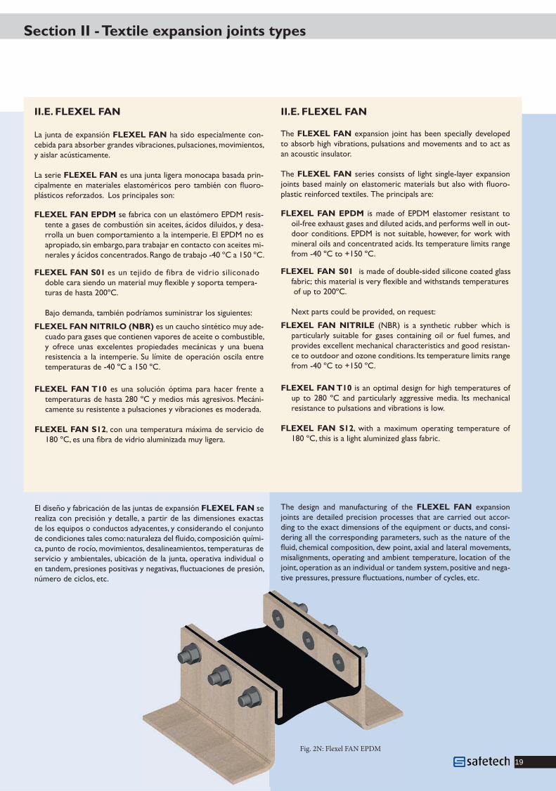
II.E. FLEXEL FAN
The FLEXEL FAN expansion joint has been specially developed to absorb high vibrations, pulsations and movements and to act as an acoustic insulator.
The FLEXEL FAN series consists of light single-layer expansion joints based mainly on elastomeric materials but also with fl uoro-plastic reinforced textiles. The principals are:
FLEXEL FAN EPDM is made of EPDM elastomer resistant to oil-free exhaust gases and diluted acids, and performs well in out-door conditions. EPDM is not suitable, however, for work with mineral oils and concentrated acids. Its temperature limits range from -40 ºC to +150 ºC.
FLEXEL FAN NITRILE (NBR) is a synthetic rubber which is particularly suitable for gases containing oil or fuel fumes, and provides excellent mechanical characteristics and good resistan-ce to outdoor and ozone conditions. Its temperature limits range from -40 ºC to +150 ºC.
FLEXEL FAN T10 is an optimal design for high temperatures of up to 280 ºC and particularly aggressive media. Its mechanical resistance to pulsations and vibrations is low.
FLEXEL FAN S12 fo erutarepmet gnitarepo mumixam a htiw ,180 ºC, this is a light aluminized glass fabric.
The design and manufacturing of the FLEXEL FAN expansion joints are detailed precision processes that are carried out accor-ding to the exact dimensions of the equipment or ducts, and consi-dering all the corresponding parameters, such as the nature of the fl uid, chemical composition, dew point, axial and lateral movements, misalignments, operating and ambient temperature, location of the joint, operation as an individual or tandem system, positive and nega-tive pressures, pressure fl uctuations, number of cycles, etc.
II.E. FLEXEL FAN
La junta de expansión FLEXEL FAN ha sido especialmente con- ,sotneimivom ,senoicaslup ,senoicarbiv sednarg rebrosba arap adibec
y aislar acústicamente.
La serie FLEXEL FAN es una junta ligera monocapa basada prin-cipalmente en materiales elastoméricos pero también con fl uoro-plásticos reforzados. Los principales son:
FLEXEL FAN EPDM se fabrica con un elastómero EPDM resis-tente a gases de combustión sin aceites, ácidos diluidos, y desa-rrolla un buen comportamiento a la intemperie. El EPDM no es apropiado, sin embargo, para trabajar en contacto con aceites mi-nerales y ácidos concentrados. Rango de trabajo -40 ºC a 150 ºC.
FLEXEL FAN NITRILO (NBR) es un caucho sintético muy ade-cuado para gases que contienen vapores de aceite o combustible, y ofrece unas excelentes propiedades mecánicas y una buena resistencia a la intemperie. Su límite de operación oscila entre temperaturas de -40 ºC a 150 ºC.
FLEXEL FAN T10 es una solución óptima para hacer frente a temperaturas de hasta 280 ºC y medios más agresivos. Mecáni-camente su resistente a pulsaciones y vibraciones es moderada.
FLEXEL FAN S12, con una temperatura máxima de servicio de 180 ºC, es una fi bra de vidrio aluminizada muy ligera.
El diseño y fabricación de las juntas de expansión FLEXEL FAN se realiza con precisión y detalle, a partir de las dimensiones exactas de los equipos o conductos adyacentes, y considerando el conjunto de condiciones tales como: naturaleza del fl uido, composición quími-ca, punto de rocío, movimientos, desalineamientos, temperaturas de servicio y ambientales, ubicación de la junta, operativa individual o en tandem, presiones positivas y negativas, fl uctuaciones de presión, número de ciclos, etc.
Fig. 2N: Flexel FAN EPDM
Textil_exacto_impreso.indd 19 18/12/2014 18:48:53
FLEXEL FAN S01 is made of double-sided silicone coated glassfabric; this material is very flexible and withstands temperatures of up to 200ºC.
Next parts could be provided, on request:
FLEXEL FAN S01 es un tejido de fibra de vidrio siliconadodoble cara siendo un material muy flexible y soporta tempera-turas de hasta 200ºC.
Bajo demanda, también podríamos suministrar los siguientes:

a 20
Sección III - Confi guración. Accesorios
Fig. 3A: Muestras de diferentes marcos y de� ectores
Fig. 3A: Samples of di� erent types of frames and liners
Textil_exacto_impreso.indd 20 18/12/2014 18:48:54

21
Section III - Confi guration. Accessories
III.A. MARCOS. CONFIGURACIONES TÍPICAS
El marco metálico es la estructura necesaria para conec-tar el elemento fl exible de la junta de expansión a ambos conductos.
El marco puede ser parte de la junta de expansión, atorni-llado a la estructura del conducto, o implementado como parte integral del conducto (soldado).
Existen una gran variedad de geometrías para adecuarse a cada caso particular; atornilladas o soldadas, planas o verticales, con o sin defl ector.
Dimensionalmente hay dos parámetros de especial im-portancia en el rendimiento de la junta de expansión; una de ellas es la distancia entre marcos metálicos (longitud activa) y la otra es la altura a la que se sitúa el elemento fl exible.
La longitud activa proporciona fl exibilidad y debe ser cal-culada como un equilibrio entre los movimientos reque-ridos y la integridad dimensional de la junta de expansión.
La altura permite los desplazamientos laterales del com-pensador. Puesto que esta altura aleja el elemento fl exible de la corriente de gas rebaja la temperatura que le alcanza y reduce también la abrasión.
III.A. FRAMES. TYPICAL CONFIGURATIONS
The metal frame is the structure required to connect the fl exible element of the expansion joint to the duc-twork.
It may be implemented as part of the expansion joint, bolted to the mating ductwork structure, or as an inte-gral part of the duct (welded).
There is a wide variety of frame geometries to meet every particular application; bolted or welded connec- tion, fl at or vertical fl anges, with or without baffl es.
Dimensionally there are two main parameters that have an important impact on expansion joint performance; the distance between metal frames (expansion joint ac-tive length) and the height (fl exible element stand-off height).
The active length provides fl exibility and must be cal-culated as an optimum balance of movement require-ments and dimensional integrity.
The stand-off height, or setback, allows for lateral mo- vements. Since this is the distance between the fl exible element and the gas stream, it also allows for tempera-ture reduction and diminishes abrasion effects.
III.B. LINERS, BAFFLES
The metal liners or baffl es are protective elements de-signed to shield the expansion joint soft members from abrasion by solid particles suspended in the gas stream. They play a secondary role as heat defl ectors.
The liners dampen pressure fl uctuations resulting from turbulent fl ows, thereby reducing the harmful effect of fl utter on the fl exible element.
The metal liner reduces the entry of solid particles in the cavity, and also prevents them from escaping. There-fore the metal liners must be carefully designed when high particle contents are involved.
See fi gure 3A for some examples.
Fig. 3B: Sample metal frame with � at � anges, and no liners, welded to ductwork.
Fig. 3B: Ejemplo de marco metálico de bridas
planas, sin de� ector, soldado al conducto.
III.B. DEFLECTORES
El defl ector interno es un escudo metálico concebido para proteger las partes blandas de la junta de expansión de los efectos abrasivos de partículas sólidas en suspen-sión. Además actúan como defl ectores de calor.
Los defl ectores amortiguan las fl uctuaciones de los fl ujos turbulentos reduciendo así el efecto pernicioso que tie-nen sobre el elemento fl exible.
El defl ector metálico reduce la entrada de partículas só-lidas en la cavidad de la junta pero previenen también su salida. Por ello el diseño de los defl ectores debe ser cuida-doso en caso de alto contenido de partículas.
La fi gura 3A muestra algunos ejemplos.
Textil_exacto_impreso.indd 21 18/12/2014 18:48:54

a 22
Sección III - Confi guración. Accesorios
III.C. BOLSAS DE AISLAMIENTO. BOLSTERS
Las bolsas de aislamiento o bolsters desempeñan una doble función; como barreras térmicas y como relleno. En aque-llas aplicaciones con temperaturas de operación muy elevadas la incorporación de un bolster rebaja las temperaturas alcanzadas en la superfi cie del elemento fl exible hasta niveles seguros.
Además el bolster actúa como relleno impidiendo la acumulación de partículas sólidas que pueden formar depósitos y restar fl exibilidad a la junta de expansión. También impide la entrada en la cavidad de partículas de fuel inquemadas que eventualmente puedan causar un incendio.
El bolster amortigua las oscilaciones en la presión del medio, en conductos con fl ujo turbulento, protegiendo así al elemento fl exible de estas dañinas fl uctuaciones.
III.C. INSULATION BAGS. BOLSTERS
Insulation bags or bolsters play a dual role; as thermal barriers and as cavity fi llers. In applications with very high ope- rating temperatures, the use of a bolster lowers the temperatures reached on the surface of the fl exible member to safe levels.
The bolster also acts as a cavity fi ller, preventing the accumulation of solid particles that may build up deposits and reduce the fl exibility of the expansion joint. It also prevents the entry of unburned fuel particles that may eventually cause a fi re.
The bolster dampens the pressure oscillations of the medium in ducts with turbulent fl ow, thus protecting the fl exible element against these harmful fl uctuations.
Fig. 3C:Ejemplo de bolster en una junta Flexel GT 550 SP con de� ector cruzado. Sample of bolster in a Flexel GT 550 SP with double liner.
Fig. 3D: Los gases calientes transmi-ten calor a la estructura metálica del conducto. El bolster reduce la tempe-ratura que llegará al elemento � exible. Un marco con su� ciente altura unido a un adecuado acabado del aislamien-to externo del conducto permiten re-frigerar la brida.
Hot gases transfer heat to the metal structure of the duct. � e bolster re-duces the temperature upstream of the � exible member. A frame with the ri-ght height and a suitable arrangement of duct’s external insulation allows for � ange cooling.
Textil_exacto_impreso.indd 22 18/12/2014 18:48:54

23
Section III - Confi guration. Accessories
III.D. DRENAJES
Los conductos de gases que operan a temperaturas bajas, próximas al punto de rocío, y que generan condensados podrán necesitar vías para su evacuación. En efecto, en la cavidad de la junta de expansión se acumularán condesados que es necesario evacuar para evitar el ataque ácido y el peso adicional que suponen sobre los materiales de la junta de expansión. Para ello se utilizan puertos de drenaje implementados directamente sobre el elemento fl exible del compensador y que conectados a una tubería evacuarán los condesados. Materiales como PTFE virgen, FRP (Fiber-glass-Reinforced Plastic) o acero inoxidable son comúnmente utilizados.
III.E. KITS DE CIERRE Y REPARACIÓN
Safetech dispone de kits de cierre y reparación para realizar tanto montajes nuevos como reparaciones de todos los tipos de materiales empleados en nuestras juntas. Los kits de cierre se incluyen en todos los suministros que así lo necesiten.
Las juntas de expansión de PTFE necesitan de una máquina de soldar fl uoroplásticos que Safetech también ofrece a sus clientes.
III.D. DRAINS
Flues operating at low temperatures, close to the dew point, and generating condensates may need routes for their evacuation. Indeed, in the cavity of the expansion joint it is necessary to remove condensates in order to prevent acid attack and the extra weight on the expansion joint materials. Drainage ports are implemented directly on the fl exible element of the compensator with a pipe connected for condensate evacuation. Materials such as virgin PTFE, FRP (Fiberglass-Reinforced Plastic) and stainless steel are commonly used.
III.E. REPARATION AND SPLICING KITS
Safetech offers splicing and repair kits for both new assemblies and repairs of all types of materials used in our expansion joints. The splicing kits are included, where needed, with all our deliveries.
The PTFE expansion joints require a special heat sealing machine for fl uoroplastic materials that Safetech also offers to its customers.
Fig. 3E: Drenaje de PTFE / PTFE drain
Fig. 3F: Manguera de inoxidable conectada a drenajes de PTFE Stainless steel hose connected to PTFE drain ports
Fig. 3G: Control maquina de soldar PTFE Heat sealer control
Textil_exacto_impreso.indd 23 18/12/2014 18:48:54

a 24
Sección IV - Instalación
ALMACENAJE
Al recibir la mercancía se debe verifi car que ésta llega en perfectas condiciones; a continuación controlar que los items que fi guran en el albarán coinciden con su pedido, después, cerrar la caja y almacenar a cubierto (Fig. 1).
ANTES DE LA INSTALACIÓN
Antes de la instalación, debe verifi carse que las partes metálicas que soportan el compen-sador están de acuerdo con el diseño y plano elaborado a tal efecto, que están libres de proyecciones de soldadura, resaltes o elementos punzantes y, que las zonas de contacto con los tejidos tienen las aristas redondeadas (Fig. 2).
Si el espacio entre sectores de contrabrida es mayor de 2 mm, intercalar en la parte inferior, una chapa de 1 mm de espesor y un ancho equivalente al de la contrabrida (Fig. 3).
Para juntas de expansión con bridas verticales, el taladro en la contrabrida será avellanado de forma que la cabeza del tornillo, cuando se produce el movimiento axial, no dañe la capa de cobertura del compensador (Fig. 4).
Una vez revisados todos estos puntos, se desembalarán las juntas, preferentemente en el lugar en que se vaya a realizar el montaje, si alguna quedase sin instalar, permanecerá en la caja, la cual, quedará cerrada (Fig. 5). En caso de una unidad completa, los dispositivos de arriostrado y transporte no deben retirarse hasta la fi nalización del montaje, asegurándose que son retirados antes de la puesta en marcha (Fig. 6 & 7).
INSTALACIÓN
Con el fi n de asegurar una correcta instalación, se deberán tener en cuenta los siguientes puntos:
Un andamio en todo el perímetro de la junta facilitará la instalación.
En caso de juntas de expansión grandes y pesadas, las cuales no pueden ser trasladadas en su caja al lugar de montaje, se prepara una plataforma para izarlas, en ningún caso directamente (Fig. 8).
Durante el montaje, deben ser protegidas de proyecciones de soldadura, elementos punzantes, apoyo de anda-mios e incluso de caminar sobre ellas.
Una vez situada y alineada la junta en su emplazamiento, ésta podrá sujetarse con mordazas, si la junta viene taladrada, la contrabrida y los tornillos se montarán de inmediato, sin apretarlas hasta que toda la junta esté instalada.
Una vez terminada esta fase, se apretarán todos los tornillos con una llave dinamométrica al par correspondiente, según el tipo de compen-sador. En ningún caso se debe retaladrar una junta ya taladrada, esto implicaría la pérdida de garantía.
En caso de que las juntas vengan sin taladrar, el compensador se situará sobre la brida del conducto, posicionando y alineando correcta-mente la contrabrida, asegurándola con mordazas apretadas fuertemente, (Fig. 9), para proceder al taladrado (Fig. 10) del compensador para posteriormente introducir el tornillo con su tuerca y arandela, nunca deben realizarse más de dos taladros (una a cada lado de la mordaza); al igual que en el caso anterior, el apriete defi nitivo se hará al fi nal del montaje de todo el compensador, aplicando el par correspondiente.
Si la instalación es de una unidad completa, antes de su izado se debe verifi car que el hueco existente entre conductos se corresponde con la junta, de no ser así, los dispositivos de arriostrado deben ser corregidos. En ningún caso se usarán dispositivos de izado que dañen la junta.
En caso de que la junta de expansión vaya acompañada de una bolsa de aislamiento, el procedimiento de insta-lación dependenderá de este elemento:
• Si es con bridas, se instalará al mismo tiempo que la junta de expansión, siguiendo las instrucciones dadas anteriormente (Fig. 13).
• Si es sin bridas, está será colocada en el hueco existente en las partes metálicas, para posteriormente colocar el compensador.
• Si es aislamiento suelto, éste se retacará en la cavidad, para posteriormente colocar el compensador.• Tanto la bolsa de aislamiento como el aislamiento deben llenar completamente el hueco existente en la
parte metálica.
DESPUES DE LA INSTALACIÓN
Una vez terminada la instalación, la junta debe protegerse de posibles accidentes hasta la puesta en marcha; cuando ésta se produce se verifi -cará que la junta esté limpia, en perfecto estado y libre de pinchazos que puedan provocar el deterioro acelerado de la misma. A continuación, y teniendo en cuenta las diferencias de compresibilidad de los materiales, acero y textil, se procederá a reapretar los tornillos, no más tarde de una semana tras la puesta en marcha.
Los remates del calorifugado son muy importantes para la vida de los compensadores y deben realizarse cuidadosamente.
Si la temperatura de los gases está por encima de los 350 ºC, el compensador necesita mayor disipación de calor, por tanto, se usará el remate tipo “A”. Si la temperatura es inferior a 350 ºC, se usará el remate tipo “B”.
Las juntas de expansión textiles no deben ser calorifugadas, a excepción de aquellas en las que la temperatura del fl uido no supera los 230 ºC y el compensador es un FLEXEL RA.
INSPECCIÓN Y MANTENIMIENTO
Las juntas de expansión textiles no necesitan un mantenimiento especial, simplemente se debe controlar si aparecen signos de descomposición en la cara exterior. Dependiendo del tipo, éstas comienzan por decolorarse y escamarse, bien sea el ataque por causas térmicas o químicas; si aparecen estos síntomas, debe ponerse en contacto con Safetech para programar el suministro y montaje de la junta, evitando situaciones de entregas apresuradas con incremento de costes.
Textil_exacto_impreso.indd 24 18/12/2014 18:48:55

25
Section IV - Installation
STORAGE
On reception of the materials, verify that boxes or crates arrive in perfect conditions. Then, check that the items on the packing list match the purchase order. After correct verifi cation, close the package and store in a waterproof location (Fig. 1).
BEFORE INSTALLATION
Before installation, verify that the steel parts supporting the expansion joint are in ac-cordance with the design drawings, that they are free from welding projections, edges or cutting elements, and that the areas in contact with the materials have the edges rounded off (Fig. 2).
If the space between back fl anges is higher than 2 mm, a 1 mm-thick plate, with the same width as the back fl ange, must be located in the bottom (Fig. 3).
For expansion joints with vertical fl anges, holes in the back fl ange must be countersunk, such that the head of the bolt does not damage the expansion joint cover when axial mo-vement occurs (Fig. 4).
Once all the above points have been verifi ed, the expansion joints may be unpacked, pre- ferably at the same location where the installation will take place. If any of the expansion joints remain uninstalled, they shall be kept in the package, which shall be closed (Fig. 5). In the case of complete units, the bracing and transport devices must not be removed until the end of the assembly, but there must be assurance that they are all removed before initial start-up of the system. (Figs. 6 & 7).
INSTALLATION
In order to assure a correct installation, the following points must be observed:
A scaffolding around the entire perimeter of the expansion joint will facilitate the installation.
In the case of large or heavy expansion joints that cannot be moved inside their packing up to their fi nal location, a platform shall be used to lift them. Never lift expansion joints directly (Fig. 8).
During the installation, the expansion joints must be protected from welding projections, cutting elements and scaffolding supports. Never walk on the expansion joints.
Once the expansion joint has been placed and aligned in its fi nal position, fi x it with clamps. Or, if the joint is delivered pre-drilled, mount the back fl ange and insert the bolts without tightening until the expansion joint is completely installed.
When this phase is fi nished, all bolts will be tightened with the corresponding torque key. In no case a drilled expansion joint shall be drilled again, as this will result in the loss of the guarantee.
If the expansion joint is delivered with no holes, it will be positioned over the duct fl ange, aligning it correctly against the back fl ange and assuring it with strongly tightened clamps, (Fig. 9), in order to proceed with the drilling of the expansion joint (Fig. 10). Subsequently, the bolt, nut and washer shall be installed. Never drill more than two holes, one on either side of the clamp. As in the previous case, the defi nitive torque will be applied at the end of expansion joint assembly (Fig. 11).
If a complete unit, with steel frames assembled, is to be installed, check the space available between ducts before lifting the expansion joint. If the spaces do not match, the lifting devices must be corrected. Never use lifting devices that might damage the expansion joint (Fig. 12).
If the expansion joint includes an insulation bag /bolster, the installation procedure may vary depending on that element:
• If it is a fl anged bolster, it will be installed at the same time as the expansion joint, following the above instructions (Fig. 13).• If the bolster has no fl anges, it will be located in the space existing between the steel parts and later the expansion joint will be assembled.• If it is loose fi ll insulation, this will be fi tted and compacted in the space and then the expansion joint will be installed.• Both the bolster and the insulation layer must completely fi ll the space existing in the steel part.
AFTER INSTALLATION
On completion of the installation, the expansion joint shall be protected against any possible accidents until the start-up of the system. At this moment the expansion joint must be verifi ed to be clean, in perfect condition and free from any cut that may cause failure. Then, and considering the different compressibility of steel and fabric materials, the bolts shall be retightened no later than one week following start-up.
The lagging is very important for the life of the expansion joint and shall be carried out carefully.
If the temperature of the gases is higher than 350 ºC, the expansion joint will need a higher protection against heat, and therefore Type A lagging will be used. If the temperature is lower than 350 ºC, Type B lagging will be used.
The fabric expansion joints shall not be lagged, except where the fl uid temperature does not reach 230 ºC and the expansion joint is a FLEXEL RA type.
INSPECTION AND MAINTENANCE
Fabric expansion joints do not need any special maintenance, other than simple verifi cation of the external layer to check for decomposition. Depending on the type of expansion joint, the external layer may start losing its original colour or develop scales due either to thermal attack or chemical attack. If these symptoms appear, it will be necessary to contact Safetech in order to schedule the supply and installation of the expansion joint, avoiding urgent delivery situations with the corresponding increase in cost.
Textil_exacto_impreso.indd 25 18/12/2014 18:48:55

a 26
Flexel
Marco metálico, Contrabridas, Bolster
CM
n n n
Nom
bre
de p
rodu
cto
Prod
uct n
ame
Nom
bre
com
erci
alTr
ade
nam
e
Mod
elo
Mod
el
Sub-tipo / Sub-type
sub-type / accessories
TemperaturaTemperature
Nombre de producto de nuestras juntas de expansión metálicasProduct name of our metalexpansion joints
Sub-tipo ‘S’ para calidad premiumSub-type ‘S’ for premium quality
RA
GTFAN
ENERGY
CGNombre de producto de nuestras juntas de expansión de cauchoProduct name of our rubberexpansion joints
Sección V - Apéndice A. Datos útiles / Useful data
EQUIVALENCIA DE DEPRESIONES / NEGATIVE PRESSURE CONVERSIONS1 torr = 1 mm dew Hg = 1,333 milibar = 0,0136 m de agua
vacío absoluto = depresión o torr = depresión de 760 torrs = depresión de 100%
EQUIVALENCIA DE PRESIONES / PRESSURE CONVERSIONS
1 bar = 1,02 kg/cm2 = 105 pascals = 0,987 atm = 750 mm de Hg = 10,2 m de agua
LONGITUD / LENGTH SUPERFICIE / SURFACE VOLUMEN / VOLUME
centímetro / inch
metro / foot
1 cm = 0,3937 in
1 in = 2,54 cm
1 ft = 0,305 m
centímetro2 / square inch
metro2 / square foot
1 cm2 = 0,155 sq. in
1 sq. in = 6,452 cm2
1 m2 = 10,764 sq. ft
1 sq. ft = 0,093 m2
metro cúbico / cubic foot1 m3 = 35,315 cu. ft1 cu. ft = 0,0283 m3
CAPACIDAD / CAPACITY
litro / US gallon1 l = 0,264 gal.1 gal. = 3,785 l
MASA / MASS VELOCIDADES / SPEED CAUDAL / FLOW
kilogramo / pound1 kg = 2,2046 lb1 lb = 0,4536 kg
metro por segundo / foot per minute1 m/s = 196,85 fpm1 fpm = 0,0051 m/s
metro cúbico por hora / cubic foot per hour1 m3/h = 0,589 cfm1 cfm = 1,699 m3/h
PRESIÓN / PRESSURE DEPRESIÓN / NEGATIVE PRESSURE TEMPERATURA / TEMPERATURE
kg por centímetro cuadrado / pound per square inch1 kg/cm2 = 14,22 psi1 psi = 0,07 kg/cm2
milímetro de mercurio / inch of Hg1 mm Hg = 0,039 in Hg
grado Celsius / Farenheit degreeºF = 9/5 C + 32C = 5/9 ( F - 32)º
ºº
CONVERSION DE UNIDADES / UNIT CONVERSION
EQUIVALENCIA DE TEMPERATURAS / TEMPERATURE CONVERSIONSºC -20 -10 0 10 20 30 40 50 60 70 80 90 100 110 120 130 140ºF -4 14 32 50 68 86 104 122 140 158 176 194 212 230 248 266 284
CODIFICACIÓN DE PRODUCTOS / PRODUCT CODING
Textil_exacto_impreso.indd 26 18/12/2014 18:48:55

27
Juntas en ventilador de tiro inducidoJoints in an induced dra� fan
Junta de expansión en entrada compuerta de guillotina.Expansion joint at inlet of a guillotine damper.
Junta de expansión a la salida de un ventilador de tiro forzado.
Expansion joint at the outlet of a forced dra� fan.
Textil_exacto_impreso.indd 27 18/12/2014 18:48:59

Polígono Guardi 4 Sector 13-1 Pabellones 84-8920213 IdiazabalApdo. 107 20700 Zumárraga Guipuzkoa, SPAINTel.: +34 943 800 129Fax: +34 943 800 140
www. grupooria.com
Textil_exacto_impreso.indd 28 18/12/2014 18:48:59
Rev. Jan15