Embed Size (px)
Citation preview

KA / KM / KRKM10, KM26, KM26z, KM29, KM38, KM40, KM46, KM90, KM115
KR80, KR140KA105
Last update: 02.01.07
ME-Meßsysteme GmbH Neuendorftstr. 18a Tel.: +49 3302 559 282D-16761Hennigsdorf Fax: +49 3302 559 141

Table of contentsForce Sensor KM10...............................................................................................................4
Dimensions........................................................................................................................4Technical Data...................................................................................................................5Pin Configuration...............................................................................................................5
Force Sensor KM26...............................................................................................................6Dimensions........................................................................................................................6Technical Data...................................................................................................................7Pin Configuration...............................................................................................................7
Force Sensor KM26z.............................................................................................................8Dimensions........................................................................................................................8Technical Data...................................................................................................................9Pin Configuration...............................................................................................................9
Force Sensor KM29.............................................................................................................10Dimensions......................................................................................................................10Technical Data.................................................................................................................11Pin Configuration.............................................................................................................11
Force Sensor KM38.............................................................................................................12Dimensions......................................................................................................................12Description.......................................................................................................................12Force Sensor KM38.........................................................................................................13Technical Data.................................................................................................................13Pin Configuration.............................................................................................................13
Force Sensor KM40.............................................................................................................14Dimensions......................................................................................................................14Technical Data.................................................................................................................15Pin configuration..............................................................................................................15
Force Sensor KM46.............................................................................................................16Dimensions......................................................................................................................16Technical Data.................................................................................................................17Pin Configuration.............................................................................................................17
Force Sensor KM90.............................................................................................................18Dimensions......................................................................................................................18Technical Data.................................................................................................................19Pin Configuration.............................................................................................................19
Force Sensor KM115...........................................................................................................20Dimensions......................................................................................................................20Technical Data.................................................................................................................21Pin Configuration.............................................................................................................21
Load Cell KR80....................................................................................................................22Dimensions......................................................................................................................22Technical Data.................................................................................................................23Pin Configuration.............................................................................................................23
Load Cell KR140..................................................................................................................24Dimensions......................................................................................................................24Technical Data.................................................................................................................25Pin Configuration.............................................................................................................25
2 User's Manual

Load Cell KA105..................................................................................................................26Dimensions......................................................................................................................27Technical Data.................................................................................................................28Pin Configuration.............................................................................................................28
User's Manual 3

Force Sensor KM10Nominal force ranges 25N, 100N, 500N
The KM 10 is a membrane force sensor in ultra miniature design.
Dimensions
4 User's Manual

Force Sensor KM10Nominal force ranges 25N, 100N, 500N
Technical Data
Force sensor compressionConstruction membraneDiameter × height 9,8 x 4 mm × mmForce transmission spherical cap ∅2.4, radius 4 mmFastening mmMaterial stainless steelAccuracy class 1
Nominal force FN 25, 100, 500 NOperating force 150 %FNBreaking force 300 %FNLimiting lateral force 20 %FN
Nominal temperature range -20…+60 °COperating temperature range -20…+70 °CStorage temperature range -20…+70 °C
Nominal output (SN) 1 ±0.5 1) mV/VZero signal tolerance ±5 %FNMax. supply voltage 10 VInput resistance 350 ±2.5 OhmOutput resistance 350 ±2.5 OhmInsulation resistance > 5 ⋅ 109 OhmConnection, 4-conductor open 3.0 m
Linearity error ≤ 1 % SN Reversal error ≤ 0.5 % SN Temperature coeff. of the zero signal
≤ ±0.05 %FN /K
Temperature coeff. of the nominal output
≤ ±0.05 % SN /K
Creep error (30 min) ≤ 0.5 % SN
1) the nominal output is given in the printout;
Pin Configuration+US positive bridge supply red-US negative bridge supply black shield: transparent+UD positive bridge output green-UD negative bridge output white
User's Manual 5

Force Sensor KM26Nominal force ranges 0.5kN, 1kN, 2kN, 5kN, 10kN
The force sensor KM 26 is a membrane-type force sensor with small dimensions.It is suitable for measuring compressive forces. The force sensor is fitted into a flat recess and if required, fixed in place with adhesive. There is a spherical cap of radius 40 mm provided for the force transmission.The method of protection is IP 67.As against force sensors of the KD (double-beam) series, lateral forces result in a measurement error.Therefore, the force transmission must be centric and free of lateral forces.
Dimensions
6 User's Manual
Ø25,4
Ø8 R40
2
11
±0,3

Force Sensor KM26Nominal force range 0.5kN, 1kN, 2kN, 5kN, 10kN
Technical Data
Force sensor compressionConstruction membraneDiameter × height 26 x 11 mm × mmForce transmission spherical cap ∅8, radius 40 mmFastening mmMaterial stainless steelAccuracy class 1
Nominal force FN 0.5, 1, 2, 5, 10 kNOperating force 150 %FNBreaking force 300 %FNLimiting lateral force 20 %FN
Nominal temperature range -20…+60 °COperating temperature range -20…+70 °CStorage temperature range -20…+70 °C
Nominal output (SN) 1.0 ±0.2 mV/VZero signal tolerance ±5 %FNMax. supply voltage 10 VInput resistance 380 ±30 OhmOutput resistance 350 ±2.5 OhmInsulation resistance > 5 ⋅ 109 OhmConnection, 4-conductor open 3.0 m
Linearity error ≤ 0.2 % SN Reversal error ≤ 0.2 % SN Temperature coeff. of the zero signal
≤ ±0.05 %FN /K
Temperature coeff. of the nominal output
≤ ±0.05 % SN /K
Creep error (30 min) ≤ 0.5 % SN
Pin Configuration+US positive bridge supply red-US negative bridge supply black shield: transparent+UD positive bridge output green-UD negative bridge output white
User's Manual 7
Force Sensor KM26zNominal force ranges 0.2kN, 0.5kN, 1.0kN, 2.0kN, 5.0kN
The force sensor KM26z is a membrane-type force sensor with small dimensions.It is suitable for measuring compressive and tensile forces. For force transmission there exist two threads M6.Environmental protection rating is IP 67.
Force transmission must be free of lateral forces.
Dimensions
8 User's Manual

Force Sensor KM26zNominal force range 0.2kN, 0.5kN, 1.0kN, 2.0kN, 5.0kN
Technical Data
Force sensor compressionConstruction membraneDiameter × Height 25.4 x 16 mm × mmForce transmission 2 x threads M6
Material special steel from 1kNaluminum up to 0.5kN
Accuracy classes 1
Nominal force FN 0.2, 0.5, 1.0, 2.0, 5.0 kNOperating force 150 %FNBreaking force 300 %FNLimiting lateral force 20 %FN
Nominal temperature range -20…+60 °COperating temperature range -20…+70 °CStorage temperature range -20…+70 °C
Nominal output (SN) 1.0 ±0.2 mV/VZero signal tolerance ±5 %FNMax. supply voltage 10 VInput resistance 700 ±30 OhmOutput resistance 700 ±2.5 OhmInsulation resistance > 5 ⋅ 109 OhmConnection, 4-conductor open 3 m
Linearity error ≤ 0.2 % SN Reversal error ≤ 0.2 % SN Temperature coeff. of the zero signal
≤ ±0.05 %FN /K
Temperature coeff. of the nominal output
≤ ±0.05 % SN /K
Creep error (30 min) ≤ 0.5 % SN
Pin Configuration+US positive bridge supply red-US negative bridge supply black shield: transparent+UD positive bridge output green-UD negative bridge output white
User's Manual 9

Compressive load: positive output signal
Force Sensor KM29Nominal force ranges ±100N, ±200N, ±500N, ±1000N
The force sensor KM 29 is a membrane force sensor with small dimensions. It is suitable for measuring tensile and compressive forces. It is fastened by means of three through-holes to an even surface. There is a thread M4 provided for the transmission of the force.Environmental protection rating is IP 67.In contrast to force sensors of the KD series (double beam), lateral forces result in a measurement error.Therefore, the force transmission has to be centric and preferably via a screwed-in spherical cap.
Dimensions
10 User's Manual

Force Sensor KM29Nominal force ranges ±100N, ±200N, ±500N, ±1000N
Technical Data
Force sensor tension / compressionConstruction membraneDiameter × Height 29 × 18 mm × mmForce transmission 1 × M4 mmFastening 3 × ∅3.2 mmMaterial aluminumAccuracy class 1
Nominal force FN 100, 200, 500, 1000 NOperating force 150 %FNBreaking force 300 %FNLimiting lateral force 20 %FN
Nominal temperature range -20…+60 °COperating temperature range -20…+70 °CStorage temperature range -20…+70 °C
Nominal output (SN) 1.0 ±0.2 mV/VZero signal tolerance ±5 %FNMax. supply voltage 10 VInput resistance 380 ±30 OhmOutput resistance 350 ±2.5 OhmInsulation resistance > 5 ⋅ 109 OhmConnection, 4 conductor open 1.5 m
Linearity error ≤ 0.2 %SNReversal error ≤ 0.2 %SNTemperature coeff. of the zero signal
≤ ±0.05 %FN /K
Temperature coeff. of the nominal output
≤ ±0.05 %SN /K
Creep error (30 min) ≤ 0.5 %SN
Pin Configuration+US positive bridge supply red brown-US negative bridge supply blue yellow shield: black+UD positive bridge output green green-UD negative bridge output yellow white
User's Manual 11

Force Sensor KM38Nominal force ranges 1kN, 2kN, 5kN, 10kN, 20kN
Dimensions
DescriptionThe minature force sensor KM38 is exceptionally suitable for measuring preload of bolts on account of its flat construction and its through hole. But the through hole 7mm is also suitable for introduction of a force transmission. With a spherical cap the force transmission can be centered and made free of lateral force .Through the introduction of half liners or prisms these force sensors can be adapted to the measurement of rolling forces.
The three M2.5 thread holes on the bottom side permit the attachment of the sensor or the fitting of a prism.
12 User's Manual
ø 38,1
ø 13,5
ø 7 H8
ø 33,53x M2,5x0,45
109
- 0,1+0,3

Force Sensor KM38Nominal force ranges 1kN, 2kN, 5kN, 10kN, 20kN
Technical Data
Force sensor compressionConstruction membraneDiameter × height 38.1 x 10 mm × mmForce transmission upon area ø13,5...ø7 mmFastening planar support ø38.1...ø29 mmMaterial stainless steelAccuracy class 1
Nominal force FN from 1...20 kNNominal displacement < 0.1 mmOperating force 150 %FNBreaking force > 300 %FNLimiting lateral force 10 %FN
Nominal temperature range +10…+60 °COperating temperature range -20…+80 °CStorage temperature range -40…+80 °C
Nominal output (SN) 1.0 ±0.1% mV/VZero signal tolerance ±10 %FNMax. supply voltage 10 VInput resistance 700 ±50 OhmOutput resistance 700 ±5 OhmInsulation resistance > 5 ⋅ 109 OhmConnection, 4 conductor open 3 m
Linearity error << 0.5 % SN Reversal error << 0.1 % SN Temp. coeff. of the zero signal ≤ ±0.02 % FN /KTemp. coeff. of the nominal output ≤ ±0.02 % SN /KZero point return error (30 min) << 0.1 % SN Creep error (30 min) << 0.1 % SN
Pin Configuration+US positive bridge supply red-US negative bridge supply black+UD positive bridge output green-UD negative bridge output white
User's Manual 13

Force Sensor KM40Nominal force ranges 0.5kN, 1kN, 2kN, 5kN, 10kN
The force sensor KM 40 is a precision force sensor in membrane construction for the measurement of compressive forces. The force sensor is fastened to a flat surface with four screws M4. There is a spherical cap with a radius of 50 mm provided for the force transmission.Environmental protection rating is IP 67.In contrast to the force sensors of the KD (double-beam) series, lateral forces result in a measurement error.Therefore, the force transmission must be centric.
Dimensions
14 User's Manual
Ø40
Ø11
ca. 12 M4
6
21
25Ø30
Ansicht von unten:
R50
View from below:

Force Sensor KM40Nominal force ranges 0.5kN, 1kN, 2kN, 5kN, 10kN
Technical Data
Force sensor compressionConstruction membraneDiameter × Height 40 × 25 mm × mmForce transmission spherical cap ∅11, radius 50 mmFastening 4 x M4 mmMaterial stainless steelAccuracy classes 0.5 or 0.2 %
Nominal force FN 0.5, 1, 2, 5, 10 kNOperating force 150 %FNBreaking force 300 %FNLimiting lateral force 20 %FN
Nominal temperature range -20…+60 °COperating temperature range -20…+70 °CStorage temperature range -20…+70 °C
Nominal output (SN) 1.0 ±0.2% mV/VZero signal tolerance ±5 %FNMax. supply voltage 10 VInput resistance 380 ±30 OhmOutput resistance 350 ±2.5 OhmInsulation resistance > 5 ⋅ 109 OhmConnection, 4-conductor open 1.5 m
Linearity error ≤ 0.2 % SN Reversal error ≤ 0.2 % SN Temperature coeff. of the zero signal
≤ ±0.05 %FN /K
Temperature coeff. of the nominal output
≤ ±0.02 % SN /K
Creep error (30 min) ≤ 0.1 % SN
Pin configuration+US positive bridge supply brown-US negative bridge supply yellow shield: black+UD positive bridge output green-UD negative bridge output white
User's Manual 15

Force Sensor KM46Nominal force range 50kN
The force sensor KM 46 is a force sensor in membrane construction for measurement of compressive forces. The force sensor is fastened to a flat surface with four screws M4. There is a spherical cap with a radius of 80 mm intended for force transmission.Environmental protection rating is IP 67.In contrast to the force sensors of the KD (double-beam) series, lateral forces result in a measurement error.Therefore, force transmission must be centric and free of lateral forces.
Dimensions
16 User's Manual
View from below:

Force Sensor KM46Nominal force range 50kN
Technical Data
Force sensor compressionConstruction membraneDiameter × Height 46 × 28 mm × mmForce transmission Spherical cap ∅16, radius 80 mmFastening 4 x M4 mmMaterial stainless steelAccuracy class 1
Nominal force FN 50 kNOperating force 150 %FNBreaking force 300 %FNLimiting lateral force 20 %FN
Nominal temperature range -20…+60 °COperating temperature range -20…+70 °CStorage temperature range -20…+70 °C
Nominal output (SN) 1.0 ±0.2 mV/VZero signal tolerance ±5 %FNMax. supply voltage 10 VInput resistance 380 ±30 OhmOutput resistance 350 ±2.5 OhmInsulation resistance > 5 ⋅ 109 OhmConnection, 4 conductor open 1.5 m
Linearity error ≤ 0.2 % SN Reversal error ≤ 0.2 % SN Temperature coeff. of the zero signal
≤ ±0.05 %FN /K
Temperature coeff. of the nominal output
≤ ±0.05 % SN /K
Creep error (30 min) ≤ 0.2 % SN
Pin Configuration+US positive bridge supply red brown-US negative bridge supply blue yellow shield: black+UD positive bridge output green green-UD negative bridge output yellow white
User's Manual 17

Force Sensor KM90Nominal force ranges 20 kN, 50 kN
The force sensor KM 90 is a membrane-type force sensor for measurement of compressive forces. The force sensor is fastened to an even surface with four screws M12. For force transmission there exists a spherical cap with radius 100 mm. Environmental protection is IP 67.
Dimensions
18 User's Manual

Force Sensor KM90Nominal force ranges 20 kN, 50 kN
Technical Data
Force sensor compressionConstruction membraneDiameter × height 90 × 48 mm × mmForce transmission spherical cap ∅24, radius 100 mmFastening 4 x M12 mmMaterial stainless steelAccuracy class 0.5 / 0.2
Nominal force FN 20, 50 kNOperating force 150 %FNBreaking force 500 %FNLimiting lateral force 20 %FN
Nominal temperature range -20…+60 °COperating temperature range -20…+70 °CStorage temperature range -20…+70 °C
Nominal output (SN) 1.0 ±0.005 mV/VZero signal tolerance ±5 %FNMax. supply voltage 10 VInput resistance 380 ±30 OhmOutput resistance 350 ±2.5 OhmInsulation resistance > 5 ⋅ 109 OhmConnection, 4-conductor open 1.5 m
Linearity error < 0.5 / < 0.2 % SN Reversal error << 0.5 / <<0.2 % SN Temperature coeff. of the zero signal
<< ±0.05 / << ±0.02 %FN /K
Temperature coeff. of the nominal output
<< ±0.05 / << ±0.02 % SN /K
Creep error (30 min) << 0,5 / << ±0.2 % SN
Pin Configuration+US positive bridge supply brown-US negative bridge supply yellow shield: black+UD positive bridge output green-UD negative bridge output white
User's Manual 19

Force Sensor KM115Nominal force range 100kN
The force sensor KM 115 is a membrane force sensor for measuring compressive forces. It is fastened to an even surface with four screws M12. A spherical cap with a radius of 160 mm is provided for the force transmission.Environmental protection is IP 67.
Dimensions
20 User's Manual
Shown displaced by 45

Force Sensor KM115Nominal force range 100kN
Technical Data
Force sensor compressionConstruction membraneDiameter × height 115 × 60 mm × mmForce transmission spherical cap ∅32, radius 160 mmFastening 4 x M12 mmMaterial stainless steelAccuracy classes 0.5 / 0.2 / 0.1
Nominal force FN 100 kNOperating force 150 %FNBreaking force 300 %FNLimiting lateral force 20 %FN
Nominal temperature range -20…+60 °COperating temperature range -20…+70 °CStorage temperature range -20…+70 °C
Nominal output (SN) 1.0 ±0.005 mV/VZero signal tolerance ±5 %FNMax. supply voltage 10 VInput resistance 380 ±30 OhmOutput resistance 350 ±2.5 OhmInsulation resistance > 5 ⋅ 109 OhmConnection, 4 conductor open 1.5 m
Linearity error << 0.2 % SN Reversal error << 0.2 % SN Temperature coeff. of the zero signal
<< ±0.02 %FN /K
Temperature coeff. of the nominal output
<< ±0.02 % SN /K
Creep error (30 min) << 0.2 % SN
Pin Configuration+US positive bridge supply brown-US negative bridge supply yellow shield: black+UD positive bridge output green-UD negative bridge output white
User's Manual 21
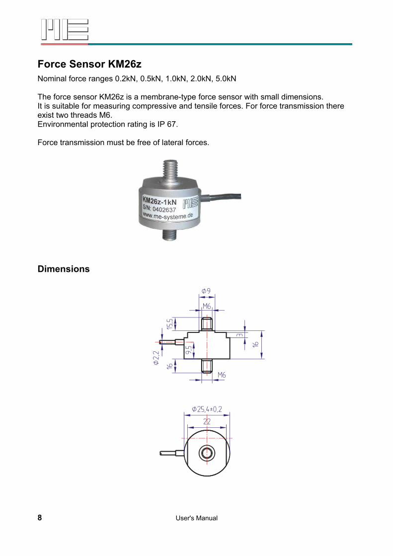
Load Cell KR80Nominal load ranges 0.25t, 0.5t, 1t, 2t, 3.5t, 5t, 10t
The load cell KR80 is a precision load cell in cylindrical design. It is hermetically sealed by welding and available in a calibratable design according to the European requirements OIML R-60 up to class C6. It stands out thanks to its particularly low measurement path of just 0.1mm.Environmental protection is IP 66.Force transmission is realized by a cylindrical load knob that has to be inserted into the hole ØD2. Optional pendular bases for applications in weighing technology can be installed.
Dimensions
0,25 t...1 t 2 t...5 t 10 tH 25 30 35D1 80 80 95D2 19 19 28.1D3 70 70 83D4 M10 15H7 24.9T1 15 20 14.8T2 9.5 8.5 10.0R 80 100 100
22 User's Manual

Load Cell KR80Nominal load ranges 0.25t, 0.5t, 1t, 2t, 3.5t, 5t, 10 t
Technical Data
Load cell compressionConstruction ring torsionMaterial stainless steel 1.4542Accuracy classes C1 (0.03%), C3 (0.02%), C6 (0.01%) Nominal loads (FN) 250kg...10,000kg
Accuracy class according to OIML R60 C1 C3 C6Maximum scale division value 1000 3000 6000Minimum scale division value FN /7000 FN /10000 FN /15000Combined error < ±0.03 < ±0.023 < ±0.0115 % SN Zero point return error (30 min) < ±0.05 < ±0.025 < ±0.0083 % SN Creep error (30 min) < ±0.05 < ±0.0245 < ±0.0123 % SN Temperature coeff. of the zero signal < ±0.014 < ±0.007 < ±0.0045 % FN /5°CTemperature coeff. of the rated output < ±0.025 < ±0.005 < ±0.0025 % SN /5°C
Operating load 150 % FN Breaking load 300 % FN Maximum lateral load 100 % FN
Displacement at FN 0.1 ±0.02 mm
Nominal temperature range -10...+40 °COperating temperature range -30...+70 °CStorage temperature range -50...+80 °C
Rated Output (SN) 2.0 ±0.1 (1.75 ±0.1 for 0.25t) mV/VZero Balance ±2 % FN Max. supply voltage 18 VInput resistance 1110 ±50 OhmOutput resistance 1025 ±25 OhmInsulation resistance > 5 ⋅ 109 OhmConnection, 4-conductor open 3 (5 from 2t) m
Pin Configuration+US positive bridge supply pink-US negative bridge supply gray shield: transparent+UD positive bridge output brown-UD negative bridge output white
User's Manual 23

Load Cell KR140Nominal load ranges 28t, 60t
The load cell KR140 is a precision load cell for high loads with extremely low installation height. It is hermetically sealed and available in a calibratable design according to the European requirements OIML R-60 up to class C3. Environemntal protection is IP 66.Load transmission is realized by a cylindrical load knob with radius 160mm that is laid upon the even surface Ø35,9 respectively Ø47,9 with help of a collar.
Dimensions
28 t 60 tØC 120 140B 46 62A 21 28
24 User's Manual
40Ø D
Ø C 7
AB
186,
5

Load Cell KR140Nominal load ranges 28t, 60t
Technical Data
Load cell compressionConstruction ring torsionMaterial stainless steel 1.4542Accuracy classes C2 (0.03%), C3 (0.02%),Nominal loads (FN) 28t, 60t
Accuracy class accord. to OIML R60 C2 C3Maximum scale division value 1000 3000Minimum scale division value FN /20000 FN /20000Combined error < ±0.03 < ±0.02 % SN Zero point return error (30 min) < ±0.03 < ±0.02 % SN Creep error (30 min) < ±0.005 < ±0.005 % SN Temperature coeff. of the zero signal < ±0.004 < ±0.004 % FN /5°CTemperature coeff. of the rated output
< ±0.006 < ±0.004 % SN /5°C
Operating load 150 % FN Breaking load 300 % FN Maximum lateral load 100 % FN
Displacement at FN 0.1 ±0.02 mm
Nominal temperature range -10...+40 °COperating temperature range -30...+70 °CStorage temperature range -50...+80 °C
Rated Output (SN) 2.0 ±0.1 mV/VZero Balance ±2 % FN Max. supply voltage 18 VInput resistance 1075 (28t) or 1350 (60t) ±100 OhmOutput resistance 930 (28t) or 1175 (60t) ±10 OhmInsulation resistance > 5 ⋅ 109 OhmConnection, 4-conductor open 10 m
Pin Configuration+US positive bridge supply pink-US negative bridge supply gray shield: transparent+UD positive bridge output brown-UD negative bridge output white
User's Manual 25

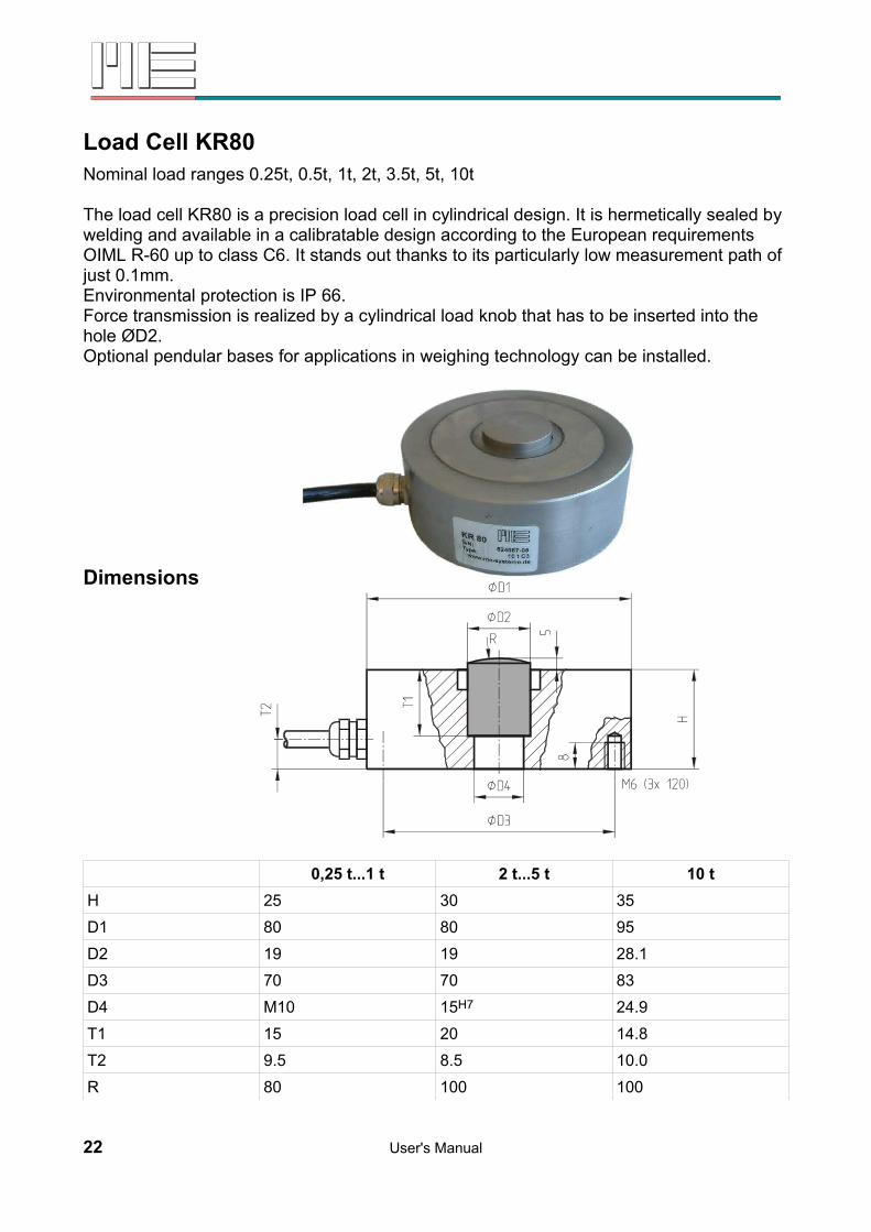
Load Cell KA105Nominal load ranges (compression) 10t, 25t, 40t, 60t, 100t
The compression load cell KA105 is a fully welded, hermetically sealed four pillar construction. It is thus mostly unsensitive to excentric load.Despite its high load capacity of up to 100t it is only 185mm high.Due to its geometry with a spherical cap and an even bottom surface the compression load cell can also be used for calibration of high load presses and for construction of automotive and rail-car scales.A central thread and a centering colllar on the bottom side of the sensor allows correct mounting of the sensor.
26 User's Manual
Dimensions
Nominal load 10t, 25t 40t, 60t 100tD1 73 105 152.4D2 31.8 58.7 79.2D3 58 82.5 123.8H 82.5 127 184.2R 152 152 432C 12 34 72.3E 6.5 8 23.6F 1.8 11 21.8G M12 x 1.75 M20 x 2.5 M20 x 2.5T 11 20 20
User's Manual 27
D1D2
EH
F
GD3
B
5025
R
40C
T

Load Cell KA105Nominal load ranges (compression) 10t, 25t, 40t, 60t, 100t
Technical Data
Load cell compressionConstruction multiple pillarsMaterial stainless steel 1.4542Accuracy classes CC (0.05%), C3 (0.02%) Nominal loads (FN) 10t...100t
Accuracy class accord. to OIML R60 CC C3Maximum scale division value 3000Minimum scale division value FN /7000 FN /12500Combined error < ±0.05 < ±0.02 % SN Zero point return error (30 min) < ±0.05 < ±0.0067 % SN Creep error (30 min) < ±0.06 < ±0.0245 % SN Temperature coeff. of the zero signal < ±0.025 < ±0.0056 % FN /5°CTemperature coeff. of the rated output < ±0.025 < ±0.0050 % SN /5°C
Operating load 150 % FN Breaking load 400 % FN Maximum lateral load 100 % FN
Nominal temperature range -10...+40 °COperating temperature range -40...+80 °CStorage temperature range -40...+90 °C
Rated Output (SN) 2.00 ±0.02 mV/VZero Balance ±2 % FN Max. supply voltage 18 VInput resistance 450 ±5 OhmOutput resistance 480 ±5 OhmInsulation resistance > 5 ⋅ 109 OhmConnection, 4-conductor open 20m
(10m at 10t)m
Pin Configuration+US positive bridge supply green-US negative bridge supply black shield: transparent/orange+UD positive bridge output white-UD negative bridge output red
28 User's Manual

Änderungen vorbehalten.Alle Angaben beschreiben unsere Produkte in allgemeiner Form.Sie stellen keine Eigenschaftszusicherung im Sinne des §459 Abs. 2, BGB, darund begründen keine Haftung.
Made in Germany Copyright 1999-2007ME-Meßsysteme GmbH
User's Manual 29

![TSUBAKI KABELSCHLEPP Parts listkabelschlepp.ru/fileadmin/img/carrier/PDFs/spare... · Item Materialtext [remarks] KR 052 KR 065 KR 095 KR 125 KR 150 KR 180 KR 200 KR 225 1](https://img.pdfslide.net/doc/110x75/5faa70404ba8b17fd45cfabf/tsubaki-kabelschlepp-parts-item-materialtext-remarks-kr-052-kr-065-kr-095-kr-125.jpg)