Embed Size (px)
Citation preview
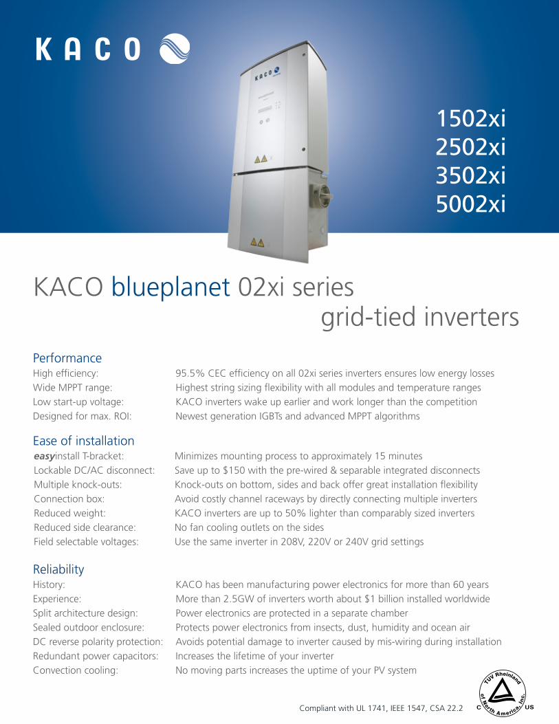
KACO blueplanet 02xi seriesgrid-tied inverters
1502xi 2502xi 3502xi 5002xi
PerformanceHigh efficiency: 95.5% CEC efficiency on all 02xi series inverters ensures low energy lossesWide MPPT range: Highest string sizing flexibility with all modules and temperature rangesLow start-up voltage: KACO inverters wake up earlier and work longer than the competitionDesigned for max. ROI: Newest generation IGBTs and advanced MPPT algorithms
Ease of installationeasyinstall T-bracket: Minimizes mounting process to approximately 15 minutesLockable DC/AC disconnect: Save up to $150 with the pre-wired & separable integrated disconnectsMultiple knock-outs: Knock-outs on bottom, sides and back offer great installation flexibilityConnection box: Avoid costly channel raceways by directly connecting multiple inverters Reduced weight: KACO inverters are up to 50% lighter than comparably sized invertersReduced side clearance: No fan cooling outlets on the sidesField selectable voltages: Use the same inverter in 208V, 220V or 240V grid settings
ReliabilityHistory: KACO has been manufacturing power electronics for more than 60 yearsExperience: More than 2.5GW of inverters worth about $1 billion installed worldwideSplit architecture design: Power electronics are protected in a separate chamberSealed outdoor enclosure: Protects power electronics from insects, dust, humidity and ocean airDC reverse polarity protection: Avoids potential damage to inverter caused by mis-wiring during installationRedundant power capacitors: Increases the lifetime of your inverterConvection cooling: No moving parts increases the uptime of your PV system
USCCompliant with UL 1741, IEEE 1547, CSA 22.2
Specifications are subject to change without notice. K
AC
O blueplanet 02xi series 10/01/10
Printed on post consumer material T: +1 (866) 522 6765 • F : +1 (415) 931 1688
[email protected] • www.kaco-newenergy.com
Model numberblueplanet
1502xiblueplanet
2502xi blueplanet
3502xiblueplanet
5002xiInput data (DC)
DC operating range (MPP) 125 – 400 VDC 200 – 450 VDC 200 – 510 VDC 200 – 510 VDC
Max. DC input voltage 550 VDC 550 VDC 600* VDC 600* VDC
Nominal DC input current 14.3 ADC 13.5 ADC 18.5 ADC 26.5 ADC
Max. DC input Isc current 21.45 ADC 21.45 ADC 28 ADC 40 ADC
Output data (AC)
Max. continuous output power (CEC) 1500 W 2500 W 3500 W 5000 W
Max. over-current protection 15 A 20 A 25 A 30 A
Max. continuous current240 V 8 AAC 12 AAC 16 AAC 24 AAC
208 V 8 AAC 12.5 AAC 17 AAC 24 AAC
AC operating range240 V 211 – 264 V 208 V 184 – 226 V220 V 198 – 242 V (for Mexico)
Frequency 60 Hz (59.3 – 60.5 Hz)
CEC rated efficiency240 V 95.5% 95.5% 95.5% 95.5%208 V 95% 95% 95.5% 95%
Additional data
AC/DC disconnect ratings AC: 300 V – 36 A / DC: 600 V – 40 A
Cooling True convection - ultimate reliability (5002xi - fan assisted)
DC reverse polarity protection Yes
Ground fault protection Integrated ground fault detector/interrupter (GFDI)
Grounding Field selectable positive or negative ground option
Visual displays Backlit LCD w/ convenient night switch & push button controls
Included accessory interfaces easyLink RS485 & S0 port
Ambient temp @ max AC power -4˚F – +104˚F (-20˚C – + 40˚C) -13˚F – +104˚F (-25˚C – + 40˚C)
Ambient operating temp -4˚F – +140˚F (-20˚C – + 60˚C) -13˚F – +140˚F (-25˚C – + 60˚C)
Thermal protection Yes
Noise emissions < 35 dB (silent operation) / 5002xi < 45 dB (near silent operation)
Night power consumption 0.3 W
Warranty Standard easySwap 10 years
Certifications
Safety compliance UL 1741, IEEE 1547, NEC, CSA 22.2 No.107.1-01
Communications compliance FCC Part 15 Class B
* - Unit will only feed power if the PV voltage is less than 550Vdc.
MonitoringKACO proLOG: Monitor up to 32 inverters as well as multiple sensors
KACO watchDOG: Integrated monitoring card decreases costs and increases reliability to give you the most innovative monitoring solution
easyLink data interface: Integrated RS485 comm card saves over $200 compared to some competitors
Integrated inverter display: Easy to use push-button interface to configure the inverter and access stored PV system data on the LCD screen
Integrated night switch: Activates inverter display even after the PV system has shut down
blueplanet web: Free monitoring option for residential systems up to 10 kW
WarrantyKACO easySwap policy: No hassle inverter exchange policy is linked to serial number not original owner. No paperwork necessary.
Reimbursement policy: KACO’s $150 warranty service reimbursement is among the best in the industry
KACO guarantee: 02xi series inverter repairs after warranty will never be more than $500
10 years standard warranty: Warranties are only as valuable as the strength and longevity of the manufacturer. KACO is one of the few established inverter companies older than the warranties they offer.
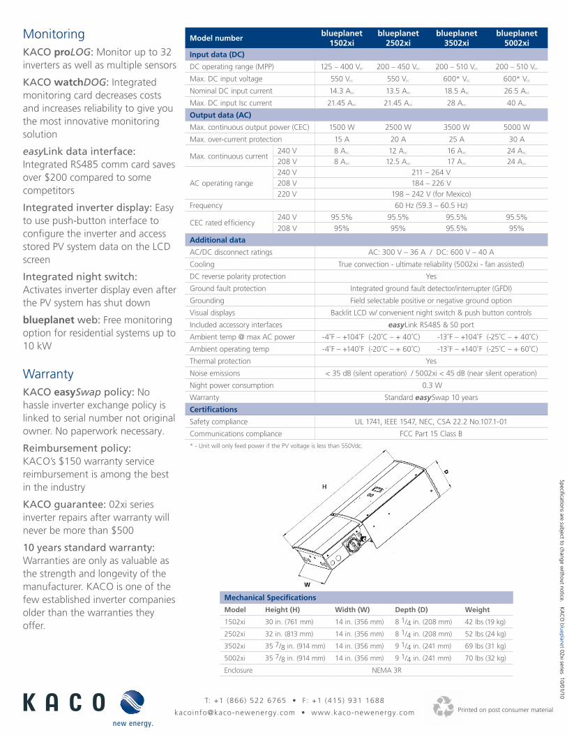
Mechanical Specifications
Model Height (H) Width (W) Depth (D) Weight
1502xi 30 in. (761 mm) 14 in. (356 mm) 8 1/4 in. (208 mm) 42 lbs (19 kg)
2502xi 32 in. (813 mm) 14 in. (356 mm) 8 1/4 in. (208 mm) 52 lbs (24 kg)
3502xi 35 7/8 in. (914 mm) 14 in. (356 mm) 9 1/4 in. (241 mm) 69 lbs (31 kg)
5002xi 35 7/8 in. (914 mm) 14 in. (356 mm) 9 1/4 in. (241 mm) 70 lbs (32 kg)
Enclosure NEMA 3R
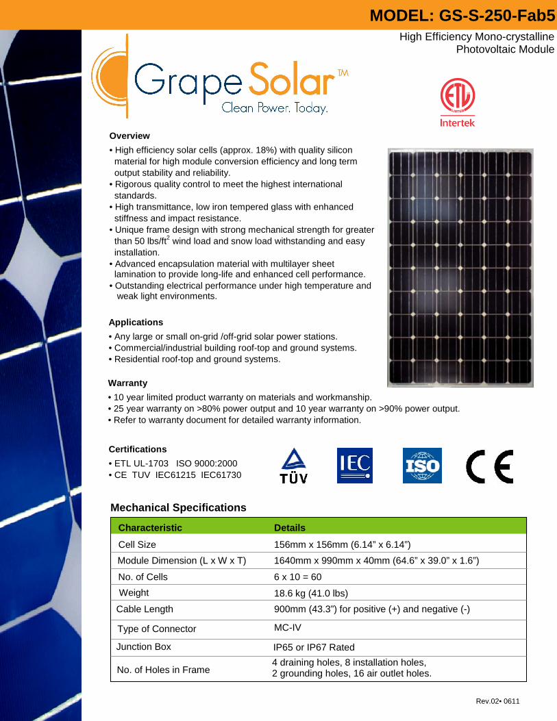
High Efficiency Mono-crystalline Photovoltaic Module
Overview
• High efficiency solar cells (approx. 18%) with quality silicon material for high module conversion efficiency and long term output stability and reliability. • Rigorous quality control to meet the highest international standards. • High transmittance, low iron tempered glass with enhanced stiffness and impact resistance. • Unique frame design with strong mechanical strength for greater than 50 lbs/ft2 wind load and snow load withstanding and easy installation. • Advanced encapsulation material with multilayer sheet lamination to provide long-life and enhanced cell performance. • Outstanding electrical performance under high temperature and weak light environments.
Warranty
• 10 year limited product warranty on materials and workmanship. • 25 year warranty on >80% power output and 10 year warranty on >90% power output. • Refer to warranty document for detailed warranty information.
Certifications
• ETL UL-1703 ISO 9000:2000 • CE TUV IEC61215 IEC61730
Characteristic Details
Cell Size 156mm x 156mm (6.14” x 6.14”)
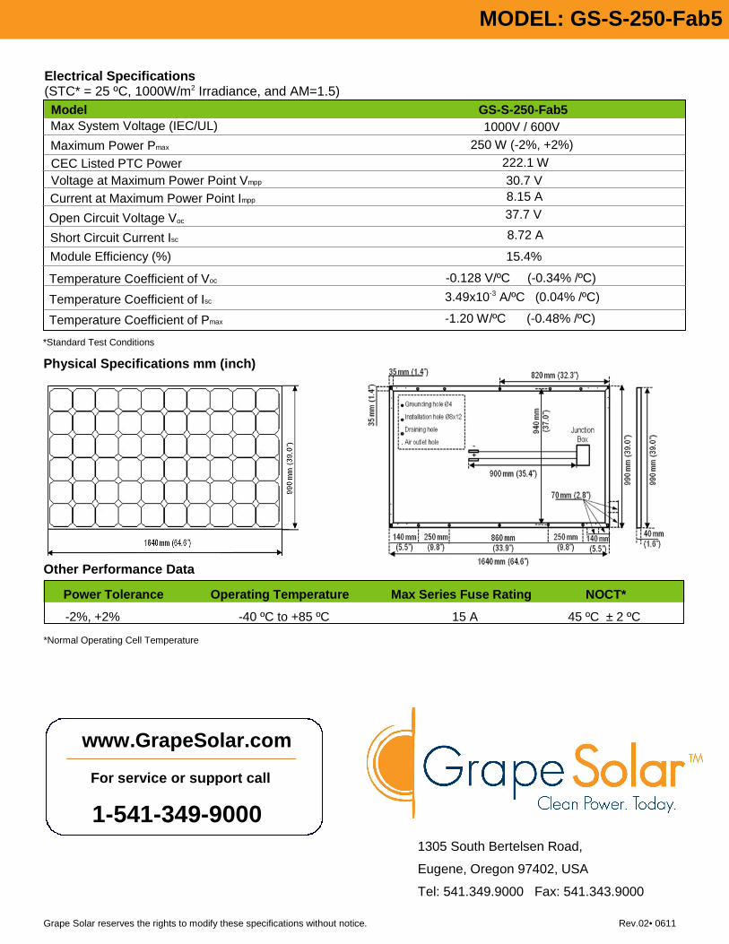
Module Dimension (L x W x T) 1640mm x 990mm x 40mm (64.6” x 39.0” x 1.6”)
No. of Cells 6 x 10 = 60
Weight 18.6 kg (41.0 lbs)
Cable Length 900mm (43.3”) for positive (+) and negative (-)
Type of Connector MC-IV
Junction Box IP65 or IP67 Rated
No. of Holes in Frame 4 draining holes, 8 installation holes, 2 grounding holes, 16 air outlet holes.
Mechanical Specifications
Rev.02• 0611
MODEL: GS-S-250-Fab5
Applications
• Any large or small on-grid /off-grid solar power stations. • Commercial/industrial building roof-top and ground systems. • Residential roof-top and ground systems.
Other Performance Data
Power Tolerance Operating Temperature Max Series Fuse Rating NOCT*
-2%, +2% -40 ºC to +85 ºC 15 A 45 ºC ± 2 ºC
1305 South Bertelsen Road,
Eugene, Oregon 97402, USA
Tel: 541.349.9000 Fax: 541.343.9000
Physical Specifications mm (inch)
Grape Solar reserves the rights to modify these specifications without notice. Rev.02• 0611
*Normal Operating Cell Temperature
Electrical Specifications (STC* = 25 ºC, 1000W/m2 Irradiance, and AM=1.5)
*Standard Test Conditions
www.GrapeSolar.com
For service or support call
1-541-349-9000
Model GS-S-250-Fab5 Max System Voltage (IEC/UL) 1000V / 600V
Maximum Power Pmax 250 W (-2%, +2%)
Voltage at Maximum Power Point Vmpp 30.7 V Current at Maximum Power Point Impp 8.15 A
Open Circuit Voltage Voc 37.7 V
Short Circuit Current Isc 8.72 A
Temperature Coefficient of Voc -0.128 V/ºC (-0.34% /ºC)
Temperature Coefficient of Isc 3.49x10⁻³ A/ºC (0.04% /ºC)
Temperature Coefficient of Pmax -1.20 W/ºC (-0.48% /ºC)
MODEL: GS-S-250-Fab5
CEC Listed PTC Power 222.1 W
Module Efficiency (%) 15.4%
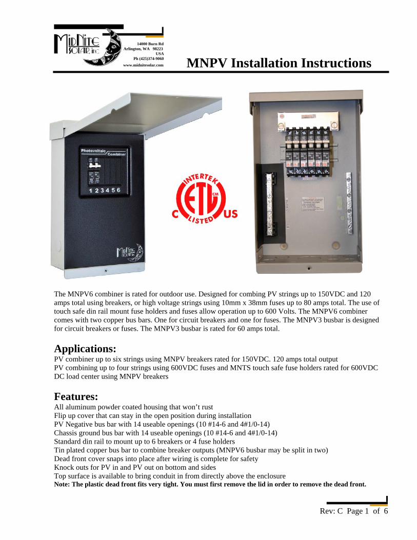
14000 Burn RdArlington, WA 98223
USAPh (425)374-9060
www.midnitesolar.com MNPV Installation Instructions
Rev: C Page 1 of 6
The MNPV6 combiner is rated for outdoor use. Designed for combing PV strings up to 150VDC and 120 amps total using breakers, or high voltage strings using 10mm x 38mm fuses up to 80 amps total. The use of touch safe din rail mount fuse holders and fuses allow operation up to 600 Volts. The MNPV6 combiner comes with two copper bus bars. One for circuit breakers and one for fuses. The MNPV3 busbar is designed for circuit breakers or fuses. The MNPV3 busbar is rated for 60 amps total. Applications: PV combiner up to six strings using MNPV breakers rated for 150VDC. 120 amps total output PV combining up to four strings using 600VDC fuses and MNTS touch safe fuse holders rated for 600VDC DC load center using MNPV breakers Features: All aluminum powder coated housing that won’t rust Flip up cover that can stay in the open position during installation PV Negative bus bar with 14 useable openings (10 #14-6 and 4#1/0-14) Chassis ground bus bar with 14 useable openings (10 #14-6 and 4#1/0-14) Standard din rail to mount up to 6 breakers or 4 fuse holders Tin plated copper bus bar to combine breaker outputs (MNPV6 busbar may be split in two) Dead front cover snaps into place after wiring is complete for safety Knock outs for PV in and PV out on bottom and sides Top surface is available to bring conduit in from directly above the enclosure Note: The plastic dead front fits very tight. You must first remove the lid in order to remove the dead front.
MNPV Installation Instructions (continued)
Rev: C Page 2 of 6
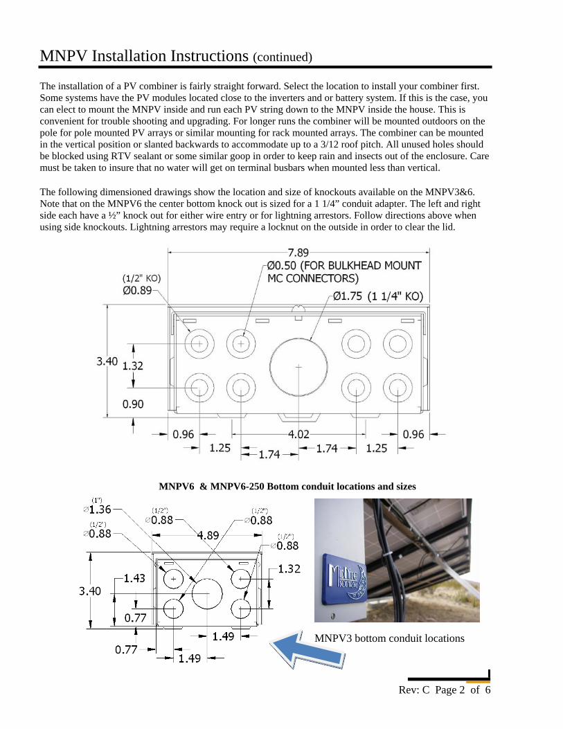
The installation of a PV combiner is fairly straight forward. Select the location to install your combiner first. Some systems have the PV modules located close to the inverters and or battery system. If this is the case, you can elect to mount the MNPV inside and run each PV string down to the MNPV inside the house. This is convenient for trouble shooting and upgrading. For longer runs the combiner will be mounted outdoors on the pole for pole mounted PV arrays or similar mounting for rack mounted arrays. The combiner can be mounted in the vertical position or slanted backwards to accommodate up to a 3/12 roof pitch. All unused holes should be blocked using RTV sealant or some similar goop in order to keep rain and insects out of the enclosure. Care must be taken to insure that no water will get on terminal busbars when mounted less than vertical. The following dimensioned drawings show the location and size of knockouts available on the MNPV3&6. Note that on the MNPV6 the center bottom knock out is sized for a 1 1/4” conduit adapter. The left and right side each have a ½” knock out for either wire entry or for lightning arrestors. Follow directions above when using side knockouts. Lightning arrestors may require a locknut on the outside in order to clear the lid. MNPV6 & MNPV6-250 Bottom conduit locations and sizes
MNPV3 bottom conduit locations
MNPV Installation Instructions (continued)
Rev: C Page 3 of 6
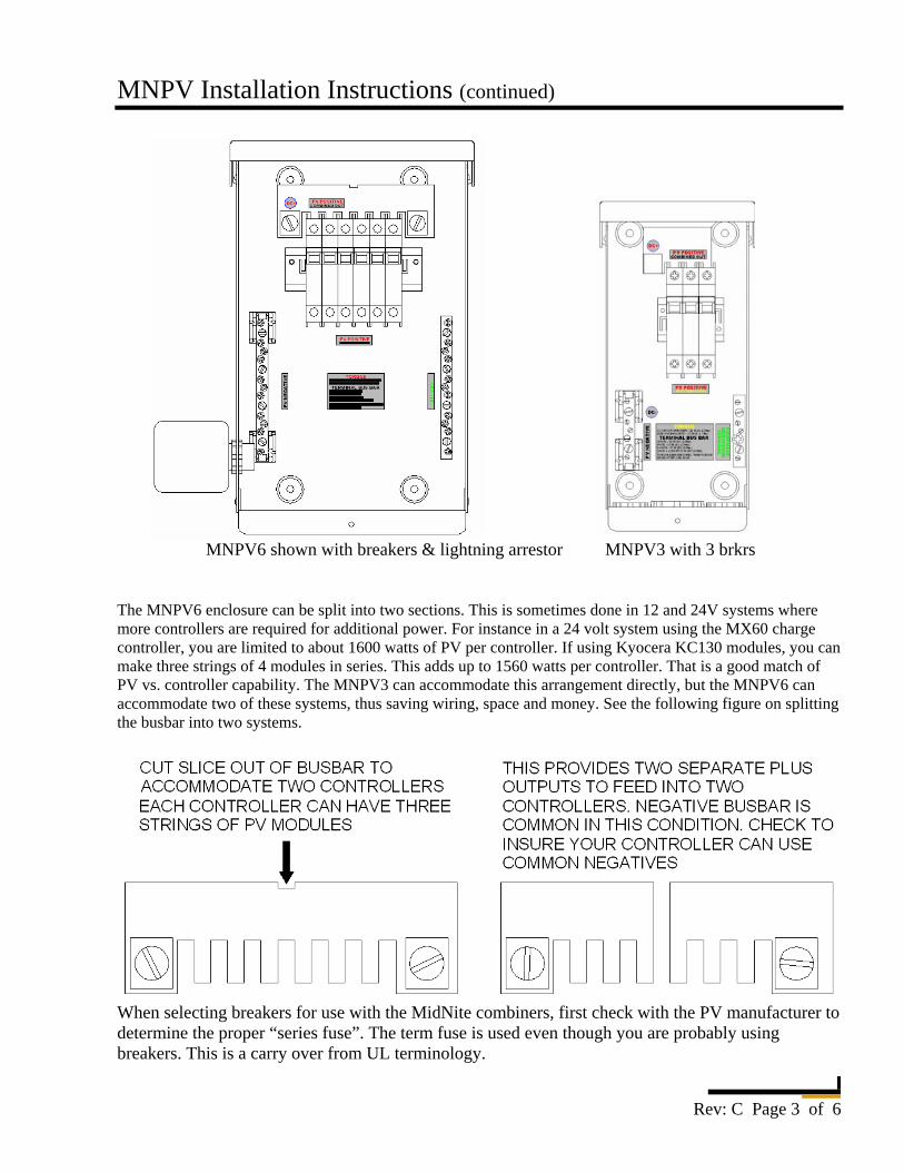
MNPV6 shown with breakers & lightning arrestor MNPV3 with 3 brkrs The MNPV6 enclosure can be split into two sections. This is sometimes done in 12 and 24V systems where more controllers are required for additional power. For instance in a 24 volt system using the MX60 charge controller, you are limited to about 1600 watts of PV per controller. If using Kyocera KC130 modules, you can make three strings of 4 modules in series. This adds up to 1560 watts per controller. That is a good match of PV vs. controller capability. The MNPV3 can accommodate this arrangement directly, but the MNPV6 can accommodate two of these systems, thus saving wiring, space and money. See the following figure on splitting the busbar into two systems.
When selecting breakers for use with the MidNite combiners, first check with the PV manufacturer to determine the proper “series fuse”. The term fuse is used even though you are probably using breakers. This is a carry over from UL terminology.
MNPV Installation Instructions (continued)
Rev: C Page 4 of 6
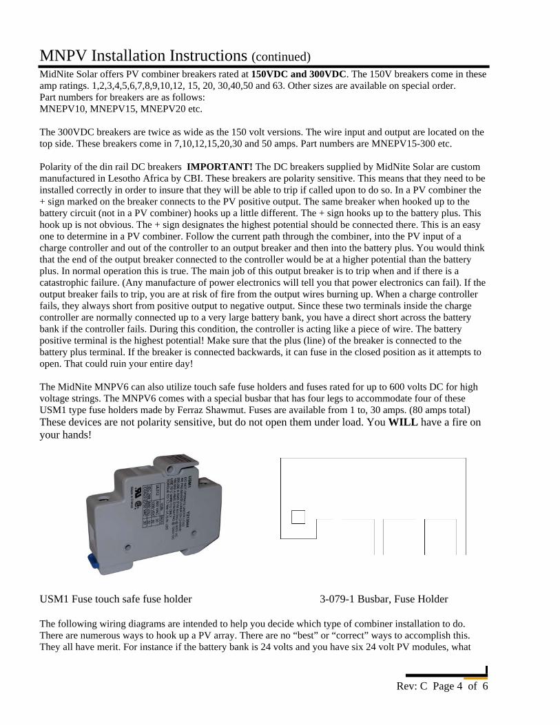
MidNite Solar offers PV combiner breakers rated at 150VDC and 300VDC. The 150V breakers come in these amp ratings. 1,2,3,4,5,6,7,8,9,10,12, 15, 20, 30,40,50 and 63. Other sizes are available on special order. Part numbers for breakers are as follows: MNEPV10, MNEPV15, MNEPV20 etc. The 300VDC breakers are twice as wide as the 150 volt versions. The wire input and output are located on the top side. These breakers come in 7,10,12,15,20,30 and 50 amps. Part numbers are MNEPV15-300 etc. Polarity of the din rail DC breakers IMPORTANT! The DC breakers supplied by MidNite Solar are custom manufactured in Lesotho Africa by CBI. These breakers are polarity sensitive. This means that they need to be installed correctly in order to insure that they will be able to trip if called upon to do so. In a PV combiner the + sign marked on the breaker connects to the PV positive output. The same breaker when hooked up to the battery circuit (not in a PV combiner) hooks up a little different. The + sign hooks up to the battery plus. This hook up is not obvious. The + sign designates the highest potential should be connected there. This is an easy one to determine in a PV combiner. Follow the current path through the combiner, into the PV input of a charge controller and out of the controller to an output breaker and then into the battery plus. You would think that the end of the output breaker connected to the controller would be at a higher potential than the battery plus. In normal operation this is true. The main job of this output breaker is to trip when and if there is a catastrophic failure. (Any manufacture of power electronics will tell you that power electronics can fail). If the output breaker fails to trip, you are at risk of fire from the output wires burning up. When a charge controller fails, they always short from positive output to negative output. Since these two terminals inside the charge controller are normally connected up to a very large battery bank, you have a direct short across the battery bank if the controller fails. During this condition, the controller is acting like a piece of wire. The battery positive terminal is the highest potential! Make sure that the plus (line) of the breaker is connected to the battery plus terminal. If the breaker is connected backwards, it can fuse in the closed position as it attempts to open. That could ruin your entire day! The MidNite MNPV6 can also utilize touch safe fuse holders and fuses rated for up to 600 volts DC for high voltage strings. The MNPV6 comes with a special busbar that has four legs to accommodate four of these USM1 type fuse holders made by Ferraz Shawmut. Fuses are available from 1 to, 30 amps. (80 amps total) These devices are not polarity sensitive, but do not open them under load. You WILL have a fire on your hands! USM1 Fuse touch safe fuse holder 3-079-1 Busbar, Fuse Holder The following wiring diagrams are intended to help you decide which type of combiner installation to do. There are numerous ways to hook up a PV array. There are no “best” or “correct” ways to accomplish this. They all have merit. For instance if the battery bank is 24 volts and you have six 24 volt PV modules, what
MNPV Installation Instructions (continued)
Rev: C Page 5 of 6
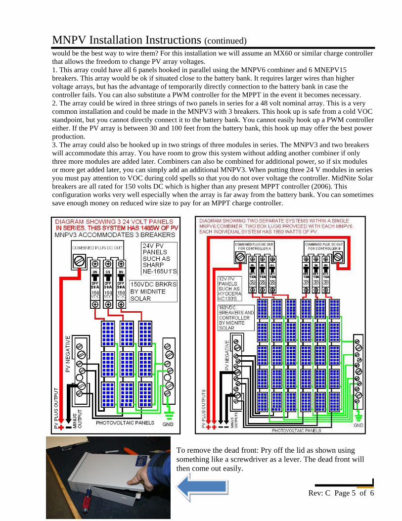
would be the best way to wire them? For this installation we will assume an MX60 or similar charge controller that allows the freedom to change PV array voltages. 1. This array could have all 6 panels hooked in parallel using the MNPV6 combiner and 6 MNEPV15 breakers. This array would be ok if situated close to the battery bank. It requires larger wires than higher voltage arrays, but has the advantage of temporarily directly connection to the battery bank in case the controller fails. You can also substitute a PWM controller for the MPPT in the event it becomes necessary. 2. The array could be wired in three strings of two panels in series for a 48 volt nominal array. This is a very common installation and could be made in the MNPV3 with 3 breakers. This hook up is safe from a cold VOC standpoint, but you cannot directly connect it to the battery bank. You cannot easily hook up a PWM controller either. If the PV array is between 30 and 100 feet from the battery bank, this hook up may offer the best power production. 3. The array could also be hooked up in two strings of three modules in series. The MNPV3 and two breakers will accommodate this array. You have room to grow this system without adding another combiner if only three more modules are added later. Combiners can also be combined for additional power, so if six modules or more get added later, you can simply add an additional MNPV3. When putting three 24 V modules in series you must pay attention to VOC during cold spells so that you do not over voltage the controller. MidNite Solar breakers are all rated for 150 volts DC which is higher than any present MPPT controller (2006). This configuration works very well especially when the array is far away from the battery bank. You can sometimes save enough money on reduced wire size to pay for an MPPT charge controller.
To remove the dead front: Pry off the lid as shown using something like a screwdriver as a lever. The dead front will then come out easily.
MNPV Installation Instructions (continued)
Rev: C Page 6 of 6
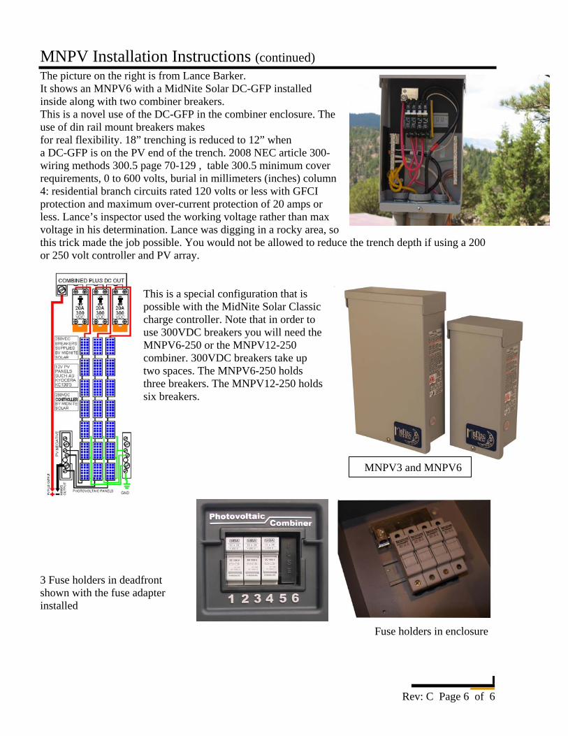
The picture on the right is from Lance Barker. It shows an MNPV6 with a MidNite Solar DC-GFP installed inside along with two combiner breakers. This is a novel use of the DC-GFP in the combiner enclosure. The use of din rail mount breakers makes for real flexibility. 18” trenching is reduced to 12” when a DC-GFP is on the PV end of the trench. 2008 NEC article 300- wiring methods 300.5 page 70-129 , table 300.5 minimum cover requirements, 0 to 600 volts, burial in millimeters (inches) column 4: residential branch circuits rated 120 volts or less with GFCI protection and maximum over-current protection of 20 amps or less. Lance’s inspector used the working voltage rather than max voltage in his determination. Lance was digging in a rocky area, so this trick made the job possible. You would not be allowed to reduce the trench depth if using a 200 or 250 volt controller and PV array.
This is a special configuration that is possible with the MidNite Solar Classic charge controller. Note that in order to use 300VDC breakers you will need the MNPV6-250 or the MNPV12-250 combiner. 300VDC breakers take up two spaces. The MNPV6-250 holds three breakers. The MNPV12-250 holds six breakers.
3 Fuse holders in deadfront shown with the fuse adapter installed
Fuse holders in enclosure
MNPV3 and MNPV6