Embed Size (px)
Citation preview

KCFPKompetenscentrum Förbränningsprocesser
Centre of Competence Combustion Processes
Annual Report 2009
Faculty of Engineering, LTH Lund University

1
KCFP Centre of Competence Combustion Processes
The centre of competence combustion processes, KCFP, started July 1 1995.
The main goal of this centre is to better understand the combustion process in internal combustion engines. Of particular interest are the combustion processes with low enough temperature to suppress formation of NOx and particulates, PM, often called Low Temperature Combustion, LTC or homogeneous Charge Compression Ignition, HCCI.
The centre of competence combustion processes has a budget of 23.9 MSEK per year. This is roughly one third each from the Swedish Energy Agency, STEM, Lund University and Industry.
INDUSTRY
PARTNERS
Volvo Cars
Volvo Powertrain
Volvo Penta
Saab/GM
Scania
Toyota
Nissan
Caterpillar
Cargine
Chevron
Finnveden
Hoerbiger (Former Mecel.)
Loge
Wärtsilä Diesel
The Swedish Gas Centre, SGC
CONTENTS
1. Partially Premixed Combustion Project 4
1.1. Gasoline Partially Premixed Combustion 4
1.2. Multiple Scattering Suppression in Planar Laser Imaging 7
1.3. Effect of Strong Pressure Oscillations on Wall Temperature 9
2. Spark Assisted Compression Ignition (SACI) 10
3. Combustion Control Project 12
3.1. A Physical Two-Zone NOx Model Intended for Embedded
Implementation 12
3.2. Predictive Control of HCCI 14
4. Modelling of HCCI Combustion 15
5. SI Gas Engine Project 17
6. THE Fuel 19
7. Generic Diesel Project 21
7.1. Sources of CO and UHC in a HSDI diesel engine during
Low-Temperature Combustion 21
7.2. Influence of Jet-Jet and Jet-Wall Interactions on the Lift-Off
Length in an Optical Heavy-Duty DI Diesel Engine 22
7.3. Time Resolved Soot Measurements in a Diesel Engine 23

2
KCFPORGANISATION
BOARD
Sören Udd, Volvo Powertrain (Chair)
Börje Grandin, Volvo Cars
Tommy Björkqvist, GM Sweden
Urban Johansson, Scania CV
Ulla Holst, LTH
Marcus Aldén, LTH
Per Tunestål, LTH
Bernt Gustavsson, STEM
DIRECTORProfessor
Bengt JohanssonSupervisor for:
PPC, SACI
ADMINISTRATOR
Maj-Lis Roos
AssociateProfessor
Mattias Richter
Supervisor for:PPC
AssociateProfessor
Per Tunestål
Supervisor for:CC , SIGE and
SACI
AssistantProfessor
Öivind Andersson
Supervisor for:GenDies
Associate Professor
Rolf Egnell
Supervisor for:Fuel, PPC, GenDies
ProfessorRolf Johansson
Supervisor for:CC
ProfessorXue-Song Bai
Supervisor for:CM
ProfessorMarcus Aldén
Supervisor for:PPC, SIGE,GenDies
AssistantProfessor
Martin Tunér
Supervisor for:Fuel
ADMINISTRATOR
Nina Mårtensson
3
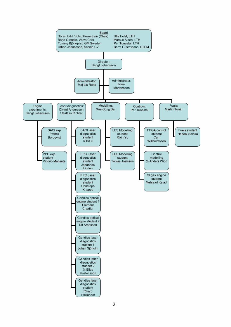
Board Sören Udd, Volvo Powertrain (Chair) Ulla Holst, LTH Börje Grandin, Volvo Cars Marcus Aldén, LTH Tommy Björkqvist, GM Sweden Per Tunestål, LTH Urban Johansson, Scania CV Bernt Gustavsson, STEM
Director: Bengt Johansson
Engine experiments:
Bengt Johansson
Laser diagnostics: Öivind Andersson / Mattias Richter
Modelling: Xue-Song Bai
Administrator: Maj-Lis Roos
Controls: Per Tunestål
SACI exp Patrick
Borgqvist
PPC exp. student Vittorio Manente
SACI laser diagnostics
student ¼ Bo Li
PPC Laser diagnostics
student Johannes
Lindén
Fuels: Martin Tunér
PPC Laser diagnostics
student Christoph Knappe
Gendies optical engine student 1
Clément Chartier
Gendies optical engine student 2
Ulf Aronsson
LES Modelling student Rixin Yu
LES Modelling student
Tobias Joelsson
FPGA control student
Carl Willhelmsson
Fuels student Hadeel Solaka
Gendies laser diagnostics student 1
Johan Sjöholm
Gendies laser diagnostics student 2 ½ Elias
Kristensson
Control modelling
½ Anders Widd
Administrator: Nina
Mårtensson
SI gas engine student
Mehrzad Kaiadi
Gendies laser diagnostics
student Rikard
Wellander

4
Introduction
Because emission regulations are getting tighter and the environmental concerns are increasing there is the need to develop high-ly efficient and low polluting internal com-bustion engines. Gasoline partially premixed combustion seems to be a viable candidate to accomplish this task.
By using in the whole load range 50% of EGR and λ between 1.3 and 1.5, it is always pos-sible to keep the maximum combustion tem-perature between 1500 and 2000 K (see Fi-gure 1) thus simultaneously reduce NOx and CO. Because 50% of EGR is used the boost level has to be increased thus the efficiency of the engine improves because of the simul-taneous reduction in exhaust loss and heat transfer. High boost also promotes low tem-perature reactions which are capable to re-duce the maximum rate of heat release thus the maximum pressure rise rate is lower. Soot is almost eliminated even when 50% of EGR is used. This is because gasoline mo-lecular structure is less prone than diesel to produce particulate for exactly the same inlet and combustion conditions.
Results
The double injection strategy developed in 2008 enabled to achieve relatively high effi-ciency, very low NOx and acceptable advan-tages achieved so far it was decided to limit the maximum load to 12 bar gross
Figure 1. Adiabatic flame temperature as a function
of EGR and λ calculated assuming constant volume combustion.
IMEP because with the compression ratio used in these experiments, 17.1, this was the limit to keep a certain separation between end of the injection and start of the combus-tion. λ and EGR were increased up to 1.4-1.5 and to 50% respectively for the reasons ex-plained in the Introduction. This new concept was tested using nine fuels in the gasoline boiling point range but with an octane num-ber between 99 and 70. The increase in boost and EGR allowed reaching 57% gross indica-ted efficiency for two fuels at roughly 8 bar IMEP. For loads higher than 6 bar IMEP all the fuels were showing at least 52% gross indica-ted efficiency; see Figure 2.
1. Partially Premixed Combustion ProjectPartially Premixed Combustion, PPC, is a combustion process between Homogeneous Charge Compression Ignition, HCCI and the classical diffusion controlled diesel combustion. With PPC it is possible to moderate the charge inhomogeneity and thus control the burn rate better than with HCCI. In comparison to classical diesel combustion the NOx and particulates can be suppressed with orders of magnitude.
Within the PPC project there have been substantial activities 2009 on PPC type of combustion with a range of fuels and engine types. The Ph.D. student, Vittorio Manente has been running a Scania truck size diesel engine with PPC type of combustion using diesel fuel as well as high octane fuels like gasoline and ethanol. Mixtures of diesel and ethanol and gasoline /ethanol were also tested. In contrast to the results presented in the annual report 2007 the engine has been operated with increased inlet pressure and hence load. Tests have also been conducted in a car size diesel engine, the Volvo D5, in collaboration with the fuels project. Late in the year laser experiments were carried out in the Scania D12 engine with laser induced phospho-rescence, LIP, on combustion chamber walls to investigate the wall heat transfer increase due to sever pressure oscillations that can occur with too homogeneous mixtures.
1.1. Gasoline Partially Premixed Combustion
Vittorio Manente
PhD Student
Johannes Lindén
PhD Student
Elias Kristensson
PhD Student

5
Figure 2. Gross indicated efficiency as a function of load a fuel type. Scania D12, high compression ratio.
NOx were low for all the fuels throughout the sweep while soot was mainly a function of the fuel octane number. At high load high oc-tane number fuels showed less than 0.5 FSN of smoke while with lower ON gasolines soot increased up to 5 FSN; see Figure 3.
To increase the upper load limit the com-pression ratio was decreased down to 14.3. As shown in Figure 4 it was not possible to reach again 57% gross indicated efficiency on the other hand this parameter was between 52 and 56% for all the fuels for loads higher than 8 bar gross IMEP. In this load sweep the EGR-λ combination was fine tuned and a maximum value of soot of 2 FSN was reached at 18 bar gross IMEP; see Figure 5 on the next page. At this point it was believed that soot could not be decreased unless using an up to date comon injection system (the one used in these experiments is a first prototype from Bosch). 50% of EGR enabled to keep NOx be-low 0.35 g/kWh at 18 bar IMEP.
Figure 4. Gross indicated efficiency as a function of load a fuel type. Scania D12, low compression ratio.
Because of limitations in the Scania D12 test cell, the gasoline PPC concept under exami-nation was studied in a modern Scania D13 that was equipped with an up to date injec-tion system. The maximum load was limited to 25 bar gross IMEP and gasoline fuels were
compared to diesel in a load sweep between 5 bar IMEP and maximum load. Figure 6 on the next page shows that it is possible to ac-hieve high efficiency simultaneously with low NOx in the whole load range independently on the fuel type. The major difference bet-ween gasoline type of fuels and diesel con-sists in the fact that diesel produces 10 times more soot than gasoline (independently on the octane number) because of its molecular structure; see Figure 7. With the up to date injection system used in this latest campaign at 20-25 bar IMEP the gasoline fuels showed a maximum value of 0.5 FSN in soot even when the relative excess of air was 1.3; see Figure 8.
Figure 3. Specific NOx and soot as a function of load a fuel type. Scania D12, high compression ratio.

6
Figure 6. Gross indicated efficiency vs. NOx for dif-ferent type of fuels from 5 to 25 bar gross IMEP.
Figure 8. Soot as a function of λ for different type of fuels at 20 and 25 bar gross IMEP.
Figure 7. Soot vs. NOx for different type of fuels from 5 to 25 bar gross IMEP.
Figure 5. Specific NOx and soot as a function of load a fuel type. Scania D12, low compression ratio.
Conclusions
This research showed that by using 50% of EGR and λ ~ 1.5 it is possible to achieve NOx below 0.35 g/kWh, gross indicated efficiency in the range of 53% and acceptable maximum pressure rise rate between 5 and 25 bar gross IMEP both using gasoline and diesel running in partially premixed combustion. The main difference between these two fuel categories is in the soot values. Because of its molecular structure diesel can produce up to 10 times more soot than gasoline for exactly the same running conditions. Because gasoline is less prone to produce particulate it is possible to run gasoline PPC using 1.3 as relative excess of air and producing at most 0.5 FSN of soot even when 50% of EGR is used.

7
Introduction
Non-intrusive laser based measurements for combustion studies have during the last de-cades displaced many of the more traditio-nal physical probe techniques, as these easily disturb the sample under study. One of the most commonly used laser based techniques for imaging purposes is a method known as laser sheet imaging or planar laser imaging.
The fundamental principle for this technique is to form a laser beam into a thin sheet (la-ser sheet) which is guided through the sam-ple of interest. By recording the generated signal (elastic or inelastic scattering) at 90 degrees using a camera, this can provide 2D information with high spatial and temporal (if the laser is pulsed) resolution of the il-luminated section. This approach provides reliable information as long as all the signal originates from the thin section that is illu-minated. If a signal is generated from other regions of the sample, this will falsely be in-terpreted as though it is originating from the cross section induced by the laser sheet. So, when does this unwanted effect occur? The answer to this question is that it depends on the optical characteristics of the sample.
The term optical thickness describes the turbidity - opacity - of sample. A low optical thickness implies that the incoming light in-teracts, on an average, less than once with the sample. All detected light can then be assumed to originate from the laser sheet. However, when the optical thickness in-crease light interacts, on an average, more than once with the sample. This phenomena is known as multiple scattering and simply means that the detected light may have been scattered several times while traveling within the sample. This leads to large uncertainties, as parts of the sample surrounding the laser sheet now also is probed. The most apparent error in these cases is that the image beco-mes blurred. Unfortunately, the light that has been multiply scattered varies over the entire image and one can therefore not re-move its contribution by applying a threshold on the recorded image. For this reason, mul-tiple scattering is considered to be the main source of error when probing optically thick
media, such as atomizing spray systems. Structured Laser Illumination Planar Imaging - SLIPI - is an imaging technique with which
this multiply scattered light is highly sup-pressed. This is achieved experimentally by “marking” the incoming light source. Such an approach allows light that interacts only once with the medium to be recognized (ide-ally), as this directly scattered light keeps the “mark”.
Figure 9. Example of an intensity modulated laser sheet.
Figure 9 shows an example of such a “mark” illumination scheme. Normally, a laser sheet consists of a homogeneous illumination. For SLIPI, this homogeneous light source is repla-ced by an intensity modulated laser sheet. This could be considered as a laser sheet fil-led with lines, where the line structure serves as the “tag”. Thus, some parts of the sample is illuminated, some parts are not. The im-portance here is that this approach allows prior knowledge of from where in space light should be scattered. Hence, light that is de-tected in between the lines must arise from multiple scattering and should be discarded. As some parts of the sample are not illumi-nated, the entire sample cannot be visualized with only one recording. To obtain the full in-formation the lines must be shifted vertically, which is the main drawback with SLIPI.
1.2. Multiple Scattering Suppression in Planar Laser Imaging
8
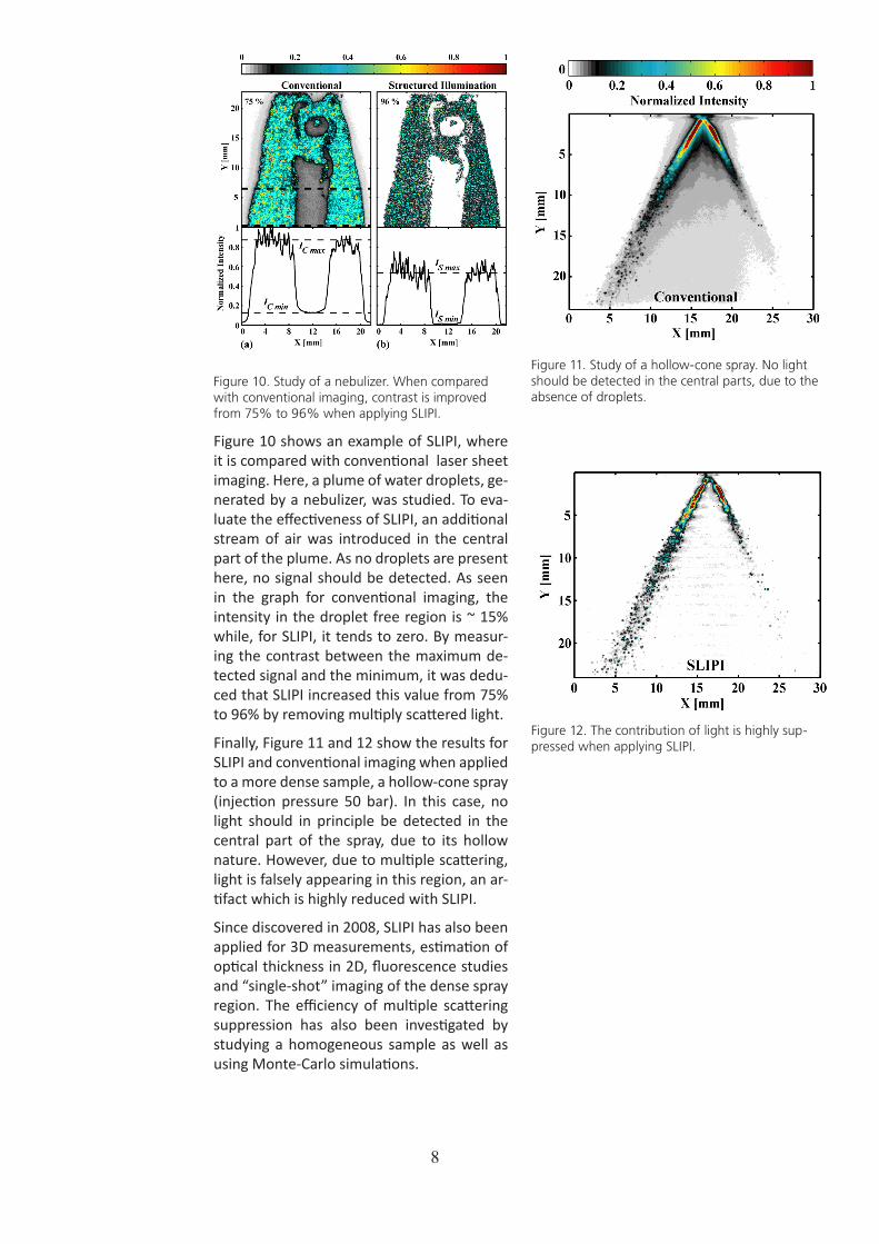
Figure 10. Study of a nebulizer. When compared with conventional imaging, contrast is improved from 75% to 96% when applying SLIPI.
Figure 10 shows an example of SLIPI, where it is compared with conventional laser sheet imaging. Here, a plume of water droplets, ge-nerated by a nebulizer, was studied. To eva-luate the effectiveness of SLIPI, an additional stream of air was introduced in the central part of the plume. As no droplets are present here, no signal should be detected. As seen in the graph for conventional imaging, the intensity in the droplet free region is ~ 15% while, for SLIPI, it tends to zero. By measur-ing the contrast between the maximum de-tected signal and the minimum, it was dedu-ced that SLIPI increased this value from 75% to 96% by removing multiply scattered light.
Finally, Figure 11 and 12 show the results for SLIPI and conventional imaging when applied to a more dense sample, a hollow-cone spray (injection pressure 50 bar). In this case, no light should in principle be detected in the central part of the spray, due to its hollow nature. However, due to multiple scattering, light is falsely appearing in this region, an ar-tifact which is highly reduced with SLIPI.
Since discovered in 2008, SLIPI has also been applied for 3D measurements, estimation of optical thickness in 2D, fluorescence studies and “single-shot” imaging of the dense spray region. The efficiency of multiple scattering suppression has also been investigated by studying a homogeneous sample as well as using Monte-Carlo simulations.
Figure 11. Study of a hollow-cone spray. No light should be detected in the central parts, due to the absence of droplets.
Figure 12. The contribution of light is highly sup-pressed when applying SLIPI.

9
Introduction
In the PPC project it has been noted that se-vere pressure oscillations at high load have a strong negative effect on the efficiency. In this PPC sub-project the in-cylinder wall tem-perature will be measured in order to investi-gate the high pressure oscillations ability to break the thermal boundary layer and thus enhancing heat transfer.
The chosen technique is based on what is re-ferred to as thermographic phosphors. This is an optical technique that is non intrusive and capable of remote probing.
In short: The surface of interest is coated with a thin layer of a suitable thermo sen-sitive material (thermographic phosphor). Then the coating is illuminated with laser radiation and shortly thereafter, when the excited material relaxes, light is emitted. This resulting radiation from most thermographic phosphors has a lifetime which is dependent upon the temperature. The intensity decays exponentially in accordance with where
I =I0e-t/τ
I0 is the initial emission intensity, t is time and τ is the lifetime time constant of the phospho-rescence involved i.e. the time taken for the intensity to decrease to 1/e of the initial emis-sion I0. The phosphorescence lifetime of the phosphor material decrease with increasing temperature. The temperature can thus be calibrated to the lifetime and be reproduced by calculating the phosphorescence lifetime from the measured decay in intensity. This is normally done by fitting the intensity decay to the theoretical model, using a non-linear fitting procedure. The error in temperature in such a measurement is ideally less than 1%. In the ongoing measurement campaign ther-mographic phosphor CdWO4 is being used. This phosphor emits blue light which makes it less sensitive to interferences from soot ra-diation. The lifetime is shorter which enables even higher time resolution <2μs. Further-more the signal strength is also enhanced compared to the previous used material.
Preliminary results
The lifetime of a phosphor can vary seve-ral orders of magnitude with temperature. Finding a stable method for associating life-times with temperatures during calibration is crucial to the accuracy and reliability of the time-based phosphor thermometry techni-que. An iterative fitting algorithm has been developed. Confidence intervals have been implemented for the first time allowing to evaluate the calibration uncertainty at a gi-ven temperature/lifetime, see Figure 13.
Figure 13. Lifetime versus temperature for CdWO4, including confidence intervals. Horizontal error bars indicate standard deviations from 100 recorded samples each and vertical error bars correspond to temperature uncertainties from thermocouples and temperature drifts during calibration.
So far preliminary tests have been performed in an optical engine, i.e. allowing optical ac-cess through quartz glass windows. Under these conditions, one is restricted to low loads, due to the risk of breaking the glass running on high loads. To be able to measure during high loads, access much be achieved using optical fibers, both for excitation of the phosphor and for detection of the phospho-rescence. The development of the design of this experiment are ongoing. Figure 2 and 3 shows the fiber mounts for the engine and for the detecting photo multiplier tube (PMT), respectively.
1.3. Effect of Strong Pressure Oscillations on Wall Temperature

10
Introduction
Spark Ignition (SI) engines struggle with low efficiency at part load operation. A feasible way to improve low load efficiency for cars currently running with SI engines would be to use an engine that can run in homogenous charge compression ignition (HCCI) mode at part load and switch to SI at high load. Stu-dies have reported high efficiency and low NOx emissions compared to the SI-engine. To achieve mode switching from SI to HCCI and vice versa the intermediate region where both combustion modes coexist i.e. SACI combustion is of interest and is the main tar-get for this project. Also the usage of spark assistance is of interest to control combus-tion timing and to increase the possible ope-rating range in HCCI mode.
Research
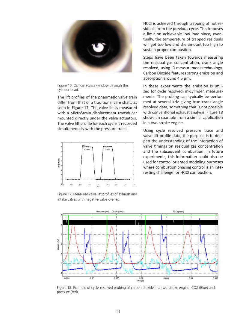
The research engine, seen in Figure 15, is a passenger car size Volvo D5 which has been converted to single cylinder operation. The CI cylinder head has been replaced by a pent-roof 4 valve SI cylinder head with optical ac-cess. Optical access is achieved through an, approximately, 20 mm diameter sapphire window, as seen in Figure 16. The spark plug can be seen in the center of the window.
Figure 15. The Volvo D5 research engine with opti-
cal access.
The engine is equipped with a combined spark plug and pressure sensor, port fuel injector and a fully flexible pneumatic valve train system supplied by Cargine Engineering. The valve train system consists of four actua-tors, one for each valve, fitted directly on top of the valve stem. The valve train system is working with pressurized air to achieve valve lift.
2. Spark Assisted Compression Ignition (SACI)
Figure 14, left image: Fiber holders for the engine (right holder) and for the PMT (left holder). The engine holder has room for 1-3 excitation fibers and 8 detection fibers.
Right image: The mount for the holder on the end of the 8 fibers detecting the phosphorescence, and how it’s fitted with the detecting PMT.
Patrick Borgqvist
PhD Student
11
Figure 16. Optical access window through the cylinder head.
The lift profiles of the pneumatic valve train differ from that of a traditional cam shaft, as seen in Figure 17. The valve lift is measured with a MicroStrain displacement transducer mounted directly under the valve actuators. The valve lift profile for each cycle is recorded simultaneously with the pressure trace.
Figure 17. Measured valve lift profiles of exhaust and
intake valves with negative valve overlap.
HCCI is achieved through trapping of hot re-siduals from the previous cycle. This imposes a limit on achievable low load since, even-tually, the temperature of trapped residuals will get too low and the amount too high to sustain proper combustion.
Steps have been taken towards measuring the residual gas concentration, crank angle resolved, using IR measurement technology. Carbon Dioxide features strong emission and absorption around 4.5 μm.
In these experiments the emission is utili-zed for cycle resolved, in-cylinder, measure-ments. The probing can typically be perfor-med at several kHz giving true crank angle resolved data, something that is not possible with conventional exhaust analysis. Figure 18 shows an example from a similar application in a two-stroke engine.
Using cycle resolved pressure trace and valve lift profile data, the purpose is to dee-pen the understanding of the interaction of valve timings on residual gas concentration and the subsequent combustion. In future experiments, this information could also be used for control oriented modeling purposes where combustion phasing control is an inte-resting challenge for HCCI combustion.
Figure 18. Example of cycle-resolved probing of carbon dioxide in a two-stroke engine. CO2 (Blue) and pressure (red).

12
In the automotive industry models are com-monly used mainly for three purposes; cali-bration, analysis and control. A NOx model which is intended for engine control has been developed, implemented and tested. For feedback control computational ease is much more important than maximal ac-curacy and full physical interpretation. Phy-sical models of different kinds can be used for engine control. Physical models are often preferred over ’black-box’ (empirical) models due to their more general nature. If a model successfully captures physical phenomena common for, in this case, engines, the model calibration effort hopefully decreases when adopting the model in different contexts (on different engines). Physical models can often be used both for prediction and indirect me-asurement.
The model, or algorithm, developed imple-ments a physically correct NO model which use a two zone approach to model the stra-tified nature of Diesel combustion. There is one burned zone in which the NOx formation takes place and one unburned zone com-posed of only air, as explained by Figure 19. Using this method and algorithm the physical interpretation can be maintained while the algorithm is significantly simplified.
If the pressure in the cylinder is known (which is a basic condition for much combus-tion engine related modeling) it is possible to compute the global temperature as well as the temperature of the unburned zone using a number of assumptions. Furthermore it is possible to compute the number of moles in the burned zone using ’conventional’ heat release analysis. It is also possible to compu-te the total number of moles in the combus-tion chamber and hence the number of
Figure 19. A two-zone modeling concept.
moles in the unburned zone. When the num-ber of moles in the unburned zone, burned zone and globally is known as well as the temperature globally and in the unburned zone it is possible to compute the temperatu-re of the burned zone. A more extensive mo-del of the combustion is hence not needed to compute the temperature of the burned zone. It is possible to avoid a direct compu-tation of burned zone temperature and the related complex and iterative numerical so-lution of an energy balance ’normally’ used to determine burned zone temperature and mole content.
Since NOx emissions mainly consist of NO, NO is modeled rather than NOx. NO forma-tion results from high temperatures in the burned gases created by combustion, hence the temperature of the combustion products (the burned zone) is a key variable for com-puting NO emissions. The methods for com-puting NO knowing the burned zone tem-perature are fairly well known and straight forward. To compute the NO formation rate
3 Combustion Control Project
3.1. A Physical Two-Zone NOx Model Intended For Embedded Implementation
The Control Project within KCFP focuses on control and control oriented modeling of com-bustion. Two PhD students, Anders Widd (Dept. of Automatic Control) and Carl Wilhelmsson (Dept. of Energy Sciences), are active in the project under supervision of senior researchers Per Tunestål (Energy Sciences) and Rolf Johansson (Control).
During the year a computationally efficient NOx model for Diesel combustion has been adap-ted for embedded implementation and subsequently implemented on an embedded system. Hybrid control (switching models) of HCCI combustion based on a physical model of combus-tion and heat transfer has also been developed and experimentally validated.Carl Wilhelmsson
PhD Student
Anders Widd
PhD Student

13
a novel variant of the well known ’Zeldovich’ rate expression (here called the ’modified’ Zeldovic rate) was developed and used. The original Zeldovich rate had to be corrected for varying burned zone volume.
Figure 20. Modeled NO content of the cylinder as a function of crank angle.
The performance of the model has been screened showing that the model gives suf-ficiently accurate results considering the coarse nature of the model. On five data points an absolute average error of 20% was obtained, the maximum error using a fixed local lambda of 1.088 was about 30%. Even though this number is not to be considered as a very good result compared to extensive multi-zone models it is, using the model, pos-sible to get quantitative information regar-ding the instantaneous NO content in the cy-linder. This work should be understod in the context of control oriented, on-board (em-bedded) implementable models. Comparing with complex multi-zone models is irrelevant considering the computation times needed to complete the different models. Using the suggested algorithm with pre-computed parts it is most likely possible to obtain infor-mation regarding the NO content during the cycle! Information that might prove useful when implementing for example feedback Diesel combustion control.
To be able to develop an in-cycle NO algo-rithm which could be computed on-line seve-ral changes had to be made compared to the original model. A causal version of the heat release (which does not depend on future values) had to be developed. The resulting causal heat release only differed a few per-cent from the non-causal one. The heat re-lease was normalized to the injected amount of fuel based on values from the four
Figure 21. Upper part show 90 cycles average NO formation rate, C algorithm compared to golden model. Lower part show corresponding global concentration of NO .
previous cycles. In order to obtain high com-putation speeds the NO formation rate had to be tabulated as a function of pressure ratio, current NO concentration and current burned zone temperature. Two different ver-sions of the algorithm were developed, one version using floating-point numbers and one version using fixed-point numbers. The resulting algorithms were implemented in C and tested on an embedded processor, ex-ecution times were measured and evaluated. The fixed-point algorithm proved to be able to compute in-cycle NO concentration ’on-line’ up to an engine speed of at least 3000 rpm and with a resolution of 0.2 CAD.
The floating-point version, being less than half as fast due to the use of floating point arithmetics, could do the same up to engine speeds of about 1000 rpm. Even though the model used fairly large tables it did not con-sume a lot of memory. The present model implementation occupies a total of 0.65 MB of memory. The output of the implemented algorithm showed good agreement to the output of the original NO model. A large part of the methodology used are applicable in other situations where it is desirable to im-plement fast versions of physical models in embedded environments. This work can be said to over bridge the traditional gap bet-ween the detailed physical models and the less detailed, state based, control oriented models.
280 300 320 340 360 380 400 420 4400
100
200
300
400
500
600Global NO concentration
c NO [
ppm]
a [CAD]
330 340 350 360 370 380 390 400 4100
2
4
6
x 10−4 Burned zone NO formation rate
a [CAD]
¶cNO/ ¶t
[mol
/cm
3 s]
golden m.ARM C floatARM C fix32
330 340 350 360 370 380 390 400 4100
100
200
300
400
500Global NO frac.
a [CAD]
X NO [
ppm]
golden m.ARM C floatARM C fix32
14
Introduction
The focus of this project is model-based control of HCCI. Physics-based models are favored due to the improved portability of the resulting controllers as well as the added insight into the physical process. A second-order model of HCCI has been developed previously in the project. The model relates the temperature state of the cylinder wall and the gas charge to the crank angle of au-toignition. The model has been used to de-sign Model Predictive Controllers (MPC) that have been evaluated in experiments. The ba-sic idea of MPC is to find a sequence of future control signals that minimize a cost function penalizing the predicted future output er-rors and control usage. The minimization is performed while respecting constraints on both inputs and outputs. Once the optimal control sequence has been found, the first step of the sequence is implemented. At the next sample, the optimization is repeated with the current state as initial condition, yielding a new control signal sequence.
The controllers used the inlet air tempera-ture and the crank angle of inlet valve closing as controllers and were designed based on linearizations of the nonlinear model. The resulting controllers were evaluated experi-mentally in terms of the response time to set point changes, steady-state output variance, and the robustness to disturbances. During experiments, the controller maintained the desired combustion phasing through chan-ges in engine speed, the amount of injected fuel, and the amount of recycled exhaust ga-ses. The steady-state output variance could be decreased by approximately 10% around certain operating points by changing to a li-nearization performed closer to that opera-ting point.
Hybrid Control of Exhaust Recom-pression HCCI
During the fall the use of multiple lineariza-tions was investigated further and experi-mentally evaluated on exhaust recompressi-on HCCI. The main motivation for considering controllers based on multiple linearizations is analysis showing that the dynamics of ex-haust recompression HCCI change qualitati-
vely with combustion phasing. As previously mentioned, experimental results obtained within this project has also shown improved performance with varying linearization point. The principle of exhaust recompression HCCI is to close the exhaust valve early and thus trap hot residuals in the cylinder. This yields an increase in the charge temperature and a reduced oxygen concentration in the fol-lowing cycle. The control signal considered in the experiments was the crank angle of exhaust valve closing, θEVC, and the control-led output was the crank angle of 50% fuel burned, θ50.
Depending on the charge temperature, one of thee different linearizations was used which improved the model accuracy conside-rably. This yields a model with three regions with linear dynamics within each region. The regions corresponded to early phasing (ear-lier than approximately two degrees after top dead center), late phasing (later than approximately seven degrees after top dead center), and a middle region. The differences between the regions were mainly in how the charge temperature was affected by the tem-perature in the previous cycle. At late com-bustion phasing, a high temperature will re-sult in a decrease in the next cycle generating an oscillatory behavior. The early phasing re-gion does not exhibit oscillations but rather a smooth transient. In the middle region, the dependence on the charge temperature in the previous cycle is diminished yielding a more robust response.
Two control structures were evaluated in ex-periments: state feedback control and MPC. The state feedback controller consisted of a feedforward- and a feedback part. The feed-back gain was selected based on the current estimate of the charge temperature while the feedforward gain was selected to match the next active region. The MPC was desig-ned so that it penalized the predicted error in combustion phasing and changes in ex-haust valve timing over the next two engine cycles. The predictions were made using the three-region model. The advantage of MPC in this case is that it predicts and compensa-tes for the differences in dynamics between
3.2. Predictive Control of HCCI
15
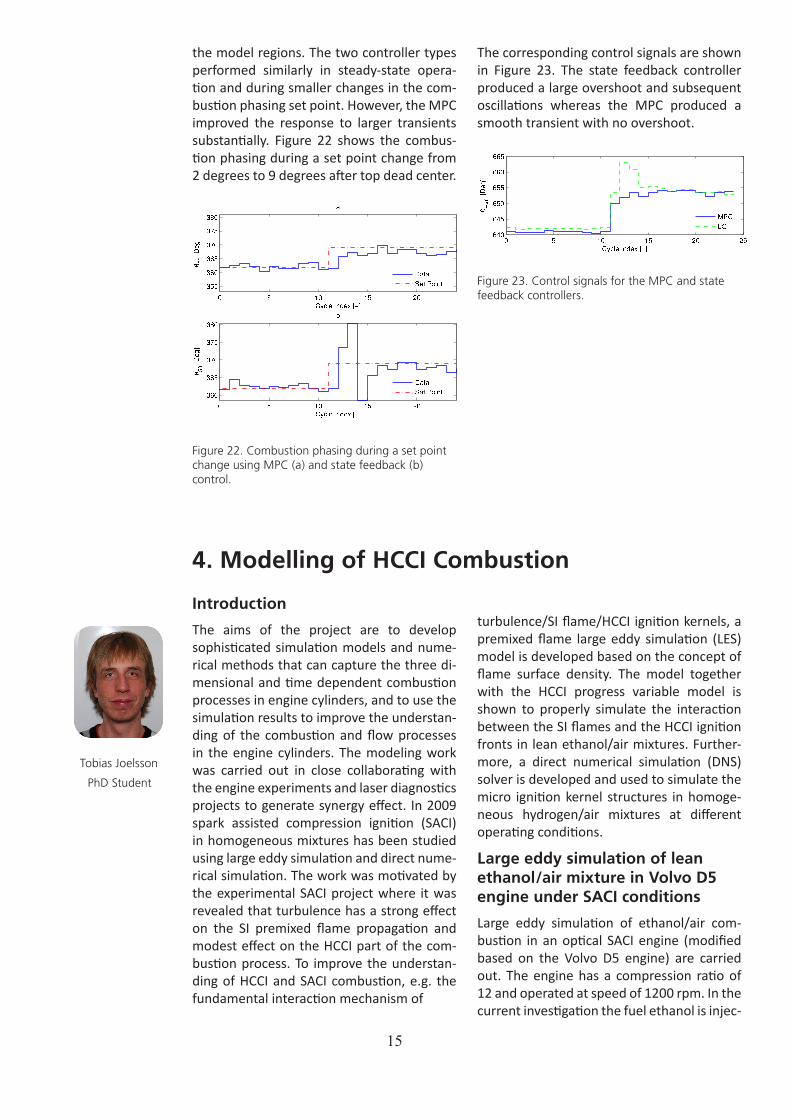
the model regions. The two controller types performed similarly in steady-state opera-tion and during smaller changes in the com-bustion phasing set point. However, the MPC improved the response to larger transients substantially. Figure 22 shows the combus-tion phasing during a set point change from 2 degrees to 9 degrees after top dead center.
Figure 22. Combustion phasing during a set point change using MPC (a) and state feedback (b) control.
Introduction
The aims of the project are to develop sophisticated simulation models and nume-rical methods that can capture the three di-mensional and time dependent combustion processes in engine cylinders, and to use the simulation results to improve the understan-ding of the combustion and flow processes in the engine cylinders. The modeling work was carried out in close collaborating with the engine experiments and laser diagnostics projects to generate synergy effect. In 2009 spark assisted compression ignition (SACI) in homogeneous mixtures has been studied using large eddy simulation and direct nume-rical simulation. The work was motivated by the experimental SACI project where it was revealed that turbulence has a strong effect on the SI premixed flame propagation and modest effect on the HCCI part of the com-bustion process. To improve the understan-ding of HCCI and SACI combustion, e.g. the fundamental interaction mechanism of
The corresponding control signals are shown in Figure 23. The state feedback controller produced a large overshoot and subsequent oscillations whereas the MPC produced a smooth transient with no overshoot.
Figure 23. Control signals for the MPC and state feedback controllers.
turbulence/SI flame/HCCI ignition kernels, a premixed flame large eddy simulation (LES) model is developed based on the concept of flame surface density. The model together with the HCCI progress variable model is shown to properly simulate the interaction between the SI flames and the HCCI ignition fronts in lean ethanol/air mixtures. Further-more, a direct numerical simulation (DNS) solver is developed and used to simulate the micro ignition kernel structures in homoge-neous hydrogen/air mixtures at different operating conditions.
Large eddy simulation of lean ethanol/air mixture in Volvo D5 engine under SACI conditions
Large eddy simulation of ethanol/air com-bustion in an optical SACI engine (modified based on the Volvo D5 engine) are carried out. The engine has a compression ratio of 12 and operated at speed of 1200 rpm. In the current investigation the fuel ethanol is injec-
4. Modelling of HCCI Combustion
Tobias Joelsson
PhD Student
16
ted at the intake port. Negative valve overlap (NVO) was used to have large amount of re-sidual gas kept in the cylinder. The IVO is at 60 CAD and EVC at 660 CAD. At different NVO conditions IVC and EVO were kept at 200 CAD and 520 CAD, respectively. The specific air/fuel ratio (lambda) is 1.3. Detailed chemi-cal reaction mechanisms of Marinov are used in the simulations.
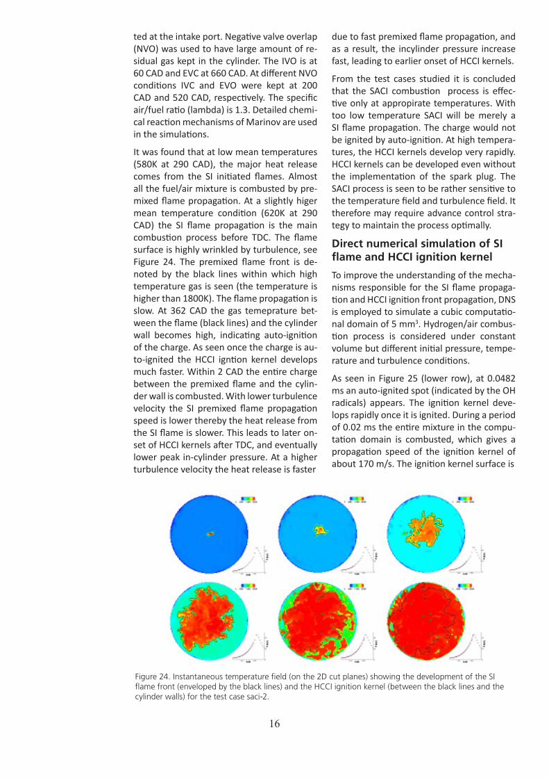
It was found that at low mean temperatures (580K at 290 CAD), the major heat release comes from the SI initiated flames. Almost all the fuel/air mixture is combusted by pre-mixed flame propagation. At a slightly higer mean temperature condition (620K at 290 CAD) the SI flame propagation is the main combustion process before TDC. The flame surface is highly wrinkled by turbulence, see Figure 24. The premixed flame front is de-noted by the black lines within which high temperature gas is seen (the temperature is higher than 1800K). The flame propagation is slow. At 362 CAD the gas temeprature bet-ween the flame (black lines) and the cylinder wall becomes high, indicating auto-ignition of the charge. As seen once the charge is au-to-ignited the HCCI igntion kernel develops much faster. Within 2 CAD the entire charge between the premixed flame and the cylin-der wall is combusted. With lower turbulence velocity the SI premixed flame propagation speed is lower thereby the heat release from the SI flame is slower. This leads to later on-set of HCCI kernels after TDC, and eventually lower peak in-cylinder pressure. At a higher turbulence velocity the heat release is faster
due to fast premixed flame propagation, and as a result, the incylinder pressure increase fast, leading to earlier onset of HCCI kernels.
From the test cases studied it is concluded that the SACI combustion process is effec-tive only at appropirate temperatures. With too low temperature SACI will be merely a SI flame propagation. The charge would not be ignited by auto-ignition. At high tempera-tures, the HCCI kernels develop very rapidly. HCCI kernels can be developed even without the implementation of the spark plug. The SACI process is seen to be rather sensitive to the temperature field and turbulence field. It therefore may require advance control stra-tegy to maintain the process optimally.
Direct numerical simulation of SI flame and HCCI ignition kernel
To improve the understanding of the mecha-nisms responsible for the SI flame propaga-tion and HCCI ignition front propagation, DNS is employed to simulate a cubic computatio-nal domain of 5 mm3. Hydrogen/air combus-tion process is considered under constant volume but different initial pressure, tempe-rature and turbulence conditions.
As seen in Figure 25 (lower row), at 0.0482 ms an auto-ignited spot (indicated by the OH radicals) appears. The ignition kernel deve-lops rapidly once it is ignited. During a period of 0.02 ms the entire mixture in the compu-tation domain is combusted, which gives a propagation speed of the ignition kernel of about 170 m/s. The ignition kernel surface is
Figure 24. Instantaneous temperature field (on the 2D cut planes) showing the development of the SI flame front (enveloped by the black lines) and the HCCI ignition kernel (between the black lines and the cylinder walls) for the test case saci-2.

17
rather smooth. The OH radicals inside the ig-nition kernel are rather uniform, with a mole fraction of OH radicals about 0.0156 (cor-responding to the dark green color). Turbu-lence eddies do not exert much wrinkling on the surface of the ignition kernel.
Introduction
Heavy duty Spark Ignition (SI) Natural Gas (NG) engines have lower efficiency than the heavy duty Diesel engines due to partly the lower compression ratio used in NG engines and also the throttling losses especially at low/part loads. The maximum load is also li-mited in SI NG engines due to higher exhaust gas temperature and also lower compression ratio. The main objective of this project is to approach Diesel engine efficiency; Diesel engine maximum load range and SI engine emission levels. High EGR rates combined with turbocharging has been identified as a promising way to increase the maximum load and efficiency of heavy duty SI NG engi-nes. With stoichiometric conditions a three way catalyst can be used and thus regulated emissions can be kept at very low levels. High dilution requires closed loop combustion control. It is also desired to increase the re-liability of the engine during transient opera-tion. The project has focused on applying
speed about 10 m/s. The highly wrinkled fla-me front is a result of turbulence eddy inte-raction on the surface and most importantly the effect of differential diffusion.
cylinder pressure and ion current based control in order to ensure stable operation at the dilution limit thereby maximizing the efficiency. New methods to determine com-bustion stability during transients have been developed and used together with model ba-sed control methods. New modifications are also performed on the engine to increase the overall efficiency and extend the maximum load limit.
Objectives
Since the start of this phase of the project some studies are performed and they are resulted in publishing four papers so far. The improvements are mainly made on engine transient reliability and decreasing throttling losses at low/part loads. The main objectives of the project during 2009 and afterwards are to improve the overall engine efficiency and also extend the maximum load level of the engine. It is also desired to characterize the control related problems associated with
Figure 25. Instantaneous OH radicals and velocity vectors in the symmetric section of the computational domain from DNS of H2/air mixture with initial turbulence velocity 0.8 m/s. Upper row: SI flame with equivalence ratio 0.6, initial temperature of 350K; lower row: HCCI with initial temperature 1150K.
When the initial temperature is low, e.g. 350K, the combus-tion process is SI premixed fla-me dominant, Figure 2 (upper row). The charge can not be auto-ignited due to the com-petition between the chain branching reactions. To initia-lize the combustion process, a hot spot of 1800 K was placed in the computational domain. Highly wrinkled flame surface is shown in the figure. The OH radicals are not homogeneous in the combusted region. There is a strong correlation between the curvature of the flame front and the OH radical concentration. The flame pro-pagation speed is much lower than that in the HCCI case, with estimated propagation
5. SI Gas Engine Project
Mehrzad Kaiadi
PhD Student

18
higher loads at higher engine speeds.
Engine Modification
Some modifications have been performed on the engine in order to improve the effi-ciency and extend the maximum load limit. The main modifications were performed on the pistons and the EGR system.
As described in the introduction, in order to approach the main objectives of this project the original pistons were replaced by new ones. Figure 26 shows an original piston which has 10.5 as compression ratio. A new piston was designed mainly based on the results presented in the previous phase of KCFP. The new piston namely the Quartette is shown in Figure 27. Quartette features high turbulence which is pointed out as fast com-bustion chamber in the previous phase. The differences between the design of the pis-ton shown in Figure 2 and the piston named Quartette in previous phase are two points. The existing pistons have oil galleries and in order to not machine them some fillets are designed (it can be seen in the Figure). In the bed of the piston bowl reported previously the form is completely flat but this piston has a conical form for generating even more tur-bulence.
The engine is equipped with a short route EGR system. This EGR system is also called High Pressure (HP) EGR system. In order to increase the ability for delivering more EGR and also controlling the EGR rate in a faster and more robust way a long route EGR sys-tem (Low Pressure) is added to the engine. Moreover a back pressure valve was installed after the catalyst for increasing the exhaust pressure.
The combustion duration was reduced by almost 35% by using the high turbulent pis-tons. No significant change in Maximum load level occurred due to the lower exhaust gas temperature with the new piston. The higher compression ratio resulted in more expansi-on and thereby lower exhaust temperature. This resulted in lower boost from turbochar-ger and lower inlet pressure. A better turbo-charger is needed since there is a lot space for increasing the inlet pressure. This will result in extending the maximum load limit. In this type of NG engines, exhaust gas temperatu-res are limited to 730 oC. With the Quartette piston the exhaust temperature is low which
means that the exhaust gas temperature will not be a major problem anymore.
Figure 26. Original piston.
Figure 27. Original piston.
With the new pistons the Gross indicated effi-ciency was increased partly because of high-er compression ratio and partly because of the faster combustion. Regarding the emis-sions, lower CO emissions were produced by the Quartette piston since more turbulence resulted in the better combustion efficiency and thereby the lower CO emissions. Higher amount of HC emissions were produced due to the more complex design of the piston and higher amount of NOx emissions were pro-duced due to higher in-cylinder peak pres-sure and temperature. The new EGR system offers more degrees of freedom and higher EGR rate.
Dilution limit is extended from about 18% EGR to 24% EGR due to the higher turbulence level in the engine.
Effect of Hythane with 25% Hy-drogen Last year, experiments with hythane (10% vol.) were reported. In that experiment the improvements were not noticeable at all. In order to investigate the possible effect of Hythane this time the engine is operated on Hythane with 25% Hydrogen. The results showed that by increasing the percentage of

19
Hydrogen the gains in reducing HC and CO emissions and losses in increment of NOx emissions are more obvious. Some small improvements in Lean and dilution limit are also observed. As discussed before the pistons of the engine decreases the combus-tion duration significantly and if the original piston were used most likely more improve-ments in dilution and lean limit could be ob-served by operating the engine on Hythane.
Future WorkThe planned activities in the near future are as follow:
• Replacing the turbocharger with an ap-propriate VGT to extend the Maximum load limit and to minimize the throttle losses. It will be investigated if the throttle can be replaced totally by VGT.
Introduction
The traditional gasoline and diesel engine types have totally dominated the market for internal combustion engines during the last century. The quantification and research on fuels has during this time revolved around these engine types, creating indexes and un-derstanding that do not necessarily apply to other combustion principles in engines. No-vel combustion principles such as HCCI and PPC, principles that show potential for high efficiency and low emissions operation, re-quire new understanding on fuel properties.
Since most studies show that the oil reserves have started to decrease and that CO2 emis-sions affect the climate in a negative way while at the same time the need for trans-portation is increasing, the development of combustion engines faces three major chal-lenges: Replacement of traditional fuels -Low emissions operation - Low cost operation. Engines with high efficiency, such as the PPC engine, are needed to meet these challen-ges. To fully exploit the potential of the PPC engine, new understanding of the impact from fuel properties is a key issue.
• Developing a tool to operate the engine all the time at its highest efficiency and lowest emissions. This tool should have high tran-sient capability. To achieve that the follow-ing should be performed:
- Fast measurements of EGR and Mid-
range controlling of EGR
- MBT timing control
- Model based Lambda control
Research
Most of the research during 2009 has been focused on implementing a new Volvo D5 engine and the system around the engine. Besides, a novel control and logging system has been installed. Other activities have con-sisted of literature studies concerning the new concept of combustion, PPC (Partial Pre-mixed Combustion), with focus on the fuels which potentially might be beneficial for high efficiency operation in PPC engines.
Figure 28 shows the metal research engine, passenger car Volvo D5 which has been con-verted to single cylinder and equipped with high pressure injector system (Piezo-injec-tor). Later research will be carried on with an optical engine Volvo D5.
In Figure 29 can be seen the main interface of the novel control and logging system that has been installed. This system is developed in Labview.
6. THE Fuel

20
Figure 29. Control and logging system interface.
By using fuels with high octane number in diesel engine it is possible to achieve high ef-ficiency and low emissions. It is believed that the main reason behind the high efficiency is that the heat release rate shape is improved by higher resistance to auto-ignition. Fuels with high octane give enough time for ade-quate blending of air and fuel to reach a suf-ficient stratified mixture without rich zones.
Using five model fuels in order to investigate and understand the influence from evapora-tion, auto-ignition and mixing (fuel stratifica-tion) on the shape of the heat release rate and thus efficiency and emissions.
These fuels are isooctane, n-heptane, tolu-ene, ethanol and methanol. By spanning a multidimensional test matrix it is possible to isolate the individual fuel properties and to understand their implication on PPC engine performance.
In Table 1 the properties for the five model fuels are presented. These fuels have signifi-cant differences in properties such as volati-lity, evaporation and auto-ignition resistance.
Future work
The coming research is focused on under-standing how the heating of vaporization of the mixed fuels are affecting the main pa-rameters of the combustion (e.g. efficiency, soot, NOx, and maximum pressure rise rate). This is done with a new concept by injecting high octane number fuels in partially premix-ed combustion.
Figure 28. Metal research engine Volvo D5.
Fuel Properties Gasoline N-heptane Toluene Iso-Octane Methanol Ethanol
Boiling Point [oC] 32.5-176.5 98.5 110.6 99.2 64.7 78.2Auto-ignition Temp 255 215 530 417 385 360Molarmass [g/mol] 100-105 100.2 92.14 114.23 32.05 46.07Density [g/ml] 0.726 0.6317 0.867 0.692 0.791 0.785RON 94.7 0 116.9 100 109 120Heat of vap. [kJ/kg] 305 460.5 412 308 1103 840
Table 1. Fuel properties for the five model fuels.

21
Introduction
In the attempt to manage more stringent emission regulations for nitrogen oxides (NOx) and particulate matter for diesel engi-nes different combustion strategies have been introduced. One such combustion stra-tegy is low temperature combustion (LTC). The principle is to avoid NOx and soot pro-duction by decreasing the peak combustion temperatures. One major drawback with PPCI is elevated levels of engine out CO and unburned hydrocarbons (UHC). In order to suppress these emissions it is essential to learn more about their sources.
Methodology
The distribution of CO and UHC in the clea-rance volume were imaged with laser indu-ced fluorescence (LIF) using a UV laser beam
at 230.1 nm. Fluorescence was collected on a spectrograph equipped with an intensified CCD detector. The resulting 1-d “line images” contained spectrally dispersed information along a spatial axis aligned with the cylinder radial coordinate. Such line images were ob-tained at different axial positions and combi-ned to get information of the 2-d distribution in the clearance volume.
Results
Figure 30 and 31 show the mean distribu-tions of UHC and CO at 50 CAD ATDC. The contour plots are generated by averaging 14 replicates with 50 cycles in each replicate, to-tally 700 fired engine cycles and should thus give a good picture of the mean distribution.
7. Generic Diesel Project
The diesel engine is an important power source for road transport. This is mainly due to its relatively low fuel consumption. As demands on fuel efficiency increase, the diesel engine can be expected to increase its importance in the future. Its main drawback has traditionally been the levels of exhaust gas emissions, particularly of oxides of nitrogen and particulate matter, mainly soot.
One recent focus of the Generic Diesel, or GenDies, project has been flame lift-off on diesel sprays. Flame lift-off is of general importance for heavy duty diesel engines, as these tend to be operated at high loads. Under such conditions, a large part of the combustion process is spray-diven and takes place in a quasi-stationary, lifted flame. Combustion occurs in two steps; first a rich, premixed reaction at the center of the jet, followed by a mixing-controlled reaction at the jet periphery. The amount of air entrained between the nozzle and the lift-off position should be maximized in order to minimize the amount of soot formed during the fuel-rich step. This becomes easier with a longer lift-off. The mechanisms controlling the lift-off position are not well understood, and the available empirical relationships that describe how lift-off varies with various parameters have been obtained in large, constant-volume combustion ves-sels, using single-hole nozzles. Therefore, they are not representative of the situation in the constrained combustion chamber of a diesel engine, where several jets burn simultaneously. For instance, they do not account for effects of entrainment of hot products from neighbou-ring jets or for jet-wall interaction. Our experiments have shown that these interactions have significant effects on lift-off and soot-trends.
Another focus has been sources of CO and unburned hydrocarbons (UHC) in a premixed char-ge, compression ignition case (PCCI). In this concept, fuel is injected relatively early during the compression stroke, and a long ignition delay is obtained by heavy dilution. Due to the early injection timing, some fuel is inevitably injected into the squish volume, above the piston top. This volume has been previously been shown to constitute a significant source of unburned products. Our experiments aimed to clarify how combustion system geometry affected these sources. They were performed in collaboration with Dr. Paul Miles at Sandia National Labs, adjunct professor at our department.
7.1. Sources of CO and UHC in a HSDI diesel engine during Low-Temperature Combustion
Ulf Aronsson
PhD Student
Clément Chartier
PhD Student
Johan Sjöholm
PhD Student

22
Figure 30 and 31. Relative spatial distribution of UHC and CO in the clearance volume 50 CAD ATDC. 1.0 is equal to maximum signal and 0.0 is equal to no signal at all.
Background and objective
The lift-off length is a parameter of interest for conventional diesel combustion. Approx-imately 20% of the total air entrainment in the jet takes place along the lift-off length and has impact on the soot formation in the downstream regions. The present study is ai-med at better understanding the influence of adjacent burning jets as well as nozzle-wall distance for lift-off stabilization in a heavy duty optical engine.
Methodology
The inter-jet spacing was varied from 45 to 135°, and the nozzle-wall distance from 28 to 42 mm using symmetrical as well as asymmetrical nozzles and piston bowls. The number of holes in the nozzle, and the dimensions of the piston bowl were kept constant for all configurations. Injection pressure and inlet temperature levels were varied while keeping the ambient density constant at top dead center. The lift off
Conclusions
The mean spatial distributions of CO and UHC in the clearance volume indicate that:
• The squish volume is a significant source of UHC emissions, and a dominant source of CO emissions.
• The nozzle region is a significant source of UHC, but little CO, indicating that the fuel oxidation progress is slow
• CO is more abundant closer to the piston top
• UHC and CO levels in mixture leaving the bowl are very low. Thus, fuel injected into the bowl goes through relatively complete oxidation.
• UHC from the ring-land crevice is not an important source at the light load considered
length was determined using line of sight OH-chemiluminescence measurements at 310 nm during the quasi-steady phase of the jet. Statistical data were gathered and analyzed in a full factorial design.
Summary of results
Results show that increasing inlet tempera-ture leads to shorter lift-off length, as expec-ted, but to a more limited extent compared to the combustion vessel results. On the oth-er hand, inter-jet spacing has a very strong influence on the lift-off length as illustrated in Figure 32 The ambient temperature in an engine combustion chamber is affected by the ongoing combustion process to a larger extent than for constant volume conditions. A very strong influence of the inter-jet spa-cing on the lift-off length was observed.
7.2. Influence of Jet-Jet and Jet-Wall Interactions on the Lift-Off Length in an Optical Heavy-Duty DI Diesel Engine

23
Figure 32. Contour plot of the lift-off length [mm] vs inter-jet angle[°] and inlet temperature[°C].
Soot is a big problem for diesel engines due to more stringent emission legislations. In or-der to understand the processes behind soot formation and oxidation one must be able to follow the soot in the highly turbulent flow. This requires several measurements to be made during a single cycle. One method of measuring soot is laser induced incandescen-ce, LII. Using a Multi:YAG laser cluster, see Figure 33, and a high speed framing camera one can take up to eight LII images during one engine combustion event, something that is quite unique.
Figure 33. Sketch of the Multi:YAG laser cluster in 532 configuration.
The LII signal is caused by a high energy laser pulse that heats the soot particles to their “boiling temperature” around 4000 K. Engi-ne cycle resolved LII measurements require several high energy laser pulses within one cycle. One problem that may arise when fi-ring several laser pulses within such a short time period is that the laser destroys the soot particles that are to be measured. An example can be seen in Figure 34. This figure shows the LII signal from a McKenna burner as a function of pulse order. The separation in time between the pulses is 139 μs which is less than the time it takes for the slow flow in the flame to exchange the soot in the laser
Conclusions
Recirculation of hot burned gases upstream of the lift-off region seems to shorten the lift-off length when the inter-jet angle is re-duced. Statistically, among the whole set of data, the lift-off length is about 15% shorter on the downward side of the jet in the swirl direction. This difference can be attributed to a more turbulent flow pattern on the down-ward side of the jet and therefore enhanced air entrainment upstream the lift-off region. In all the tested configurations, jet-jet inte-ractions are clearly stronger than spray-wall interactions in terms of influence on engine-out soot.
Figure 34. Mean LII signal from a McKenna burner as a function of Laser pulse order. The laser pulses
were separated 139 μs in time and the fluence was 0.2 J/cm2 in each pulse.
path. The LII signal decreases almost linearly for the first five pulses whereafter it levels out. The decrease is caused by the laser ac-tually destroying the soot particles that we are trying to measure. The problem of signal decrease is fortunately not that significant in a diesel engine. The direct injection cau-ses high levels of turbulence that will move new mixture into the laser’s path on a shor-ter timescale than the time separation bet-ween the laser pulses. Also, the increased pressure decreases the soot destruction ef-fect as conductive cooling will increase ins-tead. Finally, a demonstration of high speed, cycle resolved, LII measurements in a heavy duty diesel engine is carried out in a Scania D12. The engine is operated in single cylinder mode and is modified for optical access with a quarts glass liner around the combustion camber and a quartz glass piston top.
7.3. Time Resolved Soot Measurements in a Diesel Engine
0 1 2 3 4 5 6 7 8 92
3
4
5
6
7
8
9
10
11
12x 104
Pulse
Mean signal level (counts)

24
Figure 35. Sketch of the combustion chamber with the directions of the four jets indicated. The square shows the imaged area in Figure 4 and the green area indicates the area that the laser sheet illuminates.
Figure 35 shows the combustion chamber viewed from above. The four wedges indi-cate the direction of the four fuel jets. The imaged area is indicated by the rectangle and the area that the laser illuminates is marked in green. Using this setup, the sequence of 2D LII images in Figure 36 was acquired. The number in each image indicates how many CAD after TDC the image is taken. The soot can bee seen as white areas close to the bowl wall. The flow of soot through the cy-linder over time is easy to follow.
Figure 36. A sequence of 2D LII images taken in one cycle the D12 engine. The number in each image indicates at which CAD relative to TDC the image is taken.

KCFPKompetenscentrum Förbränningsprocesser
Centre of Competence Combustion ProcessesFaculty of Enginering, LTH
P.O. Box 118SE-221 00 Lund
Sweden