Embed Size (px)
Citation preview
KCPSM3 Reference DesignUART Real Time Clock
Ken ChapmanXilinx LtdSeptember 2003 Rev.1

UART_real_time_clock 2
Limited Warranty and Disclaimer. These designs are provided to you “as is”. Xilinx and its licensors make and you receive nowarranties or conditions, express, implied, statutory or otherwise, and Xilinx specifically disclaims any implied warranties ofmerchantability, non-infringement, or fitness for a particular purpose. Xilinx does not warrant that the functions contained in thesedesigns will meet your requirements, or that the operation of these designs will be uninterrupted or error free, or that defects inthe Designs will be corrected. Furthermore, Xilinx does not warrant or make any representations regarding use or the results ofthe use of the designs in terms of correctness, accuracy, reliability, or otherwise.
Limitation of Liability. In no event will Xilinx or its licensors be liable for any loss of data, lost profits, cost or procurement ofsubstitute goods or services, or for any special, incidental, consequential, or indirect damages arising from the use or operationof the designs or accompanying documentation, however caused and on any theory of liability. This limitation will apply even ifXilinx has been advised of the possibility of such damage. This limitation shall apply not-withstanding the failure of the essentialpurpose of any limited remedies herein.
This module is not supported by general Xilinx Technical support as an official Xilinx Product.Please refer any issues initially to the provider of the module.
Any problems or items felt of value in the continued improvement of KCPSM3 and this reference design would be gratefullyreceived by the author.
Ken ChapmanStaff Engineer - Applications Specialistemail: [email protected]
Limitations
The author would also be pleased to hear from anyone using any version of PicoBlaze or the UART macros with informationabout your application and how these macros have been useful.
UART_real_time_clock 3
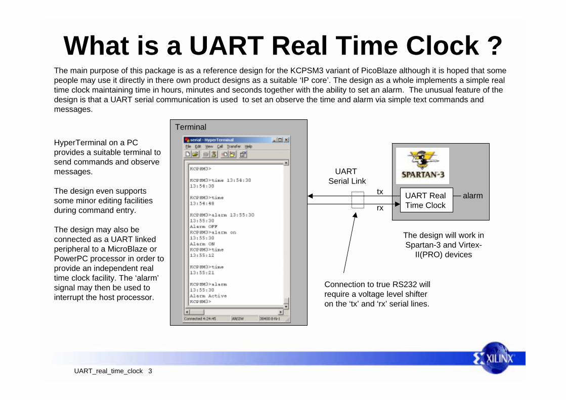
What is a UART Real Time Clock ?The main purpose of this package is as a reference design for the KCPSM3 variant of PicoBlaze although it is hoped that somepeople may use it directly in there own product designs as a suitable ‘IP core’. The design as a whole implements a simple realtime clock maintaining time in hours, minutes and seconds together with the ability to set an alarm. The unusual feature of thedesign is that a UART serial communication is used to set an observe the time and alarm via simple text commands andmessages.
UART Serial Link
UART RealTime Clock
Terminal
tx
rxalarm
HyperTerminal on a PCprovides a suitable terminal tosend commands and observemessages.
The design even supportssome minor editing facilitiesduring command entry.
The design may also beconnected as a UART linkedperipheral to a MicroBlaze orPowerPC processor in order toprovide an independent realtime clock facility. The ‘alarm’signal may then be used tointerrupt the host processor.
The design will work inSpartan-3 and Virtex-
II(PRO) devices
Connection to true RS232 willrequire a voltage level shifteron the ‘tx’ and ‘rx’ serial lines.
UART_real_time_clock 4
Reference DesignAs a reference design, the supplied VHDL and assembler code illustrates a design based on the KCPSM3 variant of PicoBlazeand demonstrates the following…...
• Connection of KCPSM3 to the Program ROM.• Connection of UART macros supplied with KCPSM3 - Input and output ports and baud rate timing.• Interrupt generation with a fixed interval timer and use of interrupt acknowledge signal.
Hardware VHDL design
Software KCPSM3 design
• Use of CONSTANT directives to define ports, bits within ports, scratch pad memory locations and useful values.• Interrupt Service Routine (ISR).• Use of scratch pad memory.• Communications with UART receiver and transmitter.• ASCII string handling.• Use of COMPARE and TEST instructions which are new with the KCPSM3 variant of PicoBlaze.
Useful PSM subroutines include….
• UART communications.• ASCII to decimal and decimal to ASCII conversions.• Lower case to upper case character conversion.• UART character string reading and editing.• Real time clock.• List of ASCII constants.
UART_real_time_clock 5
Understanding the DesignTo begin to use the design as a reference, it is useful to understand what it does and ideally to try it out with some suitablehardware and a PC. The design is supplied as just two files…..
The hardware definition is supplied in a VHDL file called ‘uart_clock.vhd. This will need to be added to a suitable project andeither used directly as the top level of your project or as a macro within a larger design. To complete the hardware definition youwill need to add all the VHDL files from the KCPSM3 (PicoBlaze) package, which also includes the UART macros.
The KCPSM3 software is provided as ‘uclock.psm’ which you will need to assemble using the KCPSM3 assembler.
Recommendation
Using the KCPSM3 documentation for guidance, ensure that you can assemble the supplied PSM program and synthesize thecomplete design into a Spartan3 or Virtex-II(PRO) device. These files are known to work and will help you to resolve any designflow issues.
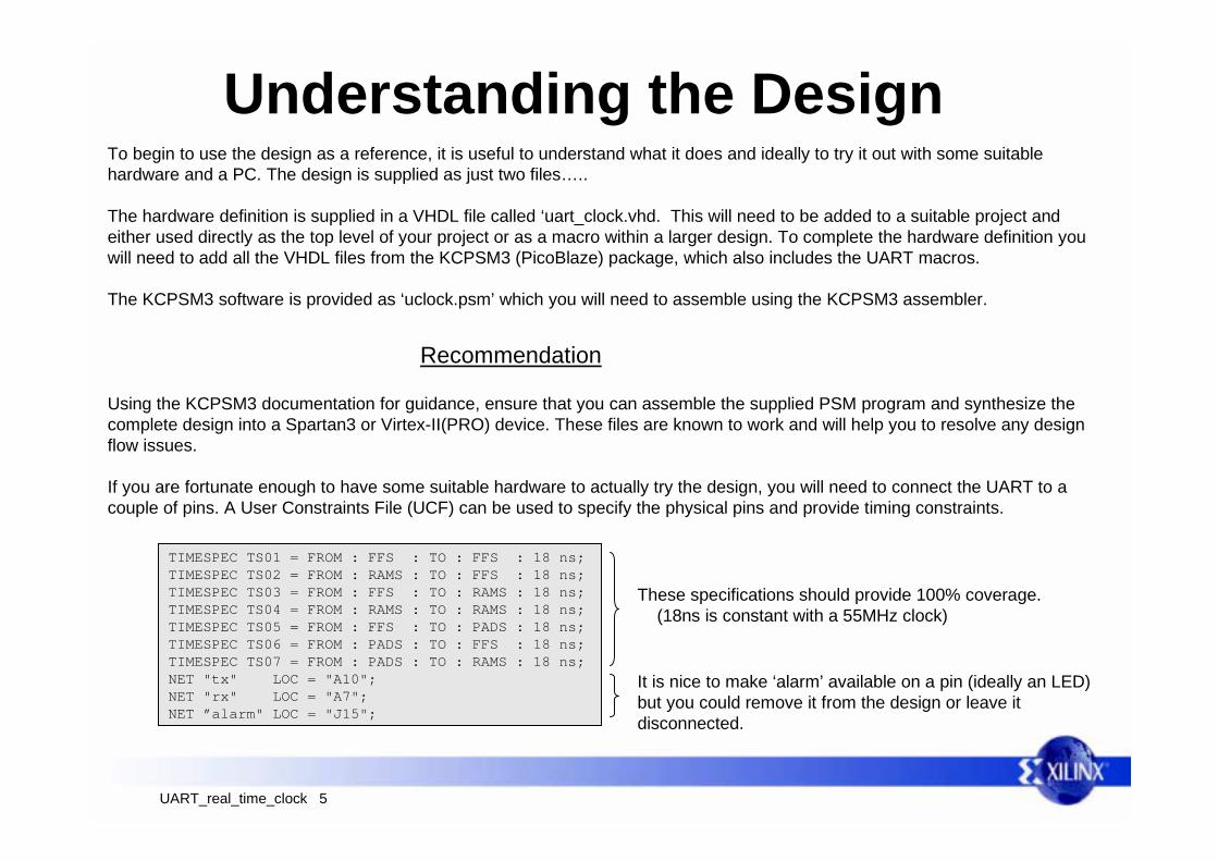
If you are fortunate enough to have some suitable hardware to actually try the design, you will need to connect the UART to acouple of pins. A User Constraints File (UCF) can be used to specify the physical pins and provide timing constraints.
TIMESPEC TS01 = FROM : FFS : TO : FFS : 18 ns;TIMESPEC TS02 = FROM : RAMS : TO : FFS : 18 ns;TIMESPEC TS03 = FROM : FFS : TO : RAMS : 18 ns;TIMESPEC TS04 = FROM : RAMS : TO : RAMS : 18 ns;TIMESPEC TS05 = FROM : FFS : TO : PADS : 18 ns; TIMESPEC TS06 = FROM : PADS : TO : FFS : 18 ns; TIMESPEC TS07 = FROM : PADS : TO : RAMS : 18 ns;NET "tx" LOC = "A10";NET "rx" LOC = "A7";NET ”alarm" LOC = "J15";
These specifications should provide 100% coverage. (18ns is constant with a 55MHz clock)
It is nice to make ‘alarm’ available on a pin (ideally an LED)but you could remove it from the design or leave itdisconnected.

UART_real_time_clock 6
HyperTerminal SetupHyperTerminal running on a PC can provide a very simple terminal for communication with ‘uart_clock’. Here are the requiredsettings for the design and how to configure HyperTerminal.
1 - Disconnect2 - Configure the communication link
2a - select serial port (typically COM1)
2b - Port Settings
8 bits
None
1 stopNone
38400
3 - Settings4 - Connect
3a - ASCII Setup
‘uart_clock’ will echo characters
‘uart_clock’ only transmits carriage return
UART_real_time_clock 7
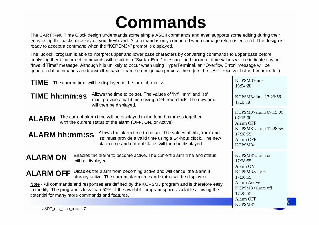
CommandsThe UART Real Time Clock design understands some simple ASCII commands and even supports some editing during theirentry using the backspace key on your keyboard. A command is only competed when carriage return is entered. The design isready to accept a command when the “KCPSM3>” prompt is displayed.
TIME The current time will be displayed in the form hh:mm:ss
TIME hh:mm:ss Allows the time to be set. The values of ‘hh’, ‘mm’ and ‘ss’must provide a valid time using a 24-hour clock. The new timewill then be displayed.
ALARM
ALARM hh:mm:ss
KCPSM3>time16:54:28
KCPSM3>time 17:23:5617:23:56
The current alarm time will be displayed in the form hh:mm:ss togetherwith the current status of the alarm (OFF, ON, or Active)
Allows the alarm time to be set. The values of ‘hh’, ‘mm’ and‘ss’ must provide a valid time using a 24-hour clock. The newalarm time and current status will then be displayed.
KCPSM3>alarm 07:15:0007:15:00Alarm OFFKCPSM3>alarm 17:28:5517:28:55Alarm OFFKCPSM3>
ALARM ON
ALARM OFF
Enables the alarm to become active. The current alarm time and statuswill be displayed
Disables the alarm from becoming active and will cancel the alarm ifalready active. The current alarm time and status will be displayed
KCPSM3>alarm on17:28:55Alarm ONKCPSM3>alarm17:28:55Alarm ActiveKCPSM3>alarm off17:28:55Alarm OFFKCPSM3>
Note - All commands and responses are defined by the KCPSM3 program and is therefore easyto modify. The program is less than 50% of the available program space available allowing thepotential for many more commands and features.
The ‘uclock’ program is able to interpret upper and lower case characters by converting commands to upper case beforeanalysing them. Incorrect commands will result in a “Syntax Error” message and incorrect time values will be indicated by an“Invalid Time” message. Although it is unlikely to occur when using HyperTerminal, an “Overflow Error” message will begenerated if commands are transmitted faster than the design can process them (i.e. the UART receiver buffer becomes full).

UART_real_time_clock 8
The Hardware - Program ROMThe connection of the program ROM is a straight forward. The KCPSM3 processor and the ‘uclock’ program are instantiated andsignals used to make direct connections. In this design the reset port is not required so it is tied to ground.
IN_PORT[7:0]
PORT_ID[7:0]INTERRUPT
INSTRUCTION[17:0]
OUT_PORT[7:0]
ADDRESS[9:0]CLK
READ_STROBE
WRITE_STROBE
kcpsm3.vhd
RESET
INTERRUPT_ACK
ADDRESS[9:0]
INSTRUCTION[17:0]
CLK
uclock.vhd
processor: kcpsm3 port map( address => address, instruction => instruction, port_id => port_id, write_strobe => write_strobe, out_port => out_port, read_strobe => read_strobe, in_port => in_port, interrupt => interrupt, interrupt_ack => interrupt_ack, reset => ‘0’, clk => clk); program_rom: uclock port map( address => address, instruction => instruction, clk => clk);
addr
ess
inst
ruct
ion
The complete reference design is connected to a single clock source ‘clk’. We will see this signal used in the more generic VHDLcode, but here it is again a direct connection to the instantiated components.
UART_real_time_clock 9
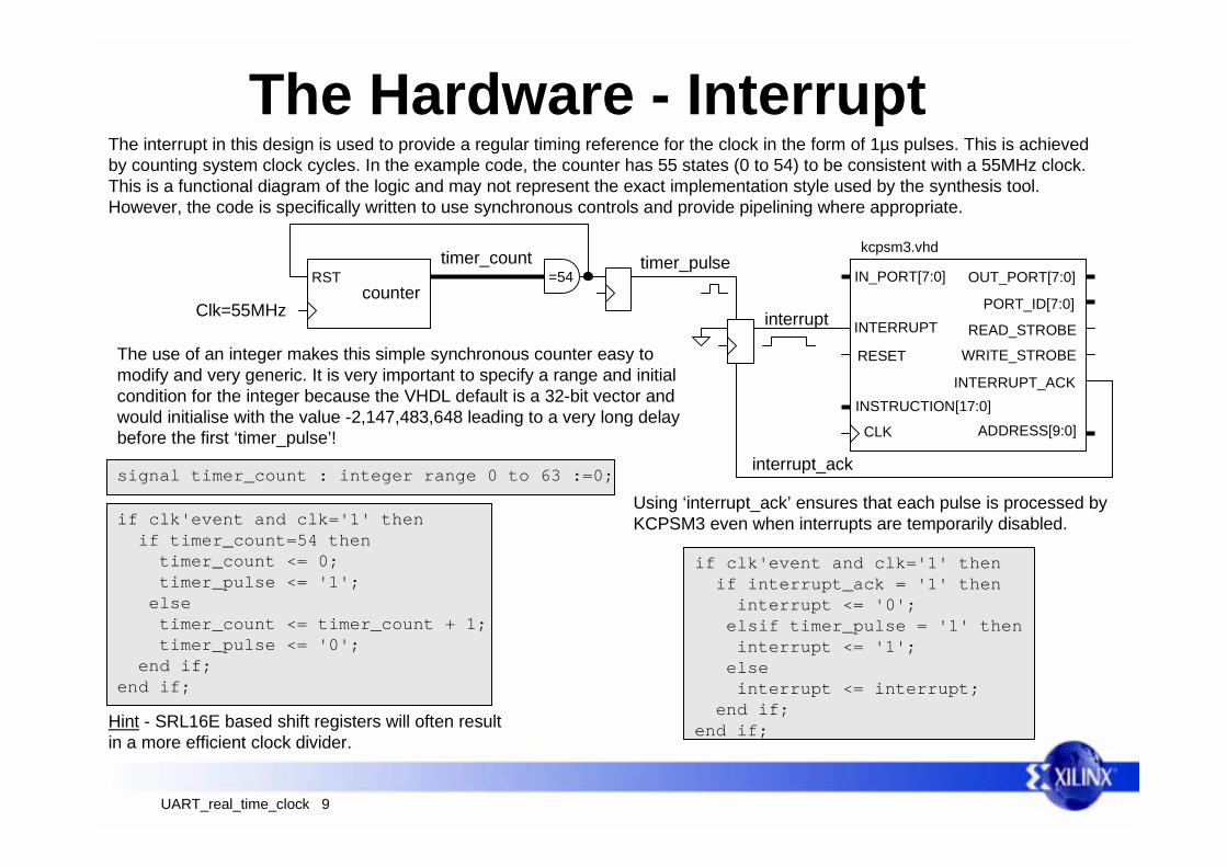
The Hardware - InterruptThe interrupt in this design is used to provide a regular timing reference for the clock in the form of 1µs pulses. This is achievedby counting system clock cycles. In the example code, the counter has 55 states (0 to 54) to be consistent with a 55MHz clock.This is a functional diagram of the logic and may not represent the exact implementation style used by the synthesis tool.However, the code is specifically written to use synchronous controls and provide pipelining where appropriate.
IN_PORT[7:0]
PORT_ID[7:0]INTERRUPT
INSTRUCTION[17:0]
OUT_PORT[7:0]
ADDRESS[9:0]CLK
READ_STROBE
WRITE_STROBE
kcpsm3.vhd
RESET
INTERRUPT_ACK
The use of an integer makes this simple synchronous counter easy tomodify and very generic. It is very important to specify a range and initialcondition for the integer because the VHDL default is a 32-bit vector andwould initialise with the value -2,147,483,648 leading to a very long delaybefore the first ‘timer_pulse’!
interrupt
interrupt_ack
timer_pulse
counter
timer_countRST =54
if clk'event and clk='1' then if timer_count=54 then timer_count <= 0; timer_pulse <= '1'; else timer_count <= timer_count + 1; timer_pulse <= '0'; end if;end if;
signal timer_count : integer range 0 to 63 :=0;
if clk'event and clk='1' then if interrupt_ack = '1' then interrupt <= '0'; elsif timer_pulse = '1' then interrupt <= '1'; else interrupt <= interrupt; end if;end if;
Clk=55MHz
Hint - SRL16E based shift registers will often resultin a more efficient clock divider.
Using ‘interrupt_ack’ ensures that each pulse is processed byKCPSM3 even when interrupts are temporarily disabled.
UART_real_time_clock 10
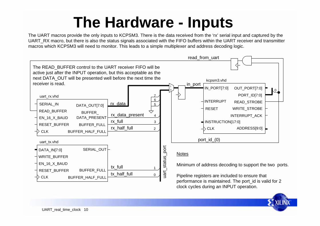
The Hardware - InputsThe UART macros provide the only inputs to KCPSM3. There is the data received from the ‘rx’ serial input and captured by theUART_RX macro, but there is also the status signals associated with the FIFO buffers within the UART receiver and transmittermacros which KCPSM3 will need to monitor. This leads to a simple multiplexer and address decoding logic.
DATA_IN[7:0]
WRITE_BUFFER
RESET_BUFFER
CLK
EN_16_X_BAUD
SERIAL_OUT
BUFFER_HALF_FULL
BUFFER_FULL
uart_tx.vhd
SERIAL_IN
READ_BUFFER
uart_rx.vhd
DATA_PRESENT
DATA_OUT[7:0]
EN_16_X_BAUD
BUFFER_HALF_FULL
BUFFER_FULLRESET_BUFFER
CLK
tx_half_full 0
tx_full 1
rx_half_full 2
rx_full 3
rx_data_present 4
IN_PORT[7:0]
PORT_ID[7:0]INTERRUPT
INSTRUCTION[17:0]
OUT_PORT[7:0]
ADDRESS[9:0]CLK
READ_STROBE
WRITE_STROBE
kcpsm3.vhd
RESET
INTERRUPT_ACK
567
uart_
stat
us_p
ort
rx_data
in_port01
BUFFER_
port_id_(0)
read_from_uart
0
Notes
Minimum of address decoding to support the two ports.
Pipeline registers are included to ensure thatperformance is maintained. The port_id is valid for 2clock cycles during an INPUT operation.
The READ_BUFFER control to the UART receiver FIFO will beactive just after the INPUT operation, but this acceptable as thenext DATA_OUT will be presented well before the next time thereceiver is read.
UART_real_time_clock 11
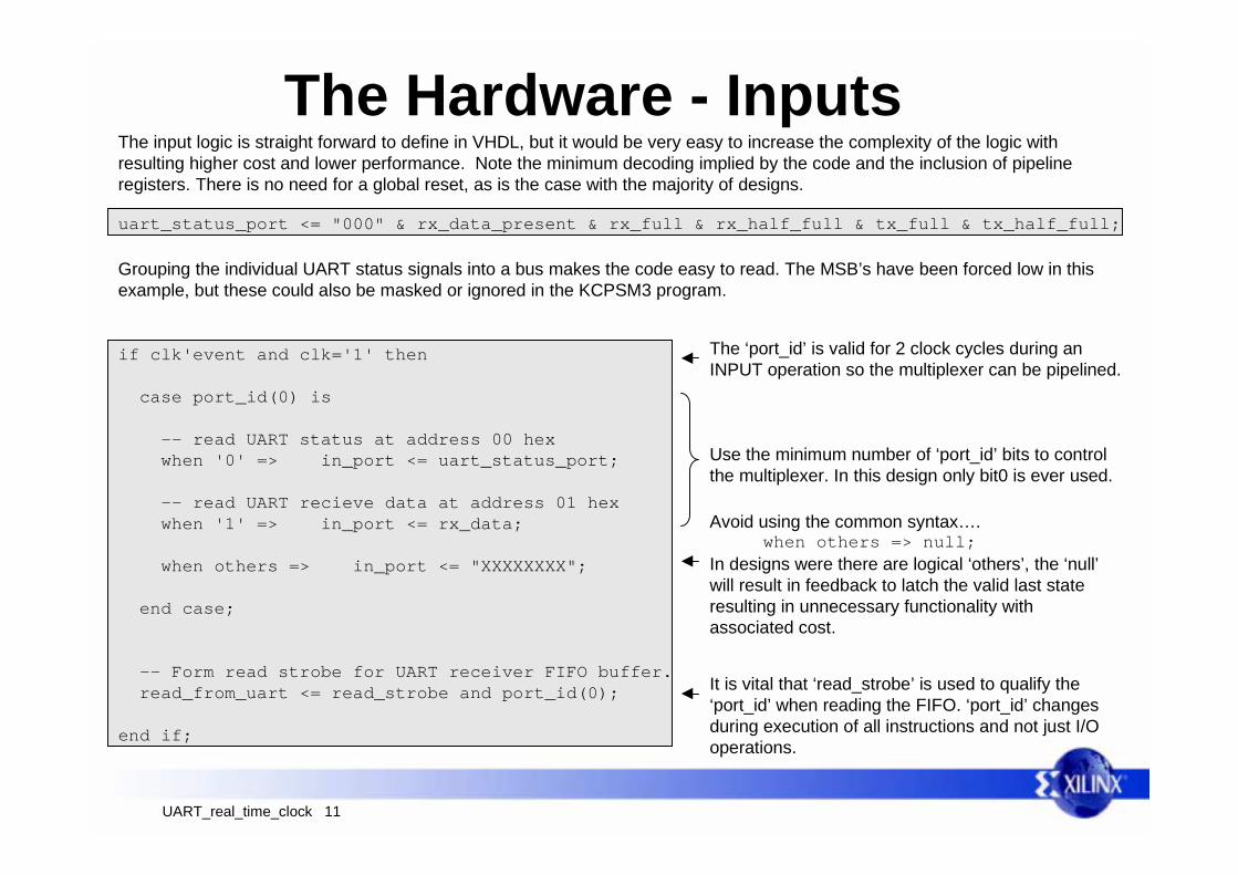
The Hardware - InputsThe input logic is straight forward to define in VHDL, but it would be very easy to increase the complexity of the logic withresulting higher cost and lower performance. Note the minimum decoding implied by the code and the inclusion of pipelineregisters. There is no need for a global reset, as is the case with the majority of designs.
if clk'event and clk='1' then
case port_id(0) is -- read UART status at address 00 hex when '0' => in_port <= uart_status_port;
-- read UART recieve data at address 01 hex when '1' => in_port <= rx_data; when others => in_port <= "XXXXXXXX";
end case;
-- Form read strobe for UART receiver FIFO buffer. read_from_uart <= read_strobe and port_id(0);
end if;
uart_status_port <= "000" & rx_data_present & rx_full & rx_half_full & tx_full & tx_half_full;
Grouping the individual UART status signals into a bus makes the code easy to read. The MSB’s have been forced low in thisexample, but these could also be masked or ignored in the KCPSM3 program.
The ‘port_id’ is valid for 2 clock cycles during anINPUT operation so the multiplexer can be pipelined.
Use the minimum number of ‘port_id’ bits to controlthe multiplexer. In this design only bit0 is ever used.
Avoid using the common syntax…. when others => null;In designs were there are logical ‘others’, the ‘null’will result in feedback to latch the valid last stateresulting in unnecessary functionality withassociated cost.
It is vital that ‘read_strobe’ is used to qualify the‘port_id’ when reading the FIFO. ‘port_id’ changesduring execution of all instructions and not just I/Ooperations.
UART_real_time_clock 12
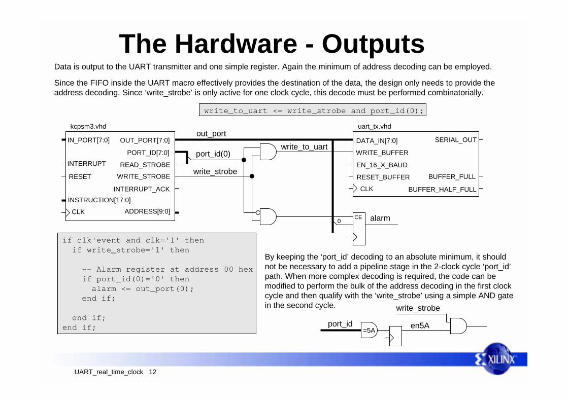
The Hardware - OutputsData is output to the UART transmitter and one simple register. Again the minimum of address decoding can be employed.
DATA_IN[7:0]
WRITE_BUFFER
RESET_BUFFER
CLK
EN_16_X_BAUD
SERIAL_OUT
BUFFER_HALF_FULL
BUFFER_FULL
uart_tx.vhd
write_to_uartout_port
IN_PORT[7:0]
PORT_ID[7:0]INTERRUPT
INSTRUCTION[17:0]
OUT_PORT[7:0]
ADDRESS[9:0]CLK
READ_STROBE
WRITE_STROBE
kcpsm3.vhd
RESET
INTERRUPT_ACK
alarm
port_id(0)
CE
write_strobe
0
write_to_uart <= write_strobe and port_id(0);
Since the FIFO inside the UART macro effectively provides the destination of the data, the design only needs to provide theaddress decoding. Since ‘write_strobe’ is only active for one clock cycle, this decode must be performed combinatorially.
if clk'event and clk='1' then if write_strobe='1' then
-- Alarm register at address 00 hex if port_id(0)='0' then alarm <= out_port(0); end if;
end if;end if;
By keeping the ‘port_id’ decoding to an absolute minimum, it shouldnot be necessary to add a pipeline stage in the 2-clock cycle ‘port_id’path. When more complex decoding is required, the code can bemodified to perform the bulk of the address decoding in the first clockcycle and then qualify with the ‘write_strobe’ using a simple AND gatein the second cycle.
port_id=5A
write_strobe
en5A
UART_real_time_clock 13
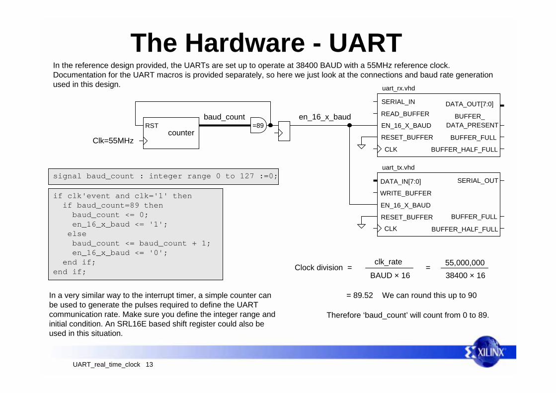
The Hardware - UARTIn the reference design provided, the UARTs are set up to operate at 38400 BAUD with a 55MHz reference clock.Documentation for the UART macros is provided separately, so here we just look at the connections and baud rate generationused in this design.
DATA_IN[7:0]
WRITE_BUFFER
RESET_BUFFER
CLK
EN_16_X_BAUD
SERIAL_OUT
BUFFER_HALF_FULL
BUFFER_FULL
uart_tx.vhd
SERIAL_IN
READ_BUFFER
uart_rx.vhd
DATA_PRESENT
DATA_OUT[7:0]
EN_16_X_BAUD
BUFFER_HALF_FULL
BUFFER_FULLRESET_BUFFER
CLK
BUFFER_
counter
baud_countRST =89
Clk=55MHz
if clk'event and clk='1' then if baud_count=89 then baud_count <= 0; en_16_x_baud <= '1'; else baud_count <= baud_count + 1; en_16_x_baud <= '0'; end if;end if;
signal baud_count : integer range 0 to 127 :=0;
en_16_x_baud
In a very similar way to the interrupt timer, a simple counter canbe used to generate the pulses required to define the UARTcommunication rate. Make sure you define the integer range andinitial condition. An SRL16E based shift register could also beused in this situation.
Clock division = clk_rate
BAUD × 16= 55,000,000
38400 × 16
= 89.52 We can round this up to 90
Therefore ‘baud_count’ will count from 0 to 89.

UART_real_time_clock 14
KCPSM3 Program CodeAs a reference design, this document is not intended to teach how to write software or explain how the individual instructions forKCPSM3 operate. Coding styles are very much a personal choice, but it is always useful to know what is possible and toconsider some useful techniques which enable code to be easier to write, manage and understand.
In the following pages, excerpts of the supplied ‘uclock.psm’ program are selected to highlight particular coding styles andillustrate how the features and instruction set of KCPSM3 can be used. There will be cases where more efficient code could bewritten and there will be cases where more readable code could be written, but it is hoped that even in the form supplied it willinspire you with some ideas of your own.
Finally, the program has been written using multiple sub routines. Since some of these provide useful functions such ascommunications with the UART macros, these may also be directly useful in other designs.
Hint - It will be useful to have a copy of the KCPSM3 documentation when reviewing the code.
Assemble the ‘uclock.psm’ program and become familiar with the files which KCPSM3 generates.Take a look at the ‘uclock.log’ file…....
How much of the available program memory has been used?Where is the interrupt service routine (ISR) located?Four registers have been given special names. What are they?
Take a look at the ‘constant.txt’ file…....Observe the relatively long list of constants that were declared.Notice how many have the same value.How many minutes are there in an hour (in hexadecimal)?
Before you continue…..
Register Names
sCsDsEsF
UART_real_time_clock 15
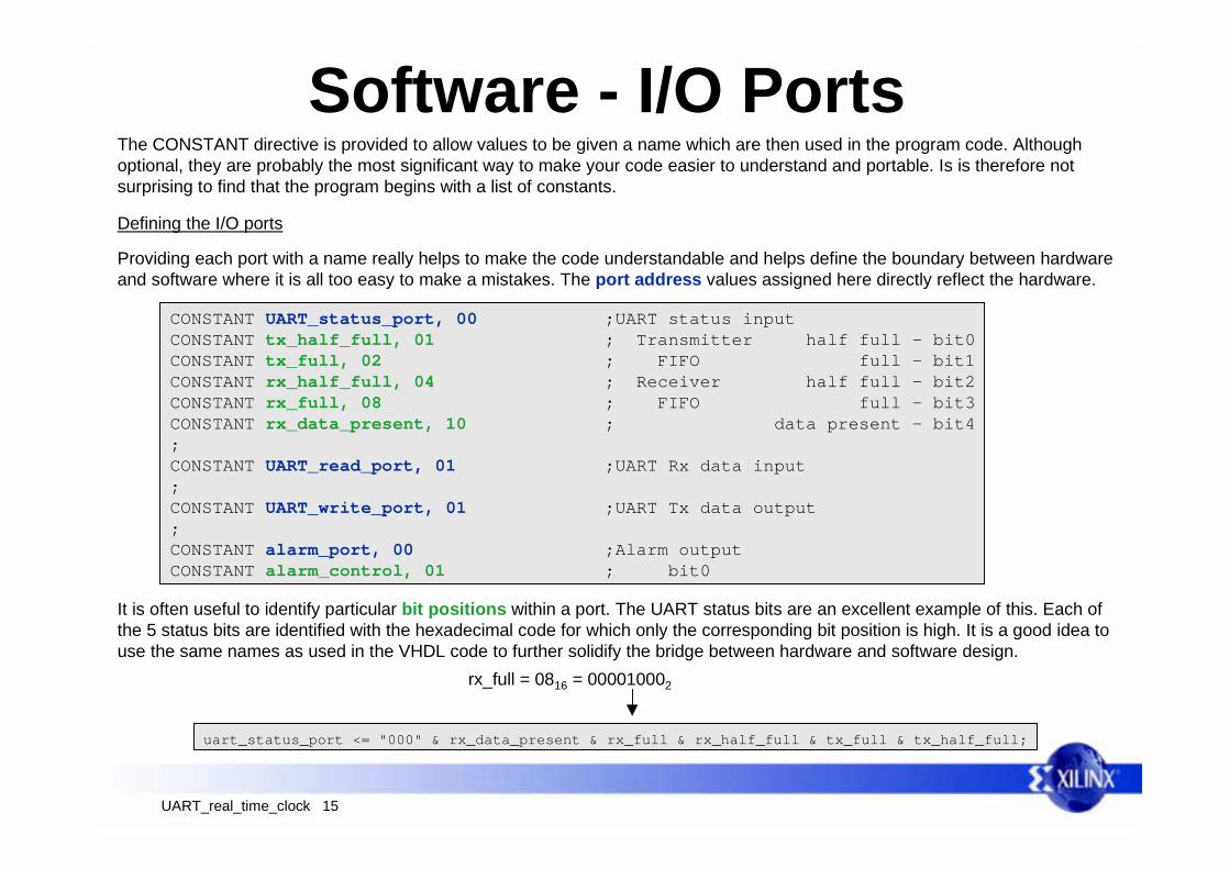
Software - I/O PortsThe CONSTANT directive is provided to allow values to be given a name which are then used in the program code. Althoughoptional, they are probably the most significant way to make your code easier to understand and portable. Is is therefore notsurprising to find that the program begins with a list of constants.
CONSTANT UART_status_port, 00 ;UART status inputCONSTANT tx_half_full, 01 ; Transmitter half full - bit0CONSTANT tx_full, 02 ; FIFO full - bit1CONSTANT rx_half_full, 04 ; Receiver half full - bit2CONSTANT rx_full, 08 ; FIFO full - bit3CONSTANT rx_data_present, 10 ; data present - bit4;CONSTANT UART_read_port, 01 ;UART Rx data input;CONSTANT UART_write_port, 01 ;UART Tx data output;CONSTANT alarm_port, 00 ;Alarm outputCONSTANT alarm_control, 01 ; bit0
Providing each port with a name really helps to make the code understandable and helps define the boundary between hardwareand software where it is all too easy to make a mistakes. The port address values assigned here directly reflect the hardware.
It is often useful to identify particular bit positions within a port. The UART status bits are an excellent example of this. Each ofthe 5 status bits are identified with the hexadecimal code for which only the corresponding bit position is high. It is a good idea touse the same names as used in the VHDL code to further solidify the bridge between hardware and software design.
rx_full = 0816 = 000010002
uart_status_port <= "000" & rx_data_present & rx_full & rx_half_full & tx_full & tx_half_full;
Defining the I/O ports

UART_real_time_clock 16
Software - Scratch Pad MemoryIt useful to have a picture of how the scratch pad memory will be used. This ‘memory map’ will help you allocate locations and bea useful reference to the names you have allocated as you write your code. Below is the map for the ‘uclock’ program. At the endof this document you will find a set of clean resource charts for you to help with development of your own programs.
;Scratch Pad Memory Locations;CONSTANT us_time_stamp_lsb, 00 ;16-bit micro-second timestampCONSTANT us_time_stamp_msb, 01
Constant values are now used to define the address within scratch pad memory at which a value is stored or at which the start ofa block of data will be stored. Again, constants can be used to identify the special meaning of bits at some locations.
Defining the Scratch Pad Memory Locations
Scratch Pad Memory000102030405060708090A0B0C0D0E0F
101112131415161718191A1B1C1D1E1F
202122232425262728292A2B2C2D2E2F
303132333435363738393A3B3C3D3E3F
us_time_stamp_lsbus_time_stamp_msb
us_time_msbus_time_lsb
ms_time_msbms_time_lsb
real_time_hoursreal_time_minutesreal_time_secondsalarm_time_hoursalarm_time_minutesalarm_time_seconds
time_preserve0time_preserve1time_preserve2time_preserve3time_preserve4time_preserve5
string_start
alarm_status
tem
pora
ryst
orag
e
Text
stri
ng s
tora
ge(e
nds
with
car
riage
retu
rn)
time
alarm
millimicro

UART_real_time_clock 17
Software - ConstantsThe final use of the CONSTANT directive is to define actual constant values which will be used to make the code easier to readand write. Note that these constants do not really need to be located at the beginning of the program. If they are significant to agiven sub routine, then this is a good place to put them and will make the code more portable.
;Useful constants for real time clock operations;CONSTANT count_1000_lsb, E8 ;lower 8-bits of 1000 count valueCONSTANT count_1000_msb, 03 ;upper 8-bits of 1000 count valueCONSTANT hours_in_a_day, 18 ;24 hours in a dayCONSTANT minutes_in_an_hour, 3C ;60 minutes in an hourCONSTANT seconds_in_a_minute, 3C ;60 seconds in a minute
Constants are used to define useful values where they are needed in the program. They are particularly good at helping todocument the code automatically especially as the KCPSM3 assembler only directly supports hexadecimal values.
Note - The KCPSM3 assembler currently supports a maximum of 300 constants within a program, but this really should beadequate for any program. ‘uclock.psm’ defines just over 100 constants including the table of ASCII characters.
Defining useful values
100010 = 03E816
;ASCII table;CONSTANT character_a, 61CONSTANT character_b, 62CONSTANT character_c, 63CONSTANT character_d, 64
Constant values are applied globally to the program regardless of where they are defined. Therefore the very end of the programis a good place to define useful constant values even if they are not all required by the program.
The end of ‘uclock.psm’ defines many of the characters in the ASCII table. Thesemake it easier to define and interpret text messages. It is unlikely that everycharacter is used in the program (and it isn’t) but the complete definition is usefulto copy to other programs and makes modifications to the program simple.
UART_real_time_clock 18
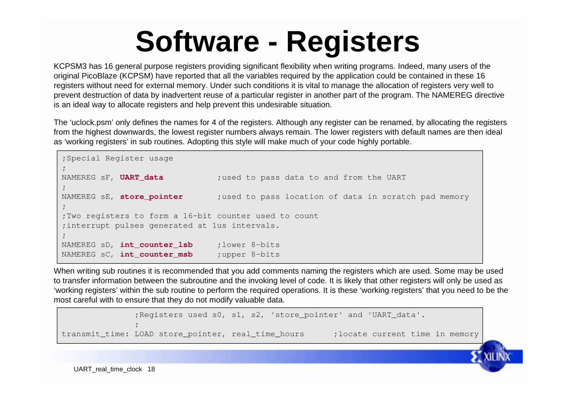
Software - RegistersKCPSM3 has 16 general purpose registers providing significant flexibility when writing programs. Indeed, many users of theoriginal PicoBlaze (KCPSM) have reported that all the variables required by the application could be contained in these 16registers without need for external memory. Under such conditions it is vital to manage the allocation of registers very well toprevent destruction of data by inadvertent reuse of a particular register in another part of the program. The NAMEREG directiveis an ideal way to allocate registers and help prevent this undesirable situation.
;Special Register usage;NAMEREG sF, UART_data ;used to pass data to and from the UART;NAMEREG sE, store_pointer ;used to pass location of data in scratch pad memory;;Two registers to form a 16-bit counter used to count;interrupt pulses generated at 1us intervals.;NAMEREG sD, int_counter_lsb ;lower 8-bitsNAMEREG sC, int_counter_msb ;upper 8-bits
When writing sub routines it is recommended that you add comments naming the registers which are used. Some may be usedto transfer information between the subroutine and the invoking level of code. It is likely that other registers will only be used as‘working registers’ within the sub routine to perform the required operations. It is these ‘working registers’ that you need to be themost careful with to ensure that they do not modify valuable data.
The ‘uclock.psm’ only defines the names for 4 of the registers. Although any register can be renamed, by allocating the registersfrom the highest downwards, the lowest register numbers always remain. The lower registers with default names are then idealas ‘working registers’ in sub routines. Adopting this style will make much of your code highly portable.
;Registers used s0, s1, s2, 'store_pointer' and 'UART_data'. ;transmit_time: LOAD store_pointer, real_time_hours ;locate current time in memory
UART_real_time_clock 19
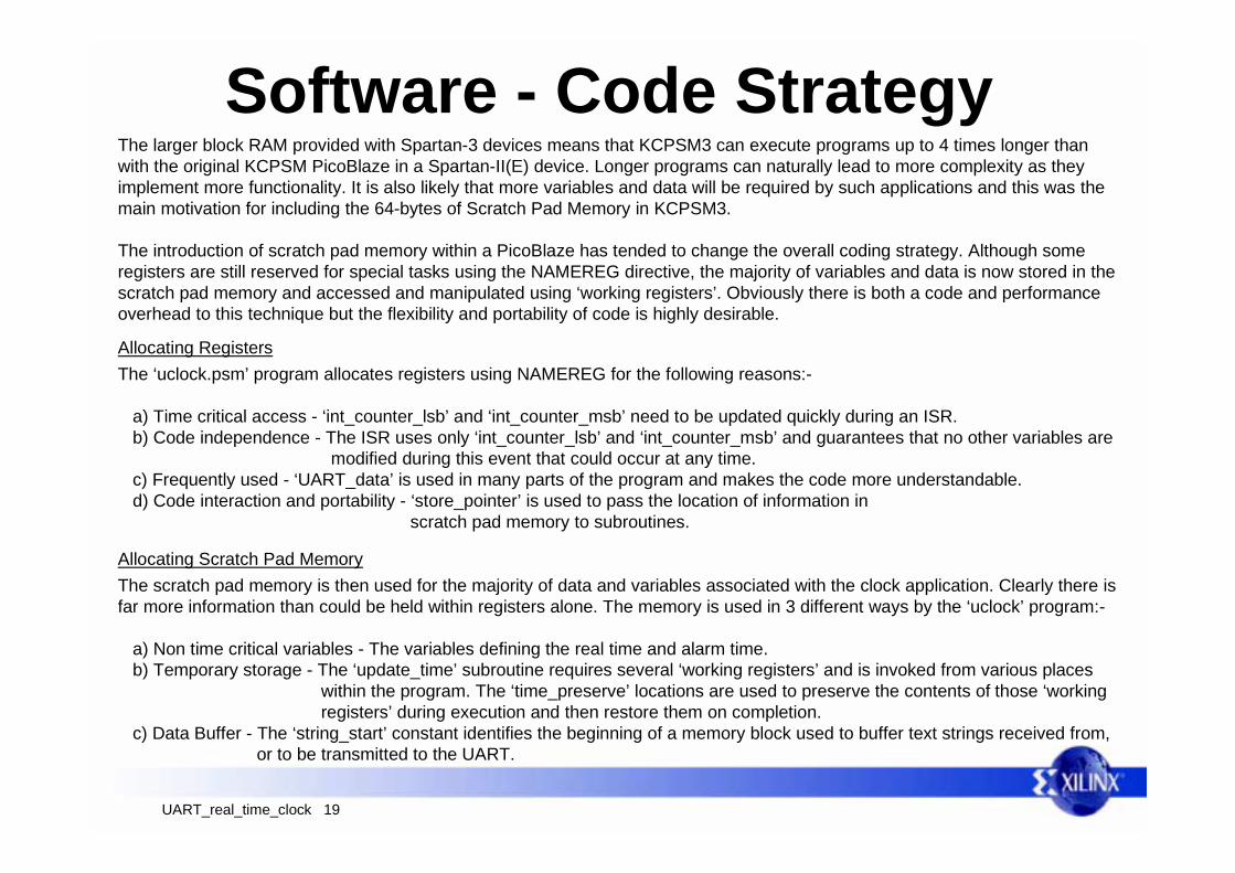
Software - Code StrategyThe larger block RAM provided with Spartan-3 devices means that KCPSM3 can execute programs up to 4 times longer thanwith the original KCPSM PicoBlaze in a Spartan-II(E) device. Longer programs can naturally lead to more complexity as theyimplement more functionality. It is also likely that more variables and data will be required by such applications and this was themain motivation for including the 64-bytes of Scratch Pad Memory in KCPSM3.
The introduction of scratch pad memory within a PicoBlaze has tended to change the overall coding strategy. Although someregisters are still reserved for special tasks using the NAMEREG directive, the majority of variables and data is now stored in thescratch pad memory and accessed and manipulated using ‘working registers’. Obviously there is both a code and performanceoverhead to this technique but the flexibility and portability of code is highly desirable.
The ‘uclock.psm’ program allocates registers using NAMEREG for the following reasons:-
a) Time critical access - ‘int_counter_lsb’ and ‘int_counter_msb’ need to be updated quickly during an ISR. b) Code independence - The ISR uses only ‘int_counter_lsb’ and ‘int_counter_msb’ and guarantees that no other variables are modified during this event that could occur at any time. c) Frequently used - ‘UART_data’ is used in many parts of the program and makes the code more understandable. d) Code interaction and portability - ‘store_pointer’ is used to pass the location of information in scratch pad memory to subroutines.
Allocating Registers
Allocating Scratch Pad MemoryThe scratch pad memory is then used for the majority of data and variables associated with the clock application. Clearly there isfar more information than could be held within registers alone. The memory is used in 3 different ways by the ‘uclock’ program:-
a) Non time critical variables - The variables defining the real time and alarm time. b) Temporary storage - The ‘update_time’ subroutine requires several ‘working registers’ and is invoked from various places within the program. The ‘time_preserve’ locations are used to preserve the contents of those ‘working registers’ during execution and then restore them on completion. c) Data Buffer - The ‘string_start’ constant identifies the beginning of a memory block used to buffer text strings received from, or to be transmitted to the UART.
UART_real_time_clock 20
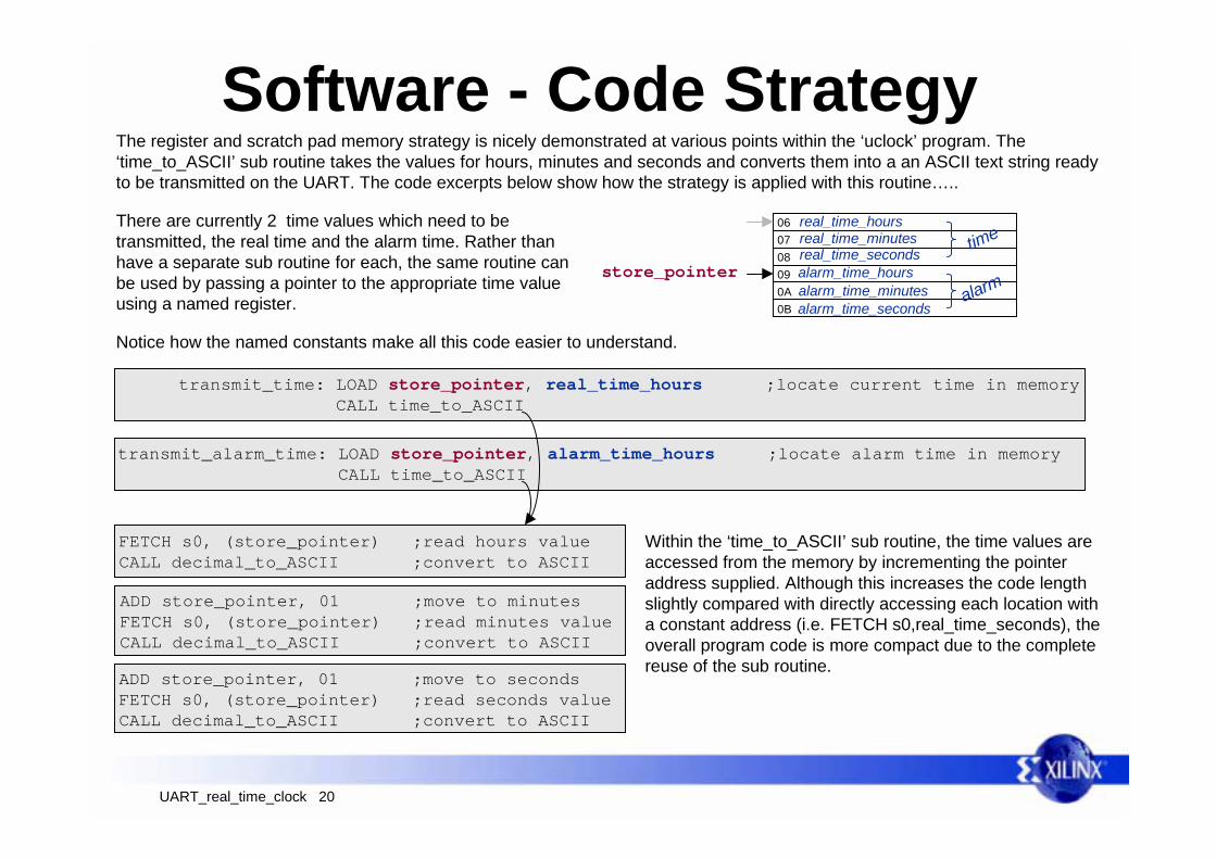
Software - Code StrategyThe register and scratch pad memory strategy is nicely demonstrated at various points within the ‘uclock’ program. The‘time_to_ASCII’ sub routine takes the values for hours, minutes and seconds and converts them into a an ASCII text string readyto be transmitted on the UART. The code excerpts below show how the strategy is applied with this routine…..
There are currently 2 time values which need to betransmitted, the real time and the alarm time. Rather thanhave a separate sub routine for each, the same routine canbe used by passing a pointer to the appropriate time valueusing a named register.
transmit_time: LOAD store_pointer, real_time_hours ;locate current time in memory CALL time_to_ASCII
transmit_alarm_time: LOAD store_pointer, alarm_time_hours ;locate alarm time in memory CALL time_to_ASCII
060708090A0B
real_time_minutesreal_time_secondsalarm_time_hoursalarm_time_minutesalarm_time_seconds
time
alarm
real_time_hours
store_pointer
FETCH s0, (store_pointer) ;read hours valueCALL decimal_to_ASCII ;convert to ASCII
ADD store_pointer, 01 ;move to minutesFETCH s0, (store_pointer) ;read minutes valueCALL decimal_to_ASCII ;convert to ASCII
ADD store_pointer, 01 ;move to secondsFETCH s0, (store_pointer) ;read seconds valueCALL decimal_to_ASCII ;convert to ASCII
Within the ‘time_to_ASCII’ sub routine, the time values areaccessed from the memory by incrementing the pointeraddress supplied. Although this increases the code lengthslightly compared with directly accessing each location witha constant address (i.e. FETCH s0,real_time_seconds), theoverall program code is more compact due to the completereuse of the sub routine.
Notice how the named constants make all this code easier to understand.
UART_real_time_clock 21
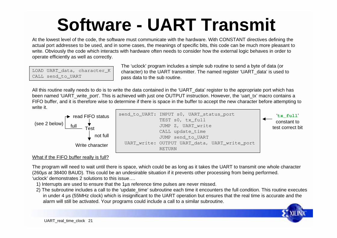
Software - UART TransmitAt the lowest level of the code, the software must communicate with the hardware. With CONSTANT directives defining theactual port addresses to be used, and in some cases, the meanings of specific bits, this code can be much more pleasant towrite. Obviously the code which interacts with hardware often needs to consider how the external logic behaves in order tooperate efficiently as well as correctly.
LOAD UART_data, character_KCALL send_to_UART
send_to_UART: INPUT s0, UART_status_port TEST s0, tx_full JUMP Z, UART_write CALL update_time JUMP send_to_UART UART_write: OUTPUT UART_data, UART_write_port RETURN
The ‘uclock’ program includes a simple sub routine to send a byte of data (orcharacter) to the UART transmitter. The named register ‘UART_data’ is used topass data to the sub routine.
All this routine really needs to do is to write the data contained in the ‘UART_data’ register to the appropriate port which hasbeen named ‘UART_write_port’. This is achieved with just one OUTPUT instruction. However, the ‘uart_tx’ macro contains aFIFO buffer, and it is therefore wise to determine if there is space in the buffer to accept the new character before attempting towrite it.
read FIFO status
Testfull
not full
Write character
‘tx_full’constant to
test correct bit
The program will need to wait until there is space, which could be as long as it takes the UART to transmit one whole character(260µs at 38400 BAUD). This could be an undesirable situation if it prevents other processing from being performed.‘uclock’ demonstrates 2 solutions to this issue…. 1) Interrupts are used to ensure that the 1µs reference time pulses are never missed. 2) The subroutine includes a call to the ‘update_time’ subroutine each time it encounters the full condition. This routine executes in under 4 µs (55MHz clock) which is insignificant to the UART operation but ensures that the real time is accurate and the alarm will still be activated. Your programs could include a call to a similar subroutine.
(see 2 below)
What if the FIFO buffer really is full?
UART_real_time_clock 22
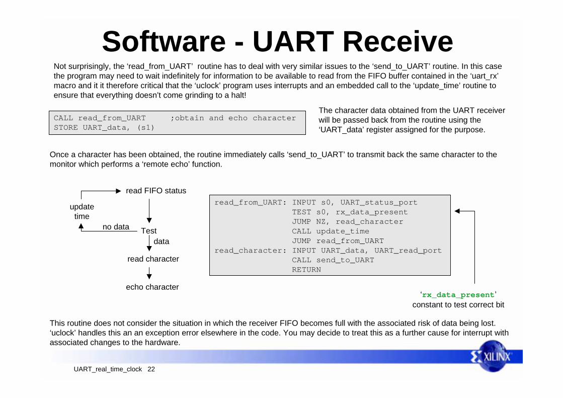
Software - UART ReceiveNot surprisingly, the ‘read_from_UART’ routine has to deal with very similar issues to the ‘send_to_UART’ routine. In this casethe program may need to wait indefinitely for information to be available to read from the FIFO buffer contained in the ‘uart_rx’macro and it it therefore critical that the ‘uclock’ program uses interrupts and an embedded call to the ‘update_time’ routine toensure that everything doesn’t come grinding to a halt!
CALL read_from_UART ;obtain and echo characterSTORE UART_data, (s1)
read_from_UART: INPUT s0, UART_status_port TEST s0, rx_data_present JUMP NZ, read_character CALL update_time JUMP read_from_UARTread_character: INPUT UART_data, UART_read_port CALL send_to_UART RETURN
The character data obtained from the UART receiverwill be passed back from the routine using the‘UART_data’ register assigned for the purpose.
Once a character has been obtained, the routine immediately calls ‘send_to_UART’ to transmit back the same character to themonitor which performs a ‘remote echo’ function.
read FIFO status
Test no data
data
read character
‘rx_data_present’constant to test correct bit
echo character
updatetime
This routine does not consider the situation in which the receiver FIFO becomes full with the associated risk of data being lost.‘uclock’ handles this an an exception error elsewhere in the code. You may decide to treat this as a further cause for interrupt withassociated changes to the hardware.
UART_real_time_clock 23
Software - Interrupt
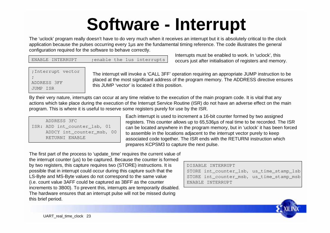
By their very nature, interrupts can occur at any time relative to the execution of the main program code. It is vital that anyactions which take place during the execution of the Interrupt Service Routine (ISR) do not have an adverse effect on the mainprogram. This is where it is useful to reserve some registers purely for use by the ISR.
ENABLE INTERRUPT ;enable the 1us interrupts
ADDRESS 3FCISR: ADD int_counter_lsb, 01 ADDCY int_counter_msb, 00 RETURNI ENABLE
The interrupt will invoke a ‘CALL 3FF’ operation requiring an appropriate JUMP instruction to beplaced at the most significant address of the program memory. The ADDRESS directive ensuresthis JUMP ‘vector’ is located it this position.
The first part of the process to ‘update_time’ requires the current value ofthe interrupt counter (µs) to be captured. Because the counter is formedby two registers, this capture requires two (STORE) instructions. It ispossible that in interrupt could occur during this capture such that theLS-Byte and MS-Byte values do not correspond to the same value(i.e. count value 3AFF could be captured as 3BFF as the counterincrements to 3B00). To prevent this, interrupts are temporarily disabled.The hardware ensures that an interrupt pulse will not be missed duringthis brief period.
;Interrupt vector;ADDRESS 3FFJUMP ISR
The ‘uclock’ program really doesn’t have to do very much when it receives an interrupt but it is absolutely critical to the clockapplication because the pulses occurring every 1µs are the fundamental timing reference. The code illustrates the generalconfiguration required for the software to behave correctly.
Interrupts must be enabled to work. In ‘uclock’, thisoccurs just after initialisation of registers and memory.
Each interrupt is used to increment a 16-bit counter formed by two assignedregisters. This counter allows up to 65,536µs of real time to be recorded. The ISRcan be located anywhere in the program memory, but in ‘uclock’ it has been forcedto assemble in the locations adjacent to the interrupt vector purely to keepassociated code together. The ISR ends with the RETURNI instruction whichprepares KCPSM3 to capture the next pulse.
DISABLE INTERRUPTSTORE int_counter_lsb, us_time_stamp_lsbSTORE int_counter_msb, us_time_stamp_msbENABLE INTERRUPT
UART_real_time_clock 24
Software - ASCII codes
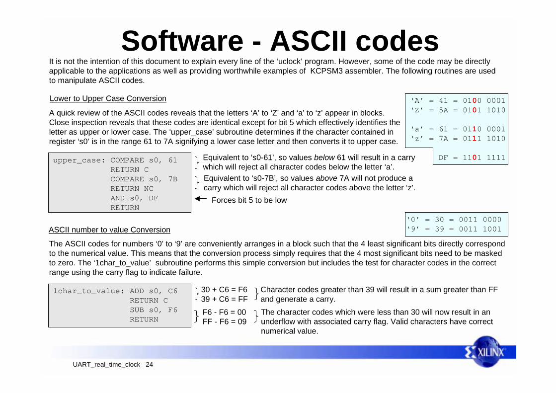
upper_case: COMPARE s0, 61 RETURN C COMPARE s0, 7B RETURN NC AND s0, DF RETURN
It is not the intention of this document to explain every line of the ‘uclock’ program. However, some of the code may be directlyapplicable to the applications as well as providing worthwhile examples of KCPSM3 assembler. The following routines are usedto manipulate ASCII codes.
‘A’ = 41 = 0100 0001‘Z’ = 5A = 0101 1010
‘a’ = 61 = 0110 0001‘z’ = 7A = 0111 1010
DF = 1101 1111
Lower to Upper Case Conversion
A quick review of the ASCII codes reveals that the letters ‘A’ to ‘Z’ and ‘a’ to ‘z’ appear in blocks.Close inspection reveals that these codes are identical except for bit 5 which effectively identifies theletter as upper or lower case. The ‘upper_case’ subroutine determines if the character contained inregister ‘s0’ is in the range 61 to 7A signifying a lower case letter and then converts it to upper case.
Equivalent to ‘s0-61’, so values below 61 will result in a carrywhich will reject all character codes below the letter ‘a’.Equivalent to ‘s0-7B’, so values above 7A will not produce acarry which will reject all character codes above the letter ‘z’.
Forces bit 5 to be low
1char_to_value: ADD s0, C6 RETURN C SUB s0, F6 RETURN
ASCII number to value Conversion‘0’ = 30 = 0011 0000‘9’ = 39 = 0011 1001
The ASCII codes for numbers ‘0’ to ‘9’ are conveniently arranges in a block such that the 4 least significant bits directly correspondto the numerical value. This means that the conversion process simply requires that the 4 most significant bits need to be maskedto zero. The ‘1char_to_value’ subroutine performs this simple conversion but includes the test for character codes in the correctrange using the carry flag to indicate failure.
30 + C6 = F639 + C6 = FF
Character codes greater than 39 will result in a sum greater than FFand generate a carry.
F6 - F6 = 00FF - F6 = 09
The character codes which were less than 30 will now result in anunderflow with associated carry flag. Valid characters have correctnumerical value.
UART_real_time_clock 25
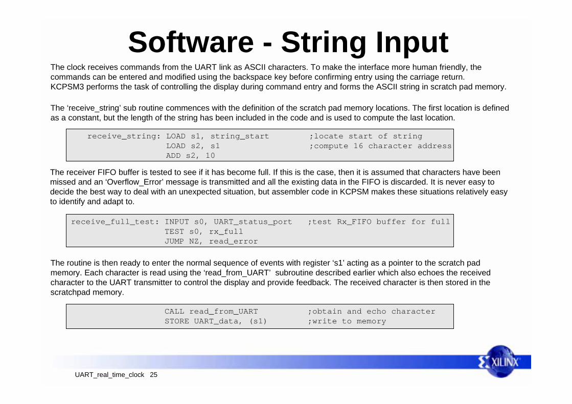
Software - String InputThe clock receives commands from the UART link as ASCII characters. To make the interface more human friendly, thecommands can be entered and modified using the backspace key before confirming entry using the carriage return.KCPSM3 performs the task of controlling the display during command entry and forms the ASCII string in scratch pad memory.
The ‘receive_string’ sub routine commences with the definition of the scratch pad memory locations. The first location is definedas a constant, but the length of the string has been included in the code and is used to compute the last location.
receive_string: LOAD s1, string_start ;locate start of string LOAD s2, s1 ;compute 16 character address ADD s2, 10
receive_full_test: INPUT s0, UART_status_port ;test Rx_FIFO buffer for full TEST s0, rx_full JUMP NZ, read_error
The receiver FIFO buffer is tested to see if it has become full. If this is the case, then it is assumed that characters have beenmissed and an ‘Overflow_Error’ message is transmitted and all the existing data in the FIFO is discarded. It is never easy todecide the best way to deal with an unexpected situation, but assembler code in KCPSM makes these situations relatively easyto identify and adapt to.
The routine is then ready to enter the normal sequence of events with register ‘s1’ acting as a pointer to the scratch padmemory. Each character is read using the ‘read_from_UART’ subroutine described earlier which also echoes the receivedcharacter to the UART transmitter to control the display and provide feedback. The received character is then stored in thescratchpad memory.
CALL read_from_UART ;obtain and echo character STORE UART_data, (s1) ;write to memory

UART_real_time_clock 26
Software - String Input
COMPARE UART_data, character_CR ;test for end of string RETURN Z COMPARE UART_data, character_BS ;test for back space JUMP Z, BS_edit ADD s1, 01 ;increment memory pointer COMPARE s1, s2 ;test for pointer exceeding 16 characters JUMP NZ, receive_full_test ;next character CALL send_backspace ;hold end of string position on display BS_edit: SUB s1, 01 ;memory pointer back one COMPARE s1, string_start ;test for under flow JUMP C, string_start_again CALL send_space ;clear character at current position CALL send_backspace ;position cursor JUMP receive_full_test ;next characterstring_start_again: CALL send_greater_than ;restore '>' at prompt JUMP receive_string ;begin again
After each character is received and stored, it is tested for ‘carriage return’ or ‘backspace’ so that the appropriate action can beperformed.
Carriage Return - This signifies the end of the string and the routine is complete.
Normal character - Increments the memory pointer ready for the next character. It must also check to see if this is themaximum length for a string, in which case, it decrements the memory pointer and transmits a backspace so that the monitorindicates that no more characters can be entered ( the last character just gets over written on the display).
Backspace - Decrements the the memory pointer so that the backspace just stored is ignored and the previous character willbe overwritten by the next input. The echoed character has already controlled the display cursor position, but in order to looklike a delete function, a space is transmitted to clear the displayed character. This in turn requires another backspace to movethe cursor back. A test is also performed to ensure that a backspace can not move back into the command prompt.
UART_real_time_clock 27
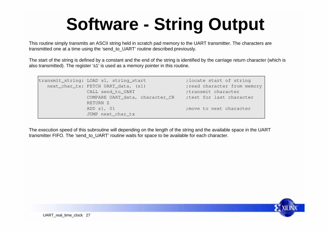
Software - String OutputThis routine simply transmits an ASCII string held in scratch pad memory to the UART transmitter. The characters aretransmitted one at a time using the ‘send_to_UART’ routine described previously.
The start of the string is defined by a constant and the end of the string is identified by the carriage return character (which isalso transmitted). The register ‘s1’ is used as a memory pointer in this routine.
transmit_string: LOAD s1, string_start ;locate start of string next_char_tx: FETCH UART_data, (s1) ;read character from memory CALL send_to_UART ;transmit character COMPARE UART_data, character_CR ;test for last character RETURN Z ADD s1, 01 ;move to next character JUMP next_char_tx
The execution speed of this subroutine will depending on the length of the string and the available space in the UARTtransmitter FIFO. The ‘send_to_UART’ routine waits for space to be available for each character.

UART_real_time_clock 28
Software - ClockAlthough the main application focus of this reference design provides a real time clock, the code for this is actually of lessinterest to analyze and would be less likely to be used in another application. For this reason, only small sections of code aredescribed to make some useful observations. update_time: STORE s0, time_preserve0
STORE s1, time_preserve1 STORE s2, time_preserve2 STORE s3, time_preserve3 STORE s4, time_preserve4 STORE s5, time_preserve5
Transparent Processing
The ‘update_time’ routine is a significant section of code which iscalled from various points in the program. The routine requiresseveral ‘working registers’. Since it would become difficult tomanage the use of these registers when dealing with other parts ofthe program, the routine is made effectively ‘transparent’ bypreserving the contents of all the used registers in scratch padmemory during the routine.
The store and fetch instructions clearly take some code space andrequire time to execute, but this technique will make applicationsvery portable and safe to use. This would be particularly useful forinterrupt service routines requiring significant processing.
finish_update: FETCH s0, time_preserve0 FETCH s1, time_preserve1 FETCH s2, time_preserve2 FETCH s3, time_preserve3 FETCH s4, time_preserve4 FETCH s5, time_preserve5 RETURN
S0 to s5 free to be used
SUB s4, s2SUBCY s5, s3FETCH s2, us_time_lsbFETCH s3, us_time_msbADD s2, s4ADDCY s3, s5
16-bit operations
[s5,s4] = [s5,s4] - [s3,s2]
Interrupt countertime (µs)
[s5,s4][s3,s2]
The ‘µs’ and ‘ms’ values of real time are handled as 16-bit quantities. The ability to include the CARRY flag in arithmeticoperations makes it possible to perform the 16-bit calculations that are required. In each case the LS-Bytes are processed first(without carry) and the carry incorporated into the processing of the MS-Bytes.
Elapsed time(µs)Calculate number of ‘µs’ elapsed since last
update. This could be up to 65,536µs.
[s3,s2] = [s3,s2] + [s5,s4]Add elapsed ‘µs’ to the real time total of ‘µs’.

UART_real_time_clock 29
Software - ClockThe seconds, minutes, and hours operation is just a classic example of assembler programming. This section of code beginswith the value ‘00’ or ‘01’ in the ‘s0’ register indicating the requirement to add one second of real time.
FETCH s1, real_time_seconds ADD s1, s0 COMPARE s1, seconds_in_a_minute JUMP Z, inc_minutes STORE s1, real_time_seconds JUMP time_update_completeinc_minutes: LOAD s1, 00 STORE s1, real_time_seconds FETCH s1, real_time_minutes ADD s1, 01 COMPARE s1, minutes_in_an_hour JUMP Z, inc_hours STORE s1, real_time_minutes JUMP time_update_complete inc_hours: LOAD s1, 00 STORE s1, real_time_minutes FETCH s1, real_time_hours ADD s1, 01 COMPARE s1, hours_in_a_day JUMP Z, reset_hours STORE s1, real_time_hours JUMP time_update_completereset_hours: LOAD s1, 00 STORE s1, real_time_hours
Note that the actual code includes comments. These are alwaysworth adding to your code to increase the understandability ofthe code especially when you return to it several weeks ormonths later. However, it is advisable to keep comments briefotherwise log files can become difficult to print.
Value Constants make the code easier to read and understandand are used here in the COMPARE instructions which actuallyperform a subtraction, discard the result, but still set the flags.Equal values will therefore cause the ZERO flag to be set.
Scratch pad memory and location constants.The memory provided the main variable storage for the realtime clock application and the registers are only used on atemporary basis. The use of location constants makes themeaning of each location obvious leading to very readable codewhich is portable.
Line labels are so easy to use and again help readability of thecode. It is most unusual to use absolute address values in anyJUMP or CALL instruction. Whilst it is useful to use descriptivelabels, try to keep them brief to help formatting.
UART_real_time_clock 30
Future Plans and ExercisesSince the main purpose of this package was as a reference design, there is no commitment to further enhance this as a design.However, if user feedback indicates that this is a useful ‘IP core’ in itself, there may be further development. At this time, it is leftto the reader to modify this reference design to provide any required functionality. Your feedback will be very useful in improvingthe reference design for both educational and IP requirements.
It is suggested that the addition of the following features would provide suitable self training opportunities.
Future Plans
Exercises
Similar to setting a home VCR or central heating controller, provide the ability to program the clock with a start timeand an end time which results in an output pin being turned ‘on’ during the specified times. Hardware - Add an additional output port. Software - interpret new command string and implement another time value in scratch pad memory.
Start/Stop Timer
Modify the existing design to…..1) Operate at a baud rate of 9600 - Hardware change only.2) Provide an interrupt at 10µs intervals - Hardware and software changes (ISR).3) Make the alarm condition transmit a message to the terminal - Software change only.
Add support for day name and full date. My be you even know the way to compute the day from the date! Software - New command strings, messages and values stored in scratch pad memory.
Day/Date support
UART_real_time_clock 31
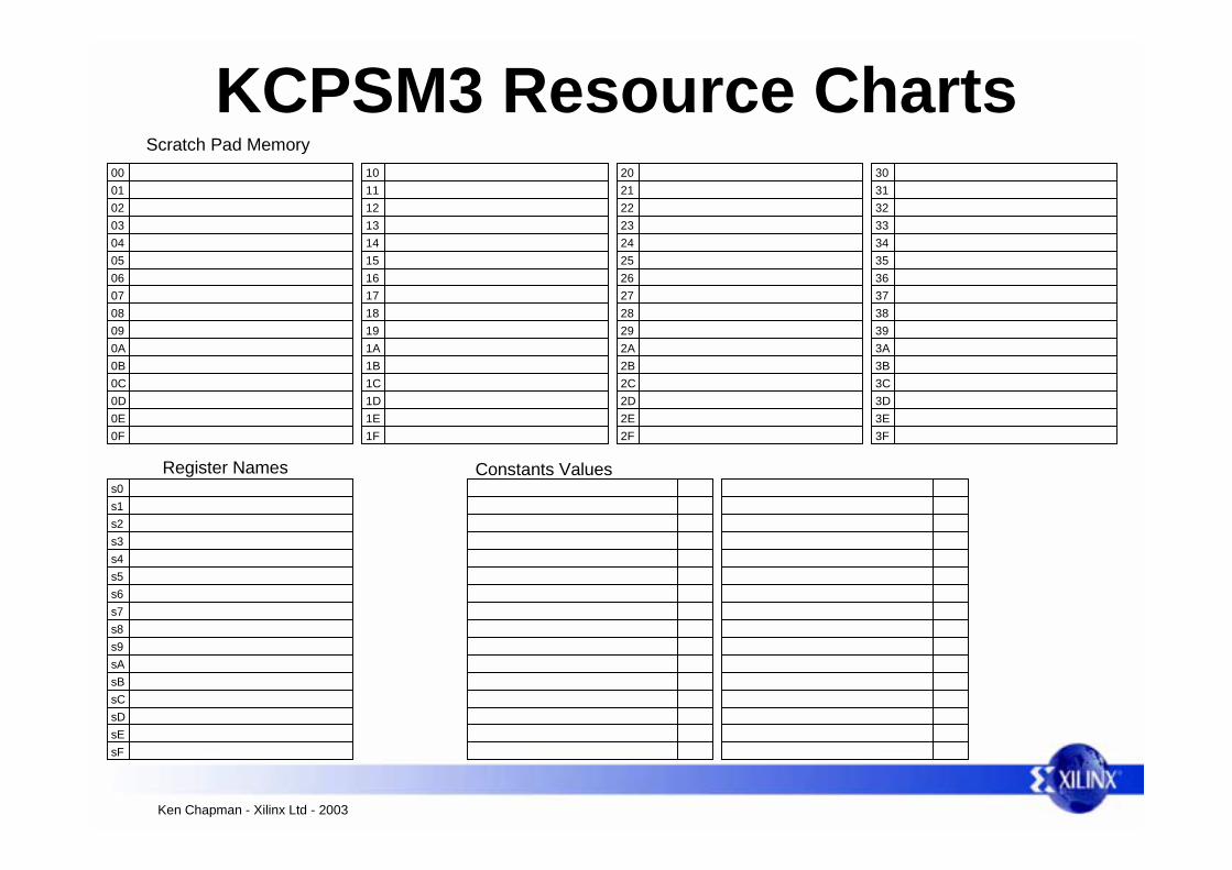
KCPSM3 Resource Charts
Ken Chapman - Xilinx Ltd - 2003
Scratch Pad Memory000102030405060708090A0B0C0D0E0F
101112131415161718191A1B1C1D1E1F
202122232425262728292A2B2C2D2E2F
303132333435363738393A3B3C3D3E3F
Register Namess0s1s2s3s4s5s6s7s8s9sAsBsCsDsEsF
Constants Values