Embed Size (px)
Citation preview

e,(~DUKE ~ ENERGY®
CNS-16-022
March 31, 2016
Attention: Document Control Desk U. S. Nuclear Regulatory Commission Washington, D. C. 20555-001
Duke Energy Carolinas, LLC (Duke Energy) Catawba Nuclear Station (CNS), Units 1 and 2 Docket Number(s) 50-413 and 50-414 Renewed License Nos. NPF-35 and NPF-52
Kelvin Henderson
Vice President
Catawba Nuclear Station
Duke Energy
CN01VP 14800 Concord Road
York, SC 29745
o: 803.701.4251 f: 803.701.3221
10 CFR 50.4 10 CFR 2.202(b)
Subject: Supplemental Information to the Final Notification of Full Compliance with Order EA,. 12-049, "Order Mo.difying Licenses with Regard to. Requirements for Mitigation Strategies for Beyond Design Basis External Events" and with Order EA-12-051, "Order to Modify Licenses With Regard To Reliable Spent Fuel Pool Instrumentation" for 'catawba Nuclear Station · ·
References:
1. Nuclear Regulatory Commission (NRC) Order Number EA-12-049, Order Modifying Licensees With Regard to Requirements for Mitigation Strategies for Beyond-DesignBasis External Events, Revision 0, dated March 12, 2012, Agencywide Documents Access and Management System (ADAMS Accession No. ML 12054A735)
2. NRC Order Number EA-1_2-051, Order to Modify Licenses With Regard To Reliable Spent Fuel Pool Instrumentation, dated March 12,. 2012 (ADAMS Accession No. ML 12054A679)
3. Catawba Nuclear Station, Units 1 and 2, Final Notification of Full Compliance with Order EA-12-049, "Order Modifying Licenses with Regard to Requirements for Mitigation Strategies for Beyond Design Basis External Events" and with Order EA-12-051, "Order to Modify Licenses With Regard To Reliable Spent Fuel Pool Instrumentation" for Catawba Nuclear Station, dated February 15, 2016 (ADAMS Accession No. ML 16049A041)
United States Nuclear Regulatory Commission Page2 March 31, 2016
Ladies and Gentlemen
On March 12, 2012, the Nuclear Regulatory Commission (NRC) issued Order EA-12-049, "Order Modifying Licenses with Regard to Requirements for Mitigation Strategies for Beyond Design-Basis External Events" and Order EA-12-051, "Order to Modify Licenses With Regard To Reliable Spent Fuel Pool Instrumentation," (Reference 1 and Reference 2, respectively).
On February 15, 2016, Duke Energy provided the NRC staff with the Final Notification of Full Compliance with Order EA-12-049, "Order Modifying Licenses with Regard to Requirements for Mitigation Strategies for Beyond Design Basis External Events" and with Order EA-12-051, "Order to Modify Licenses With Regard To Reliable Spent Fuel Pool Instrumentation" for Catawba Nuclear Station (Reference 3). A teleconference was held with the NRC staff on March 3, 2016, in which the NRC requested several items regarding Reference 3 to be placed on the Catawba Nuclear Station docket. Specifically, the information requested pertained to Attachments 3 and 4 of Reference 3. Attachments 3 and 4 of Reference 3 a·re provided as attachments to this letter per the NRC request made in the teleconference dated March 3, 2016. Attachments 1, 2, 5, 6, and 7 of the Final Notification Letter (Reference 3) remain unchanged.
There are no regulatory commitments contained in this letter or its attachments. Please address any comments or questions regarding this matter to Cecil Fletcher at 803-701-3622.
I declare under penalty of perjury that the foregoing is true and correct. Executed on March 31, 2016.
Sincerely,
Kelvin Henderson, Vice President, Catawba Nuclear Station
Enclosures: Attachment 3: CNS Response to Diverse and Flexible Strategies Interim Staff Evaluation Open and Confirmatory Items
Attachment 4: CNS Response to Request for Additional Information Regarding the Overall Integrated Plan for Implementation of Order EA-12-051, Reliable Spent Fuel Pool Instrumentation

United States Nuclear Regulatory Commission Page3 March 31, 2016
xc:
C. Haney, Regional Administrator U. S. Nuclear Regulatory Commission, Region II Marquis One Tower 245 Peachtree Center Avenue NE, Suite 1200 Atlanta, GA 30303-1257
W. M. Dean, Director, Office of Nuclear Reactor Regulation US. Nuclear Regulatory Commission One White Flint North, Mailstop 13 Hl6M 11555 Rockville Pike Rockville, MD 20852-2738
J.A. Whited, Project Manager U.S. Nuclear Regulatory Commission One White Flint North, Mailstop 8 B1A 11555 Rockville Pike Rockville, MD 20852-2738
P.J. Bamford, Senior Project Manager U.S. Nuclear Regulatory Commission One White Flint North, Mailstop 13 F15 11555 Rockville Pike Rockville, MD 20852-2738
G.A. Hutto, Ill NRC Senior Resident Catawba Nuclear Station
Justin Folkwein American Nuclear Insurers 95 Glastonbury Blvd., Suite 300 Glastonbury, CT 06033-4453

Attachment 3
CNS RESPONSE TO DIVERSE AND FLEXIBLE STRATEGIES INTERIM STAFF EVALUATION OPEN AND CONFIRMATORY ITEMS
Duke Energy provides the following response to the Interim Staff Evaluation (ISE) open and confirmatory items contained in NRC Letter, "CNS - Interim Staff Evaluation Relating to the Overall Integrated Plan in Response to Order EA-12-049 (Mitigation Strategies), (Agency-wide Documents Access and Management System (ADAMS Accession No. ML 13364A 175).
0 en Items
3.1.2.2.A
3.2.1.8.A
Resolve the conflict between the need to pump the TDAFW pump pit before submergence at 6 hours and deploying generators to power the sump pumps by 8 hours.
Core Sub-Criticality:..Confirm resolution of the generic concern associated with the modeling of the timing and uniformity of the mixing of a liquid boric acid solution injected .into the reactor coolant system under natural circulation conditions potentially involving two-phase flow.
The TDAFW sump pit pump is powered from one of the smaller 6 Kw generators and not the larger 500 Kw generator which is .deployed around 8 hours. FG/O/A/CFLX/FSG-22 (Sump Pump Operation) positions the 6 Kw generator and portable sump pump.
The NRC has endorsed the PWROG white paper, dated August 15, 2013, that discusses boron mixing under natural circulation conditions with three clarifications (from ADAMS No. ML 13276A183 and shown in Westinghouse LTR-LIS-14-79 which is contained in DPC-1552.08-00-0278). Catawba has addressed these concerns in the ELAP boration analysis, DPC-1552.08-00-0278. Injection will be started before the two-phased natural circulation loop flow is less than the single phase natural circulation flow rate (using NOTRUMP results from Table 6-1 of PWROG-14027-P), and credit for increasing the RCS boron concentration has been delayed by one hour to account for the mixing of the borated makeup with the RCS inventory.
Page 1of8
Attachment 3
CNS RESPONSE TO DIVERSE AND FLEXIBLE STRATEGIES INTERIM STAFF EVALUATION OPEN AND CONFIRMATORY ITEMS
Confirmatorv Items
Cof'!firQlatory -·. 1t~m# -.
3.1.1.2.A
3.1.1.3.A
3.2.1.1.A
. -~ - ' . - ' -_ -" _, _.- ; ~ -.. :.:~· _- __ ~'-
. ,, --, _ , __ Item £iesf_ripti9n -~~d)~~(:ti~n · · , .. )',: :~:
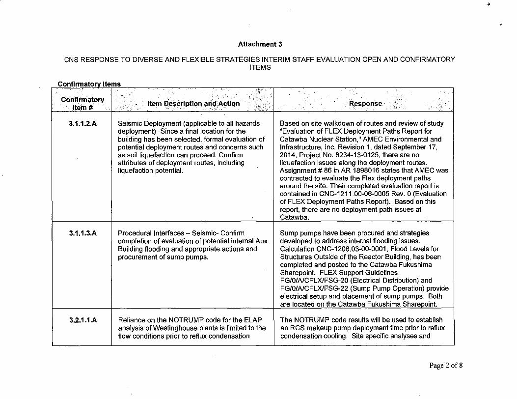
Seismic Deployment (applicable to all hazards deployment) -Since a final location for the building has been selected, formal evaluation of potential deployment routes and concerns such as soil liquefaction can proceed. Confirm attributes of deployment routes, including liquefaction potential.
Procedural Interfaces - Seismic- Confirm completion of evaluation of potential internal Aux Building flooding and appropriate actions and procurement of sump pumps.
Reliance on the NOTRUMP code for the ELAP analysis of Westinghouse plants is limited to the flow conditions prior to reflux condensation
-·-' ~esponse - _ ''. _: _
Based on site walkdown of routes and review of study "Evaluation of FLEX Deployment Paths Report for Catawba Nuclear Station," AMEC Environmental and Infrastructure, Inc. Revision 1, dated September 17, 2014, Project No. 6234-13-0125, there are no liquefaction issues along the deployment routes. Assignment# 86 in AR 1898016 states that AMEC was contracted to evaluate the Flex deployment paths around the site. Their completed evaluation report is contained in CNC-1211.00-06-0005 Rev. 0 (Evaluation of FLEX Deployment Paths Report). Based on this report, there are no deployment path issues at Catawba.
Sump pumps have been procured and strategies developed to address internal flooding issues. Calculation CNC-1206.03-00-0001, Flood Levels for Structures Outside of the Reactor Building, has been completed and posted to the Catawba Fukushima Sharepoint. FLEX Support Guidelines FG/O/A/CFLX/FSG-20 (Electrical Distribution) and FG/O/A/CFLX/FSG-22 (Sump Pump Operation) provide electrical setup and placement of sump pumps. Both are located on the Catawba Fukushima Sharepoint.
The NOTRUMP code results will be used to establish an RCS makeup pump deployment time prior to reflux condensation cooling. Site specific analyses and
Page 2 of8

Attachment 3
CNS RESPONSE TO DIVERSE AND FLEXIBLE STRATEGIES INTERIM STAFF EVALUATION OPEN AND CONFIRMATORY ITEMS
3.2.1.3.A
initiation. This includes specifying an acceptable definition for reflux condensation cooling. Confirm that the NOTRUMP code is used within the accepted limits.
Westinghouse will be assisting CNS in providing further information regarding decay heat modeling. Evaluate for applicability and implementation. ·
accepted definitions for reflux condensation cooling are contained in DPC-1552.08-00-0278, Rev. 3.
A complete listing of the assumptions that were used to arrive at the normalized decay heat power can be found in L TR-LIS-14-219, and have been confirmed to be applicable for Catawba. The decay heat used for the Westinghouse nuclear steam supply system (NSSS) calculations documented in WCAP-17601-P, Rev. 1 (Reference 1) and WCAP-17792 (Reference 3) using the NOTRUMP code was calculated per ANS 5.1 1979. The following assumptions were applied to arrive at the overall normalized decay heat power: Two standard deviations of uncertainty(+ 2 sigma). Three fissile isotopes of U-235, Pu-239 and U-238. The total recoverable energy associated with one fission for each isotope is assumed to be 201.8 MeV, 210.3 MeV and 205.0 MeV, respectively. The power fractions are typical values expected for each of the three fissile isotopes through a three region burn-up with which the feed fuel U-235 enrichment is - 5%, which is typical of fuel cycle feeds. Actinide contributions to the decay heat are from U-239 and Np-239.A conversion ratio of 0.65 was used to derive the production of the two actinides: U-239 and Np-239. Fission product neutron capture is treated per the ANS standard. Finite burnup that utilizes a power history of three 540 day cycles se arated b two 20 da outa es that bounds initial
Page 3of8
Attachment 3
CNS RESPONSE TO DIVERSE AND FLEXIBLE STRATEGIES INTERIM STAFF EVALUATION OPEN AND CONFIRMATORY ITEMS
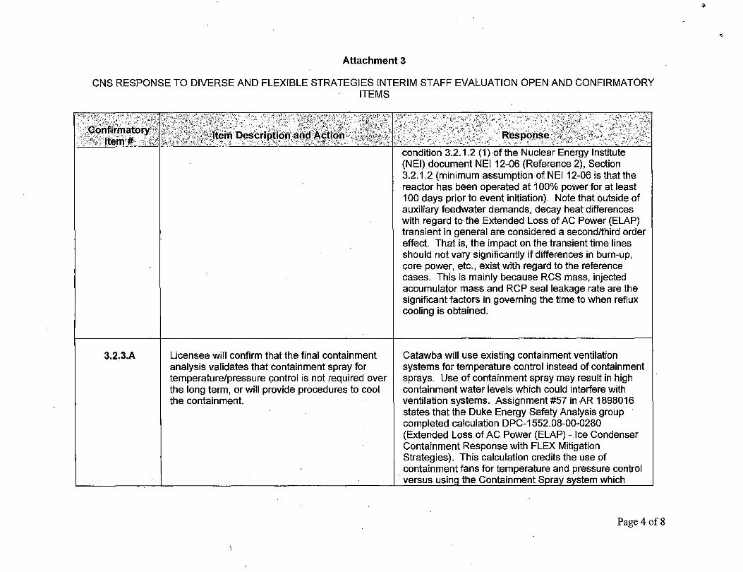
3.2.3.A Licensee will confirm that the final containment analysis validates that containment spray for temperature/pressure control is not required over the long term, or will provide procedures to cool the containment.
condition 3.2.1.2 (1 )-of the Nuclear Energy Institute (NEI) document NEI 12-06 (Reference 2), Section 3.2.1.2 (minimum assumption of NEI 12-06 is that the reactor has been operated at 100% power for at least 100 days prior to event initiation). Note that outside of auxiliary feedwater demands, decay heat differences with regard to the Extended Loss of AC Power (ELAP) transient in general are considered a second/third order effect. That .is, the impact on the transient time lines should not vary significantly if differences in burn-up, core power, etc., exist with regard to the reference cases. This is mainly because RCS mass, injected accumulator mass and RCP seal leakage rate are the significant factors in governing the time to when reflux cooling is obtained.
Catawba will use existing containment ventilation systems for temperature control instead of containment sprays. Use of containment spray may result in high containment water levels which could interfere with ventilation systems. Assignment #57 in AR 1898016 states that the Duke Energy Safety Analysis group completed calculation DPC-1552.08-00-0280 (Extended Loss of AC Power (ELAP) - Ice Condenser Containment Response with FLEX Mitigation Strategies). This calculation credits the use of containment fans for temperature and pressure control
· versus using the Containment Spray s stem which
Page 4 of8

Attachment 3
CNS RESPONSE TO DIVERSE AND FLEXIBLE STRATEGIES INTERIM STAFF EVALUATION OPEN AND CONFIRMATORY ITEMS
Confirmatory Item Description arid Action Response Item#
would have been marginal using portable pumps and the issue of additional flooding in containment created by using the spray system. DPC-1552.08-00-0280 recommends that 1 Hydrogen Skimmer fan be placed in service by 24 hours, 2 Lower Containment Ventilation fans be placed in service by 48 hours, and 1 Containment Air Return fan be placed in service by 52 hours to control containment and compartment temperatures and pressures to within acceptable values.
3.2.4.1.A Room temperature analyses being performed will Catawba has purchased sufficient fans and spot provide a better idea of the environmental coolers to perform phase 1, 2, and 3 strategies, provide conditions expected during the event. Confirm sufficient cooling for equipment operation/personnel completion of analyses and appropriate actions. habitability, and hydrogen gas control based on Gothic
analysis performed by Zachry (Reference CNC-1211.00-00-0146 - Gothic Analysis for Extended Loss Of All AC Power (ELAP/FLEX)). Procedural guidance has been developed to implement the mitigation recommendations in the Zachry analyses. In addition, per Table 7-1 in the SAFER Response Plan for Catawba Nuclear Station Rev. 002 (AREVA Document No. 38-9233743-000), Catawba will receive one 3000 cfm ventilation fan and associated ducting per Unit from the NSRC. This ventilation equipment from the NSRC will be used on as needed/as desired basis to provide additional air flow to any area in the plant.
Page 5of8

Attachment 3
CNS RESPONSE TO DIVERSE AND FLEXIBLE STRATEGIES INTERIM STAFF EVALUATION OPEN AND CONFIRMATORY ITEMS
Confirmatory , Item#
3.2.4.3.A
..,.. • •" J ,
lt~m Des?ription an~:Actic;m'· ·,· . /, ,.
Evaluations to address the needs for freeze protection are in progress. Confirm completion of evaluations and appropriate actions.
.'.';
Response
Other than components associated with monitoring FWST level, there is no other Flex related instrumentation located in the yard. The FWST level instrumentation is exposed and is normally freeze protected. As noted below, heat tracing equipment is kept in the Flex storage building and can be used to keep the FWST level instrumentation functional in extreme freezing conditions as directed by the FSGs.
Some credited instrumentation components are located in the Doghouses, but they will not require freeze protection. During cold weather conditions the window sections of the Doghouses are covered by curtains. This, combined with heat by steam piping used in the Phase 1 and 2 response, eliminates freezing of instruments or impact to supporting equipment. Flex piping connections were reviewed and none were found to be affected by outside freezing conditions. Auxiliary Feedwater and Steam Generator Wet Layup (BW) connections in the Doghouse are "protected" in the same manner as the instrumentation discussed above. Most Flex piping connections are located in the Auxiliary Building where freezing is not credible. One train of RN connection is located outside, but within a below grade bunker. Inventory used from the FWST enters the plant through the normal system piping. Based on initial conditions and the design of the piping system, freezing is not projected to be a problem. Only the piping in the trench leaving the FWST is considered
Page 6 of8

Attachment 3
CNS RESPONSE TO DIVERSE AND FLEXIBLE STRATEGIES INTERIM STAFF EVALUATION OPEN AND CONFIRMATORY ITEMS
Confirmatory Item Description and Action Response Item# for use in the FLEX response. This piping along with the FWST is judged to be weather protected to the extent that freezing will not occur before FLEX strategies are implemented. The Fuel Building will remain above freezing due to the constant heat source of the spent fuel in the pool.
As a contingency, Catawba has a roll of heating cable stored in the protected storage building. This self-regulating heat trace cable is provided along with the accessories for assembling multiple freeze protection circuits. These heating cables could be powered from any portable DIG supplying 120 VAC power. This equipment could be deployed if an unanticipated freeze protection need developed.
3.2.4.4.A Confirm evaluations for additional lighting have Lighting assessment has been completed and is been completed (licensee's open item 45 and available on the Catawba Fukushima Sharepoint for 59), and appropriate actions taken. review.
3.2.4.4.B Confirm upgrades to the site's communication AR 01495465 was written to address NTTF systems have been completed. Recommendation 9.3 related to Communications.
Assignments 10, 15, and 16 in this AR specifically address the following:
1. Training on the use and maintenance of satellite phones and portable radios
2. Improvements for communications with offsite response orQanizations bv ensurinQ each
Page 7of8
t

Attachment 3
CNS RESPONSE TO DIVERSE AND FLEXIBLE STRATEGIES INTERIM STAFF EVALUATION OPEN AND CONFIRMATORY ITEMS
Confii'matory item#
3.4.A
' - : ,_
Item Description ·and Actio~n ' ·.. ' "- -, __ ' < .... ,_,
Offsite Resources -Confirm NEI 12-06 Section 12.2, Guidelines 2 through 1 O are addressed with SAFER
Complete SAFER Site specific plan.
Response , , . < -
organization has satellite phones
3. Procedures for maintenance of equipment (radios & satellite phones)
4. Training on location, use and maintenance of satellite phones & portable radios.
Details related to these items can be found in the Assignments contained in AR 01495465. A copy of PT/O/B/4600/123 and PT/O/B/4600/004 is on the SharePoint.
Approved CNS SAFER Plan, CNSRP-1612.03-01, has been posted to the Catawba Fukushima SharePoint for review.
Page 8of8

Attachment 4
CNS RESPONSE TO REQUEST FOR ADDITIONAL INFORMATION REGARDING THE OVERALL INTEGRATED PLAN FOR IMPLEMENTATION OF ORDER EA-12-051, RELIABLE
SPENT FUEL POOL INSTRUMENTATION
By letter dated February 28, 2013, Duke Energy Carolinas, LLC (Duke Energy) submitted an Overall Integrated Plan (OIP) in response to the March 12, 2012; Nuclear Regulatory Commission (NRG) Order, "Order Modifying Licenses with Regard to Reliable Spent Fuel Pool (SFP) Instrumentation (Order Number EA-12-051)," for Catawba Nuclear Station (CNS), Units 1 and 2 (ADAMS Accession No. ML 13086A095). On October 28, 2013, the NRG issued an interim staff evaluation (ISE) and request for additional information (RAI) regarding the CNS OIP for implementation of NRG Order EA-12-051, Reliable Spent Fuel Pool Instrumentation (ADAMS Accession No. ML 13281A562). Subsequently, by letter dated March 26, 2014, the NRG staff advised each licensee participating in the audit to place the RAI responses and other supporting information on the site ePortal by the date identified in the ISE (ADAMS Accession No. ML 14083A620). CNS Reponses to the October 28, 2013, RAls were posted on the ePortal by the requested date. The CNS RAI response has been revised as a result of discussions that occurred during the NRG staffs audit in September 2014 of CNS's ongoing work for the implementation of mitigating strategies and reliable spent fuel pool instrumentation for compliance with Orders EA-12-049 and EA-12-051. The revised RAI responses are provided below, which reflect the final completed status of all actions necessary to achieve full compliance with Order Number EA-12-051.
Page 1of33

l't-
Attachment 4
CNS RESPONSE TO REQUEST FOR ADDITIONAL INFORMATION REGARDING THE OVERALL INTEGRATED PLAN FOR IMPLEMENTATION OF ORDER EA-12-051, RELIABLE
SPENT FUEL POOL INSTRUMENTATION
RAl-1
Please confirm that 597 ft. 6 in. is the correct elevation provided for Level 1.
RAl-1 Response
Level 1 elevation is 597 ft. 6 in.
The official response to this RAI was submitted with the Catawba Second Six Month Update dated Feb 26, 2014 (Ref. ADAMS Accession No. ML 14063A279).
Page 2of33
Attachment 4
CNS RESPONSE TO REQUEST FOR ADDITIONAL INFORMATION REGARDING THE OVERALL INTEGRATED PLAN FOR IMPLEMENTATION OF ORDER EA-12-051, RELIABLE
SPENT FUEL POOL INSTRUMENTATION .
RA1~2
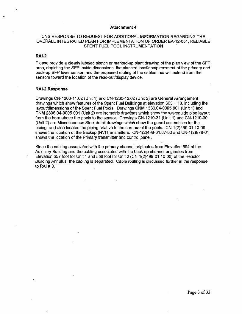
Please provide a clearly labeled sketch or marked-up plant drawing of the plan view of the SFP area, depicting the SFP inside dimensions, the planned locations/placement of the primary and back-up SFP level sensor, and the proposed routing of the cables that will extend from the sensors toward the location of the read-out/display device.
RAl-2 Response
Drawings CN-1200-11.02 (Unit 1) and CN-1200-12.02 (Unit 2) are General Arrangement drawings which show features of the Spent Fuel Buildings at elevation 605. + 10, including the layout/dimensions of the Spent Fuel Pools. Drawings CNM 1336.04-0005 001(Unit1) and CNM 2336.04-0005 001 (Unit 2) are isometric drawings which show the waveguide pipe layout from the horn above the pools to the sensor. Drawings CN-1210-31 (Unit 1) and CN-1210-30 (Unit 2) are Miscellaneous Steel detail drawings which show the guard assemblies for the piping, and also locates the piping relative to the corners of the pools. CN-1(2)499-01.10-00 shows the location of the Backup (NV) transmitters. CN-1 (2)499-01.07-00 and CN-1 (2)878-01 shows the location of the Primary transmitter and control panel.
Since the cabling associated with the primary channel originates from Elevation 594 of the Auxiliary Building and the cabling associated with the back up channel originates from Elevation 557 foot for Unit 1 and 556 foot for Unit 2 (CN-1(2)499-01.10-00) of the Reactor Building Annulus, the cabling is separated. Cable routing is discussed further in the response to RAI # 3.
Page 3 of33
•
·-Attachment 4
CNS RESPONSE TO REQUEST FOR ADDITIONAL INFORMATION REGARDING THE OVERALL INTEGRATED PLAN FOR IMPLEMENTATION OF ORDER EA-12-051, RELIABLE
SPENT FUEL POOL INSTRUMENTATION
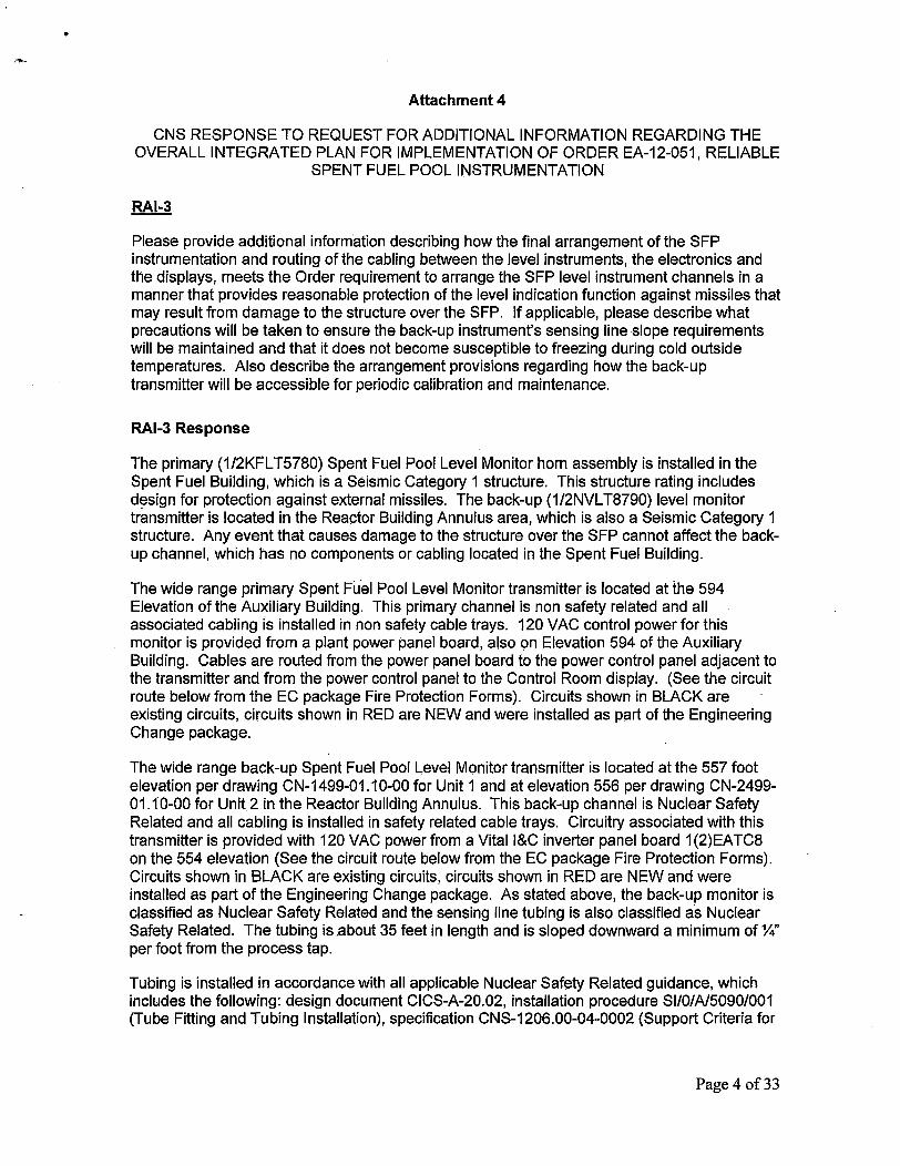
Please provide additional information describing how the final arrangement of the SFP instrumentation and routing of the cabling between the level instruments, the electronics and the displays, meets the Order requirement to arrange the SFP level instrument channels in a manner that provides reasonable protection of the level indication function against missiles that may result from damage to the structure over the SFP. If applicable, please describe what precautions will be taken to ensure the back-up instrument's sensing line slope requirements will be maintained and that it does not become susceptible to freezing during cold outside temperatures. Also describe the arrangement provisions regarding how the back-up transmitter will be accessible for periodic calibration and maintenance.
RAl-3 Response
The primary (1/2KFLT5780) Spent Fuel Pool Level Monitor horn assembly is installed in the Spent Fuel Building, which is a Seismic Category 1 structure. This structure rating includes d~sign for protection against external missiles. The back-up (1/2NVL T8790) level monitor transmitter is located in the Reactor Building Annulus area, which is also a Seismic Category 1 structure. Any event that causes damage to the structure over the SFP cannot affect the backup channel, which has no components or cabling located in the Spent Fuel Building.
The wide range primary Spent Fu.el Pool Level Monitor transmitter is located at the 594 Elevation of the Auxiliary Building. This primary channel is non .safety related and all associated cabling is installed in non safety cable trays. 120 VAC control power for this monitor is provided from a plant power panel board, also on Elevation 594 of the Auxiliary Building. Cables are routed from the power panel board to the power control panel adjacent to the transmitter and from the power control panel to the Control Room display. (See the circuit route below from the EC package Fire Protection Forms). Circuits shown in BLACK are existing circuits, circuits shown in RED are NEW and were installed as part of the Engineering Change package.
The wide range back-up Spent Fuel Pool Level Monitor transmitter is located at the 557 foot elevation per drawing CN-1499-01.10-00 for Unit 1 and at elevation 556 per drawing CN-2499-01.10-00 for Unit 2 in the Reactor Building Annulus. This back-up channel is Nuclear Safety Related and all cabling is installed in safety related cable trays. Circuitry associated with this transmitter is provided with 120 VAC power from a Vital l&C inverter panel board 1 (2)EATC8 on the 554 elevation (See the circuit route below from the EC package Fire Protection Forms). Circuits shown in BLACK are existing circuits, circuits shown in RED are NEW and were installed as part of the Engineering Change package. As stated above, the back-up monitor is classified as Nuclear Safety Related and the sensing line tubing is also classified as Nuclear Safety Related. The tubing is .about 35 feet in length and is sloped downward a minimum of%" per foot from the process tap.
Tubing is installed in ac.cordance with all applicable Nuclear Safety Related guidance, which includes the following: design document CICS-A-20.02, installation procedure Sl/O/A/5090/001 (Tube Fitting and Tubing Installation), specification CNS-1206.00-04-0002 (Support Criteria for
Page 4 of33

•
Attachment 4
CNS RESPONSE TO REQUEST FOR ADDITIONAL INFORMATION REGARDING THE OVERALL INTEGRATED PLAN FOR IMPLEMENTATION OF ORDER EA-12-051 , RELIABLE
SPENT FUEL POOL INSTRUMENTATION
Construction Tubing Slope), IP/O/A/3850/006 (Controll ing Procedure for Installation of Tube Supports) and specification CNS-1206.00-04-006 (Civil Specification, Routing and Support of Tubing) .
An analysis of ELAP temperatures in areas adjacent to the annulus shows that the lower annulus area should not be subject to freezing during cold outside temperatures. There are a number of transmitters associated with different plant systems currently located in the lower annulus area. Most of these devices are routinely accessed for calibration and maintenance. The pressure transmitter for Spent Fuel Pool Level will also be accessible, as needed.
Cable Routing for EC109413
----- -----AUX 594 KK-64
I 2KPX BKR 20 I
Fire Area 22 I 20Amp I
TB2 594 2N-32 I 2KFLT5780 I I 2VA848
I
4SPX I I I 2KF574 2ATC12 2RN864 2TDC2
2ELCP0365 I 2KF575 AUX 594 NN-60 AUX 574 88-59 ' I Fire Area 22 Fire Area 16
I I I 2KF573 2SPX I L 2DRTC12 I
2KFP5781 I AUX 577 GG-60 I Fire Area 18 2W 734 I - - --------
r----- --- ------ -- --- - - - - -I I 2MC7 I 2MC3 I 2KFP5780 - AUX 594 AA-58 I I AUX 594 88-58
M ain Control Board
I Fire Area 21
---------------------------
Page 5of 33

Attachment 4
CNS RESPONSE TO REQUEST FOR ADDITIONAL INFORMATION REGARDING THE OVERALL INTEGRATED PLAN FOR IMPLEMENTATION OF ORDER EA-12-051 , RELIABLE
SPENT FUEL POOL INSTRUMENTATION
r---------1 AUX 594 KK-50
Fire Area 22 CN-1209-10.14
1KFLT5780
1KFP5781
JNVLT8790
Cable Routing for EC109414
1KF574
1KF575
1KF573
lKPX BKR 20 20Amp
TBl 594 lN-32
1VA848
1ATC12 1TDC2 AUX 594 MM-53 t---1R_N_8_64--t AUX 574 BB-55
Fire Area 22 Fire Area 17 CN- 1209-10.14 CN-1 209-10.13
1DRTC12 AUX 577 GG-54
Fire Area 18 CN-1209-10.13
1W734
r- ------ ------------1MC7
1KFP5780 AUX 594 BB-56
1MC3 AUX 594 AA-56
Main Control Board Fire Area 21
CN-1209-10.14
Ca ble Routing fo r EC110934
lERPA BKR 10 20Amp
Aux 554 00-55
Fire Arn lO CN-1209-10.12
l*VF685
1EATC8 llCS Unrt l AMufus 1 • NV1061 AUX 5 77£E-55 1 * ATC1086 AUX 574 00-55
frrr A•u 1R6- Fore Area 22 Fire Area 17 CN· 209-10 19 CN-1209-10.13 CN-1209-10.13
1• VES63
1- - - - - - - - - - - - - - - - - - - - - - -I I I I 1 I I
lMCS 1NVPV8790
AUX 594 BB-56
' Main Control Board I 1 Fire Area 21 I C -1209-10.14
1MC7 INVP8790
AUX 594 BB-56
~----------------------------'
Page 6of33
Attachment 4
CNS RESPONSE TO REQUEST FOR ADDITIONAL INFORMATION REGARDING THE OVERALL INTEGRATED PLAN FOR IMPLEMENTATION OF ORDER EA-12-051 , RELIABLE
SPENT FUEL POOL INSTRUMENTATION
2NVLT8790 Un·t 2 Ann lus fire Are. 2RB- ~
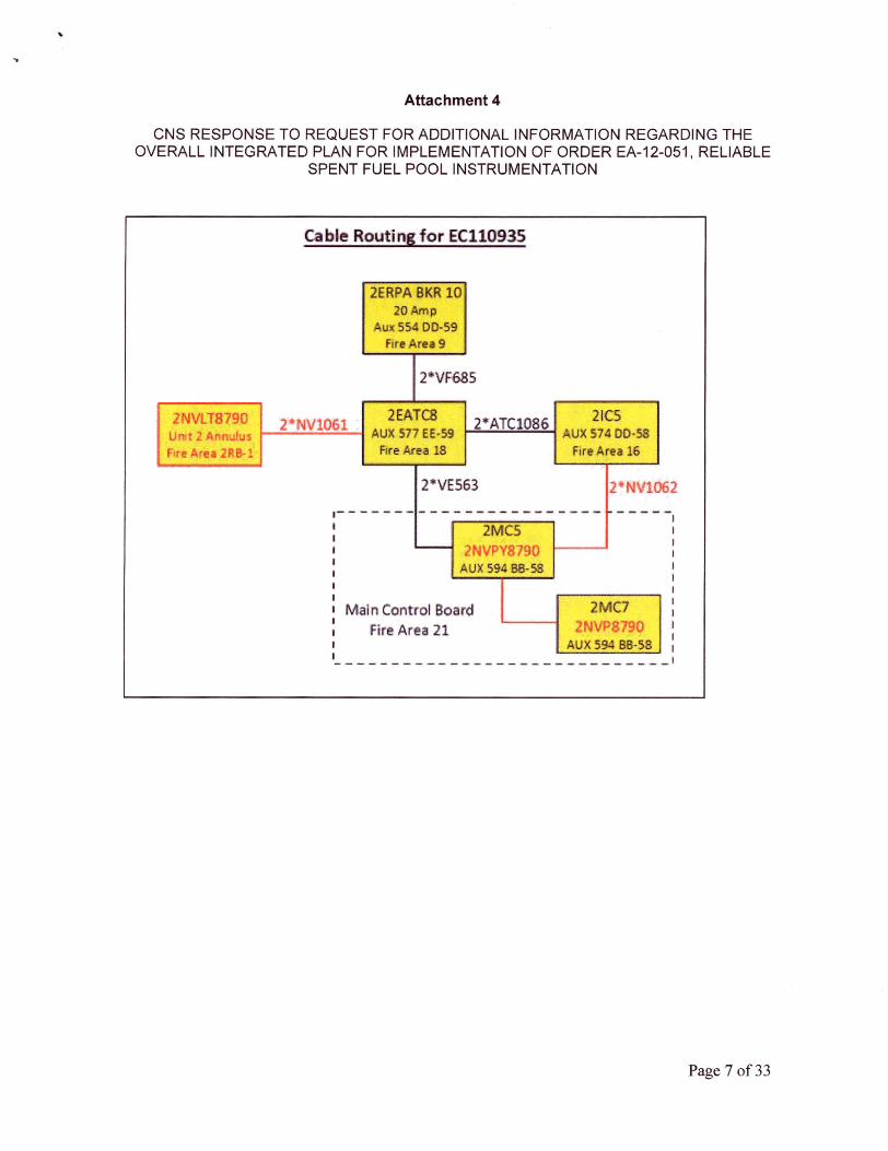
Cable Rout i ngfor EC110935
2ERPA BKR 10 20Amp
Aux 554 00·59 fire Area 9
2*VF685
2*NV106l 2EATC8 AUX 577 EE-59
Fire Area 18
2*ATC1086 ; AUX ;;;~O-SB 1 Fire Area 16
2 NV1062
---- - ---- --- -- -- - ~-- --- --- - 1 l 2MCS I
----j 2NVPV8790 AUX 594 BB-58
Mai n Control Board 2MC7 Fire Area 21 2NVP8790
1 AUX 594 BB-58 :
----- - -- -- ---- -- -- - --- -- -- -- - '
Page 7 of33

Attachment 4
CNS RESPONSE TO REQUEST FOR ADDITIONAL INFORMATION REGARDING THE OVERALL INTEGRATED PLAN FOR IMPLEMENTATION OF ORDER EA-12-051, RELIABLE
SPENT FUEL POOL INSTRUMENTATION
RAl-4
Please provide the following:
a) The design criteria that will be used to estimate the total loading on the mounting device(s), including static weight loads and dynamic loads.
Describe the methodology that will be used to estimate the total loading, inclusive of design basis maximum seismic loads and the hydrodynamic loads that could result from pool sloshing or other effects that could accompany such seismic forces.
b) A description of the manner in which the level sensor (and stilling well, if appropriate) will be attached to the refueling floor and/or other support structures for each planned point of attachment of the probe assembly. Indicate in a schematic the portions of the level sensor that will serve as points of attachment for mechanical/mounting or electrical connections. For the back-up pressure transmitter describe the sensing line and transmitter attachments to plant structures.
c) A description of the manner by which the mechanical connections will attach the level ,instrument to permanent SFP structures so as to support the level sensor assembly.
RAl-4 Response
a) The primary channel, which consists of the electronic transmitter, horn, and waveguide piping, is mounted seismically. The mounting designs for the electronic sensor support, horn support, and intermediate supports were qualified considering the total weight of the waveguide piping and its components and the seismic accelerations for the building structure. To meet the design criteria for a BOB Event, the loading for the mounting supports were generated using a minimum of 2 X SSE accelerations. The mounting designs for these supports are qualified by calculations using the Manual of Steel Construction AISC 9th Edition, Hilti Product Technical Guides, and site specific specifications. The electronic sensor mounting support is qualified by a generic calculation, CNC-1336.04-00-0002, using a simple C-channel steel section that is welded centrally on a Yz " thick steel base plate on the Auxiliary Building concrete wall. This Auxiliary Building wall is Seismic Category 1. The base plate is anchored to the wall with four (4) concrete anchor bolts. The generic sensor mounting support was designed for generic enveloping seismic accelerations of 1 Og (horizontal) and 6.67g (vertical), which readily 'envelopes the site specific response spectra. The calculation further assumed an enveloping sensor cantilevered length.
However, considering that this qualification uses very conservative generic accelerations compared to the 2 X SSE design criteria, design seismic accelerations were used which are less than the generic accelerations but are much greater than the 2 X SSE accelerations. Conservatively, 50% of the generic accelerations were used in the qualification for the anchorage of the electronic sensor mounting. This 50% reduction in the generic accelerations is still greater than the 2 X SSE design criteria accelerations. The specific concrete anchors used are qualified in calculation file CNC-1139.14-08-0001.
The Catawba horn cantilever mounting support consists of a C8X18.75 channel, HSS 3 X 3 X %"and a Yz" baseplate of dimensions 10" X 12". The base plate is designed to be anchored to the floor with four (4) concrete anchor bolts (Welds were used at the corners next to the pool,
Page 8of33

Attachment 4
CNS RESPONSE TO REQUEST FOR ADDITIONAL INFORMATION REGARDING THE OVERALL INTEGRATED PLAN FOR IMPLEMENTATION OF ORDER EA-12-051, RELIABLE
SPENT FUEL POOL INSTRUMENTATION
in lieu of anchors, due to existing embedded steel angles at the locations). This support is qualified to withstand deadweight, seismic and sloshing loads, as well as the loads acting on it from the horn end assembly. A joint hydrodynamic SFP analysis for Catawba and McGuire Nuclear Stations (CNC-1336.04-00-0001, Seismic Induced Hydrodynamic Response in the Catawba and McGuire Spent Fuel Pools) showed that no sloshing loads apply to the Catawba horn installation. Liquid sloshing in response to the required response spectrum is small such that inventory does not spill from the SFP nor reach a height that interacts with the SFP radar · horn. Anchorage for the cantilever mounting support is designed in calculation CNC-1139.14-08-0001, with details shown on drawings 1,2-E-FW-0001 ..
The mounting support conservatively uses generic accelerations of 2g (horizontal) and 1 g (vertical). The maximum cantilever length from the horn to the centerline baseplate is 3' 5". A visual representation of the pool edge mounting configuration for the radar horn is depicted in CNS RAJ #4 Sketch A.
The design of the intermediate waveguide mounting supports, which has been handled by Duke Energy, is given in calculation file CNC-1139.14-08-,0001. The design details are given on drawings 1,2-E-FW-0002, and 1,2-E-FW~0003. The piping which runs horizontally above the floor is protected by a guard assembly which also incorporates supports 1,2-E-FW-0002 (guard assembly drawings CN-1210-30 (Unit 2) and CN-1210-31 (Unit 1)).
All ofthe mounting supports for the waveguide piping will be attached to either the concrete wall or concrete floor. These are Seismic Category 1 concrete structures with a minimum concrete strength of 5000 psi. The mounting design for the power control panel is qualified considering the total weight of the panel and its associated components and the seismic accelerations for the building structure. To meet the design criteria for a BOB Event, the loading for the panel was generated using a minimum of 2 X SSE seismic accelerations. The mounting details for the power control panel are shown on drawings CN-1904-02 and CN-1904-04 (for power control panels 1 (2)ELCP0365). The details on these drawings are for equipment weighing less than 50 lbs. (per CNM-1336.04-0002.001, the panel weighs 20 lbs.). The power control panel is designed to attach to the Auxiliary Building concrete wall. The mounting of the power control panel by the vendor consists of bolting the power control panel to two sections of unistrut using 3/8" A307 bolts. Each section of unistrut is to be anchored to the wall with two (2) concrete anchor bolts.
b and c) The waveguide piping assembly, horn, and electronic sensor are designed to attach to the Spent Fuel Building concrete floor and the Auxiliary Building concrete wall by means of mounting supports. These mounting supports consist of a horn support, sensor support, and intermediate supports. Spacing of the mounting supports is to comply with site specific specifications and standards and qualification restrictions for the waveguide assembly. An
· isometric drawing of the primary channel components is included as CNS RAJ# 4 Sketch B. The Unit 2 drawing is CNM 2336.04-0005 001, and the Unit 1 drawing is CNM 1336.04-0005 001.
The back-up channel pressure transmitter is mounted on the inside wall of the Reactor Building in the lower annulus. It is mounted in accordance with standard practice for installation of a Nuclear Safety Related transmitter. The transmitter base plate is mounted to the Reactor Building concrete wall by four (4) anchor bolts. The input tubing to the pressure transmitter is installed as described in the response to RAI # 3.
Page 9 of33

Attachment 4
CNS RESPONSE TO REQUEST FOR ADDITIONAL INFORMATION REGARDING THE OVERALL INTEGRATED PLAN FOR IMPLEMENTATION OF ORDER EA-12-051, RELIABLE
SPENT FUEL POOL INSTRUMENTATION
For RAI 4(a) above, please provide the analyses used to verify the design criteria and methodology for seismic testing of the SFP instrumentation and the electronic units, including, design basis maximum seismic loads and the hydrodynamic loads that could result from pool sloshing or other effects that could accompany such seismic forces.
RAl-5 Response
The Required Response Spectra (RRS) used for seismic testing of the SFP primary level instrumentation and the electronics units envelop the CNS design basis seismic spectra for the locations where the equipment is installed. The seismic testing and analysis performed is in accordance with IEEE 344-2004 (CNM-1336.04-0029.001 -Areva document 51-9202556-005) methodology per site procedures. Calculation CNC-1336.04-00-0001 (Seismic Induced Hydrodynamic Response in the Catawba and McGuire Spent Fuel Pools) shows that liquid sloshing in response to the required response spectrum is small such that inventory does not spill from the SFP or reach a height that interacts with the SFP radar horn. The waveguide and horn end assembly are evaluated for deadweight and seismic loads within Calculation CNC-1336.04-00-0003.
Page 10 of33

Attachment 4
CNS RESPONSE TO REQUEST FOR ADDITIONAL INFORMATION REGARDING THE OVERALL INTEGRATED PLAN FOR IMPLEMENTATION OF ORDER EA-12-051, RELIABLE
SPENT FUEL POOL INSTRUMENTATION
For each of the mounting attachments required to attach SFP level equipment to plant structures, please describe the design inputs, and the methodology that was used to qualify the structural integrity of the affected structures/equipment.
RAl-6 Response
All of the components are attached to reinforced concrete structural members. According to CNS site Specification CNS-1100.00-00-0002, Specification for Attachment of Supports for Piping, HVAC, Cable Tray and Other Miscellaneous Items to Major Structures, Sections 3.2.1 and 3.1.1, new attachments to concrete structural members are acceptable if the reaction loads and moments are below a particular threshold. All the new components have reaction loads and moments below the specified threshold. Therefore the structures to which the components are attached are qualified.
Page 11 of 33

•·
Attachment 4
CNS RESPONSE TO REQUEST FOR ADDITIONAL INFORMATION REGARDING THE OVERALL INTEGRATED PLAN FOR IMPLEMENTATION OF ORDER EA-12-051, RELIABLE
SPENT FUEL POOL INSTRUMENTATION
RA17
Please provide the following:
a) A description of the specific method or combination of methods you intend to apply to demonstrate the reliability of the permanently installed equipment under BOB ambient temperature, humidity, shock, vibration, and radiation conditions.
b) A description of the testing and/or analyses that will be conducted to provide assurance that the equipment will perform reliably under the worst-case credible design basis loading at the location where the equipment will be mounted. Include a discussion of this- seismic reliability demonstration as it applies to a) the level sensor mounted in the SFP area, and b) any control boxes, electronics, or read-out and re-transmitting devices that will be employed to convey the level information from the level sensor to the plant operators or emergency responders.
c) A description of the specific method or combination of methods that will be used to confirm the reliability of the permanently installed equipment such that following a seismic event the instrument will maintain its required accuracy.
RAl-7 Response
a) Formal environmental analyses were performed for the more limiting areas of the Auxiliary Building during a postulated ELAP event (e.g. Turbine Driven Auxiliary Feedwater Pump Room, Battery Room). The analyses also cover the SFP Level Monitoring Area. This is the area of the Auxiliary Building on Elevation 594 where the primary channel transmitter, power control panel and indication/adjustment unit are installed. Results indicate temperature for this area on each unit will not·exceed 120 degrees F after 7 days without mitigating cooling actions. The primary channel level monitoring equipment is located in the vicinity of HVAC equipment which would be idle during a postulated ELAP event. The limiting ambient design temperature for the primary channel sensor and power control panel components is 149 degrees F, and is acceptable for the proposed location. ·
The primary channel sensor and power control panel are located on the 594 elevation of the Auxiliary Building. Exposure to saturated steam conditions present in the SFP area will be minimal. The horn assembly over the SFP has a sealed glass cover to prevent steam or high humidity air from entering the waveguide pipe. The ambient humidity in the Auxiliary Building monitoring location is expected to be below 100% RH during a postulated ELAP event.
The backup channel loop is Safety Related. The transmitters are located on the 557 foot elevation for Unit 1 and 556 foot elevation for Unit 2 (CN-1(2)499-01.10-00) in the Reactor Building Annulus, and are qualified for the Normal and Beyond Design Basis Event environment.
b) The sensor has been tested in accordance with IEC 60068-2-30, which varies the room temperature from normal room temperature to elevated temperature at high humidity
· conditions, to verify that the test item withstands condensation that can occur due to the changing conditions (identified under section 2.3 of CNM-1336.04-0029.001). The sensor is rated IP66/IP68, which signifies totally dust tight housing, protection against string water jets and waves, and protection against the prolonged effects of immersion under 0.2 bar pressure (identified in section 12.4 of CNM-1336.04-0001.001 and 2.3 of CNM-1336.04-0029.001). The
Page 12 of33

Attachment 4
CNS RESPONSE TO REQUEST FOR ADDITIONAL INFORMATION REGARDING THE OVERALL INTEGRATED PLAN FOR IMPLEMENTATION OF ORDER EA-12-051, RELIABLE
SPENT FUEL POOL INSTRUMENTATION
sensor has also been tested to EN 60529:2000 (identified under section 2.3 of CNM-1336.04-0029.001). The power control panel enclosure is rated NEMA 4X and provides protection to the internal components from the effects of high humidity environments (identified under section 2.3 of CNM-1336.04-0029.001). A discussion of the seismic evaluations performed is contained in the response to RAI #8. Based on the foregoing discussion, with the exception of radiation dose, the primary channel sensor electronics are capable of continuously performing their required function. The back-up SFP level channel is a Safety Related differential pressure transmitter mounted remotely from the SFP area. The instrument senses SFP head (level) from a process connection off the fuel transfer tube and provides a display in the main control room. As such, it is not exposed to SFP steam or radiation. The pressure transmitter is seismically mounted and its reliability is based on the successful operating history of similar transmitters. The transmitter design temperature limits is suitable for the location environment.
c) The primary SFP level channel instrumentation reliabiiity is established based on a combination of similarity analyses, testing and operating experience, as described below. Shock and vibration withstand capability of the primary channel equipment is addressed in Areva Document Nb. 51-9202556-005 (CNM-1336.04-0029.001). A Catawba specific radiation dose calculation was performed for the primary channel electronics components located near the SFP: The calculation models the predicted dose associated with the pool remaining at Level 3 for 7 days. The calculation number is CNC-1229.00-00-0069 (Catawba Spent Fuel Pool Level Transmitter Dose Analysis (Fukushima Response)). "Normal dose" in the radiation zone of the transmitter is determined from the Equipment Qualification Criteria Manual as 130 Rads per year (5.2E3 Rads/40 years). The predicted seven day event dose is 233 Rads. This calculation indicates the sensitive electronic components must be replaced in less than 6 years of service life. A model work order has been set up for periodic replacement of the Vegapuls 62ER sensor, Vegadis 61 indicator/adjustment unit and Power Control Panel. These components are rated for a radiation dose of 1000 rads. The "normal dose" value of 130 rads per year used in the calculation is judg~d to be quite conservative. Radiation dose at the equipment mounting location may be collected over a period of time and the calculation revised, if appropriate.
Calculation CNC-1210.04-00-0136 was developed to determine the normal and BOB accuracy associated with both the Primary and Backup loop, as well as the monthly channel check criteria to ensure the correct operation of the instrument loops. ·
The calibration procedure for the Spent Fuel Pool Level Back Up instrument (IP/(1)2/A/3120/031, Backup Spent Fuel Pool Level) has been completed and a copy has been posted on the SharePoint.
Page 13 of33

Attachment 4
CNS RESPONSE TO REQUEST FOR ADDITIONAL INFORMATION REGARDING THE OVERALL INTEGRATED PLAN FOR IMPLEMENTATION OF ORDER EA-12-051, RELIABLE
SPENT FUEL POOL INSTRUMENTATION
RAl-8
For RAI # 7 above, please provide the results for the selected methods, tests and analyses used to demonstrate the qualification and reliability of the installed equipment in accordance with the Order requirements.
RAl-8 Response
The sensor, local indicator, power control panel, horn end of the waveguide, standard pool end, sensor end mounting brackets and waveguide piping were successfully seismically tested in accordance with the requirements of IEEE Standard 344-2004 (CNM-1336.04-0029.001 -Areva document 51-9202556-005). The system was monitored for operability before and after the resonance search and seismic tests. The required response spectra used for the five Operating Basis Earthquakes (OBE) and one Safe Shutdown Earthquake (SSE) in the test were taken from EPRI TR-107330. The EPRI RRS profile is included below. This test level exceeds the building response spectra where equipment is located. Intermediate mounting brackets for the waveguide piping and mounting for the power control panel/terminal box is designed in accordance with the site specific standards for seismically mounted equipment and pipe supports per Seismic Category II criteria. The back-up level channel determines SFP water level with a Nuclear Safety Related Rosemount Model 3154N differential pressure transmitter. Other components in the instrumentation loop are an Acopian Model VB35GT10 power supply and a Weschler Model VX-252 panel indicator. Below is information on these components from the engineering change package reference documents.
It should be noted that the test spectrum for the Areva equipment is not identical to the EPRI RRS profile (compare Figure 4 and Appendix D figures shown below).
Per Section 2.1 in CNM-1336.04-0029.001:
"In the test of the VEGAPULS 62 ER, the seismic required response spectra {RRS) used for the testing was in accordance with the RRS curve from EPRI TR-107330 [7] at 5% damping {see Appendix D). This RRS is intended to envelop not only the seismic level for items mounted to building structure, but also the much higher levels that can be experienced for items mounted in or on cabinets due to the additional seismic amplification from cabinet resonances. The results of the seismic test described above are reported in reference [8]".
Page 14of33

Attachment 4
CNS RESPONSE TO REQUEST FOR ADDITIONAL INFORMATION REGARDING THE OVERALL INTEGRATED PLAN FOR IMPLEMENTATION OF ORDER EA-12-051, RELIABLE
SPENT FUEL POOL INSTRUMENTATION
APPENDIX D: SEISMIC REQUIRED RESPONSE SPECTRA VEGAPULS 62 ER
.1 n
i
I OBE
1ot:=t::t:O:ttttt=::Urt:J!:!~:!tt:i=:==:::f:jiJDtlJl:ttl J
I ' f 1a.__--+......_..........,.....,...~ ............ ~'~t-t-'--i-........ -M+---+---~-H--1-t-+....w ,. J I • I f ' /; ~ ...... ---+--...f.--.,-f-..f-f-+-ll-l-l-~~,-.,41--+--f.-i-...f-14-1 ........ ----i.--~-&.--l-l-l-l>-+-I
I I I I
, I I I r
O"----.,J.--J.--L-•~~•u..i~u.r..~~J-.-1.-..L-c..1...11...1..1.J,-~--L~_j_..J-..L-11-LJu.J
tu t 10 100
Page 15of33

"'·
Attachment 4
CNS RESPONSE TO REQUEST FOR ADDITIONAL INFORMATION REGARDING THE OVERALL INTEGRATED PLAN FOR IMPLEMENTATION OF ORDER EA-12-051, RELIABLE
SPENT FUEL POOL INSTRUMENTATION
SEISMIC CONDITIONS
Per DPM 1393,01-0034, the Rqsemount 3154N transmitter has been 1E qualified in accordance
with IEEE 323-1974 and IEEE 344-1975. Thetransrhitteris qualified to an Operating Basis Earthquake (OBE) to a ZPA = 5.95 g with a damping of 1 and5%, and to a Safe Shutdown
Earthquake {SSE) to a ZPA = 8.Sg with a damping of 1 and 5%, which exceeds Figure 4-5, Required Response Spectrum, ofEPRI TR~l07330.
The use ofFigure 4-5, ~equired Response Spectrum, ofEPRI TR-107330.was used as the baseline
qualification spectrum for the Acoplan VB35GT10 power supply~ The Acopian power supply has been Seismically qualified as documented in DPC-1393.00"00-0093-{CNC-1393.00-00-0094). ·
Per Attachment 2 of DPM l,393.01-0009.0Qi, the seismic qualification testing of the VX-252 is not
completely enveloped by Figure 4-5 of EPRI TR-107330; however, per page 2 to the Attachment of NRC JLD-ISG~2012-03:
"Demonstration of seismic motion consistent with that of existing design basis loads at the insta//ed./ocation is adequate."
'----------------------·---------·------·----------. ---The seismic qualification of the Weschler VX-252 indicator encompasses the requirements for use at Catawba for installation in the Main Control B9ard and are used iri riumer:ousSafety Related applications on the Main Control Board.
Figure 1: Seismic Qualification of Rosemount 3154N Transmitter
Page 16 of33

Attachment 4
CNS RESPONSE TO REQUEST FOR ADDITIONAL INFORMATION REGARDING THE OVERALL INTEGRATED PLAN FOR IMPLEMENTATION OF ORDER EA-12-051, RELIABLE
SPENT FUEL POOL INSTRUMENTATION
E-n vYr~1·1-111e·1, tafciLia 1ff fC:atY0n-r;5i'R;; p 0~:t!A~i1aTy-5·1-s--su ff1111-ary _______ ?
File Number: DPM-1393.01-0034 )
Th<' nn.«!mnunt .1154N P'et.r.Ur<' Tran<mittt>r I~ 'JU.tlifii"d for r.ubmP,rgenr.i" r.nndirlnn.~ Pn5t. I OCA Trnn<mitter w.u te1'ted for
14 tlJy:; al B0°f. um.fer a rm:;;uriLctl lontlition of ~U µ:;ii; to :;imulJti.: u llS fool h•:ml µrc;;rnc ..
,Operating Oasis [arthquake (00£:1: Five t1h1x_i<.1I RMF to ZPA=S.!>5 i; with 30 :;ccoml minimum Damping: 1% & 5%
Si:ile Shuldow11 foithquilkc (SS!:): On;, rri-.n;ial RMF to 7.Pi\ 8.5 _g with ::10 !.er.nnrl minimum
Seismic Commenrs:
REFERENCE(S}
Page41(Attachment1)
/\ttarhmi"nt 1 rlt>t.1il.; th .. ~t>i<mk ft>f.ting p.~riormt>d •1n the R•1f.P,mnunt .~15'1N Prns<urn Trnn~mitter. Hard Rod: Frequency testing was not pertormed as part of this test program.
Figure 2: Environmental Qualification of Rosemount 3154N Pressure Transmitter
Page 17of33

Attachment 4
CNS RESPONSE TO REQUEST FOR ADDITIONAL INFORMATION REGARDING THE OVERALL INTEGRATED PLAN FOR IMPLEMENTATION OF ORDER EA-12-051, RELIABLE
SPENT FUEL POOL INSTRUMENTATION
Rosemount 3154N
. ,
l!l
Frilummcy Ofll
Product Data Sheet 008'13-0100-4854 RevM
July 2013
Figure 3: Seismic Required Response Spectra for Rosemount Transmitter
Page 18of33

'·
Attachment 4
CNS RESPONSE TO REQUEST FOR ADDITIONAL INFORMATION REGARDING THE OVERALL INTEGRATED PLAN FOR IMPLEMENTATION OF ORDER EA-12-051, RELIABLE
SPENT FUEL POOL INSTRUMENTATION
14-
12
·~ 10 I
Cl> "C 8 :E a. ~ 6
4
2
5%DampingHorizontal
and Vertical
SSE
OBE
0;--~--.~.....--~--..-~....--.---.-.,-'l-T'-r---.~~.,-~-.-~_,.--.---.---..,.....,.-1
1 10 100 Frequency - Hz
Figure 4: EPRl-TR-107330 Preferred Seismic Testing RRS
Page 19of33

~'-
Attachment 4
CNS RESPONSE TO REQUEST FOR ADDITIONAL INFORMATION REGARDING THE OVERALL INTEGRATED PLAN FOR IMPLEMENTATION OF ORDER EA-12-051, RELIABLE
SPENT FUEL POOL INSTRUMENTATION
9.0 Summary of Duke Component Tested in SQURTS Report S1330.0
Test results for the following component are being used for Duke Energy:
1· Acoplan VB3SGT10 power supply 2- Hathaway AC086 Power supply
These power supplies successfully passed the SQURTS generic seismic level which exceeds the response of most component location at Oconee, McGuire and Catawba nuclear stations. The excluded locations are listed in generic issues calculation {Ref. 2), Section 11.0. The Equipment Seismic Testing Summary Data Sheet for Acopian power supply is given in Attachment 2, pag~ 51330.0 PG 7 and for Hathaway power supply is on page 51330.0 PG 8. Since these power supplies passed the SQURTS Generic In-Cabinet RRS, the RRS can be used for seismic capacity in all three directions. Duke often uses 1% damped spectra for equipment qualification; therefore, a 1% damped version of the SQURTS RR5 was computed in a previousSQURTS DPC calculation (Ref. 1) and is shown in Figure 1.
Limitations: No limitations are identified in the seismic testing.
Figure 5: SQURTS Report for Acopian VB35GT10 Power Supplies
Page20 of33

Attachment 4
CNS RESPONSE TO REQUEST FOR ADDITIONAL INFORMATION REGARDING THE OVERALL INTEGRATED PLAN FOR IMPLEMENTATION OF ORDER EA-12-051, RELIABLE
SPENT FUEL POOL INSTRUMENTATION
Figure 1: SQURTS Generic Qualification Spectra 100.---~~~~~~...-~~~-.-~--..--,~~~~......-~--.~--.-------~-.---.--.
::::::::::::::::r:::::::r:::+:::i::::E+F!+:::::::::::::::r::::::+:::::1:::::1::1J::rf ::::=:::::::::::i::::::::+J::::tT iif f::::::·::::::::y: ::::-r::::+:::i:::t:t+E
, : : : : ! : : f ; : : : ; : ~ :
·---·--· · ·- ·-··- ·1 · ····-- ·--r· ·-· ·· ~-· -··\-- ·:~:---~---\· ·\ · J .. -- ·- ···-- ·•• · · • .; · ·-·--· ·-+ ··· -· ·'.· ·· ·· !----\ ·- ·;- -~f" t· I t • < • • t o 0 • ' t I ~ 0
..,. ·~ ~·• .................. •f •-··· ......... • • ·~· .. •••• .~ · • ,._, ... • • ~-..,· 1•• •:·· •}•• ·~ • '"• •r • • ...... ~ • ·~ • "" ~-~ '" • •!· • ~••• • !• ~ •• · !·~ ·~}·~""! • • •:•• ·:~ !
t ' • ; ! • f j ' I t I t I I ~ I t 1 • ~ I t • l 1 o • I t t • 1 I • • ' ' i I ' ' < < t O I I I
~ l :/: a,; "f-i ; : ~ ~1 ' i 1 1 l l j ~ : : ~:::: S:h.._.:: :::
I " : :·:::::::::::+~:: :::r/f:Ff YJit ·:::::::::::::::t~:J ::::I:~i::rptr . '"'j . . . . . . ' ' . -·- - - -· , ...................... ·-·: ...... ~-;~ ........... 1 ...... : ....... : .... : .... ·:· ·:. ·r· ..................... ·: .... ~ ~ .. ·-r·· ... ~. :· ...... :··· ·:· ... : ... ·~·-·:· ..
·-··--··········-': ... ,. .. : ....... : ..... i .. ~~~~~~~~:i;~~t~;~-~~-~~-~;~,·~~~-:~~~.-~~~-~~~~~~~· ···;··t· ............... -~1····· - - - sauRrsHorizon1alandVertical,5%RRs ··rr .......... ····"'1········· computed from 1% RRS .,: •• +.
tr: : ;! G- - 0 SQU~T~ H~rizontal and Vertical SSE RRS. 5% damping
; : : 1'--.S.--"-~~~~~~~~_._~~.-...~~~~---~__.~~~~~~~__, , 10
Frequency(Hz)
Figure 6: SQURTS Generic Qualification Spectra
100
Page 21 of33

Attachment 4
CNS RESPONSE TO REQUEST FOR ADDITIONAL INFORMATION REGARDING THE OVERALL INTEGRATED PLAN FOR IMPLEMENTATION OF ORDER EA-12-051, RELIABLE
SPENT FUEL POOL INSTRUMENTATION
T oi:t111g swmm Testldenlilica1ion
Tesl Organizaljon: ""'.Q""Wl=-'IT=G=Ch""""N"""P'"--____ Test Report: S13340 Test Dale: 1V1§a.0'13 Type of Test
0Sing!e NlJs OBJ-axial [8JT!klxial IEEE 344-75 @Yes 0No 0Single Freq. [8lMultiple Freq, No. of OBEs 5 OBE 70'A: of SSE
A 00ual. lo RRS 0Fragi!ity Test IZ!Tab!e Limiting RRS OBE @ i. % Damping • 0CCASSITestingParfolmed RRSSSE@ ..§...%Damping
Condusi>ns. l.Vnltations. end Comments r&lltem satisfies al qualification reqamments including table limits and ful operability 1. The test §(1/'IJJlff) power svpo!Y cpn b8 rnpuated flt/tW to a V9fticfJI u1i!lf or a horilootel surroce. The oower sypptv was
mstecJ whW lllOUl!flldto .D Y9lficlJI wµg, OOWJ$!l this woo!!'.1 d9rno!1§/m'9 the \YOO>t cese SCOiian!> dut.tD th9 ca di!. ever df&c:I from the m#oht of lh8 hist samp!g ogwor strppfy.
TRS SSE Damplna@ Os_ 1 :> 3 &~ Min. Peak {g) @Test# 6 Mlri. ZPA (g)@Test # 6 Horiz i lFJBl X 4.5-16Hz 13.88 5% 5.32 Horiz 2. ISJSl Y 4,5-16HZ 16.84 5% 6.33 Vertical 3, M Z 4.5· 16 Hz fti.28 .5% 7.fJ9
Functions Performed {8JSalisficd all Pre one! Post funcOOn.al criteria OSeeCR# .. ·_ -~~----
FunctionaVOperobilily Requiremen~ 0SFP PVPS.1 Rev._3 __ 0U1Vqua
Regarding:~----------------------~--~ Figure 7: Weschler VX-252 Information - (From DPM 1393.01-0009.001)
8.0 SEISMIC VTBRA TION TEST REQUIREMENTS
The objective of this testing was to subject one (1) sacrificial meter of each item type
listed in Section 3.0 to the seismic vibration spectra specified in Appendix A, Pages A-2 and A-
3. Due to a human error the seismic vibration spectra was in accordance with Appendix A,
Pages A-4 and A·5. This mistake is documented in NOA No. 6 in Appendix J. The ability of
each test unit to withstand such vibration without evidence of mechanical damage, deterioration.
loss of mounting integrity or loss of ability to. operate properly during the simulated seismic
events was monitored. Seismic testing was performed in accordance with IEEE 344-1987. The
requirements in IEEE 344--1987 fulfills the requirements of IEEE 344-1975.
Figure 8: Seismic Vibration Test Requirements
Page 22 of33

Attachment 4
CNS RESPONSE TO REQUEST FOR ADDITIONAL INFORMATION REGARDING THE OVERALL INTEGRATED PLAN FOR IMPLEMENTATION OF ORDER EA-12-051, RELIABLE
SPENT FUEL POOL INSTRUMENTATION
FREQUENCY VS. ACCELERATION
Freauency <Hz) Accy!eration (g's>
OBE 1.5
2 2.3
s 3.1
10 17.0
1.6 17.0
33 3.3
100 3.3
SSE 1.5
2 4.6
5 6.1
10 20.0
16 20.0
33 6.6
100 6.6
Figure 9: Frequency vs Acceleration
Page23 of33

Attachment 4
CNS RESPONSE TO REQUEST FOR ADDITIONAL INFORMATION REGARDING THE OVERALL INTEGRATED PLAN FOR IMPLEMENTATION OF ORDER EA-12-051, RELIABLE
SPENT FUEL POOL INSTRUMENTATION
ADDITIONAL INFORMATION
Wescheler VX-252 Meter Wt.= 3.125 lbs.
Component Qualification The Wcschler VX-252 meter was shake table tested as documented in DPM 1393.01-0009.00IRcv. 0 (NTS 29553-92N). The meter is qualified 10 envelope the RRS with 20g peak and 6.6g ZPA at 5% damping (sec also Spectra database component capacity vi 12.mdb SDQA 30190-NGO. rc:v. 4A Record No. QA0097) that will envelope Catawba MCB in-cabinet spectra.
Maximum response of MCB panels 3 to 9"" I0.02g 1% Ref. Spectra database 2007 Cabine1 Demand \'I 12.mdb SDQA-30190-NGO. Rev. 4A Record No. QA 0070. Therefore, the VX-252 is seismically qualified for 2MC7 board.
IQF Summary Add"'- I @3.125"" + 3.125 lbs ..
Figure 10: Wechler Qualification
Page 24 of33
Attachment 4
CNS RESPONSE TO REQUEST FOR ADDITIONAL INFORMATION REGARDING THE OVERALL INTEGRATED PLAN FOR IMPLEMENTATION OF ORDER EA-12-051, RELIABLE
SPENT FUEL POOL INSTRUMENTATION
RAl#9
Please provide the following:
a) A description of how the two channels of the proposed level measurement system meet this requirement so t_hat the potential for a common cause event to adversely affect both channels is minimized to the extent practicable.
b) Further information on how each level measurement system, consisting of level sensor electronics, cabling, and readout devices will be designed and installed to address independence through the application and selection of independent power sources, the use of physical and spatial separation, independence of signals sent to the location(s) of the readout devices, and the independence of the displays. ·
RAl-9 Response
a) The primary and back-up SFP level channels employ diverse sensing technology. The primary SFP level channel consists of a wave guided radar pipe and horn sensing assembly located on the SFP operating deck. The primary channel includes a remote sensor/transmitter and battery back-up power supply that are located in the 594 Elevation of the Auxiliary Building and provide remote control room level display/indication.
The back-up l'evel channel utilizes a· differential pressure transmitter located in the Reactor Building Annulus. It is located remotely from the SFP area and any primary level channel components/cabling. The back-up level channel monitors SFP level via a process connection to the fuel transfer tube near the bottom of the SFP. The associated impulse tubing runs a short distance to the pressure transmitter. Signal cabling runs from the pressure transmitter to the main control board area. The back-up level channel is Nuclear Safety Related and is powered from one of the unit related vital inverters.
b) The primary and back-up channels are independent in terms of widely separated physical locations. The two channels utilize no sharing of power sources, wiring, enclosures, electronics or temperature environments, with the exception of the indicators in the control room. The two channels utilize the same type of proven control board indiqator on a common control board, but each is separate and independent of the other;
\ The manual for the Primary Wave Guided Radar transmitter is: CNM 1336.04-0001.001, which describes the wave guided radar. The m·anuals for the Backup DP transmitter are CNM 1210.04-0612.001 and CNM 1210.04-0613.001. Elementary drawings that show the wiring associated with the loops are CNEE-01 (2)55-03.09 for Primary and CNEE-01 (2)57.05-09 for Backup. Drawings CN-1 (4)99-01.07-00 and 1 (2)878-01 show the location of the Primary transmitter/control boxes. Vendor drawings CNM 1 (2)336.04-0005.001 shows the configuration-of the waveguide piping, location of the horn and transmitter. Drawings CN-1(2)499-01.10-00 show the location of the Backup transmitters
Page 25of33

Attachment 4
CNS RESPONSE TO REQUEST FOR ADDITIONAL INFORMATION REGARDING THE OVERALL INTEGRATED PLAN FOR IMPLEMENTATION OF ORDER EA-12-051, RELIABLE
SPENT FUEL POOL INSTRUMENTATION
RAl-10
Please provide the following:
a) A description of the electrical ac power sources and capabilities for the primary and back-up channels.
b) Please provide the results of the calculation depicting the battery back-up duty cycle requirements demonstrating that its capacity is sufficient to maintain the level indication function until offsite resource availability is reasonably assured.
RAl-10 Response
a) The primary wide range Spent Fuel Pool Level power control panel normally operates on 120 VAC power which is converted internally to 24 VDC.
This power control panel is also provided with a 24 VDC bank of internal batteries. The monitor automatically switches to the internal batteries upon loss of the normal 120 VAC source. For the expected minimum temperature at the Power Control Panel location the batteries are rated to last a minimum of 7 days. The power control panel is located in an easily accessible area in the Auxiliary Building and replacement battery cells are available.
The back-up channel receives 120 VAC power from a Nuclear Safety Related inverter panel board which is fed from the vital batteries of that unit. A Flex strategy restores charging to the vital battery chargers during Phase II. Power will continue to be available to the back-up channel through the vital inverters for as long as needed.
b) Analysis of the primary channel battery life in relation to temperature is documented· in Arey a Document 51-9202556-005 (Qualification Analysis of Vegapuls 62 ER Through Air Radar -CNM 1336.04-0029.001 ). The vital batteries providing power for the back-up channel will carry all loads not stripped for a minimum of 9 hours. By that time, battery charging will be restored through Flex power and the back-up level channel will see no interruption of power. Post Modification Testing was also performed under the following Unit specific TNs with the results indicated: TN/1/B/109414/01E (WO 02154278 Task 13). The batteries were capable of providing SFP level indication for 450. 72 hours (18. 78 days). TN/2/B/109413/01 E (WO 02154141 Task 13). The batteries were capable of providing SFP level indication for 429 hours (17.875 days).
The following is information from the Design Input document associated with the Unit 1 Backup Loop (EC110934):
The Backup level instrumentation channel being installed under this EC will be powered from Train A 1 E battery backed power source 1 ERPA. Based on load stripping the Unit 1 Tri:iin A vital batteries and associated inverter, 1 ERPA "will maintain acceptable voltage for 11.5 hours. The FLEX 600 VAC diesel generators will be run for any extended period needed to maintain the vital batteries." (Reference Email concerning ERPA dated 2-4-14 in Attachments E-Folder).
Page26 of33

I.' ,i." ' ·,)
,.
Attachment 4
CNS RESPONSE TO REQUEST FOR ADDITIONAL INFORMATION REGARDING THE OVERALL INTEGRATED PLAN FOR IMPLEMENTATION OF ORDER EA-12-051, RELIABLE
SPENT FUEL POOL INSTRUMENTATION
The current FLEX strategy is to re-establish power to the vital battery chargers in approximately 8 hours from the time the event begins. Per Duke Energy Response to NRG Order EA-12-049:
1. Phase 1: A vital battery load reduction scheme has been developed that includes shedding loads not required for the FLEX strategy. This will maintain all four channels functional for at least 8 hours.
2. Phase 2 & 3: A back feed connection to selected motor controi centers will allow the MCCs to be powered from a portable generator. The repowered MCCs will then be able to feed the A Train and B Train, and spare battery chargers. This will allow all channels of vital instrumentation to be maintained.
Therefore, level transmitter loop 1 NVL T8790 will be capable of continued operation during an Extended Loss of AC Power (ELAP) event.
The following is information from the Design Inputs document associated with the Unit 2 Backup Loop (EC110935). (Reference 39 is the same email dated 2/4/14 mentioned for EC110934 above)
The Backup level instrumentation channel being installed under this EC will be powered from Train A 1 E battery backed power source 2ERPA. Based on load stripping the Unit 2 Train A vital batteries and associated inverter as stated in Reference 39, 2ERPA "will maintain acceptable voltage for 11.5 hours. The FLEX 600 VAC diesel generators will be run for any extended period needed to maintain the vital batteries."
The current FLEX strategy is to re-establish power to the vital battery chargers in approximately 8 hours from the time the event begins. Per Duke Energy Response to NRG Order EA-12-049:
1. Phase 1: A vital battery load reduction scheme has been developed that includes shedding foads not· required for the FLEX strategy. This will maintain all four channels functional for at least 8 hours.
2. Phase 2 & 3: A back feed connection to selected motor control centers will allow the MCCs to be powered from a portable generator. The repowered MCCs will then be able to feed the A Train and B Train, and spare battery chargers. This will allow all channels of vital instrumentation to be maintained.
Therefore, level transmitter loop 2NVL T8790 will be capable of continued operation during an Extended Loss of AC Power (ELAP) event.
Page 27 of33

\ \ I\~ .. ' ... ) Attachment 4
CNS RESPONSE TO REQUEST FOR ADDITIONAL INFORMATION REGARDING THE OVERALL INTEGRATED PLAN FOR IMPLEMENTATION OF ORDER EA-12-051, RELIABLE
SPENT FUEL POOL INSTRUMENTATION
RAI -11
Please provide the following:
a) An estimate of the expected instrument channel accuracy performance under both (a) normal SFP level conditions (approximately Level 1 or higher) and (b) at the BOB conditions (i.e., radiation, temperature, humidity, post-seismic and post-shock conditions) that would be present if the SFP level were at the Level 2 and Level 3 datum points.
b) A description of the methodology that will be used for determining the maximum allowed deviation from the instrument channel design accuracy that will be employed under normal operating conditions as an acceptance criterion for a calibration procedure to flag to operators and to technicians that the channel requires adjustment to within the normal condition design accuracy.
RAl-11 Response
a) Calculation CNC-1210.04-00-0136 determined the Normal and BOB instrument loop uncertainties for the Primary and Backup instrument channels. The total loop uncertainties for the Primary instrument loop during Normal operation is +/- 9.5 inches, and the total loop uncertainties for the Backup instrument loop during Normal operation is approximately +/- ·15 inches. The total loop uncertainties for the Primary instrument loop during ELAP is+/- 10.91 inches, and the total loop uncertainties for the Backup instrument loop during ELAP is +/- 11.38 inches+/- Process Measurement Allowance (PMA), which ranges from approximately +21 inches to -15 inches.
b) Calculation CNC-1210.04-00-0136 determined the instrument uncertainties for the primary and back-up 'channel instrumentation loops by use of the SRSS (Square Root Sum of the Squares) for the components comprising the respective instrument loops. The uncertainty calculation determined the required scaling, calibration tolerances, and channel check allowances. The methodology used for determining the maximum allowed deviation between the level indications, is the SRSS of the loop uncertainties of the two compared channels. Channel checks are performed at least every 31 days as required by SLC 16.7-17 per PT/1 (2)/A/4600/003A. If the compared channels deviate by more than the allowed level difference, the mismatch will be investigated and resolved.
Page 28 of33

Attachment 4
CNS RESPONSE TO REQUEST FOR ADDITIONAL INFORMATION REGARDING THE OVERALL INTEGRATED PLAN FOR IMPLEMENTATION OF ORDER EA-12-051, RELIABLE
SPENT FUEL POOL INSTRUMENTATION
RAl-12
Please provide the following:
a) A description of the capability and provisions the proposed level sensing equipment will have to enable periodic testing and calibration, including how this capability enables the equipment to be tested in-situ.
b) A description of how such testing and calibration will enable the conduct of regular channel checks of each independent channel against the other, and against any other permanentlyinstalled SFP level instrumentation.
c) A description of how functional checks will be performed, and the frequency at which they will be conducted. Describe how calibration tests will be performed, and the frequency at which they will be conducted. Provide a discussion as to how these surveillances will be incorporated into the plant surveillance program.
d) A description of what preventive maintenance tasks are required to be performed during normal operation, and the planned maximum surveillance interval that is necessary to ensure that the channels are fully conditioned to accurately and reliably perform their functions when needed.
RAl-12 Response
a) Per the primary channel vendor (CNM 1336.04-0001..001 ), the expected calibration drift is negligible associated with the through air radar transmitter, and all that is required is to verify that the system is functioning correctly. A minimum two point functional check is performed for the primary channel (IP/1 (2)/B/3111/009). This will be is achieved by varying pool water level over a small range adequate to verify the system functionality at different water levels. In addition, a six point calibration is performed on the control room indicator. The backup channel consists of a differential pressure transmitter, which is provided with a test tee connection (CN-1 (2)499-NV.63-00). The test tee allows a pressure source to be connected to the transmitter and perform a six point string calibration through to the control room indicator per plant procedure (IP/1 (2)/A/3120/031).
b) All indicators for the wide range primary and backup channels, as well as the existing narrow range level signal, are available in the Main Control Room for channel checks. Channel checks are performed by verifying the Primary and Backup channels agree within a specified tolerance at least every 31 days.
c) Per SLC 16. 7-17, Channel Checks are required every 31 days and Channel Calibrations are required within 60 days prior to the start of a planned refueling outage.
d) The primary channel vendor recommends periodic checks to verify proper operation of the battery back-up capability. The vendor also recommends that the batteries be replaced at each calibration period. Catawba will perform the calibration within 60 days prior to each planned refueling outage (approximately 18 months) as specified by Selected Licensee Commitment (SLC) 16. 7-17. During this surveillance the swapover from AC to DC power will be tested and the batteries will be replaced prior to completion of the calibration.
Page 29 of33
Attachment 4
CNS RESPONSE TO REQUEST FOR ADDITIONAL INFORMATION REGARDING THE OVERALL INTEGRATED PLAN FOR IMPLEMENTATION OF ORDER EA-12-051, RELIABLE
SPENT FUEL POOL INSTRUMENTATION
RAl-13
Please provide the following:
a) The specific location for the primary and backup instrument channel display.
b) For any SFP level instrumentation displays located outside the main control room, please describe the evaluation used to validate that the display location can be accessed without unreasonable delay following a BOB event. Include the time available for personnel to access the display as credited in the evaluation, as well as the actual time (e.g., based on walkthroughs) that it will take for personnel to access the display. Additionally, please include a description of the radiological and environmental conditions on the paths personnel might take. Describe whether the display location remains habitable for radiological , .heat and humidity, and other environmental conditions following a BOB event. Describe whether personnel are continuously stationed at the display or monitor the display periodically.
RAl-13 Response
a)The primary operator displays for all primary and back up wide range SFPLI channels are mounted on Control Board 1 (2)MC7 in the Main Control Room.
b) Part b of the RAI does not apply to Catawba.
Page 30 of33

Attachment 4
CNS RESPONSE TO REQUEST FOR ADDITIONAL INFORMATION REGARDING THE OVERALL INTEGRATED PLAN FOR IMPLEMENTATION OF ORDER EA-12-051, RELIABLE
SPENT FUEL POOL INSTRUMENTATION
RAl-14
Plea$e provide a list of the procedures addressing operation (both normal and abnormal response), calibration, test, maintenance, and inspection procedures that will be developed for use of the SFP instrumentation. The licensee is requested to include a brief description of the specific technical objectives to be achieved within each procedure.
RAl-14 Response
• Procedures applicable to the primary and back-up channels include the following:
o EP/1(2)/A/5000/ECA 0.0 (Loss of All AC Power)
o EP/1 (2)/A/5000/ECA-O.O, Enclosure 29, Monitoring of Spent Fuel Pool
o AP/(1)2/A/5500/041 (Loss of SFP Cooling or Level)
o AP/(1)2/A/5500/029 (Loss of Vital or Aux Control Power)
o Flex Support Guidelines for Alternate SFP Makeup and Cooling (FG/(1)2/A/CFLX/FSG-11)
o Operations Monthly Surveillance Procedure PT/(1)2/A/4600/003A (Monthly Surveillance Items)
o Maintenance Procedures (AM/O/A/5100/011 (Maintenance Support Procedure For Flex Strategies), IP/(1)2/B/3111/009 (Calibration/Functional Test Of Spent Fuel Pool Air Radar Level Instrumentation), IP/(1 )2/A/3120/031 (Backup Spent Fuel Pool Level)
• The emergency procedures, abnormal procedures and Flex Support Guidelines referred to above provide guidance for assessing any ELAP impact on the SFP and they also specify actions for mitigation.
• The Operations surveillance procedure verifies compliance with Selected Licensee Commitment 16.7-17 surveillance items.
• The Maintenance procedures perform periodic calibration of the primary and back-up SFP level instrumentation and perform a functional check of primary channel battery back-up capability.
• The procedures will verify proper operation of the level instrumentation and provide instruction for equipment calibration adjustment within design accuracy requirements.
Page 31of33

Attachment 4
CNS RESPONSE TO REQUEST FOR ADDITIONAL INFORMATION REGARDING THE OVERALL INTEGRATED PLAN FOR IMPLEMENTATION OF ORDER EA-12-051, RELIABLE
SPENT FUEL POOL INSTRUMENTATION
RAl-15
Please provide the following:
a) Further information describing the maintenance and testing program the licensee will establish and implement to ensure that regular testing and calibration is performed and verified by inspection and audit to demonstrate conformance with design and system readiness requirements. Please include a description of the plans for ensuring that necessary channel checks, functional tests, periodic calibration, and maintenance will be conducted for the level measurement system and its supporting equipment.
b) Information describing compensatory actions when both channels are out-of-order, and the implementation procedures.
c) Additional information describing expedited and compensatory actions in the maintenance procedure to address when one of the instrument channels cannot be restored to functional status within 90 days.
RAl-15 Response
a) Programmatic controls have been established to ensure the performance of periodic channel checks, functional tests, calibration, and maintenance for the instrument channels. The programmatic controls have been established, in part, by a new Selected Licensee Commitment (SLC) 16.7-17. The new SLC has been established for the primary and back-up SFP level channels. The new SLC specifies the required frequency of performance for periodic channel checks and functional checks, as appropriate. The SLC outlines allowed out of service time frames consistent with NEI 12-02 requirements. The SLC specifies required remedial actions, in the event one or more channels cannot be restored within the allowed out of service time-frame. The remedial actions are consistent with NEI 12-02 requirements. The SLC further requires functional testing be performed to verify proper channel operation within 60 days of a planned refueling outage, as required by NEI 12-02. The calibration frequency is controlled by the plant preventive maintenance program and is based on manufacturer recommendations and/or operating experience.
b) As required by NEI 12-02, action(s) to restore at least one channel must be initiated within 24 hours, and compensatory actions must be implemented within 72 hours. The Remedial Actions listed below are examples of potential actions which could be considered (one or more), and the list is not intended to be comprehensive.
Page 32 of33
Attachment 4
CNS RESPONSE TO REQUEST FOR ADDITIONAL INFORMATION REGARDING THE OVERALL INTEGRATED PLAN FOR IMPLEMENTATION OF ORDER EA-12-051, RELIABLE
SPENT FUEL POOL INSTRUMENTATION
SLC Condition B potential Remedial Actions:
• More frequent surveillance (CHANNEL CHECK) to verify FUNCTIONALITY of the remaining level channel
• Implementation of equipment protective measures
• Increased operator visual surveillance of the SFP level and area
• Maintenance of elevated SFP level Reduction of SFP temperature
• Supplemental Operations staffing
SLC Condition C potential Remedial Actions:
• Increased operator visual surveillance of the SFP level and area
• Maintenance of elevated SFP level
• Reduction of SFP temperature
• Supplemental Operations staffing
• Pre-staging of FLEX support equipment (nozzles, hoses, etc.) which are relied upon for
SFP makeup (pre-staged equipment would be located within seismic Category I
structures)
The corrective action program (CAP) would formally evaluate "functionality" for the SFP level channels and establish appropriate compensatory measures. The CAP would further establish appropriate procedural and process controls to ensure performance of any required compensatory measures.
c) The Maintenance procedures will not explicitly address any expedited or compensatory actions for a channel that is not restored to functional within 90 days. As required by NEI 12-02, compensatory actions must be implemented if one channel is not expected to be restored to functional within 90 days. The Remedial Actions listed in the SLC Bases and the corrective action program will evaluate and establish appropriate compensatory actions for a channel that cannot be restored to functional within 90 days.
Page 33of33


![99 - Kelvin · 2017. 1. 3. · STRUCTURES BUILDINGS M KELVIN® Ranch Dream House Design Challenge™ Kit includes [10] pieces of cardboard, [3] pieces 11 x 17 in. DesignGrid™ paper,](https://img.pdfslide.net/doc/110x75/611b00693d9f035ebf19d2e4/99-kelvin-2017-1-3-structures-buildings-m-kelvin-ranch-dream-house-design.jpg)