Embed Size (px)
Citation preview

KENDRION INDUSTRIAL BRAKES
PM Line Permanent-magnet single-face brake
Operating Instructions 86 621..H00 Types: 86 62104H00 86 62106H00 86 62107H00
86 62109H00 86 62111H00 86 62114H00 86 62116H00

Operating Instructions BA 86 621..H00 // Last updated: 13/03/2020 // Page 2 of 40
Contents
1. General ................................................................................................................................................... 3 1.1 Introduction ............................................................................................................................................ 3 1.2 Manufacturer .......................................................................................................................................... 3 1.3 Product, types, versions and product numbers ..................................................................................... 3 1.4 Standards and directives ....................................................................................................................... 3 1.5 Conventions used in these operating instructions ................................................................................. 4 1.6 Manufacturer's liability ........................................................................................................................... 4 1.7 Relevant documents .............................................................................................................................. 4 1.8 Declaration of Incorporation (in accordance with Annex II, part 1, Section B of Machinery Directive 2006/42/EC)........................... 5 1.9 EU Declaration of Conformity ................................................................................................................. 6 2. Safety ...................................................................................................................................................... 7 2.1 Symbols, signs and signal words in safety messages .......................................................................... 7 2.2 Intended use .......................................................................................................................................... 9 2.3 General safety information ..................................................................................................................... 9 2.3.1 Set-up ................................................................................................................................................ 9 2.3.2 Putting into service ............................................................................................................................ 9 2.3.3 Installation ........................................................................................................................................ 10 2.3.4 Operation and use ........................................................................................................................... 10 2.3.5 Maintenance, repair, replacement ................................................................................................... 11 3. Product description............................................................................................................................. 12 3.1 Operating principle ............................................................................................................................... 12 3.2 Design of brake version with armature type 200 ................................................................................. 12 3.3 Design of brake version with armature type 300 ................................................................................. 13 3.4 Design of brake version with armature type 400 ................................................................................. 14 4. Installation ............................................................................................................................................ 16 4.1 Mechanical installation ......................................................................................................................... 16 4.2 Electrical connection and operation ..................................................................................................... 20 4.2.1 DC power supply ............................................................................................................................. 21 4.2.2 AC power supply .............................................................................................................................. 21 4.3 Electromagnetic compatibility .............................................................................................................. 24 4.4 Putting into service .............................................................................................................................. 26 5. Maintenance, repair, replacement ..................................................................................................... 29 5.1 Maintenance ........................................................................................................................................ 29 5.2 Brake repair and replacement in case of failure .................................................................................. 31 5.3 Spare parts and accessories ............................................................................................................... 31 6. Condition at delivery, transport and storage ................................................................................... 32 7. Emissions ............................................................................................................................................. 32 7.1 Noise .................................................................................................................................................... 32 7.2 Heat ..................................................................................................................................................... 32 8. Troubleshooting .................................................................................................................................. 33 9. Tools and measuring instruments for installation, maintenance and troubleshooting .............. 34 10. Definitions ............................................................................................................................................ 35 11. Technical specifications ..................................................................................................................... 37 12. Product number / type number / version number ............................................................................ 39 13. Specialist repair shops ....................................................................................................................... 39 14. Revision history ................................................................................................................................... 39 Document information: Issued by: Kendrion (Villingen) GmbH Last updated: 13/03/2020 Replaces document: - Replaces the issue dated: 31/03/2016 Document type: translation of original German operating Document status: released instructions BA 86 621..H00 Document title: BA 86 621..H00 Englisch

Operating Instructions BA 86 621..H00 // Last updated: 13/03/2020 // Page 3 of 40
1. General 1.1 Introduction
These operating instructions describe the operating principle and features of the permanent-magnet single-face brake types 86 621..H00. The safety information provided in this manual must be strictly observed during the set-up of the machine (e.g. motor) or installation and during the putting into service, use and maintenance of the permanent-magnet single-face brake. Should any queries arise with respect to torques, torque variations, installation position, wear, wear reserve, switching work, break-in conditions, release range, ambient conditions and the like, please contact Kendrion (Villingen) and ask for clarification before starting to use the brake. Permanent-magnet single-face brakes are not ready-to-use products, but are intended to be incorporated into or assembled with machinery. Consequently, they will be referred to as components in the following sections. 1.2 Manufacturer
Kendrion (Villingen) GmbH Tel: +49 (0)7721 877-1417 Wilhelm-Binder-Str. 4-6 Email: [email protected] 78048 Villingen-Schwenningen Germany 1.3 Product, types, versions and product numbers
Product: Electromagnetically released permanent-magnet single-face brake Types: 86 62104H00 86 62106H00 86 62107H00 86 62109H00 86 62111H00 86 62114H00 86 62116H00
Types Version number Product number 1) Versions
86 62104H00 XXXX 86 62104H00-XXXX rated voltage
86 62106H00 XXXX 86 62106H00-XXXX armature system version (types 200, 300, 400)
86 62107H00 XXXX 86 62107H00-XXXX flange hub bore (5)
86 62109H00 XXXX 86 62109H00-XXXX operating mode: dynamic brake or holding brake
86 62111H00 XXXX 86 62111H00-XXXX break-in process at manufacturer’s or customer’s site
86 62114H00 XXXX 86 62114H00-XXXX
86 62116H00 XXXX 86 62116H00-XXXX
Table 3/1: List of permanent-magnet single-face brake types and versions 1.4 Standards and directives
The state-of-the-art brakes have been designed, built and tested in accordance with the requirements of DIN VDE 0580 concerning electromagnetic devices and components. Being classified as “electromagnetic components”, permanent-magnet single-face brakes are also subject to the Low Voltage Directive 2014/35/EU. The user is required to employ suitable switching devices and controls to ensure use of the brakes in accordance with EMC Directive 2014/30/EU. 1) Please refer to Section 12 for more details on the product number.

Operating Instructions BA 86 621..H00 // Last updated: 13/03/2020 // Page 4 of 40
1.5 Conventions used in these operating instructions
The conventions used in these operating instructions for the representation of information make the manual easier to read and understand. The conventions are listed in Table 4/1.
Conventions / Examples Type of information Meaning
Table 4/1 Table Reference to information provided in a table
Fig. 4/1 Figure Reference to information provided in a figure
• Numbered items Tasks or steps to be performed and/or additional information
Section 2.1 Section Reference to one or more sections
1) Footnote Additional information
(1.2) Reference numeral Reference to an item in a figure or table, accompanied by additional information relating to the designation or identification of a component part
(e.g. motor shaft) Addition Supplementary information
.. Wildcard Wildcard for different brake sizes
XXXX Wildcard Wildcard for different versions
Components Highlighting (bold text) Highly relevant information
Table 4/1: Conventions used for the representation of information Special conventions used for the representation of safety messages and safety-related information are explained in Section 2.1. 1.6 Manufacturer's liability
The manufacturer will not assume any responsibility for damage caused by failure to use the components in accordance with their intended use or by failure to observe safety information and other instructions provided in this manual. The information in this manual was correct and up-to-date before going to print. The information contained herein shall not entitle users to raise claims with respect to components purchased at an earlier date. 1.7 Relevant documents
• PM Line catalogue, types 86 621..H00 • Technical Customer Information TKU 86 611..H00

Operating Instructions BA 86 621..H00 // Last updated: 13/03/2020 // Page 5 of 40
1.8 Declaration of Incorporation (in accordance with Annex II, part 1, Section B of Machinery Directive 2006/42/EC)
We hereby declare that the products below comply with the essential health and safety requirements specified in Annex I of Machinery Directive 2006/42/EC:
Annex I, General Principles and Sections 1.1.2, 1.1.3, 1.1.5, 1.3.2, 1.5.1
The partly completed machinery must not be put into service until the final machinery into which it is to be incorporated has been declared in conformity with the provisions of Machinery Directive 2006/42/EC. The relevant technical documentation required for the partly completed machinery has been compiled in accordance with Annex VII, part B of Machinery Directive 2006/42/EC. The manufacturer undertakes to submit an electronic copy of the relevant technical documentation compiled for the partly completed machinery if reasonably requested by national authorities. Manufacturer: Kendrion (Villingen) GmbH Person authorised Dominik Hettich
Wilhelm-Binder-Str. 4-6 to compile the Kendrion (Villingen) GmbH 78048 Villingen-Schwenningen documentation: Wilhelm-Binder-Str. 4-6 Germany 78048 Villingen-Schwenningen Germany
Applied harmonised standards and other technical standards and regulations: EN 60529 Enclosure protection ratings DIN VDE 0580 Electromagnetic devices and components EN ISO 12100 Safety of machinery - General principles for design - Risk evaluation and risk reduction Product: Electromagnetically released permanent-magnet single-face brake Types: 86 62104H00 86 62106H00 86 62107H00 86 62109H00 86 62111H00 86 62114H00 86 62116H00 Kendrion (Villingen) GmbH Villingen Authorised signatory: .................................................... 13/03/2020 Dominik Hettich (Head of Development)

Operating Instructions BA 86 621..H00 // Last updated: 13/03/2020 // Page 6 of 40
1.9 EU Declaration of Conformity
This EU Declaration of Conformity applies to products that have a CE mark on their type plate and/or rating plate. We hereby declare that the products below, specifically the product versions placed on the market, have been designed and built in accordance with the requirements of Directives 2014/35/EU (Low Voltage Directive) and 2011/65/EU (RoHS Directive). The products are classified as category 11 equipment subject to Directive 2011/65/EU (RoHS Directive). This declaration will cease to be valid if modifications are made to the product without prior permission from the manufacturer. Manufacturer: Kendrion (Villingen) GmbH Authorised Dominik Hettich
Wilhelm-Binder-Str. 4-6 representative: Kendrion (Villingen) GmbH 78048 Villingen-Schwenningen Wilhelm-Binder-Str. 4-6 Germany 78048 Villingen-Schwenningen Germany
Applied harmonised standards and other technical standards and regulations: EN 60529 Enclosure protection ratings DIN VDE 0580 Electromagnetic devices and components EN ISO 12100 Safety of machinery - General principles for design - Risk evaluation and risk reduction Product: Electromagnetically released permanent-magnet single-face brake Types: 86 62104H00 86 62106H00 86 62107H00 86 62109H00 86 62111H00 86 62114H00 86 62116H00 Kendrion (Villingen) GmbH Villingen Authorised signatory: .................................................... 13/03/2020 Dominik Hettich (Head of Development)

Operating Instructions BA 86 621..H00 // Last updated: 13/03/2020 // Page 7 of 40
2. Safety The components described in these operating instructions have been designed and built on the basis of an analysis of hazards and in accordance with the requirements of the applicable harmonised standards and technical specifications. They correspond to the state of the art and provide maximum safety. However, safety hazards can only be avoided if the machine owner takes adequate precautions and makes sure that safety instructions are strictly adhered to. It is the duty of the machine owner to plan these measures and to check their implementation. The machine owner is required to ensure that: • the components are only used in accordance with their intended use (see Section 2.2 (Intended use) and
Section 3 (Product description)).
• the components are in perfect working order and checked at regular intervals.
• a complete and fully legible copy of these operating instructions is kept available at the place of use of the components at all times.
• putting into service, maintenance and repair are only performed by authorised and suitably qualified personnel.
• such personnel are kept informed on all relevant occupational safety and environmental protection issues and familiar with these operating instructions and with the safety information contained herein.
• the components are not exposed to other strong magnetic fields.
IMPORTANT READ THESE OPERATING INSTRUCTIONS CAREFULLY
BEFORE STARTING TO USE THE PRODUCTS KEEP THESE OPERATING INSTRUCTIONS IN A SAFE PLACE FOR FUTURE REFERENCE
2.1 Symbols, signs and signal words in safety messages
Safety messages that warn users of potential risks of personal injury or property damage or indicate other important information are highlighted by the safety alert symbols, information signs and signal words shown in Table 7/1.
Personal injury Symbol Signal word Indicates... Potential consequences
DANGER an imminent hazardous situation which, if not avoided, will result in death or serious injury Death or serious injury
WARNING a potentially hazardous situation which, if not avoided, could result in death or serious injury Death or serious injury
CAUTION a potentially hazardous situation which, if not avoided, could result in minor or moderate injury Minor or moderate injury
Property damage
Symbol Signal word Indicates... Potential consequences
NOTICE potential property damage or environmental damage
Damage to the component or to the environment
Information Symbol Signal word Provides…
IMPORTANT information on the safe use and operation of the component
Table 7/1: Safety alert symbols, information signs and signal words used in safety messages
Operating Instructions BA 86 621..H00 // Last updated: 13/03/2020 // Page 8 of 40
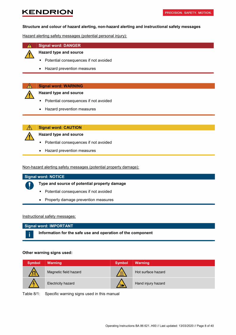
Structure and colour of hazard alerting, non-hazard alerting and instructional safety messages Hazard alerting safety messages (potential personal injury):
Signal word: DANGER
Hazard type and source
Potential consequences if not avoided
• Hazard prevention measures
Signal word: WARNING
Hazard type and source
Potential consequences if not avoided
• Hazard prevention measures
Signal word: CAUTION
Hazard type and source
Potential consequences if not avoided
• Hazard prevention measures
Non-hazard alerting safety messages (potential property damage): Signal word: NOTICE
Type and source of potential property damage
Potential consequences if not avoided
• Property damage prevention measures
Instructional safety messages: Signal word: IMPORTANT
Information for the safe use and operation of the component
Other warning signs used:
Symbol Warning Symbol Warning
Magnetic field hazard
Hot surface hazard
Electricity hazard
Hand injury hazard
Table 8/1: Specific warning signs used in this manual

Operating Instructions BA 86 621..H00 // Last updated: 13/03/2020 // Page 9 of 40
2.2 Intended use
The components described in these operating instructions are intended to be incorporated into machines, in particular electric motors, for use in industrial installations. IMPORTANT
The components must be used in accordance with the operating requirements detailed in these operating instructions. The specified rated power limits must not be exceeded. Operation in potentially explosive or firedamp atmospheres is not allowed.
2.3 General safety information
Built-in brakes feature hazardous live components and rotating parts and may exhibit hot surfaces. Any work associated with the transport, connection, putting into service and periodical maintenance of the brakes must be carried out by authorised and suitably qualified specialist personnel in accordance with EN 50110-1, EN 50110-2, IEC 60364-1. Failure to observe safety, operating and maintenance instructions may cause serious personal injury and property damage. Whenever special measures are required in accordance with the instructions contained herein, such measures should be agreed with the brake manufacturer before setting up the machinery into which the brake is to be incorporated. Should any queries arise with respect to torques, torque variations, installation positions, wear, wear reserve, switching work, break-in conditions, release range, ambient conditions and the like, please contact the manufacturer and ask for clarification before using the brake. Retrofitting or modification work to be carried out on the brake is subject to the approval from Kendrion (Villingen). Accident prevention regulations applying to the specific field of application of the brake must be strictly observed. IMPORTANT
The components described in this manual are not designed for use as “safety brakes”. This means that negative effects on the brake torque (e.g. brake torque variations, reduced brake torque constancy) arising from adverse ambient conditions that are beyond the user's control (e.g. higher ambient temperatures or humidity, contaminated ambient air etc.) cannot be ruled out. In such cases the system user is required to ensure that the component is subjected to a break-in process at regular intervals to achieve the full braking effect. The break-in process parameters specified in Table 38/2 apply.
2.3.1 Set-up
Requirements in terms of the permissible number of switching operations per hour and the maximum switching work per switching operation specified in the technical specifications (see Table 37/1) must be strictly observed during the set-up of machinery and installations (jog mode). Failure to observe these instructions may irreversibly diminish the braking effect and cause malfunctions. The rated operating conditions are those specified by DIN VDE 0580. The protection rating conforms to EN 60529. In case of deviations, special measures must be taken after prior consultation with the brake manufacturer. Bear in mind that the brake armature (4) and the surfaces of the inner ring (3) or outer ring (2) involved in the friction process may freeze if ambient temperatures fall below -5°C or if the brake remains unpowered for prolonged periods of time. In this case, special precautions must be taken after consultation with the brake manufacturer. 2.3.2 Putting into service
Do not use or operate the components if: • power supply cables/wires or connections are damaged. • the field coil sheath is damaged. • other defects are suspected.

Operating Instructions BA 86 621..H00 // Last updated: 13/03/2020 // Page 10 of 40
DANGER
Electricity hazards from incorrect electrical connection of the component!
Fatal electric shock hazard.
• All work must be performed by qualified specialist personnel only. Check that no voltage is present before connecting the component to the power supply. The specifications on the rating plate and the information provided in the circuit diagram in the terminal box of the machine (e.g. motor) or in the operating instructions must be strictly observed.
2.3.3 Installation
The voltage level and voltage type specified on the rating plate (9) must be strictly observed when connecting the components described in these operating instructions. Sufficient heat dissipation must be ensured when the brake is fitted to or incorporated into machinery. Adequate precautions must be taken to avoid overvoltage during turn-off or voltage peaks. The magnetic field of the brake may cause interference outside the brake or even feedback to the brake in case of adverse installation conditions. Should you have queries concerning mounting and fitting conditions, please contact the brake manufacturer and ask for clarification. Adequate safety measures (to DIN 31000 / DIN VDE 0100-420) must be taken by the brake user to avoid hazards to persons and animals or property damage caused by: • direct or indirect effects of electromagnetic fields, • heated components, • moving parts. 2.3.4 Operation and use
Ensure that live components such as plug contacts, the field coil and similar parts are not exposed to water. The brake cable connections must not be crushed, squeezed or exposed to mechanical loads. Make absolutely sure that the friction surfaces of the friction components are not contaminated with grease, oil or other fluids to avoid substantial torque reduction. Bear in mind that the original torque cannot be restored even if the friction surfaces are cleaned after contact with fluids. The gradual brake wear (only with dynamic brakes or holding brakes with emergency stop function; see Table 37/1 – Technical specifications) must be taken into consideration in the set-up of the machinery or installation. Due to the diverse ambient conditions in which the brakes may be used, always check that the brake is in perfect working order before start-up. Torque reductions may occur if the brake is used for applications where only minimum friction work is required. In such cases, the user should ensure that the brake occasionally performs sufficient friction work. The components are factory-treated with a corrosion inhibitor to provide basic corrosion protection during storage and operation in dry environments (no condensation). IMPORTANT
The maximum air gap smax (see Table 37/1 – Technical specifications) must not be exceeded throughout the entire brake service life. Please refer to Section 5 (Maintenance, repair, replacement) for details. The M4 transmissible torque (see Table 37/1 – Technical specifications) is not fully reached until the break-in process has been completed (burnishing of friction surfaces). The break-in parameters are specified in Table 38/2. The brake torque may drop if the brake has been stored for a prolonged period of time. Torque reductions may also occur during the brake service life as a result of adverse factors in the brake environment (see Section 2.3) or if the brake is only used as holding brake. In this case, the brake user should ensure that a break-in process as specified in Table 38/2 is conducted at regular intervals.
Operating Instructions BA 86 621..H00 // Last updated: 13/03/2020 // Page 11 of 40
IMPORTANT
The brake, and more specifically the armature, is not subject to specific requirements in terms of the balance quality grade to DIN ISO 21940-11. Consequently, the required balance quality must be agreed between the manufacturer and customer in each individual case.
NOTICE
Risk of damage to the field coil (1.2) in case of brake operation beyond the permissible limits!
Release of the permanent-magnet single-face brake may no longer be possible. Potential malfunction of the machine (e.g. motor).
• During brake operation, ensure that the coil temperature does not rise above the permissible limit temperature applicable to the insulating materials of the specified insulation class (see Table 37/1 – Technical specifications). Fast cooling of the field coil with scavenging air is not allowed. Ensure that the relative humidity and ambient temperature remain within the permissible range (see rated operating conditions in Table 37/2).
• A maximum 6g continual shock load over a service life of 20,000 operating hours is permitted for the permanent-magnet single-face brake. The armature connection, hub connection and power supply connections are subject to the user's approval. Vibration loads with a maximum excursion of 1.5 mm and a maximum 6g acceleration are permitted within a frequency band of 10 to 2000 Hz.
DANGER
Electromagnetic field hazards during brake operation!
Indirect effects of electromagnetic fields may cause disturbances and failures of cardiac pacemakers and other implants.
Serious or even fatal injury hazard.
• Keep at a safe distance from the component during operation.
2.3.5 Maintenance, repair, replacement
Service, maintenance, repair or replacement of the components must only be carried out by qualified specialist personnel in accordance with EN 50110-1, EN 50110-2, IEC 60364-1. Failure to perform repairs according to requirements may cause serious personal injury or property damage. Make sure that the components are unpowered when carrying out maintenance work.
Operating Instructions BA 86 621..H00 // Last updated: 13/03/2020 // Page 12 of 40
3. Product description 3.1 Operating principle
The permanent-magnet single-face brake is designed to operate dry. The force generated by a permanent magnetic field is utilised to produce the braking effect. To neutralise the braking action, the magnetic flux of the permanent magnets is offset by an alternate electromagnetic field (electromagnetically released system). The zero-backlash connection between the armature (4) and flange hub (5) ensures zero-backlash transmission of the brake torque to the machine shaft (e.g. motor shaft) (12) and reliable release of the permanent-magnet single-face brake with zero residual torque. Owing to these features, permanent-magnet single-face brakes are ideal for servo motor applications. When DC voltage is applied to the field coil (1.2) of the permanent-magnet single-face brake, the alternate electromagnetic field offsets the force exerted on the armature (4) by the permanent magnetic field and the brake is released. Except for the minimal force exerted by the segment springs (7), the machine shaft (e.g. motor shaft) (12) to be braked is not exposed to any other axial force. The permanent magnetic field attracts the armature (4) and pulls it in frictional contact with the outer ring (2) or inner ring (3). The resulting friction force generates the brake torque. 3.2 Design of brake version with armature type 200
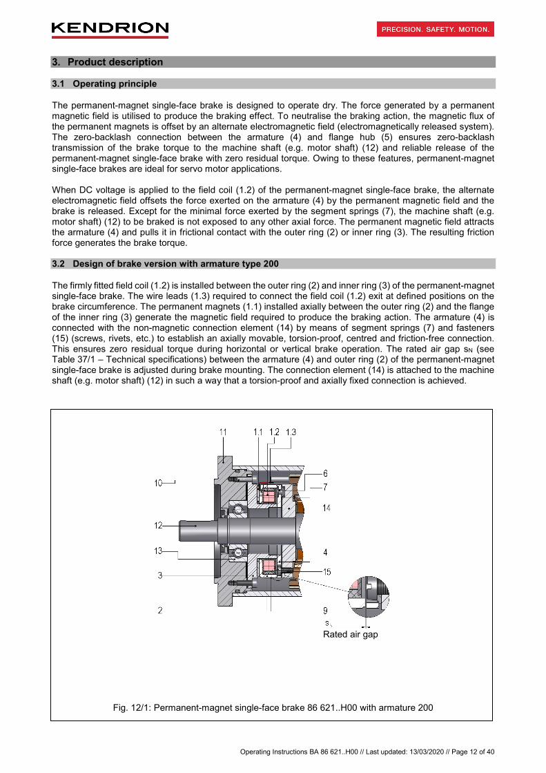
The firmly fitted field coil (1.2) is installed between the outer ring (2) and inner ring (3) of the permanent-magnet single-face brake. The wire leads (1.3) required to connect the field coil (1.2) exit at defined positions on the brake circumference. The permanent magnets (1.1) installed axially between the outer ring (2) and the flange of the inner ring (3) generate the magnetic field required to produce the braking action. The armature (4) is connected with the non-magnetic connection element (14) by means of segment springs (7) and fasteners (15) (screws, rivets, etc.) to establish an axially movable, torsion-proof, centred and friction-free connection. This ensures zero residual torque during horizontal or vertical brake operation. The rated air gap sN (see Table 37/1 – Technical specifications) between the armature (4) and outer ring (2) of the permanent-magnet single-face brake is adjusted during brake mounting. The connection element (14) is attached to the machine shaft (e.g. motor shaft) (12) in such a way that a torsion-proof and axially fixed connection is achieved.
Fig. 12/1: Permanent-magnet single-face brake 86 621..H00 with armature 200
Rated air gap
Operating Instructions BA 86 621..H00 // Last updated: 13/03/2020 // Page 13 of 40
List of reference numerals in Fig. 12/1: 1.1 Permanent magnet 9 Rating plate 1.2 Field coil 10 Mounting screws 1.3 Wire leads 11 Mounting surface (e.g. motor end shield) 2 Outer ring 12 Machine shaft (e.g. motor shaft) 3 Inner ring 13 Bearing (e.g. deep groove ball bearing of motor) 4 Armature 14 Connection element (non-magnetic) 6 Rivet fastener 15 Mounting screw for connection element (14) 7 Segment spring
Table 13/1: List of reference numerals for permanent-magnet single-face brake 3.3 Design of brake version with armature type 300
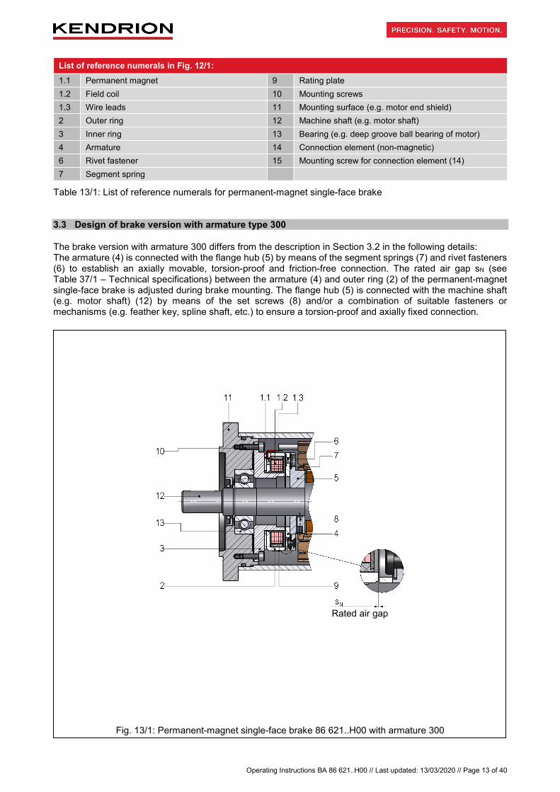
The brake version with armature 300 differs from the description in Section 3.2 in the following details: The armature (4) is connected with the flange hub (5) by means of the segment springs (7) and rivet fasteners (6) to establish an axially movable, torsion-proof and friction-free connection. The rated air gap sN (see Table 37/1 – Technical specifications) between the armature (4) and outer ring (2) of the permanent-magnet single-face brake is adjusted during brake mounting. The flange hub (5) is connected with the machine shaft (e.g. motor shaft) (12) by means of the set screws (8) and/or a combination of suitable fasteners or mechanisms (e.g. feather key, spline shaft, etc.) to ensure a torsion-proof and axially fixed connection.
Fig. 13/1: Permanent-magnet single-face brake 86 621..H00 with armature 300
Rated air gap

Operating Instructions BA 86 621..H00 // Last updated: 13/03/2020 // Page 14 of 40
List of reference numerals in
1.1 Permanent magnet 7 Segment spring 1.2 Field coil 8 Set screw 1.3 Wire leads 9 Rating plate 2 Outer ring 10 Mounting screws 3 Inner ring 11 Mounting surface (e.g. motor end shield) 4 Armature 12 Machine shaft (e.g. motor shaft) 5 Flange hub 13 Bearing (e.g. deep groove ball bearing of motor) 6 Rivet fastener
Table 14/1: List of reference numerals for permanent-magnet single-face brake 3.4 Design of brake version with armature type 400
The brake version with armature 400 differs from the description in Section 3.2 in the following details: The armature (4) is connected with the flange hub (5) by means of the segment springs (7) and rivet fasteners (6) to establish an axially movable, torsion-proof and friction-free connection. The rated air gap sN (see Table 37/1 – Technical specifications) between the armature (4) and outer ring (2) of the permanent-magnet single-face brake is automatically adjusted during brake mounting and results from the geometrical dimensions and tolerances of the relevant components (flange hub (5), machine shaft (e.g. motor shaft) (12), ball bearing (13), end shield (11) and coil system of brake). The flange hub (5) is connected with the machine shaft (e.g. motor shaft) (12) by means of the set screws (8) and/or a combination of suitable fasteners or mechanisms (e.g. feather key, spline shaft, etc.) to ensure a torsion-proof and axially fixed connection. IMPORTANT
The distance L (see Fig. 14/1) between the outer ring of the ball bearing (13) (limit stop for inner ring (3) of brake) and the stop shoulder of the machine shaft (e.g. motor shaft) (12) (limit stop for flange hub (5)) must be dimensioned in such a way that the required rated air gap sN (see Table 37/1 – Technical specifications) is automatically adjusted when the brake is mounted to the machine (e.g. motor).
Fig. 14/1: Permanent-magnet single-face brake 86 621..H00 with armature 400
Rated air gap
Operating Instructions BA 86 621..H00 // Last updated: 13/03/2020 // Page 15 of 40
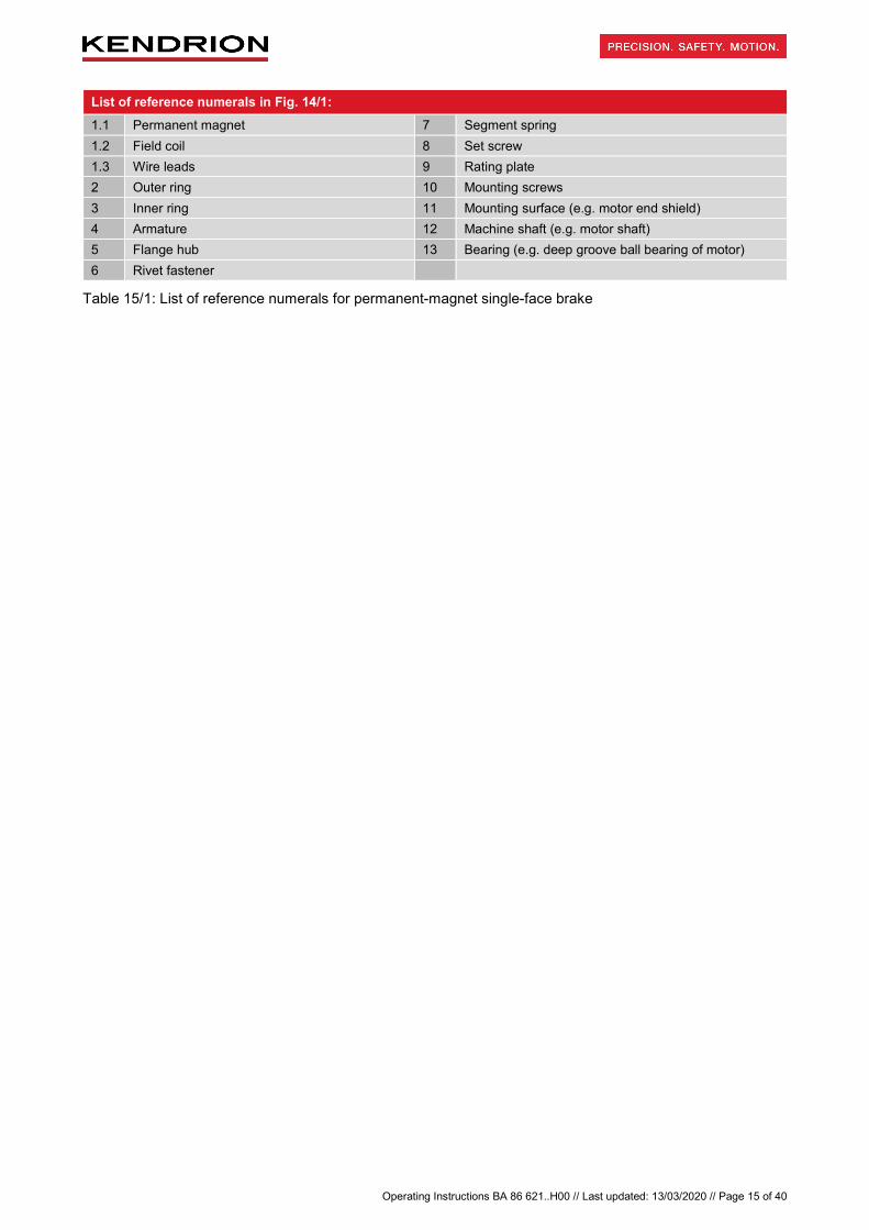
List of reference numerals in Fig. 14/1: 1.1 Permanent magnet 7 Segment spring 1.2 Field coil 8 Set screw 1.3 Wire leads 9 Rating plate 2 Outer ring 10 Mounting screws 3 Inner ring 11 Mounting surface (e.g. motor end shield) 4 Armature 12 Machine shaft (e.g. motor shaft) 5 Flange hub 13 Bearing (e.g. deep groove ball bearing of motor) 6 Rivet fastener
Table 15/1: List of reference numerals for permanent-magnet single-face brake

Operating Instructions BA 86 621..H00 // Last updated: 13/03/2020 // Page 16 of 40
4. Installation 4.1 Mechanical installation
After having centred the brake field coil with the end shield (11) of the machine (e.g. motor) over the outside diameter d3 of the inner ring (3) (d3 as specified in the PM Line catalogue for 86 621..H00 brakes), the entire assembly must be screwed to the motor end shield (11) from the rear side by means of the mounting screws (10) (e.g. socket head cap screws to ISO 4762; property class 8.8). IMPORTANT
Tighten the mounting screws (10) evenly in several steps. Ensure that the mounting screws (10) are securely locked. This can be achieved by using microencapsulated screws that comply with the requirements of DIN 267-27. The MA tightening torque (see Table 17/1) specified for the mounting screws (10) must be strictly observed. Use a torque wrench to tighten the screws.
Mounting armature types 200, 300 and 400: IMPORTANT
The machine shaft (e.g. motor shaft) (12) and the end shield (11) must be dimensioned in such a way that the rated air gap sN (see Table 37/1 – Technical specifications) is automatically adjusted when the end shield (11) and coil system of the permanent-magnet single-face brake are installed (brake mounting on preloaded fixed bearing side). If necessary, use shim rings to adjust the air gap. Install the shim rings between the contact surface of the machine shaft (e.g. motor shaft) (12) and the flat face of the flange hub (5) (or customer-specific connection element (14) when armature type 200 is used). Kendrion (Villingen) recommends that the machine shaft (e.g. motor shaft) (12) should be made of E335 steel to DIN EN 10025 (Rm = 570-710 N/mm² => 180-220 HV). If the flange hub (5) (armature types 300 and 400) is connected with the machine shaft (e.g. motor shaft) (12), Kendrion (Villingen) recommends that the shaft should have a surface roughness of Rzmax = 4 µm and an s6 tolerance zone in the flange hub bore.
Armature type 200: Connect the armature (4) with the customer-specific non-magnetic connection element (14) using mounting screws (15) according to ISO 14583, property class 8.8, for M2 to M5 threads, or according to ISO 7380-1, property class 8.8, for M6 to M8 threads. Ensure that the armature type 200 is firmly connected with the customer-specific connection element (14) by means of segment springs (7) to achieve a torsion-proof, centred, friction-free and axially movable connection. IMPORTANT
Tighten the mounting screws (15) evenly in several steps. Ensure that the mounting screws (15) are securely locked. This can be achieved by using microencapsulated screws that comply with the requirements of DIN 267-27. The MA tightening torque (see Table 17/1) specified for the mounting screws (15) must be strictly observed. Use a torque wrench to tighten the screws. The design of the customer-specific non-magnetic connection element (14) required to mount the armature type 200 is detailed in the PM Line catalogue in the brake type 86 621..H00 section. The connection element (14) must be mounted to the machine shaft (e.g. motor shaft) (12) by the brake user. Particular care is required to ensure that the brake torque is reliably transmitted to the machine shaft (e.g. motor shaft) (12).

Operating Instructions BA 86 621..H00 // Last updated: 13/03/2020 // Page 17 of 40
Armature types 300 and 400: Slip the flange hub (5) with mounted armature (4) on the machine shaft (e.g. motor shaft) (12) and secure it axially by means of the set screws (8) to ISO 4029. Brake size 04 06 07 09 11 14 16
Mounting screw (10) thread M3 M4 M5 M6 M6 M6 M8
MA tightening torque [Nm] for mounting screws (10) 1.2 3 5 9 9 9 24
Set screw (8) thread M3 M3 M4 M5 M6 M8 M8
MA tightening torque [Nm] for set screws (8) 0.9 0.9 2 4 7 16 16
Mounting screw (15) thread M3 M3 M4 M5 M6 M8 M8
MA tightening torque [Nm] for mounting screws (15) 0.75 0.75 1.8 3.5 7.2 17 17
Table 17/1: Threads of mounting screws (10 & 15) and set screws (8); MA tightening torques for mounting screws (10 & 15) and set screws (8); tightening torques tolerance ±10%
WARNING
Hazards from reduced braking effect caused by deformed component parts (inner ring (3), outer ring (2) etc.)!
Uncontrolled movements of the machine shaft (e.g. motor shaft) (12) may cause injury hazards if persons are present within the confines and/or working range of the installation.
Uncontrolled extremely fast movements of the machine shaft (e.g. motor shaft) (12) may cause death if persons are present within the confines and/or working range of the installation.
• The MA tightening torques specified for the mounting screws (10 & 15) and set screws (8) (see Table 17/1) must be strictly observed. Tighten the mounting screws (10 & 15) and set screws (8) evenly in two separate steps. In the first step, tighten the mounting screws (10 & 15) and the set screws (8) evenly, applying about 10% of the specified MA tightening torque (see Table 17/1). In the second step, tighten the mounting screws (10 & 15) and the set screws (8) evenly, applying the total MA tightening torque (see Table 17/1). Avoid any deformation of the outer ring (2) and inner ring (3) during brake mounting (e.g. caused by excessive tightening of the mounting screws (10)).
• Ensure that the brake is mounted correctly and with maximum care.

Operating Instructions BA 86 621..H00 // Last updated: 13/03/2020 // Page 18 of 40
WARNING
Hazards from brake failure caused by incorrect design of the machine shaft (e.g. motor shaft) (12)!
Uncontrolled movements of the machine shaft (e.g. motor shaft) (12) may cause injury hazards if persons are present within the confines and/or working range of the installation.
Uncontrolled extremely fast movements of the machine shaft (e.g. motor shaft) (12) may cause death if persons are present within the confines and/or working range of the installation.
• When a pressed-on flange hub (5) and secured set screws (8) are used (with armature types 300 and 400), ensure that the tolerance of the shaft (12) and the type of set screw (8) used (e.g. set screws with hexagon socket to DIN 4029; property class 45H) are suitable to achieve reliable transmission of the generated brake torques over the entire brake service life.
• The set screws (8) must be provided with a thread locker (e.g. using microencapsulated set screws (8)) to DIN 267-27. Ensure that the pole faces are kept free of adhesive residues or similar substances at all times, especially during brake operation at the maximum permissible speed nmax (see Table 37/1). Check that the set screws (8) do not project from the thread bores of the flange hub (5). Ensure that the effective thread length of the set screws (8) enables reliable transmission of the MA tightening torque (see Table 17/1) on a long-term basis. If necessary, the machine shaft (e.g. motor shaft) (12) must be adjusted in such a way that any projection of the set screws (8) is avoided (e.g. necking of the shaft (12)).
• Ensure that the brake is mounted correctly and with maximum care.
NOTICE
Risk of damage to the brake or mounting screws (10 & 15) and set screws (8) if the MA tightening torque is too high or too low!
Potential malfunction of the permanent-magnet single-face brake. Potential malfunction of the machine (e.g. motor). Potential breakage or loosening of the mounting screws (10 & 15).
• The MA tightening torques specified for the mounting screws (10 & 15) and set screws (8) (see Table 17/1) must be strictly observed. Tighten the mounting screws (10 & 15) and set screws (8) evenly in several steps. Check that the thread reach of the mounting screws (10) is as specified in Table 17/1.
• Avoid any deformation of the outer ring (2) and inner ring (3) during brake mounting (e.g. caused by excessive tightening the mounting screws (10)).
NOTICE
Risk of damage to the wire leads (1.3) and machine shaft (e.g. motor shaft) (12) in case of incorrect brake mounting!
Putting into service of the permanent-magnet single-face brake and machine (e.g. motor) may not be possible.
• During machine installation, the wire leads (1.3) of the field coil (1.2) must be connected as specified by the machine manufacturer. Avoid damage to the wire leads (1.3), e.g. by kinking the lead insulation.

Operating Instructions BA 86 621..H00 // Last updated: 13/03/2020 // Page 19 of 40
NOTICE
Risk of brake damage caused by incorrect dimensions of the set screws (8) and mounting surface (11)!
Potential malfunction of the permanent-magnet single-face brake. Potential malfunction of the machine (e.g. motor). Potential breakage or loosening of the mounting screws (10 & 15).
• Check that the set screws (8) are not too long to prevent contact with the inner ring (3) during brake operation. The mounting surface (11) (e.g. motor end shield) must be dimensioned in such a way that the screw connection is not affected by setting effects or similar phenomena.
IMPORTANT
The axial runout of the pole faces of the brake relative to the machine shaft (e.g. motor shaft) (12) must not exceed 0.05 mm after the screws have been tightened.
IMPORTANT
Magnetic interference fields may affect reliable brake operation. Consequently, the brake should always be installed outside the reach of magnetic interference fields.
IMPORTANT
During brake installation, all parts must be axially secured and axial bearing play must be eliminated. The inner ring of the bearing (13) (e.g. motor bearing) must be kept preloaded by using suitable mechanical parts. Make sure that lubricants and similar substances cannot seep from the bearing (13) (e.g. motor bearing) into the brake. (Sealed bearings can be used to prevent lubricant leaks.) The assembled brake components, especially the surfaces involved in the friction process, must be free of grease and oil. During installation of the flange hub (5) with armature (4), deformation of the segment springs (7) must be avoided. The air gap must not be larger or smaller than the rated air gap sN (see Table 37/1). An opening can be provided in the machine housing (e.g. motor housing) to insert a feeler gauge (see Section 9) in order to measure the air gap ‘s’ between the outer ring (2) and armature (4) (see Section 5.1 – Maintenance).

Operating Instructions BA 86 621..H00 // Last updated: 13/03/2020 // Page 20 of 40
4.2 Electrical connection and operation
The permanent-magnet single-face brake must be connected directly to a smoothed DC power source, connecting the wire leads (1.3) to the power supply with the correct polarity (see Table 20/1). The power supply specifications on the rating plate (9) must be observed. Connection to an AC power source is only possible by means of bridge rectifiers. A special Kendrion rectifier type (see Table 20/2 (list not exhaustive)) can be provided for this purpose, if required.
Wire leads Polarity
Blue wire lead (1.3) of brake -
Red wire lead (1.3) of brake +
Table 20/1: Polarity of wire leads IMPORTANT
The correct polarity of the wire leads is crucial to ensure reliable operation of the permanent-magnet single-face brake (see Table 20/1). During operation, any contact of the wire leads (1.3) with the rotating armature (4) or other rotating parts must be avoided. Shorten the wire leads, if necessary. Depending on the brake size and torque, voltage ripple due to intermittent power supply may cause humming or incorrect operation. Reliable operation must be ensured by the user or system manufacturer by providing suitable electrical controls.
Rectifier series Rectifier type Rated input voltage range
U1 (±10%) [VAC] (40 – 60 Hz)
Output voltage U2 [VDC]
Max. output current I [ADC]
32 07.23B.0 Bridge 0 – 400 (±10%) U1 · 0.890 2.0
32 07.03B0. Bridge 0 – 500 (±10%) U1 · 0.890 2.0
The relevant rectifier specification sheets must be observed!
Table 20/2: Recommended rectifiers for single-phase AC voltage supply

Operating Instructions BA 86 621..H00 // Last updated: 13/03/2020 // Page 21 of 40
4.2.1 DC power supply
The figure to the right shows the voltage curve after the field coil (1.2) has been de-energised without protective circuit (torque curve and times t11 and t1 as specified in DIN VDE 0580). NOTICE
Risk of damage to or destruction of the brake field coil (1.2) from overvoltage!
Release of the permanent-magnet single-face brake may no longer be possible.
Potential malfunction of the machine (e.g. motor).
• The peak voltage UVmax during turn-off without protective circuit may reach several thousand volts in the millisecond region. This may cause irreversible damage to the field coil (1.2), switching contacts and electronic components. Sparking will occur on the switch during turn-off. Consequently, a protective circuit must be provided to reduce the current during turn-off and to limit the voltage. The maximum permissible overvoltage during turn-off is 1500 V.
NOTICE
Risk of damage to or destruction of electronic components from overvoltage!
Release of the permanent-magnet single-face brake may no longer be possible. Potential malfunction of the machine (e.g. motor).
• The maximum permissible overvoltage during turn-off is 1500 V. If Kendrion rectifiers are used (see Table 20/2), the protective circuit required for the built-in electronic components and field coil (1.2) is included in the rectifier. This does not apply to the external contacts required for DC side switching as there would be no galvanic isolation of the external contact. Sensitive electronic components (e.g. logical components) may also be damaged by the lower voltage.
4.2.2 AC power supply
Direct brake connection to an AC power source is only possible if a bridge rectifier is used. The coupling times vary (DIN VDE 0580) depending on the switching type (DC side switching or AC side switching). Bridge rectification: Bridge rectifiers provide voltage with minimum residual ripple. This means that brake humming can be avoided even if small size brakes are used. In case of bridge rectification, the U2 coil voltage is lower by factor 0.89 than the rectifier input voltage U1. AC side switching: The easiest wiring method is to connect the rectifier in parallel with the brake in the terminal box of the machine (e.g. motor). It must be considered, however, that the motor may act as a generator after AC voltage has been removed and thus extend the coupling time significantly (by factor 5 or over). The disconnection times remain unchanged.
t
t
M
U
0,9 x M 2
B U
U Vmax
t t
11 1
1 M
UB operating voltage (coil voltage) UVmax turn-off voltage

Operating Instructions BA 86 621..H00 // Last updated: 13/03/2020 // Page 22 of 40
DC side switching: In case of DC side brake switching, an auxiliary contact is provided on the motor contactor, for example, to interrupt the power supply on the DC side (brake side). When the permanent-magnet single-face brake is operated in this manner, bear in mind that the significant reduction of the electric time constant causes the brake to close quickly and the switching noise to increase (see Section 7 – Emissions). NOTICE
Risk of damage to or destruction of electronic components and the brake field coil (1.2) if protection measures are insufficient or inadequate!
Release of the permanent-magnet single-face brake may no longer be possible. Potential malfunction of the machine (e.g. motor).
• In case of DC side switching, the brake must be provided with a protective circuit to avoid overvoltage. Additional protective elements (e.g. varistors, spark arresters, etc.) must be installed to avoid damage such as burns or fusing of contacts.
2 2
1
1
2
3
2
Bridge rectifier
Field coil (1.2) Bridge rectifier with DC side turn-off
1
3
- ~ ~ +
M 3~
L1 L2 L3
- ~ ~ +
M 3~
L1 L2 L3
- ~ ~ +
M 3~
L1 L2 L3
AC side switching AC side switching (connected in parallel with the machine (e.g. motor))
DC side switching
Operating Instructions BA 86 621..H00 // Last updated: 13/03/2020 // Page 23 of 40
The following checks must be carried out when connecting the brake: • Check that the connecting cables are suitable for the intended use and for the voltage and amperage of
the brake.
• Check that the connecting cables are secured with screws, clamps or other suitable fixtures to avoid interruptions in the power supply.
• Check that the connecting cables are long enough for the intended use and that suitable torsion, strain and shear relief features as well as bending protections are provided.
• Check that the PE conductor (only for protection class I) is connected to the earthing point.
• Check that no foreign matter, dirt or humidity is trapped inside the terminal box.
• Check that unused cable entries and the terminal box are suitably sealed to ensure compliance with the protection class requirements to EN 60529.
DANGER
Electricity hazards from incorrect electrical connection of the component!
Fatal electric shock hazard.
• All work must be performed by qualified specialist personnel only. Check that no voltage is present before connecting the component to the power supply. The specifications on the rating plate and the information provided in the circuit diagram in the terminal box of the machine (e.g. motor) or in the operating instructions must be strictly observed.
NOTICE
Risk of damage to the field coil (1.2) from incorrect electrical connection of the component!
Release of the permanent-magnet single-face brake may no longer be possible. Putting into service of the permanent-magnet single-face brake and machine (e.g. motor) may
not be possible.
• The brake is a DC operated system. The permissible permanent voltage variations on the power source of the electromagnetic brake are specified in Table 37/2.

Operating Instructions BA 86 621..H00 // Last updated: 13/03/2020 // Page 24 of 40
4.3 Electromagnetic compatibility
As required by the German Electromagnetic Compatibility Act (EMVG), electromagnetic compatibility is essential to ensure immunity to external electromagnetic fields and conducted interference. Furthermore, the emission of electromagnetic fields and line-conducted interference during brake operation must be minimised. Since the brake features depend on the circuitry and operation, a declaration of conformity with the applicable EMC standard can only be furnished for the wiring type, but not for a specific brake. The permanent-magnet single-face brakes in the 86 621..H00 series are designed for industrial applications to which the following EMC standards apply: Generic Immunity Standard EN 61000-6-2 and Generic Emission Standard EN 61000-6-3 / EN 61000-6-4. Other applications may be subject to different generic standards which must be considered by the manufacturer of the installation. The requirements in terms of electromagnetic compatibility of devices and components are determined by basic standards derived from the generic standards. Wiring recommendations will be provided in the following sections to ensure compliance with the individual basic standards that are relevant for industrial use and other applications. Please refer to the specification sheets for additional information on electromagnetic compatibility, especially with respect to the recommended electronic rectifiers specified in Section 4.2. Immunity according to EN 61000-4: EN 61000-4-2 Electrostatic discharge: The permanent-magnet single-face brakes in the 86 621..H00 series comply at least with severity level 3 without requiring additional measures. The recommended rectifiers specified in Section 4.2 conform to severity level 3 without additional measures. EN 61000-4-3 Electromagnetic fields: The brakes comply at least with severity level 3 without requiring additional measures. The recommended rectifiers conform to severity level 3 without additional measures. EN 61000-4-4 Fast transients (burst): The brakes comply at least with severity level 3 without requiring additional measures. The recommended rectifiers conform to severity level 3. EN 61000-4-5 Surge: The brakes comply at least with severity level 3 without requiring additional measures. The recommended rectifiers conform to severity level 3. EN 61000-4-9 Pulse magnetic fields, EN 61000-4-10 Damped oscillatory magnetic fields: Since the operating magnetic fields of the electromagnetic brakes are stronger many times over than interference fields, the brake function will remain unaffected. The brakes comply at least with severity level 4. The recommended rectifiers conform at least to severity level 3. EN 61000-4-11 Voltage dips, short interruptions, and short supply voltage variations: a) Voltage interruptions:
Brakes that comply with the requirements of DIN VDE 0580 are de-energised after the specified switching times at the latest. The switching time depends on the control and mains conditions (e.g. generator effect of running down motors). Voltage interruptions of shorter duration than the response delay specified by DIN VDE 0580 will not cause any malfunctions. The user must ensure that any consequential damage is avoided (e.g. motor start-up before the brake has been released caused by phase failure in the case of two-phase energised motors or by the slipping of an electromagnetically engaged system due to torque drop). The functional reliability of the electromagnetic component and its electronic accessories remains unaffected if the aforementioned consequential damage is avoided.
b) Voltage dips and short supply voltage variations:
Electromagnetically released systems: Voltage dips and supply voltage variations to below 60% of the rated voltage and lasting longer than the response delay specified by DIN VDE 0580 may cause the brake to be de-energised temporarily. Consequential damage as described under a) above must be avoided by the user by taking adequate precautions. Electromagnetically engaged systems: Voltage dips and supply voltage variations to below the minimum tolerance threshold will cause torque reductions. The user is required to take adequate precautions to avoid consequential damage.

Operating Instructions BA 86 621..H00 // Last updated: 13/03/2020 // Page 25 of 40
Radio interference suppression in accordance with EN 55011: The brakes and the recommended electronic rectifiers are classified as Group 1 equipment in accordance with EN 55011. As far as the emissions from this equipment are concerned, one distinguishes between field guided radiated interference and line-conducted interference. a) Radiated interference:
When operated with DC voltage or rectified 50/60 Hz AC voltage, all brakes comply with the limit values applicable to Class B equipment.
b) Conducted interference: When connected to a DC power source, the electromagnetic brakes meet the limit values applicable to Class A equipment. If the brakes are connected to a 50/60 Hz AC power source and equipped with electronic rectifiers or other electronic controls, interference suppression measures as shown in Fig. 25/1 must be taken to ensure compliance with the limit values applicable to Class A equipment. Interference suppression capacitors should be used which must be dimensioned to suit the connection data of the electromagnetic components and the specific mains conditions. The recommended rectifiers specified in Section 4.2 are CE mark certified in accordance with the EMC Directive. They have built-in interference suppression components and comply at least with the requirements of EN 55011 for Class A equipment, unless otherwise specified in the specification sheet. When brakes are used with the specified rectifiers, the recommended values listed in Table 25/1 should be observed. Interference suppression components should be installed as close as possible to the consumer. Interference caused during switching operations of the electromagnetic component is generally attributable to the inductive load. Where necessary, assemblies designed to limit the turn-off voltage (e.g. anti-parallel diode) or voltage limiting components (e.g. varistors, suppressor diodes, resistance diodes and the like) can be installed. However, such components will inevitably change the switching times of the brake and increase the generated noise level. The rectifiers specified in Section 4.2 are equipped with free-wheel diodes and/or varistors to limit the disconnection voltage. In case of DC side switching, a varistor rated for the type-specific maximum operating voltage and connected in parallel with the field coil (1.2) limits the peak voltage to the values specified in Table 26/1.
If the brake is used in connection with other electronic accessories, the user is responsible to ensure compliance with EMC requirements. Compliance with applicable standards concerning the design and operation of components, sub-assemblies or equipment employed shall not relieve the user and manufacturer of the installation from their obligation to furnish proof of conformity of the installation with such standards.
Rectifier series Rated input voltage range U1 (±10%) [VAC] (40 – 60 Hz)
Max. output current I2 [ADC]
Capacitor C / U [nF / VAC]
Bridge rectifier 32 07.23B.0 up to 400 (±10%) up to 2.0 No capacitor required
Bridge rectifier 32 07.03B0.
up to 230 (±10%) up to 500 (±10%)
up to 2.0 up to 2.0
47 / 250~ 100 / 500~
Table 25/1: Recommended measures to comply with the limit values for class A equipment according to EN 55011
Fig. 25/1
R
C
L
U

Operating Instructions BA 86 621..H00 // Last updated: 13/03/2020 // Page 26 of 40
Max. rectifier operating voltage [VAC]
Recommended turn-off voltage in case of DC side switching
250 700
440 1200
550 1500
Table 26/1: Recommended turn-off voltage in case of DC side switching for rectifiers specified in Table 20/2 4.4 Putting into service
Check compliance with the specifications provided on the rating plate (9) with respect to the mounting position and protection class. After the brake has been connected to the power source, a functional test must be performed to check that the armature assembly (armature types 200, 300, 400) is not blocked. For this purpose, turn the shaft (12) while the brake is energised and the machine (e.g. motor) is unpowered. After completion of mounting, all necessary covers and guards must be installed. At the end of the mounting procedure or whenever necessary (e.g. after a prolonged storage period), a break-in process must be conducted in accordance with the parameters specified in Table 38/2. Specifications on rating plate (order-specific, example brake type 86 62104H00):
Note: The product number of the permanent-magnet brake consists of the type number followed by the
version number, e.g. 86 62104H00-0001.
DANGER
Electricity hazards from incorrect electrical connection of the component!
Fatal electric shock hazard.
• All work must be performed by qualified specialist personnel only. Check that no voltage is present before connecting the component to the power supply. The specifications on the rating plate and the information provided in the circuit diagram in the terminal box of the machine (e.g. motor) or in the operating instructions must be strictly observed.
CAUTION
Hazards from contact with rotating parts (e.g. machine shaft (motor shaft) (12) etc.) during operation of the permanent-magnet single-face brake and/or machine (e.g. motor)!
Physical injury hazard (e.g. chafing, cuts etc.) to hands and limbs.
• Functional testing of the brake must not be performed unless the machine (e.g. motor) has been turned off and secured so that it cannot be turned back on inadvertently or by unauthorised persons. Do not touch rotating parts (e.g. machine shaft (motor shaft) (12) etc.).
1 Type number 2 Version number (4-digit) 3 Offer drawing index 4 Rated voltage 5 Rated current 6 Transmissible torque 7 CE mark 8 Production ID code 9 Manufacturing date (year and month, 3-digit)

Operating Instructions BA 86 621..H00 // Last updated: 13/03/2020 // Page 27 of 40
CAUTION
Hazards from contact with loose parts during operation of the permanent-magnet single-face brake and/or machine (e.g. motor)!
Physical injury hazard (e.g. cuts etc.) to limbs and other parts of the body.
• Before starting the machine (e.g. motor) test run without driven components, the feather key (if used) must be secured in such a way that it cannot be hurled out. The machine shaft (e.g. motor shaft) (12) must not be exposed to load torques. Ensure that the brake is unpowered before restarting the machine.
CAUTION
Hazards from contact with hot parts during operation of the permanent-magnet single-face brake!
Injury hazard (e.g. skin burns) to hands, limbs and other parts of the body.
• Depending on the operating state of the brake, its surface temperature may rise to over 60°C. If necessary, suitable protections and hand guards must be installed to avoid accidental contact with hot surfaces.
• Wear protective gloves, if necessary.
NOTICE
Risk of property damage caused by hot parts during operation of the permanent-magnet single-face brake!
Release of the permanent-magnet single-face brake may no longer be possible. Irreversible damage to heat-sensitive parts (e.g. cables) may occur. Putting into service of the permanent-magnet single-face brake and machine (e.g. motor) may
not be possible.
• The brake surface temperature may rise to over 60°C. Heat-sensitive parts such as conventional cables or electronic components must not be fixed to or be in contact with hot surfaces.
NOTICE
Risk of damage to or destruction of the brake field coil (1.2) if the high-voltage test is not performed correctly!
Release of the permanent-magnet single-face brake may no longer be possible. Putting into service of the permanent-magnet single-face brake and machine (e.g. motor) may
not be possible.
• High-voltage tests performed when mounting the brake in an installation or when putting the brake into service must be carried out in such a way that damage to the built-in electronic accessories is avoided. The limits for high-voltage tests and follow-up tests specified by DIN VDE 0580 must be observed.

Operating Instructions BA 86 621..H00 // Last updated: 13/03/2020 // Page 28 of 40
NOTICE
Risk of damage to the field coil (1.2) from incorrect electrical connection of the component!
Release of the permanent-magnet single-face brake may no longer be possible. Putting into service of the permanent-magnet single-face brake and machine (e.g. motor) may
not be possible.
• Check that the brake has been connected in accordance with the specifications provided on the rating plate before it is put into service. Even short-term operation outside the specified supply voltage limits may cause irreversible damage to the brake or electronic accessories. Such damage may not be apparent immediately. DC side brake switching without protective circuit as described in Section 4.3 will cause damage to electronic rectifiers, electronic accessories, switching contacts and to the field coil (1.2).
IMPORTANT
The opening (release) and braking behaviour of the permanent-magnet single-face brake is affected by magnetic interference fields through magnetically conductive components (e.g. motor shaft). In such cases, the magnetic specifications of the brake must be factory-adjusted to the specific installation conditions.

Operating Instructions BA 86 621..H00 // Last updated: 13/03/2020 // Page 29 of 40
5. Maintenance, repair, replacement 5.1 Maintenance
The permanent-magnet single-face brake does not require any particular maintenance except that the air gap ‘s’ must be measured at regular intervals. When the maximum air gap smax (see Table 37/1 – Technical specifications) between the armature (4) and outer ring (2) of the permanent-magnet single-face brake has been reached, the entire brake must be replaced by a new one. IMPORTANT
An opening can be provided in the machine housing (e.g. motor housing) to insert a feeler gauge (see Section 9) in order to measure the air gap ‘s’ between the outer ring (2) and armature (4).
If the brake is not operated for a long period of time, the surfaces of the inner ring (3) and/or outer ring (2) involved in the friction process may corrode and reduce the brake torque. A short break-in process (see Table 38/2) will restore correct and reliable brake operation.
DANGER
Electricity hazards from incorrect electrical connection or disconnection of the component!
Fatal electric shock hazard.
• All work must be performed by qualified specialist personnel only. Check that no voltage is present before connecting or disconnecting the component to/from the power supply. The specifications on the rating plate and the information provided in the circuit diagram in the terminal box of the machine (e.g. motor) or in the operating instructions must be strictly observed.
WARNING
Hazards from neutralisation of the braking effect in case the maximum permissible air gap smax is exceeded!
Uncontrolled movements of the machine shaft (e.g. motor shaft) (12) may cause injury hazards if persons are present within the confines and/or working range of the installation.
Uncontrolled extremely fast movements of the machine shaft (e.g. motor shaft) (12) may cause death if persons are present within the confines and/or working range of the installation.
• Depending on the brake operating condition, the braking effect (brake function) may be compromised or even lost when the maximum air gap smax (see Table 37/1) is exceeded. Replace the component at the latest when the maximum air gap smax (see Table 37/1) is reached.
WARNING
Hazards from insufficient braking effect in case of contamination of surfaces involved in the friction process of the permanent-magnet single-face brake!
Uncontrolled movements of the machine shaft (e.g. motor shaft) (12) may cause injury hazards if persons are present within the confines and/or working range of the installation.
Uncontrolled extremely fast movements of the machine shaft (e.g. motor shaft) (12) may cause death if persons are present within the confines and/or working range of the installation.
• Ensure that all surfaces involved in the friction process are free of grease and oil. • Ensure that no swelling or glazing of the friction lining (if used) has occurred.

Operating Instructions BA 86 621..H00 // Last updated: 13/03/2020 // Page 30 of 40
CAUTION
Hazards from contact with rotating parts (e.g. machine shaft (motor shaft) (12) etc.) during operation of the permanent-magnet single-face brake and/or machine (e.g. motor)!
Physical injury hazard (e.g. chafing, cuts etc.) to hands and limbs.
• Functional testing of the brake must not be performed unless the machine (e.g. motor) has been turned off and secured so that it cannot be turned back on inadvertently or by unauthorised persons. Do not touch rotating parts (e.g. machine shaft (motor shaft) (12) etc.).
• After completion of inspection and maintenance operations, remove the lock provided to prevent accidental start-up of the machine (e.g. motor).
NOTICE
Risk of brake damage caused by incorrect maintenance!
The correct function and operation of the permanent-magnet single-face brake may be compromised.
Putting into service of the permanent-magnet single-face brake and machine (e.g. motor) may not be possible.
• Any tests conducted to confirm correct function, operational safety and reliability of the permanent-magnet single-face brake must be performed with extreme caution and by qualified specialist personnel only.

Operating Instructions BA 86 621..H00 // Last updated: 13/03/2020 // Page 31 of 40
5.2 Brake repair and replacement in case of failure
If a failure occurs, the entire brake has to be replaced by the manufacturer of the machine (e.g. motor). The brake can only be repaired by the brake manufacturer.
DANGER
Electricity hazards from incorrect electrical connection or disconnection of the component!
Fatal electric shock hazard.
• All work must be performed by qualified specialist personnel only. Check that no voltage is present before connecting or disconnecting the component to/from the power supply. The specifications on the rating plate and the information provided in the circuit diagram in the terminal box of the machine (e.g. motor) or in the operating instructions must be strictly observed.
DANGER
Hazards from incorrect brake replacement!
Uncontrolled movements of the machine shaft (e.g. motor shaft) (12) may cause injury hazards if persons are present within the confines and/or working range of the installation.
Uncontrolled extremely fast movements of the machine shaft (e.g. motor shaft) (12) may cause death if persons are present within the confines and/or working range of the installation.
• The machine (e.g. motor) must be turned off by the manufacturer’s service and/or maintenance personnel before starting to replace the brake. Brake replacement must not be performed unless the machine (e.g. motor) has been turned off and secured so that it cannot be turned back on inadvertently or by unauthorised persons. Do not touch rotating parts (e.g. machine shaft (motor shaft) (12) etc.).
IMPORTANT
Brake replacement must be performed in accordance with the specific maintenance instructions provided by the manufacturer of the machine (e.g. motor). The instructions provided in Section 4 (Installation) of this manual must also be observed.
WARNING
Hazards from neutralisation of the braking effect in case the maximum permissible air gap smax is exceeded!
Uncontrolled movements of the machine shaft (e.g. motor shaft) (12) may cause injury hazards if persons are present within the confines and/or working range of the installation.
Uncontrolled extremely fast movements of the machine shaft (e.g. motor shaft) (12) may cause death if persons are present within the confines and/or working range of the installation.
• Depending on the brake operating condition, the braking effect (brake function) may be compromised or even lost when the maximum air gap smax (see Table 37/1) is exceeded. Replace the component at the latest when the maximum air gap smax (see Table 37/1) is reached.
5.3 Spare parts and accessories
Individual spare parts or accessories are not available for the permanent-magnet single-face brake.

Operating Instructions BA 86 621..H00 // Last updated: 13/03/2020 // Page 32 of 40
6. Condition at delivery, transport and storage The permanent-magnet single-face brake is delivered ready for mounting. Upon receipt of the shipment, the brake must be checked for transit damage before storage. If the brake is not installed immediately upon delivery, it must be stored in a dry, dust-free and vibration-proof place.
Environmental conditions Conditions for storage
to EN IEC 60721-3-1 Conditions for transport
to EN IEC 60721-3-2
Mechanical conditions 1M11 2M4
Climatic conditions 1K21 and 1Z2 2K12
Biological conditions 1B1 2B1
Mechanically active substances 1S11 2S5
Chemically active substances 1C1 2C1
Table 32/1: Environmental conditions for storage and transport as specified in EN IEC 60721-3-1 and EN IEC 60721-3-2
IMPORTANT
The environmental conditions specified in Table 32/1 and in EN IEC 60721-3-2 / EN IEC 60721-3-1 must be considered during transport and storage of the brake, especially when long-term storage is envisaged. The specified environmental conditions apply only if the brake is stored in its original packaging.
IMPORTANT
The coil system of the brake and the flange hub with armature are factory-adjusted to ensure reliable brake release. Consequently, individual component parts cannot be replaced.
7. Emissions 7.1 Noise
The permanent-magnet single-face brake produces switching noise during engagement and release. The noise level is determined by the mounting and installation conditions, circuitry and air gap ‘s’. Depending on the mounting or installation position, operating conditions and state of the friction surfaces, audible vibrations (squealing) may be produced during braking. 7.2 Heat
Braking operations and gradual heating of the field coil (1.2) cause the brake temperature to increase substantially. Under adverse conditions, the surface temperature may rise to well over 60°C.
CAUTION
Hazards from contact with hot parts during operation of the permanent-magnet single-face brake!
Injury hazard (e.g. skin burns) to hands, limbs and other parts of the body.
• Depending on the operating state of the brake, its surface temperature may rise to over 60°C. If necessary, suitable protections and hand guards must be installed to avoid accidental contact with hot surfaces.
• Wear protective gloves, if necessary.
Operating Instructions BA 86 621..H00 // Last updated: 13/03/2020 // Page 33 of 40
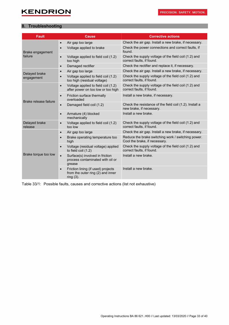
8. Troubleshooting
Fault Cause Corrective actions
Brake engagement failure
• Air gap too large Check the air gap. Install a new brake, if necessary. • Voltage applied to brake Check the power connections and correct faults, if
found. • Voltage applied to field coil (1.2)
too high Check the supply voltage of the field coil (1.2) and correct faults, if found.
• Damaged rectifier Check the rectifier and replace it, if necessary.
Delayed brake engagement
• Air gap too large Check the air gap. Install a new brake, if necessary. • Voltage applied to field coil (1.2)
too high (residual voltage) Check the supply voltage of the field coil (1.2) and correct faults, if found.
Brake release failure
• Voltage applied to field coil (1.2) after power on too low or too high
Check the supply voltage of the field coil (1.2) and correct faults, if found.
• Friction surface thermally overloaded
Install a new brake, if necessary.
• Damaged field coil (1.2) Check the resistance of the field coil (1.2). Install a new brake, if necessary.
• Armature (4) blocked mechanically
Install a new brake.
Delayed brake release
• Voltage applied to field coil (1.2) too low
Check the supply voltage of the field coil (1.2) and correct faults, if found.
Brake torque too low
• Air gap too large Check the air gap. Install a new brake, if necessary. • Brake operating temperature too
high Reduce the brake switching work / switching power. Cool the brake, if necessary.
• Voltage (residual voltage) applied to field coil (1.2)
Check the supply voltage of the field coil (1.2) and correct faults, if found.
• Surface(s) involved in friction process contaminated with oil or grease
Install a new brake.
• Friction lining (if used) projects from the outer ring (2) and inner ring (3).
Install a new brake.
Table 33/1: Possible faults, causes and corrective actions (list not exhaustive)

Operating Instructions BA 86 621..H00 // Last updated: 13/03/2020 // Page 34 of 40
9. Tools and measuring instruments for installation, maintenance and troubleshooting Special tools and measuring instruments are required for installation (Section 4), maintenance (Section 5.1) and troubleshooting (Section 8, list of potential faults not exhaustive). The individual tools and instruments and their applications are described in Table 34/1.
Tools, measuring instruments Description Application
Calibrated torque wrench and Allen key for mounting screws (10 & 15) and set screws (8)
Precise torque-controlled tightening and loosening of the mounting screws (10) of all brake versions and of the mounting screws (15) of brake versions with armature type 200 (see Section 4). Precise torque-controlled tightening and loosening of the set screws (8).
Allen key for mounting screws (10 & 15) and set screws (8)
Tightening and loosening of the mounting screws (10) of all brake versions and of the mounting screws (15) of brake versions with armature type 200 (see Section 4). Tightening and loosening of the set screws (8).
Feeler gauges Checking and measuring the air gap ‘s’ of the mounted brake (see Section 5.1).
Multimeter (voltage, current, resistance) Measuring the supply voltage and ohmic resistance of the field coil (1.2) (see Section 8).
Table 34/1: Tools and measuring instruments for installation, maintenance and troubleshooting IMPORTANT
Tests, service and maintenance operations to be performed on the brake must be carried out by the machine manufacturer’s (motor manufacturer’s) qualified service personnel. The specific maintenance instructions provided by the machine manufacturer (e.g. motor manufacturer) must take account of the requirements specified in Section 5.1 (Maintenance) of these operating instructions.

Operating Instructions BA 86 621..H00 // Last updated: 13/03/2020 // Page 35 of 40
10. Definitions (based on: DIN VDE 0580:2011-11, not exhaustive) Switching torque M1 torque acting on the shaft during brake or clutch slip
Rated torque M2 switching torque specified by the manufacturer to identify the brake. The rated torque M2 is the mean value of at least 3 measurements of the maximum switching torque M1 after completion of the transient response.
Transmissible torque M4 highest torque that can be applied to the engaged brake or clutch without causing the brake/clutch to slip
Residual torque M5 torque transmitted by the released brake or clutch
Load torque M6 torque acting on the drive of the engaged brake or clutch; determined by the power requirement of the driven machine at a given speed
Switching work W heat generated by friction inside the brake or clutch as a result of the switching operation
Maximum switching work Wmax maximum switching work to which the brake or clutch may be exposed
Switching power P switching work converted into heat per unit of time
Maximum switching power Pmax maximum permissible switching work converted into heat per unit of time
Coil ON time t5 time between power on and power off
Coil OFF time t6 time between power off and power on
Total cycle time t7 coil ON time plus coil OFF time
Duty cycle percentage relationship of coil ON time to total cycle time
Switching operation one complete switching on and off operation
Switching frequency Z number of regular switching operations per hour
Response delay during coupling t11 time between power off (releasing systems) or power on (engaging systems) and beginning of torque increase
Rise time t12 time it takes to reach 90% of the M2 rated torque from the beginning of the torque increase
Coupling time t1 response delay t11 plus rise time t12
Response delay during disconnection t21 time between power on (releasing systems) or power off (engaging systems) and beginning of torque decrease
Fall time t22 time it takes for the torque from the beginning of the torque decrease to fall to 10% of the M2 rated torque
Disconnection time t2 response delay t21 plus fall time t22
Slip time t3 time from the beginning of the torque increase up to the end of the braking process (brakes) or until the synchronisation torque M3 has been reached (clutches)
Making time t4 response delay t11 plus slip time t3 (braking or acceleration time)
Operating condition at operating temperature condition at which the steady-state temperature is reached. The operating temperature corresponds to the overtemperature according to DIN VDE 0580 plus the ambient temperature. Unless otherwise specified, the ambient temperature is 35°C.
Overtemperature ∆ϑ31 difference between the temperature of the electromagnetic device or a part thereof and the ambient temperature
Limit temperatures of coil insulating materials in accordance with DIN VDE 0580. The individual insulating materials are classified by insulation classes to DIN IEC 60085.
Rated voltage UN supply voltage specified by the manufacturer for voltage coils to identify the device or component

Operating Instructions BA 86 621..H00 // Last updated: 13/03/2020 // Page 36 of 40
Rated current IB amperage determined by the manufacturer for the specified operating conditions. Unless otherwise specified, the rated current refers to the rated voltage, 20°C winding temperature and to the rated frequency for a given operating mode of voltage windings.
Rated power PN power value to identify the device or component
Rated power at 20°C winding temperature PB determined from the rated current of voltage-controlled devices and components and the R20 resistance at 20°C winding temperature
Other definitions (not included in DIN VDE 0580) applicable to permanent-magnet single-face brakes: Air gap s air gap of released permanent-magnet single-face brake
Rated air gap sN air gap of released permanent-magnet single-face brake when the brake is new
Max. air gap smax maximum air gap at which the brake (just about) still closes at a permanent magnet temperature of 20°C

Operating Instructions BA 86 621..H00 // Last updated: 13/03/2020 // Page 37 of 40
11. Technical specifications Product built and tested to DIN VDE 0580 Brake size 04 06 07 09 11 14 16 Transmissible torque M4 [Nm] 2.2 3.2 11 22 40 80 120
Rated torque M2 [Nm] 2) 2.2 3.2 11 22 40 80 120
Max. speed nmax [rpm] 12000 10000 10000 10000 10000 8000 8000
Max. switching power Pmax [kJ/h] 4 7 8 11 17 29 31
Max. switching work Wmax (Z=1) [kJ] 0.2 0.35 0.4 0.55 0.85 1.45 1.55
Rated power PN [W] 8 12 16 18 24 35 37
Coupling time t1 [ms] 14 19 20 25 25 53 80
Disconnection time t2 [ms] 28 29 29 50 73 97 150
Moment of inertia J [kgcm2] – armature (with flange hub) 0.12 0.38 1.06 3.6 9.5 31.8 57.5
Weight (without flange hub) m [kg] 0.19 0.3 0.6 1.1 1.4 4.1 6
Rated air gap sN +0.1 [mm] 0.2 0.2 0.3 0.3 0.3 0.3 0.3
Max. air gap smax [mm] 0.4 0.5 0.55 0.7 0.8 0.8 0.8
Duty cycle [%] 100
Standard rated voltage [VDC] 24, 205
Insulation class F
Pollution degree 2
Protection rating IP00
Brake type holding brake with emergency stop option or dynamic brake 3)
Table 37/1: Technical specifications Rated operating conditions
Rated voltage tolerance ±10%
Frequency range ±1% of rated frequency
Ambient temperature ϑ13 [°C] -5 to +120
Relative humidity 30% to 80% within ambient temperature range
Other climatic environmental conditions 3Z2 and 3Z4 to EN 60721-3-3
Mechanical environmental conditions 3M8 to EN 60721-3-3
Biological environmental conditions 3B1 to EN 60721-3-3
Mechanically active substances 3S2 to EN 60721-3-3
Chemically active substances 3C1 to EN 60721-3-3
Installation height up to 2000 m a.m.s.l.
Table 37/2: Rated operating conditions for permanent-magnet single-face brake 2) Only with dynamic brakes. 3) Brakes with friction lining.

Operating Instructions BA 86 621..H00 // Last updated: 13/03/2020 // Page 38 of 40
Brake size 04 06 07 09 11 14 16 Switching operations (emergency stops) Z [h-1] 2 4 2 4 2 4 2 4 2 4 2 4 2 4
Maximum switching work Wmax [J] 200 195 350 345 400 395 550 540 850 840 1450 1440 1550 1540
Table 37/1: Maximum switching work Wmax as a function of the number of switching operations (emergency stops) per hour Z (values based on n=3000 rpm)
Brake size 04 06 07 09 11 14 16
Speed n [rpm] 300 250 200 100 100 100 100
Coil ON time t5 [s] 0.3 0.2 0.1 0.15 0.23 0.4 0.4
Coil OFF time t6 [s] 0.3 0.2 0.1 0.15 0.25 0.4 0.45
Break-in period ttotal [min] approx. 5 approx. 5 approx. 2 approx. 3 approx. 4 approx. 4 approx. 5
Table 38/2: Break-in process parameters for the permanent-magnet single-face brake after installation and during brake service life
Explanations on the technical specifications: Wmax (maximum switching work) is the switching work that must not be exceeded during braking operations at maximum speeds of 3000 rpm. Braking operations at speeds greater than 3000 rpm substantially reduce the maximum permissible switching work per switching operation. Such operation must be agreed with the manufacturer. The maximum switching power Pmax is the switching work W that can be converted by the brake per hour. The maximum number of switching operations (emergency stops) Z per hour and the resulting maximum permissible switching work Wmax are specified in Table 37/1. When the brake is used for other applications (e.g. as dynamic brake) the values given in Fig. 37/1 apply. The Pmax and Wmax values are approximate values. They apply to mounted brakes without additional cooling and to emergency stops. The specified times apply to the following conditions: DC side brake switching, operating temperature, rated voltage, and rated air gap. All values are mean values that are subject to variation. In case of AC side brake switching, the coupling time t1 is substantially longer. The specified transmissible torques M4 characterise the torque level of the brakes. Depending on the application the brake is used for, the switching torque M1 and the effective transmissible torque M4 may differ from the specified M4 values. The switching torque M1 depends on the speed (rpm). If the friction surfaces are contaminated with oil, grease or dirt, the transmissible torque M4 and the switching torque M1 may drop. The technical specifications apply after the break-in process has been completed with the specified break-in parameters (see Table 38/2).
10
100
1000
10000
1 10 100 1000 10000h-1
J
Wmax.
Gr. 16Gr. 14Gr. 11Gr. 09Gr. 07Gr. 06Gr. 04
Z
Fig. 38/1: Max. switching work Wmax per switching operation as a function of the number of switching operations per hour Z (values based on n=3000 rpm; applicable to dynamic brakes)
Size 16 Size 14 Size 11 Size 09 Size 07 Size 06 Size 04

Operating Instructions BA 86 621..H00 // Last updated: 13/03/2020 // Page 39 of 40
The rated operating conditions specified in Table 37/2 and the technical specifications in Table 37/1 must be strictly observed during operation of the permanent-magnet single-face brakes. The instructions provided in the PM Line catalogue for brake types 86 621..H00 and in the Technical Customer Information TKU 86 611..H00 must be followed. Specifications subject to change without notice! 12. Product number / type number / version number The product number to be quoted in purchase orders and required to identify the brake version consists of the type number followed by the 4-digit version number. Individual brake types may be available in different versions. So the version number identifies the relevant brake model. Example: Type number: 86 62104H00 Version number: 0001 Product number: 86 62104H00-0001 13. Specialist repair shops Kendrion (Villingen) GmbH Wilhelm-Binder-Str. 4-6 78048 Villingen-Schwenningen Tel: +49 (0)7721 877-1417 Germany 14. Revision history
Date of issue Changes
28/02/2014
Added Declaration of Conformity with RoHS Directive 2011/65/EU and Low Voltage Directive 2006/95/EC Updated rating plate Changed company name
31/03/2016
Low Voltage Directive 2006/95/EC replaced by 2014/35/EU Updated rating plate Added note and warning in Section 8.2.4 Added ambient temperature specification and changed specification of maximum air gap smax for brake size 07 from 0.65 mm to 0.55 mm (Section 10) New layout (design) of operating instructions
13/03/2020 Complete revision of operating instructions Revision of safety information New layout (design) of operating instructions

Operating Instructions 76 43119H03
Operating Instructions BA 86 621..H00 // Last updated: 13/03/2020 // Page 1 of 40