Embed Size (px)
Citation preview
124
Proceedings of Fifth International Conference on Enhanced, Compact and Ultra-Compact Heat Exchangers: Science, Engineering and Technology, Eds. R.K. Shah, M. Ishizuka, T.M. Rudy, and V.V. Wadekar, Engineering Conferences International, Hoboken, NJ, USA, September 2005.
CHE2005 – 17
Optimal Shape Design of Counter-Flow Primary Surface Recuperators
Kenichi MORIMOTO, Yuji SUZUKI and Nobuhide KASAGI
Department of Mechanical Engineering, The University of Tokyo, Hongo, Bunkyo-ku, Tokyo 113-8656, JAPAN.
E-mail: [email protected]
ABSTRACT A series of numerical simulation of the flow and heat transfer in modeled counter-flow heat exchangers with oblique wavy walls is made for optimal shape design of recuperators. The effects of oblique angles and amplitudes of the wavy walls are systematically evaluated, and the heat transfer and pressure loss characteristics are investigated. The flow field is drastically modified due to the counter-rotating streamwise vortices induced by the wavy walls. With the oblique angle of 50-60 degree, significant heat transfer enhancement is achieved at the cost of relatively-small pressure loss, and the j/f factor becomes significantly larger than that of straight square duct or conventional compact recuperators. When thermal coupling of hot and cold fluid passages is considered, the heat transfer is found to be strongly dependent on the arrangement of counter-flow passages. It is found that the j/f factor is increased with the Reynolds number in the range of the present study. Optimal shape design method with adjoint variables of the velocity and thermal fields is also employed in pursuit of maximizing the j/f factor. INTRODUCTION Small-scale distributed energy systems with micro gas turbines have been paid growing attention because of their high efficiency and low environmental impact. Recently, Uechi et al. (2004) showed that one of the most important technical issues for the system efficiency is to enhance the effectiveness of recuperator. Up to now, a number of compact heat exchanger designs have been proposed with various types of heat transfer enhancement technologies (e.g., Kays and London, 1984). Among them, primary surface recuperators have been considered to meet the requirements for low cost and high effectiveness, and employed in recuperated turbine systems (McDonald, 2000). In heat-exchanger passages with modified heat transfer surfaces, considerable heat transfer augmentation is attainable. However, the optimal shape of
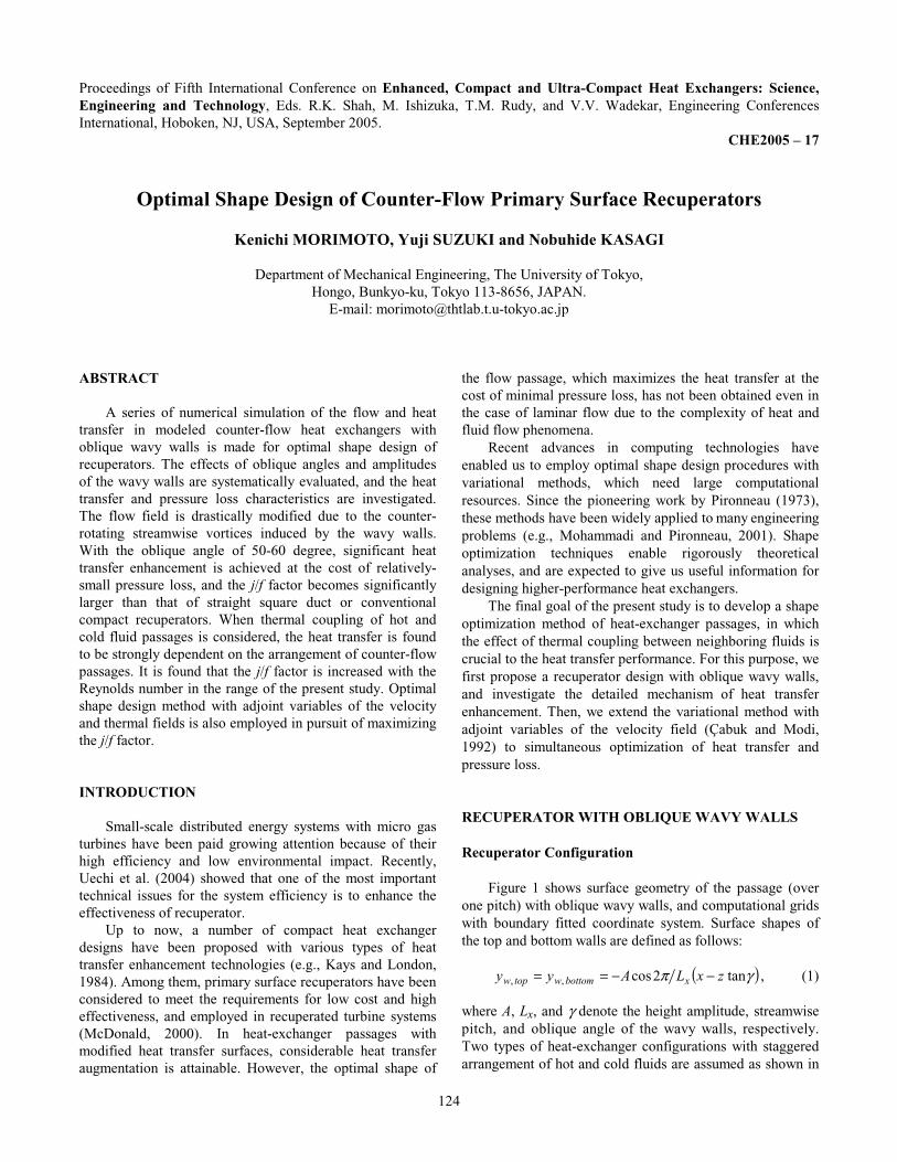
the flow passage, which maximizes the heat transfer at the cost of minimal pressure loss, has not been obtained even in the case of laminar flow due to the complexity of heat and fluid flow phenomena. Recent advances in computing technologies have enabled us to employ optimal shape design procedures with variational methods, which need large computational resources. Since the pioneering work by Pironneau (1973), these methods have been widely applied to many engineering problems (e.g., Mohammadi and Pironneau, 2001). Shape optimization techniques enable rigorously theoretical analyses, and are expected to give us useful information for designing higher-performance heat exchangers. The final goal of the present study is to develop a shape optimization method of heat-exchanger passages, in which the effect of thermal coupling between neighboring fluids is crucial to the heat transfer performance. For this purpose, we first propose a recuperator design with oblique wavy walls, and investigate the detailed mechanism of heat transfer enhancement. Then, we extend the variational method with adjoint variables of the velocity field (Çabuk and Modi, 1992) to simultaneous optimization of heat transfer and pressure loss. RECUPERATOR WITH OBLIQUE WAVY WALLS Recuperator Configuration Figure 1 shows surface geometry of the passage (over one pitch) with oblique wavy walls, and computational grids with boundary fitted coordinate system. Surface shapes of the top and bottom walls are defined as follows: ( )γπ tan2cos , , zx −−== xbottomwtopw LAyy , (1) where A, Lx, and γ denote the height amplitude, streamwise pitch, and oblique angle of the wavy walls, respectively. Two types of heat-exchanger configurations with staggered arrangement of hot and cold fluids are assumed as shown in
125
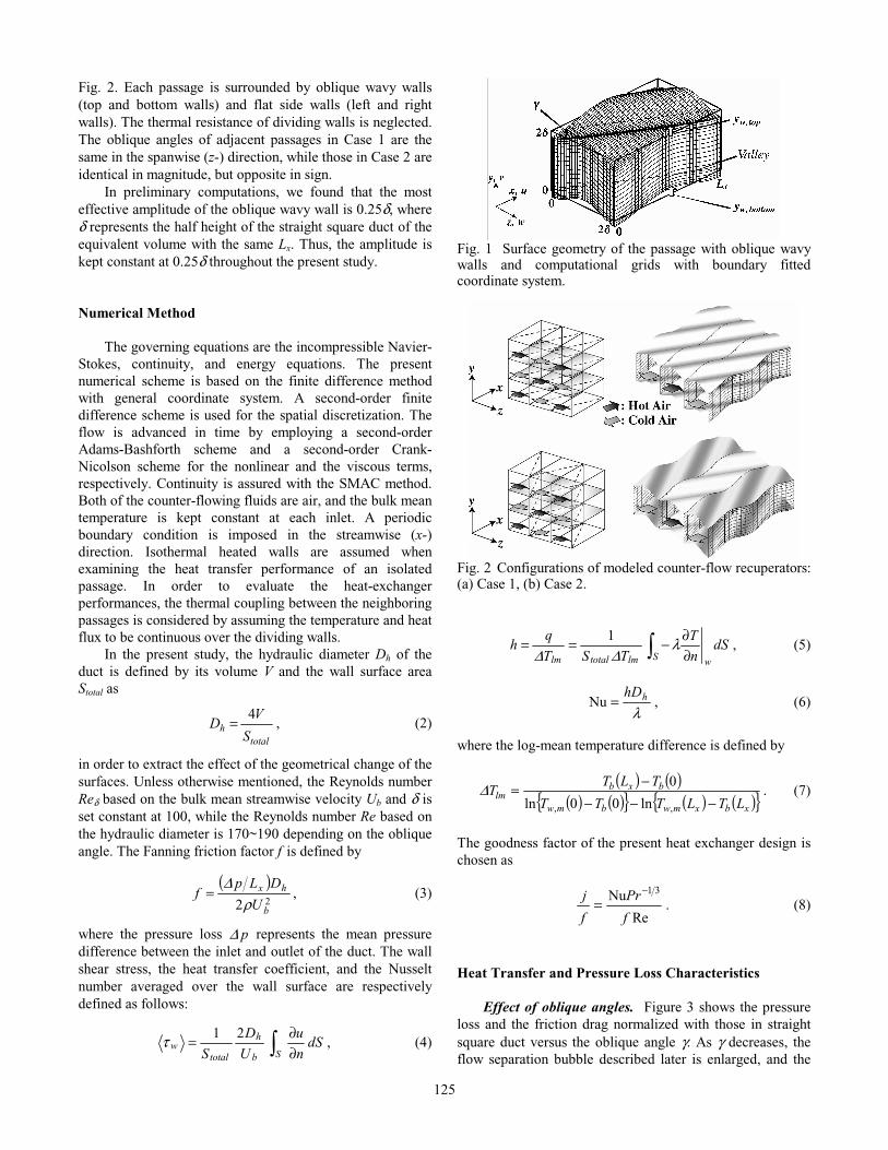
Fig. 2. Each passage is surrounded by oblique wavy walls (top and bottom walls) and flat side walls (left and right walls). The thermal resistance of dividing walls is neglected. The oblique angles of adjacent passages in Case 1 are the same in the spanwise (z-) direction, while those in Case 2 are identical in magnitude, but opposite in sign. In preliminary computations, we found that the most effective amplitude of the oblique wavy wall is 0.25δ, where δ represents the half height of the straight square duct of the equivalent volume with the same Lx. Thus, the amplitude is kept constant at 0.25δ throughout the present study. Numerical Method The governing equations are the incompressible Navier-Stokes, continuity, and energy equations. The present numerical scheme is based on the finite difference method with general coordinate system. A second-order finite difference scheme is used for the spatial discretization. The flow is advanced in time by employing a second-order Adams-Bashforth scheme and a second-order Crank-Nicolson scheme for the nonlinear and the viscous terms, respectively. Continuity is assured with the SMAC method. Both of the counter-flowing fluids are air, and the bulk mean temperature is kept constant at each inlet. A periodic boundary condition is imposed in the streamwise (x-) direction. Isothermal heated walls are assumed when examining the heat transfer performance of an isolated passage. In order to evaluate the heat-exchanger performances, the thermal coupling between the neighboring passages is considered by assuming the temperature and heat flux to be continuous over the dividing walls. In the present study, the hydraulic diameter Dh of the duct is defined by its volume V and the wall surface area Stotal as
total
hS
VD
4= , (2)
in order to extract the effect of the geometrical change of the surfaces. Unless otherwise mentioned, the Reynolds number Reδ based on the bulk mean streamwise velocity Ub and δ is set constant at 100, while the Reynolds number Re based on the hydraulic diameter is 170~190 depending on the oblique angle. The Fanning friction factor f is defined by
( )
22
b
hx
U
DLpf
ρ∆
= , (3)
where the pressure loss p ∆ represents the mean pressure difference between the inlet and outlet of the duct. The wall shear stress, the heat transfer coefficient, and the Nusselt number averaged over the wall surface are respectively defined as follows:
∫ ∂∂=
Sb
h
totalw dS
n
u
U
D
S
21τ , (4)
Fig. 1 Surface geometry of the passage with oblique wavy walls and computational grids with boundary fitted coordinate system.
Fig. 2 Configurations of modeled counter-flow recuperators: (a) Case 1, (b) Case 2.
∫ ∂∂−==
S wlmtotallmdS
n
T
TST
qh
1 λ∆∆
, (5)
λ
hhD=Nu , (6)
where the log-mean temperature difference is defined by
( ) ( )
( ) ( ) ( ) ( ) xbxmwbmw
bxblm
LTLTTT
TLTT
−−−−=
,, ln00ln
0∆ . (7)
The goodness factor of the present heat exchanger design is chosen as
Re
Nu 31
f
Pr
f
j −= . (8)
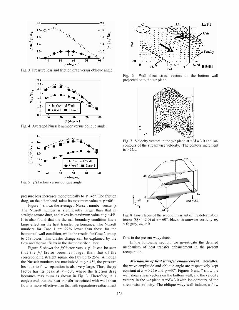
Heat Transfer and Pressure Loss Characteristics Effect of oblique angles. Figure 3 shows the pressure loss and the friction drag normalized with those in straight square duct versus the oblique angle γ. As γ decreases, the flow separation bubble described later is enlarged, and the
126
Fig. 3 Pressure loss and friction drag versus oblique angle.
Fig. 4 Averaged Nusselt number versus oblique angle.
Fig. 5 j / f factors versus oblique angle. pressure loss increases monotonically to γ ~ 45º. The friction drag, on the other hand, takes its maximum value at γ ~ 60º. Figure 4 shows the averaged Nusselt number versus γ. The Nusselt number is significantly larger than that in straight square duct, and takes its maximum value at γ ~ 45º. It is also found that the thermal boundary condition has a large effect on the heat transfer performance. The Nusselt numbers for Case 1 are 22% lower than those for the isothermal wall condition, while the results for Case 2 are up to 5% lower. This drastic change can be explained by the flow and thermal fields in the duct described later. Figure 5 shows the j/f factor versus γ. It can be seen that the j/f factor becomes larger than that of the corresponding straight square duct by up to 25%. Although the Nusselt numbers are maximized at γ ~ 45º, the pressure loss due to flow separation is also very large. Thus, the j/f factor has its peak at γ ~ 60º, where the friction drag becomes maximum as shown in Fig. 3. Therefore, it is conjectured that the heat transfer associated with wall shear flow is more effective than that with separation-reattachment
Fig. 6 Wall shear stress vectors on the bottom wall projected onto the x-z plane.
Fig. 7 Velocity vectors in the y-z plane at x /δ = 3.0 and iso-contours of the streamwise velocity. The contour increment is 0.2Ub.
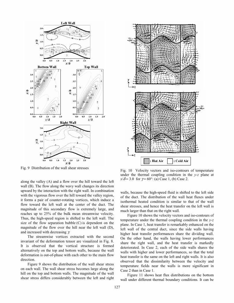
Fig. 8 Isosurfaces of the second invariant of the deformation tensor (Q < −2.0) at γ = 60°: black, streamwise vorticity ω x < 0; gray, ω x > 0. flow in the present wavy ducts. In the following section, we investigate the detailed mechanism of heat transfer enhancement in the present recuperator. Mechanism of heat transfer enhancement. Hereafter, the wave amplitude and oblique angle are respectively kept constant at A = 0.25δ and γ = 60º. Figures 6 and 7 show the wall shear stress vectors on the bottom wall, and the velocity vectors in the y-z plane at x/δ = 3.0 with iso-contours of the streamwise velocity. The oblique wavy wall induces a flow
127
Fig. 9 Distribution of the wall shear stresses along the valley (A) and a flow over the hill toward the left wall (B). The flow along the wavy wall changes its direction upward by the interaction with the right wall. In combination with the vigorous flow over the hill toward the valley region, it forms a pair of counter-rotating vortices, which induce a flow toward the left wall at the center of the duct. The magnitude of this secondary flow is extremely large, and reaches up to 25% of the bulk mean streamwise velocity. Thus, the high-speed region is shifted to the left wall. The size of the flow separation bubble (C) is dependent on the magnitude of the flow over the hill near the left wall (D), and increased with decreasing γ. The streamwise vortices extracted with the second invariant of the deformation tensor are visualized in Fig. 8. It is observed that the vortical structure is formed alternatively on the top and bottom walls, because the wall deformation is out-of-phase with each other to the main flow direction. Figure 9 shows the distribution of the wall shear stress on each wall. The wall shear stress becomes large along the hill on the top and bottom walls. The magnitude of the wall shear stress differs considerably between the left and right
Fig. 10 Velocity vectors and iso-contours of temperature under the thermal coupling condition in the y-z plane at x/δ = 3.0 for γ = 60°: (a) Case 1, (b) Case 2. walls, because the high-speed fluid is shifted to the left side of the duct. The distribution of the wall heat fluxes under isothermal heated condition is similar to that of the wall shear stresses, and hence the heat transfer on the left wall is much larger than that on the right wall. Figure 10 shows the velocity vectors and iso-contours of temperature under the thermal coupling condition in the y-z plane. In Case 1, heat transfer is remarkably enhanced on the left wall of the central duct, since the side walls having higher heat transfer performances share the dividing wall. On the other hand, the walls having lower performances share the right wall, and the heat transfer is markedly deteriorated. In Case 2, each of the side walls shares the walls with higher and lower performances, so that the total heat transfer is the same on the left and right walls. It is also observed that the dissimilarity between the velocity and temperature fields near the walls is more significant in Case 2 than in Case 1. Figure 11 shows heat flux distributions on the bottom wall under different thermal boundary conditions. It can be
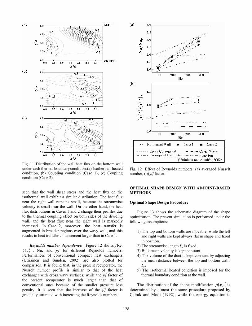
128
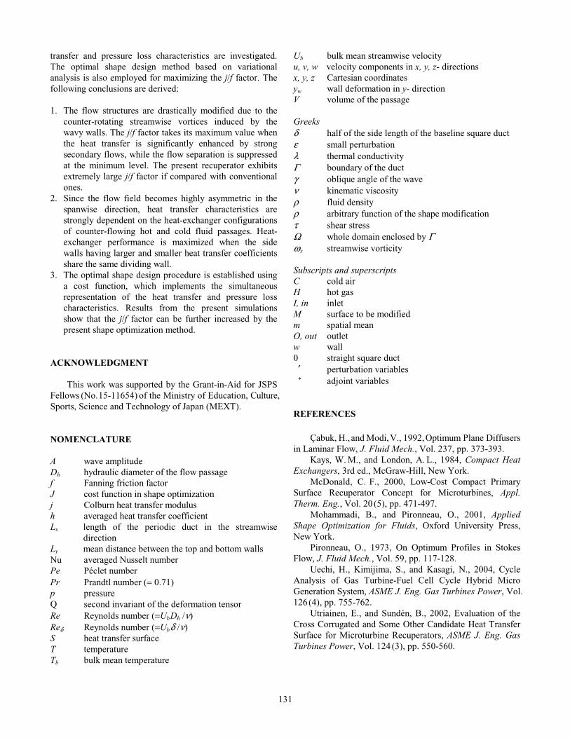
Fig. 11 Distribution of the wall heat flux on the bottom wall under each thermal boundary condition: (a) Isothermal heated condition, (b) Coupling condition (Case 1), (c) Coupling condition (Case 2). seen that the wall shear stress and the heat flux on the isothermal wall exhibit a similar distribution. The heat flux near the right wall remains small, because the streamwise velocity is small near the wall. On the other hand, the heat flux distributions in Cases 1 and 2 change their profiles due to the thermal coupling effect on both sides of the dividing wall, and the heat flux near the right wall is markedly increased. In Case 2, moreover, the heat transfer is augmented in broader regions over the wavy wall, and this results in heat transfer enhancement larger than in Case 1. Reynolds number dependence. Figure 12 shows f Re, τ w , Nu, and j/f for different Reynolds numbers.
Performances of conventional compact heat exchangers (Utriainen and Sundén, 2002) are also plotted for comparison. It is found that, in the present recuperator, the Nusselt number profile is similar to that of the heat exchanger with cross wavy surfaces, while the j/f factor of the present recuperator is much larger than that of conventional ones because of the smaller pressure loss penalty. It is seen that the increase of the j/f factor is gradually saturated with increasing the Reynolds numbers.
Fig. 12 Effect of Reynolds numbers: (a) averaged Nusselt number, (b) j/f factor. OPTIMAL SHAPE DESIGN WITH ADJOINT-BASED METHODS Optimal Shape Design Procedure Figure 13 shows the schematic diagram of the shape optimization. The present simulation is performed under the following assumptions: 1) The top and bottom walls are movable, while the left
and right walls are kept always flat in shape and fixed in position.
2) The streamwise length Lx is fixed. 3) Bulk mean velocity is kept constant. 4) The volume of the duct is kept constant by adjusting
the mean distance between the top and bottom walls Ly.
5) The isothermal heated condition is imposed for the thermal boundary condition at the wall.
The distribution of the shape modification ( )Γρ x is determined by almost the same procedure proposed by Çabuk and Modi (1992), while the energy equation is

129
Fig. 13 Schematic of the shape optimization. additionally incorporated into the optimization procedure for taking into account the heat transfer characteristics. The cost function J to be maximized is defined as follows:
( ) 0
0,
1Qd
n
T
PePpdJ
MOIM ∫∫ ∂
∂+=ΓΓΓ
ΓβΓΓ , (9)
where the first and second terms respectively represent the mean pressure loss between the inlet and outlet boundaries, and heat transfer integrated over the entire walls. Each term is normalized with the absolute quantity in straight square duct. In Eq. (9), β represents the weighting factor of heat transfer to pressure loss, and is set to unity in the present simulation. Hereafter, the following formulations are written in the Cartesian coordinates for simplicity. The Navier-Stokes and energy equations in steady forms are
.in 0
1
,01
,0
,,
,,,,
Ω=−
=−+=
jjjj
jjiijijii
TPe
Tu
uRe
puuu (10)
where the velocity and pressure are nondimensionalized by Ub, δ, and ν, and T corresponds to the temperature difference from the wall temperature Tw. Let ( )Tup i ′′′ , , be respectively the variations of ( )Tup i , , in response to the shape modification of the passage from ΓM to ΓMε as shown in Fig. 13. Then, ( )Tup i ′′′ , , satisfy the following set of perturbed equations:
.in 0
1
,01
,0
,,,
,,,,,
Ω=′−′+′
=′−′+′+′=′
jjjjjj
jjiijijjijii
TPe
TuTu
uRe
puuuuu (11)
Since the velocity and thermal fields respectively satisfy the non-slip and isothermal wall condition on ΓM, the following relations can be derived by using Taylor series expansions:
.on and , Mi
in
TT
n
uu Γρρ
∂∂−=′
∂∂−=′ (12)
Now we introduce the adjoint variables ( )*** , , Tup i , which satisfy the following adjoint equations:
( )
.in 01
,01
,0
*,
*,
*,
*,
*,
*,
*,
*,
Ω=−−
=−+−+=
jjjj
ijjiiijjijii
TPe
Tu
TTuRe
puuuu (13)
Then, by using the divergence theorem, the first variation of the cost function, δ J, can be identified as
∫
∂
∂∂∂−
∂∂
∂∂=
M
dn
T
n
T
Pen
u
n
u
RePJ ii
ΓΓρδ
**
0
111 , (14)
where the following boundary conditions are imposed on the perturbation and adjoint variables:
OIi Tu ΓΓ ,on 0 ,0 =′=′ , (15)
( ) Mi Const.Q
PTu Γβ on ,0
0
0** === . (16)
At the inlet and outlet boundaries, a periodic boundary condition is imposed on the adjoint variables, instead of the inflow and outflow conditions employed in the procedure of Çabuk and Modi (1992). We employ a simple gradient method, and determine
( )Γρ x as
( )n
T
n
T
Pen
u
n
u
Reii
∂∂
∂∂−
∂∂
∂∂
=** 11
Γρ x . (17)
Therefore, δ J is always positive from Eq. (14), which ensures positive changes in J. The optimization procedure is summarized as follows: 1) Set an initial surface geometry. 2) Generate a computational grid. 3) Solve the Navier-Stokes equation for ( )iup , , and
the energy equation for T. 4) Solve the adjoint equations for ( )** , iup and *T . 5) Modify the surface shape by using Eq. (17). 6) Smooth the surface modified in Step 5 to avoid
numerical instability. 7) Iterate steps 2 - 6 until the cost function converges. For the ease of the grid generation, each grid point is assumed movable only in the y-direction, while fixed in the

130
Fig. 14 Shape modification: (a) Movement of the boundary grid points in the y-direction, (b) Relocation of the grid point.
Fig. 15 History of the cost function and j/f factor. x- and z- directions. Boundary grid points on the top and bottom walls are generated in the following ways. As shown in Fig. 14 (a), each grid point kiP , is projected in the y-direction onto the plane QPP kiki 1,,1 +− , where the point Q is calculated from ( )nερ=QP ki, . Next, in Step 6, each grid point is adjusted in the y-direction to avoid sharp irregularity. As shown in Fig. 14 (b), kiP ,
~ obtained in Step 5 is moved to
kiP ,~′ , which is the midpoint of RP ki,
~ , if the corner angle α defined by kikiki PPP ,1,,1
~~~+−∠ or 1,,1,
~~~+−∠ kikiki PPP is smaller than
a prescribed threshold of π32 . Here, the point R is the foot of a perpendicular of kiP ,
~ onto kiki PP ,1,1
~~+− or 1,1,
~~+− kiki PP . This
process is repeated until the minimum angle becomes larger than the threshold value in both x- and z- directions. In this study, ε is set constant such that the magnitude of the wall deformation is kept less than 0.05δ. Results of the Optimization The initial recuperator shape is chosen as the passage with oblique wavy walls presented in the previous sections (A = 0.25δ, γ = 60º in Eq. (1)). The Reynolds number defined by Ub and δ is kept constant at 100 during the optimization. Figure 15 shows the history of the cost function J and the corresponding change of the j/f factor. The cost function is increased monotonically with successive iterations and reaches its maximum at the 5th iteration. The j/f factor takes its maximum value at the 5th iteration as well, and about 3% improvement is achieved. Whereas the pressure loss f Re is almost the same as the initial case, the contribution of the
Fig. 16 Modified structure at the 5th iteration: (a) Cumulative surface modification from the initial shape to the 5th step on the bottom wall, (b) Wall shear stress vectors on the bottom wall. skin friction is increased. Therefore, it is conjectured that the increase in the averaged Nusselt number is due to the reduction of the separation bubble and thus the enhancement of heat transfer associated with the wall shear flow. It is noted that, after the 7th iteration, computation diverges due to the appearance of locally-steep surfaces unresolvable with the present grid system. Figure 16 shows cumulative surface modification from the initial state to the 5th step, and the wall shear stress vectors on the bottom wall at the 5th iteration. It can be seen that there is large negative deformation on both sides of the hill region. Thus, the shape of the hill becomes steeper than the initial shape, and the valley region becomes leveled. With this modification, the flow over the hill near the left wall (D) is kept attached to the wall and the flow separation region of the valley (C) in the initial case is diminished. Therefore, it is anticipated that, in the neighborhood of the present initial shape with oblique wavy walls, the maximum j/f factor would be achieved by enhancing the wall shear flow and suppressing the flow separation simultaneously. CONCLUSIONS A series of numerical simulation of the flow and heat transfer in modeled counter-flow heat exchangers with oblique wavy walls is made for optimal shape design of recuperators. The effects of oblique angles and amplitudes of the wavy walls are systematically evaluated, and the heat
131
transfer and pressure loss characteristics are investigated. The optimal shape design method based on variational analysis is also employed for maximizing the j/f factor. The following conclusions are derived: 1. The flow structures are drastically modified due to the
counter-rotating streamwise vortices induced by the wavy walls. The j/f factor takes its maximum value when the heat transfer is significantly enhanced by strong secondary flows, while the flow separation is suppressed at the minimum level. The present recuperator exhibits extremely large j/f factor if compared with conventional ones.
2. Since the flow field becomes highly asymmetric in the spanwise direction, heat transfer characteristics are strongly dependent on the heat-exchanger configurations of counter-flowing hot and cold fluid passages. Heat-exchanger performance is maximized when the side walls having larger and smaller heat transfer coefficients share the same dividing wall.
3. The optimal shape design procedure is established using a cost function, which implements the simultaneous representation of the heat transfer and pressure loss characteristics. Results from the present simulations show that the j/f factor can be further increased by the present shape optimization method.
ACKNOWLEDGMENT This work was supported by the Grant-in-Aid for JSPS Fellows (No. 15-11654) of the Ministry of Education, Culture, Sports, Science and Technology of Japan (MEXT). NOMENCLATURE A wave amplitude Dh hydraulic diameter of the flow passage f Fanning friction factor J cost function in shape optimization j Colburn heat transfer modulus h averaged heat transfer coefficient Lx length of the periodic duct in the streamwise
direction Ly mean distance between the top and bottom walls Nu averaged Nusselt number Pe Péclet number Pr Prandtl number (= 0.71) p pressure Q second invariant of the deformation tensor Re Reynolds number (=Ub Dh /ν) Reδ Reynolds number (=Ub δ /ν) S heat transfer surface T temperature Tb bulk mean temperature
Ub bulk mean streamwise velocity u, v, w velocity components in x, y, z- directions x, y, z Cartesian coordinates yw wall deformation in y- direction V volume of the passage Greeks δ half of the side length of the baseline square duct ε small perturbation λ thermal conductivity Γ boundary of the duct γ oblique angle of the wave ν kinematic viscosity ρ fluid density ρ arbitrary function of the shape modification τ shear stress Ω whole domain enclosed by Γ ω x streamwise vorticity Subscripts and superscripts C cold air H hot gas I, in inlet M surface to be modified m spatial mean O, out outlet w wall 0 straight square duct
′ perturbation variables * adjoint variables
REFERENCES Çabuk, H., and Modi, V., 1992, Optimum Plane Diffusers in Laminar Flow, J. Fluid Mech., Vol. 237, pp. 373-393. Kays, W. M., and London, A. L., 1984, Compact Heat Exchangers, 3rd ed., McGraw-Hill, New York. McDonald, C. F., 2000, Low-Cost Compact Primary Surface Recuperator Concept for Microturbines, Appl. Therm. Eng., Vol. 20 (5), pp. 471-497. Mohammadi, B., and Pironneau, O., 2001, Applied Shape Optimization for Fluids, Oxford University Press, New York. Pironneau, O., 1973, On Optimum Profiles in Stokes Flow, J. Fluid Mech., Vol. 59, pp. 117-128. Uechi, H., Kimijima, S., and Kasagi, N., 2004, Cycle Analysis of Gas Turbine-Fuel Cell Cycle Hybrid Micro Generation System, ASME J. Eng. Gas Turbines Power, Vol. 126 (4), pp. 755-762. Utriainen, E., and Sundén, B., 2002, Evaluation of the Cross Corrugated and Some Other Candidate Heat Transfer Surface for Microturbine Recuperators, ASME J. Eng. Gas Turbines Power, Vol. 124 (3), pp. 550-560.