Embed Size (px)
Citation preview

1
Wei Kan Wang, Schlumberger
KEY TECHNICAL CONSIDERATIONS FOR SUCCESSFUL HYDRAULIC FRACTURING OF
HPHT WELLS
Visegrád, 21 November 2013
2
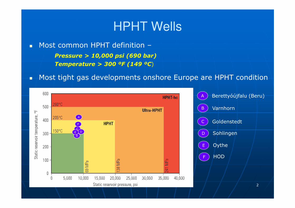
HPHT Wells
� Most common HPHT definition –
Pressure > 10,000 psi (690 bar)
Temperature > 300 ºF (149 ºC)
� Most tight gas developments onshore Europe are HPHT condition
A
A Berettyóújfalu (Beru)
B Varnhorn
B
C
GoldenstedtC
SohlingenDD
OytheE
E
HODF
F

3
Setting the Scene
� Reservoir • Depth – ~ 3700 - 4200 m TVD
• Lithology – Tight Sandstone
• Temperature – ~ 150 – 210 ºC
• Reservoir Pressure – ~ 600 – 700 bar
• Permeability –
• Porosity –
• Reservoir Fluids – Gas, sometimes with condensate
• Contaminants – may contain CO2, H2S
� Production• Pre- Fracturing –
• Post- Fracturing –

4
HPHT Tight Gas: Hydraulic Fracturing
Kf: Prop Pack Perm
W: Fracture Width
K: Formation Perm
Xf: Frac Half Length
Long Fracture & small width
Avg. Prop. Conc. = 2 #/sq.ft.Low perm
Effective Wellbore Radius ~ 0.5 Xf (Fcd > 10)
Saih Rawl Database (Oman)
• Fracture Length (Xf) is inversely
proportional to formation perm (k)

5
Challenges of HPHT Well Fracturing
HT
HP
� Materials designed for high/ultra temperature applications:- Fracturing fluids
- Completions, and zonal isolation
- Perf guns, Testing...etc
� Minimize surface treating pressure:- Optimized perforation strategy in high stress zones
- Breakdown / Diagnostic injections
- Fluids initiatives (low friction, high density..etc)
� An integrated workflow based on reservoir characterization:- MEM: predicting the stress
- Fracturing stage placement / zonal coverage (stress profile)
� Materials designed for high pressure / stress applications:
- Proppants
6
Solutions for High Temperature

7
HT Fracturing Fluids Requirement
• Place all proppant without screen-out
• Robust fluid design with location water, chem
• Maximize fracture half length
• Maintain leakoff control
• Delayed viscosity generation
• Maximized Clean-up/Conductivity
• Proppant Suspension @ BH Temperature
• Retained Viscosity at Pressure
• Shear–Rate Regimes
Ease of Design
Fluid Efficiency
Stability
HPHT Reservoirs exacerbate BH challenges in fracturing, require unique, robust technological advances

8
Desired Viscosity Profile
1. Low-intermediate viscosity in tubing
2. Complete crosslinking at high temperature (propagate frac, suspendproppant)
3. Sufficient fluid stability with time at high temperatures
4. Reduced fluid viscosity (break) after proppant is placed
Time
4321
Viscosity
Temperature

9
High / Ultra Temperature Fluids
300°F 325°F 350°F 375°F 400°F 425°F 450°F
149°C 163°C 177°C 191°C 204°C 218°C 232°C
• Borate Crosslinked Fluids
• CMHPG Zirconium Crosslinked Fluids
• Synthetic Guar Fluids
- Requires water introduction for formation cool down- Fluid at tip may not be able to grow in length - Low prop pack conductivity due to high gel loading
- Developed for ultra temperatures: 350 – 450 ºF
- Performance of early version CMHPG fluidusually compromised for:o Shear –sensitivityo Crosslink too early / too late
- Later generation CMHPG fluid:o Overcome shortage of earlier versiono Most commonly applied in onshore
Europe HT wells recent yearso Stretched in ultra temp wells ThermaFRAC* SAPPHIRE XF
TemperatureRatings

10
ThermaFRAC* Fluid (200 - 375 ºF)
Crosslinking too early� High-friction� Shear degradation� Screenout
Crosslinking too late� Low viscosity� Small fracture width� Screenout
What is the temperature at the perforations?
Shear Tolerance Controllable Viscosity Retained Perm
Viscosity Development
ThermaFRAC*
Earlier CMHPG

11
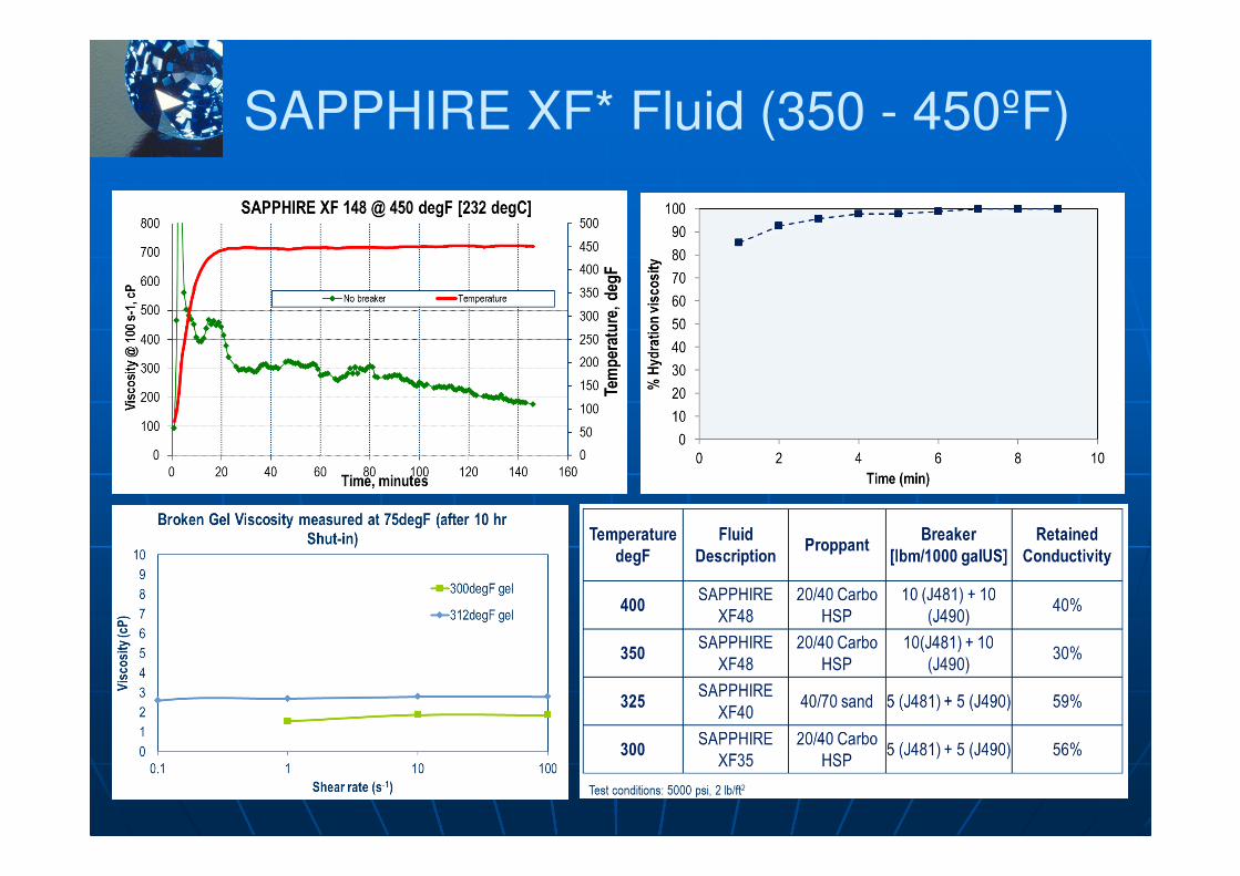
SAPPHIRE XF* Fluid (350 - 450ºF)
Polymer • Synthetic polymer for HT applications
Crosslinker & Delay• HT crosslinker component
• Combined approach of chemical & temperature delay
Surfactants
• Surfactants acting as flow back aids to minimize risk of water block
pH Buffer• Ensuring fast polymer hydration for high pump rate
Temperature stabilizer• Chemical stabilization of polymer for high temperature application
Breaker• Active breaker & encapsulated breaker forcontrolled viscosity reduction
12
SAPPHIRE XF* Fluid (350 - 450ºF)

13
SAPPHIRE XF* Fluid (350 - 450ºF)
� 2 jobs in India
� 20 BPM upto 8 PPA @ 357ºF & 395ºF
� Per stage ~ 2000 bbl fluid
� Per stage ~ 170,000 lb Proppant
� 3 jobs in USA
� 60 BPM upto 5 PPA @ 300ºF
� Per job ~ 4000 bbl fluid
� Per job ~ 192,000 lb Proppant
� Planning for BP in Jordan

14
Solutions for High Pressure

15
Reservoir-Centric Integrated Workflow
StructureLithology
DFN
GeomechanicalModel
Staging & Perforating
Complex Hydraulic Fracture Models
MicroseismicMapping
Automated Gridding
Reservoir Simulation
� Integrated workflow supports seismic-to-simulation modeling
� Hydraulic Fracturing permanentlyalters the reservoir

16
Tight Gas Sand Fracturing Design
� Where to initiate frac ?
� Staging/zonal coverage ?
1. Data Integration / Zoning
2. Identify Pay Zone
3. Identify Frac Units
4. Staging & Perforations

17
Treating Pressure
� Breakdown Gradient = 1.2 psi/ft (0.27 bar/m)
� NWB Friction = 1000 psi (69 bar)
� Fluid Friction = 340 psi (23 bar) @ 8 BPM
Psuf = PBD – Phyd + Pfric + Pnwb
Psuf = 1080 bar – 396 bar + 23 bar + 69 bar
PPPPsufsufsufsuf = = = = 776 bar776 bar776 bar776 bar
PPPPsufsufsufsuf = = = = (P(P(P(PBDBDBDBD) + ) + ) + ) + PPPPfracfracfracfrac –––– PPPPhydhydhydhyd ++++PPPPnetnetnetnet + + + + PPPPfricfricfricfric+ + + + PPPPnwbnwbnwbnwb
Psuf
Pfriction
Pfrac
Phyd
Pnet
Pnwb
Pbreakdown
Predict High Density (?)
Predict Fluid Property
Minimize
� Frac Gradient = 1.0 psi/ft (0.23 bar/m)
� NWB Friction = 1500 psi (103 bar)
� Net Pressure = 1000 psi (69 bar)
� Fluid Friction = 1700 psi (117 bar) @ 30BPM
4000 m TVD
Psuf = PFRAC – Phyd + Pfric + Pnwb + Pnet
Psuf = 920 bar – 396 bar + 117 bar + 103 bar + 69 bar
PPPPsufsufsufsuf = = = = 813 bar813 bar813 bar813 bar

18
Achieving a Better NWB Connection
� Connection between wellbore and hydraulic fracturing (throughperforations) are extremely important for:
• Formation Breakdown
• NWB friction –perforations / tortuosity
stress concentration
proppant admittance
� Basic perforation requirements:
• Penetration: 4~6 in (~12 cm) into formation
• Perf hole size: 9 x Dpr_ave
• 2 shots / BPM
• 60 º phasing
� Abrasive jetting has been applied in several HTHP wells onshoreEurope to lower down breakdown pressure, perforation friction

19
Additional Technology

20
Ultra High Strength Proppant Technology
CARBO KRYPTO SPHERE SAINT GOBAIN TITAN 3050
� Retains integrity at 20,000 psi closure
� Single mesh size product (any size)
� Twice baseline conductivity at 20,000 psi compared to typical HSP
� Spherical shape and smooth surface to
significantly reduce erosion
� Industry’s first beyond conventional
� Rated 20000, 25000, 30000 psi
� Available in 30/50 meshh

21
HiWay* Flow Channel Frac Technology
Reliable service, proven solution
� > 13,800 treatments (> 1,200 wells) in 16 countries
� Variety of formations (carbonate, sandstone, shale)
� Unprecedented proppant placement rate (99.9%)
� ~ 700 screen-outs prevented to date
More Value with Less Resources Demanding
Significant impact on production
� >20% increase in tight formations
Significant reduction in logistics, safety risks and
environmental footprint. Reductions in:
� Water and proppant consumption per job of 25% and 42%,
respectively;
� > 540 million gallons of water and > 1.8 billion lbs of
proppant saved so far;
� > 80,000 proppant and water hauling road journeys
� ~ 18 million lbs of CO2 emissions avoided
Paradigm shift in hydraulic fracturing technology
2121

22
Conclusion
� Fracturing fluid technology developments facilitate thechallenges of ultra-high-temperature reservoirs.
� Success of hydraulic fracturing in HTHP wells lies on theapplication of proper workflow, includes multi-disciplinecontributions:
• Materials technology for HTHP application
• Reservoir description and data integration
• Proper staging to achieve optimum zonal coverage
• Proper perf strategy to minimize treating pressure
� Based on well conditions, “out of box” additional technology may be tested to evaluate its applicability onshore Europe.

23
Thank Your&
Discussions


![Technical Considerations [Autosaved].pptx](https://img.pdfslide.net/doc/110x75/563db908550346aa9a996217/technical-considerations-autosavedpptx.jpg)