Embed Size (px)
Citation preview
KINETICS™ Seismic & Wind Design Manual Section D9.0
SECTION D9.0 – TABLE OF CONTENTSPAGE 1 of 1 SECTION – D9.0B
Toll Free (USA Only): 800-959-1229 RELEASED ON: 4/22/2014International: 614-889-0480FAX 614-889-0540World Wide Web: www.kineticsnoise.comE-mail: [email protected]
Dublin, Ohio, USA Cambridge, Ontario, Canada
SECTION D9.0 – TABLE OF CONTENTS
Title SectionRevision Record D9.0A
D9.0 – Electrical Distribution Systems
Title Section
Seismic Forces Acting On Cable Trays & Conduit D9.1
Basic Primer for the restraint of Cable Trays & Conduit D9.2
Pros and Cons of Struts versus Cables D9.3
Layout Requirements for Conduit/Tray Restraint Systems
Requirements for Conduit/Tray Restraints D9.4.1(Definitions and Locating Requirements)
Ceiling Supported Conduit/Tray Restraint Arrangements D9.4.2
Floor Supported Conduit/Tray Restraint Arrangements D9.4.3
Conduit/Tray Restraint System Attachment Details
Transferring Forces D9.5.1
Cable Clamp Details D9.5.2
Conduit/Tray Attachment Details D9.5.3
Structure Attachment Details D9.5.4
Non-Moment Generating Connections D9.5.5
Connection Options for Awkward Situations D9.6
KINETICS™ Seismic & Wind Design Manual Section D9.1
SEISMIC FORCES ACTING ON ELECTRICAL DISTRIBUTION SYSTEMSPAGE 1 of 3 SECTION – D9.1
Toll Free (USA Only): 800-959-1229 RELEASED ON: 4/22/2014International: 614-889-0480FAX 614-889-0540World Wide Web: www.kineticsnoise.comE-mail: [email protected]
Dublin, Ohio, USA Cambridge, Ontario, Canada
SEISMIC FORCES ACTING ON ELECTRICAL DISTRIBUTION SYSTEMS
When subjected to an earthquake, electrical distribution systems must resist lateral and axialbuckling forces, and the restraint components for these systems must resist pullout andlocalized structural failures.
Most electrical distribution systems are suspended from the deck above on fixed hanger rodsystems. They may be supported singly or there may be several pieces of conduit or bussducts attached to a common trapeze. On some occasions the conduit may run vertically ormay be mounted to the floor.
D9.1.1 Suspended Systems
Most codes do not require that electrical distribution supported on non-moment generating(swiveling) hanger rods 12 in or less in length be restrained. The 12 in length was determinedbased on the natural frequency of systems supported on the short hanger rods. In practice, ithas been found that the vibrations generated by earthquakes do not excite these types ofsystems and, although the systems move back and forth somewhat as a result of anearthquake, they do not tend to oscillate severely and tear themselves apart.
There are also exclusions in most codes for small pieces of conduit, no matter what the hangerrod length. Again, the basis for this exclusion is based on the post-earthquake review of manyinstallations. It has been found that smaller conduit runs are light and flexible enough that theycannot generate enough energy to do significant damage to themselves.
For cases where restraints are required, however, the forces involved can be significant. Thisis due to the difference between the spacing of the system supports and their restraints.Supports for these systems are typically sized to carry approximately a 10 ft length of conduitor duct (in the case of trapezes, multiple pieces of conduit each approx 10 ft long). Seismicrestraints, on the other hand, are normally spaced considerably further apart with the spacingvarying by restraint type, restraint capacity, conduit size, and the seismic design load. It isvery important to be aware of the impact of the difference in spacing as the wider this spacing,the larger the seismic load when compared to the support load. Guidance in determiningrestraint spacing requirements is available in Chapter D4 of this manual. (Note when usingthese tables that conduit should be assumed to be similar in weight and performance to theequivalent pipe size.)
To illustrate this difference, consider a simple example of a single piece of conduit weighing 50lb/ft being restrained against a 0.2g seismic force with restraints located on 80 ft centers andsupports located on 10 ft centers. The load that is applied to the hanger rods by the weight ofthe conduit is 50 lb/ft x 10 ft or 500 lb each (assuming single rod supports). The horizontalload that occurs at the restraint locations is the total restrained weight (50 lb/ft x 80 ft = 4000lb) multiplied by the seismic force (0.2g) or 800 lb. Thus the seismic load is larger than thevertical dead load.
KINETICS™ Seismic & Wind Design Manual Section D9.1
SEISMIC FORCES ACTING ON ELECTRICAL DISTRIBUTION SYSTEMSPAGE 2 of 3 SECTION – D9.1
Toll Free (USA Only): 800-959-1229 RELEASED ON: 4/22/2014International: 614-889-0480FAX 614-889-0540World Wide Web: www.kineticsnoise.comE-mail: [email protected]
Dublin, Ohio, USA Cambridge, Ontario, Canada
Restraints for suspended systems are normally in the form of cables or struts that run from theconduit up to the deck at an angle. Because of the angle, horizontal seismic loads alsogenerate vertical forces that must be resisted. Therefore, restraint devices must be attachedat support locations so that there is a vertical force-resisting member available.
As the angle becomes steeper (the restraint member becomes more vertical), the verticalforces increase. At 45 degrees the vertical force equals the horizontal force and at60 degrees the vertical force is 1.73 times the horizontal force.
The net result is that for cable systems or for struts loaded in tension, the uplift force at thebottom end of the restraint can be considerably higher than the downward weight load of theconduit. Returning to our example, assume that we have a restraint member installed at a 60degree angle from horizontal and that the lateral force will load it in tension. In this case, the800 lb seismic force generates an uplift force of 1.73 x 800 lb or 1384 lb. This is 884 lb morethan the support load and, depending upon the support rod length and stiffness, can cause thesupport rod to buckle. Rod stiffeners are used to protect against this condition and sizinginformation is available in Chapter D4 of this manual.
Unlike cables, if struts are used for restraint they can also be loaded in compression. In theexample above, if the strut were loaded in compression, the 1384 lb load would be added tothe support load (trying to pry the hanger rod out of the deck). The total support capacityrequired would be 1384 lb + 500 lb or 1884 lb. As a consequence, when using struts, thehanger rod must be designed to support 1884 lb instead of the 500 lb maximum generatedwith cables. Hanger rod sizing information is also available in Chapter D4 of this manual.
D9.1.2 Riser Systems
Where conduit is running vertically in structures, except for the loads directly applied by verticalseismic load components identified in the code, there will be little variation in vertical forcesfrom the static condition. Lateral loads are normally addressed by local anchorage and thespacing between these anchors is not to exceed the maximum tabulated lateral restraintspacing indicated in the design tables in Chapter D4.
D9.1.3 Floor-Mounted Systems
The primary difference between floor- and ceiling-mounted electrical distribution systems isthat the support loads in the distribution system support structure are in compression insteadof tension (as in the hanger rods). Although a support column and diagonal cables can beused, a fixed stand made of angle or strut is generally preferred. Rules relating to restraintspacing and the sizing information for diagonal struts are the same as for hanging applications.
However, the support legs need to be designed to support the combined weight and verticalseismic load (for a two-legged stand and the example above, 500 lb / 2 + 1384 lb or 1634 lb) in

KINETICS™ Seismic & Wind Design Manual Section D9.1
SEISMIC FORCES ACTING ON ELECTRICAL DISTRIBUTION SYSTEMSPAGE 3 of 3 SECTION – D9.1
Toll Free (USA Only): 800-959-1229 RELEASED ON: 4/22/2014International: 614-889-0480FAX 614-889-0540World Wide Web: www.kineticsnoise.comE-mail: [email protected]
Dublin, Ohio, USA Cambridge, Ontario, Canada
compression (Note: 500 lb / 2 is the load per leg for two legs). The anchorage for the legsneeds to be able to withstand the difference between the dead weight and the vertical seismicload (in the example above 1384 lb - 500 lb / 2 or 1134 lb).
KINETICS™ Seismic & Wind Design Manual Section D9.2
BASIC PRIMER FOR SUSPENDED ELECTRICAL DISTRIBUTION SYSTEMSPAGE 1 of 2 SECTION – D9.2
Toll Free (USA Only): 800-959-1229 RELEASED ON: 4/22/2014International: 614-889-0480FAX 614-889-0540World Wide Web: www.kineticsnoise.comE-mail: [email protected]
Dublin, Ohio, USA Cambridge, Ontario, Canada
BASIC PRIMER FOR SUSPENDED ELECTRICAL DISTRIBUTIONSYSTEMS
Failures in electrical distribution systems resulting from earthquakes have historically resultedin loss of building services, are possible fire sources and carry with them the risk of occupantelectrocution. While to date, the recorded instances of dollar damage to the building and itscontents has been less than that of the building mechanical and electrical systems, the riskexists for serious damage and possible loss of life. In addition, failure of the building’smechanical and electrical systems can render the structure unoccupiable until the damage iscorrected, and result in major problems for the tenants and/or owners.
As with the piping and duct systems, requirements for the restraint of electrical distributionsystems have also become much more stringent.
Within a building structure, there are multitudes of different kinds of electrical systems, eachwith its own function and requirements. These include building power, communication, systemmonitoring, HVAC control to name a few. Requirements for the systems vary based on thecriticality of the system and those systems with which it interacts. Code mandatedrequirements for the restraint of electrical distribution systems are addressed in Chapter D2 ofthis manual (Seismic Building Code Review).
Prior to applying this section of the manual, it is assumed that the reader has reviewedChapter D2 and has determined that there is indeed a requirement for the restraint of thesystem. This chapter of the manual is a “how to” guide and will deal only with the properinstallation and orientation of restraints and not whether or not they are required by code or byspecification.
This chapter also does not address the sizing of restraint hardware. Chapter D4 includessections on sizing componentry based on the design seismic force and the weight of thesystem being restrained.
Process electronics that are not directly associated with building operating systems may havetheir own set of requirements that should be addressed separately. High voltage electricalsystems, whether building or process related should be restrained per code requirements. Ifthere are no applicable special requirements, all systems should be restrained in a similarfashion to the building mechanical systems. This manual will not address any specialrequirements.
Building electrical systems must be restrained per code. Refer to the code review chapter (D2)of the manual for applicable design requirements.
In many cases, conduit can be excluded from restraint if it is small enough in size or mountedin close proximity to the ceiling structure. When applying this exemption, current codes require
KINETICS™ Seismic & Wind Design Manual Section D9.2
BASIC PRIMER FOR SUSPENDED ELECTRICAL DISTRIBUTION SYSTEMSPAGE 2 of 2 SECTION – D9.2
Toll Free (USA Only): 800-959-1229 RELEASED ON: 4/22/2014International: 614-889-0480FAX 614-889-0540World Wide Web: www.kineticsnoise.comE-mail: [email protected]
Dublin, Ohio, USA Cambridge, Ontario, Canada
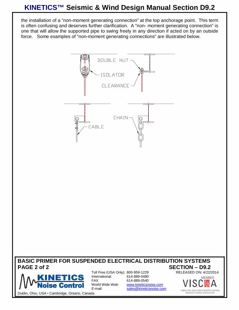
the installation of a “non-moment generating connection” at the top anchorage point. This termis often confusing and deserves further clarification. A “non- moment generating connection” isone that will allow the supported pipe to swing freely in any direction if acted on by an outsideforce. Some examples of “non-moment generating connections” are illustrated below.
KINETICS™ Seismic & Wind Design Manual Section D9.3
PROS AND CONS OF STRUTS vs CABLESPAGE 1 of 4 SECTION – D9.3
Toll Free (USA Only): 800-959-1229 RELEASED ON: 4/23/2014International: 614-889-0480FAX 614-889-0540World Wide Web: www.kineticsnoise.comE-mail: [email protected]
Dublin, Ohio, USA Cambridge, Ontario, Canada
PROS AND CONS OF STRUTS VERSUS CABLES
Both cables and struts have their place in the restraint of conduit and other electricaldistributions systems. In order to minimize costs and speed up installation, the differencesbetween the two should be understood.
In general, distribution systems restrained by struts will require only 1 brace per restraintlocation while systems restrained with cables requires that 2 cables be fitted forming an “X” ora “V”. As a trade-off, the number of restraint points needed on a given run of conduit ordistribution ducts will typically be considerably higher for a strut-restrained system than for thecable-restrained system and, generally, strut-restrained systems will be more costly to install.
An added factor to consider when selecting a restraint system is that once a decision isreached on the type to use for a particular run, code requirements state that the same type ofsystem must be used for the entire run (all cable or all strut). Later sections in this chapter willdefine runs, but for our purposes at present, it can be considered to be a more or less straightsection of piping.
The obvious advantage to struts is that, when space is at a premium, cables angling up to theceiling on each side of a run may take more space than is available. Struts can be fitted to oneside only, allowing a more narrow packaging arrangement.
The advantages of cables, where they can be used, are numerous. First, they can usually bespaced less frequently along a distribution run than can struts. Second, they cannot increasethe tensile forces in the hanger rod that results from the weight load, so rod and rod anchoragecapacities are not impacted. And third, they are easily set to the proper length.
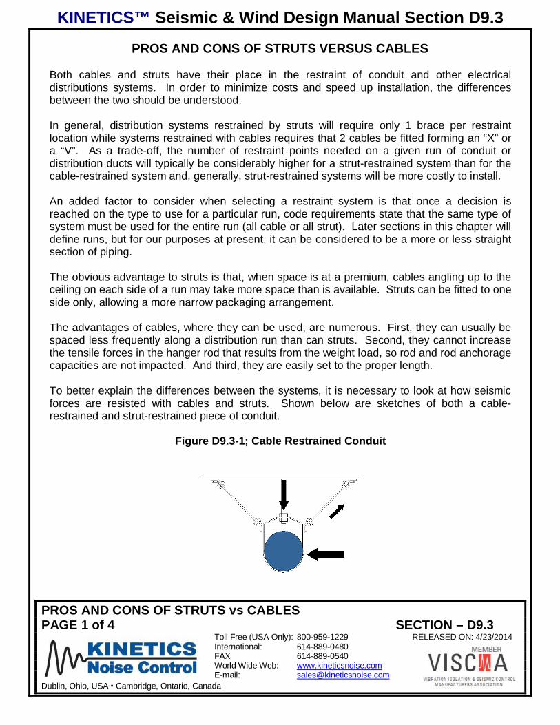
To better explain the differences between the systems, it is necessary to look at how seismicforces are resisted with cables and struts. Shown below are sketches of both a cable-restrained and strut-restrained piece of conduit.
Figure D9.3-1; Cable Restrained Conduit
KINETICS™ Seismic & Wind Design Manual Section D9.3
PROS AND CONS OF STRUTS vs CABLESPAGE 2 of 4 SECTION – D9.3
Toll Free (USA Only): 800-959-1229 RELEASED ON: 4/23/2014International: 614-889-0480FAX 614-889-0540World Wide Web: www.kineticsnoise.comE-mail: [email protected]
Dublin, Ohio, USA Cambridge, Ontario, Canada
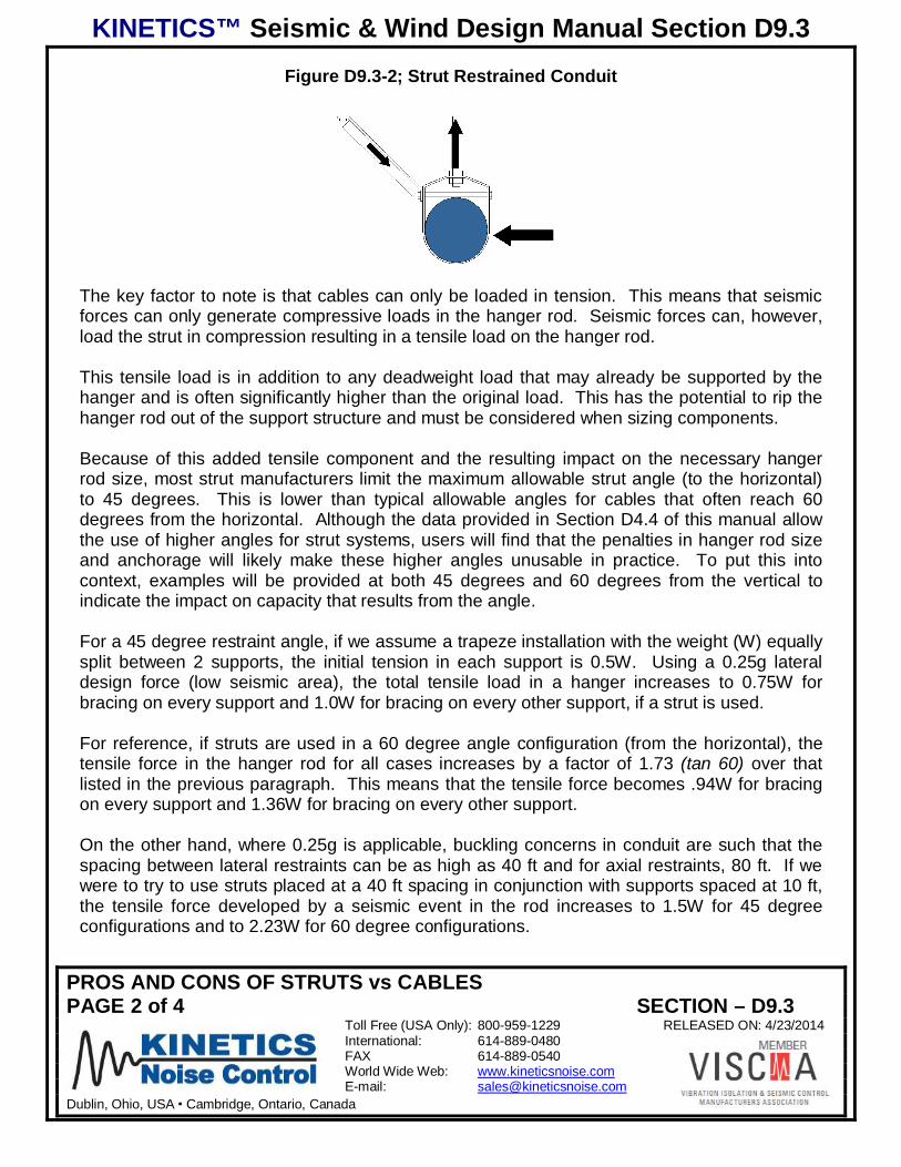
Figure D9.3-2; Strut Restrained Conduit
The key factor to note is that cables can only be loaded in tension. This means that seismicforces can only generate compressive loads in the hanger rod. Seismic forces can, however,load the strut in compression resulting in a tensile load on the hanger rod.
This tensile load is in addition to any deadweight load that may already be supported by thehanger and is often significantly higher than the original load. This has the potential to rip thehanger rod out of the support structure and must be considered when sizing components.
Because of this added tensile component and the resulting impact on the necessary hangerrod size, most strut manufacturers limit the maximum allowable strut angle (to the horizontal)to 45 degrees. This is lower than typical allowable angles for cables that often reach 60degrees from the horizontal. Although the data provided in Section D4.4 of this manual allowthe use of higher angles for strut systems, users will find that the penalties in hanger rod sizeand anchorage will likely make these higher angles unusable in practice. To put this intocontext, examples will be provided at both 45 degrees and 60 degrees from the vertical toindicate the impact on capacity that results from the angle.
For a 45 degree restraint angle, if we assume a trapeze installation with the weight (W) equallysplit between 2 supports, the initial tension in each support is 0.5W. Using a 0.25g lateraldesign force (low seismic area), the total tensile load in a hanger increases to 0.75W forbracing on every support and 1.0W for bracing on every other support, if a strut is used.
For reference, if struts are used in a 60 degree angle configuration (from the horizontal), thetensile force in the hanger rod for all cases increases by a factor of 1.73 (tan 60) over thatlisted in the previous paragraph. This means that the tensile force becomes .94W for bracingon every support and 1.36W for bracing on every other support.
On the other hand, where 0.25g is applicable, buckling concerns in conduit are such that thespacing between lateral restraints can be as high as 40 ft and for axial restraints, 80 ft. If wewere to try to use struts placed at a 40 ft spacing in conjunction with supports spaced at 10 ft,the tensile force developed by a seismic event in the rod increases to 1.5W for 45 degreeconfigurations and to 2.23W for 60 degree configurations.
KINETICS™ Seismic & Wind Design Manual Section D9.3
PROS AND CONS OF STRUTS vs CABLESPAGE 3 of 4 SECTION – D9.3
Toll Free (USA Only): 800-959-1229 RELEASED ON: 4/23/2014International: 614-889-0480FAX 614-889-0540World Wide Web: www.kineticsnoise.comE-mail: [email protected]
Dublin, Ohio, USA Cambridge, Ontario, Canada
As mentioned earlier, there is no increase in the rod forces for cable restrained systems.
Using real numbers based on a 40 ft restraint spacing and a 60 degree angle configuration, ifthe peak tensile load in the hanger rod is 500 lb for a cable restrained system, it becomes2230 lb for an otherwise identical strut restrained system.
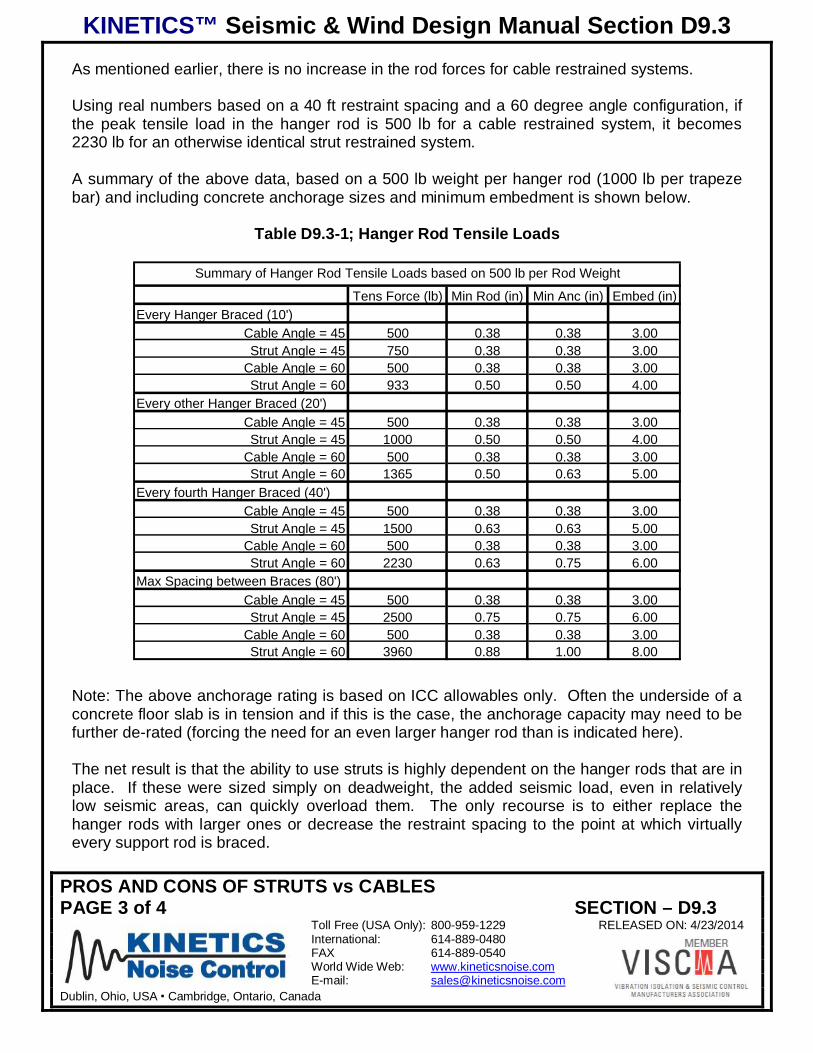
A summary of the above data, based on a 500 lb weight per hanger rod (1000 lb per trapezebar) and including concrete anchorage sizes and minimum embedment is shown below.
Table D9.3-1; Hanger Rod Tensile Loads
Summary of Hanger Rod Tensile Loads based on 500 lb per Rod Weight
Tens Force (lb) Min Rod (in) Min Anc (in) Embed (in)Every Hanger Braced (10')
Cable Angle = 45 500 0.38 0.38 3.00Strut Angle = 45 750 0.38 0.38 3.00
Cable Angle = 60 500 0.38 0.38 3.00Strut Angle = 60 933 0.50 0.50 4.00
Every other Hanger Braced (20')Cable Angle = 45 500 0.38 0.38 3.00Strut Angle = 45 1000 0.50 0.50 4.00
Cable Angle = 60 500 0.38 0.38 3.00Strut Angle = 60 1365 0.50 0.63 5.00
Every fourth Hanger Braced (40')Cable Angle = 45 500 0.38 0.38 3.00Strut Angle = 45 1500 0.63 0.63 5.00
Cable Angle = 60 500 0.38 0.38 3.00Strut Angle = 60 2230 0.63 0.75 6.00
Max Spacing between Braces (80')Cable Angle = 45 500 0.38 0.38 3.00Strut Angle = 45 2500 0.75 0.75 6.00
Cable Angle = 60 500 0.38 0.38 3.00Strut Angle = 60 3960 0.88 1.00 8.00
Note: The above anchorage rating is based on ICC allowables only. Often the underside of aconcrete floor slab is in tension and if this is the case, the anchorage capacity may need to befurther de-rated (forcing the need for an even larger hanger rod than is indicated here).
The net result is that the ability to use struts is highly dependent on the hanger rods that are inplace. If these were sized simply on deadweight, the added seismic load, even in relativelylow seismic areas, can quickly overload them. The only recourse is to either replace thehanger rods with larger ones or decrease the restraint spacing to the point at which virtuallyevery support rod is braced.
KINETICS™ Seismic & Wind Design Manual Section D9.3
PROS AND CONS OF STRUTS vs CABLESPAGE 4 of 4 SECTION – D9.3
Toll Free (USA Only): 800-959-1229 RELEASED ON: 4/23/2014International: 614-889-0480FAX 614-889-0540World Wide Web: www.kineticsnoise.comE-mail: [email protected]
Dublin, Ohio, USA Cambridge, Ontario, Canada
It should also be noted that the hanger rods in tension become seismic elements. This occurswith struts, but does not with cables. As a result, the system must comply with all of theanchor requirements specified by ICC. This includes the use of seismically rated anchors andembedment depths that are in conformance with ICC requirement for those types of anchors.With larger anchor sizes, floor slab thickness may cause this to become a significant problem.
With both cables and struts, the hanger rods can be loaded in compression. As the seismicforce increases, it eventually overcomes the force of gravity and produces a buckling load inthe hanger rod. It is mandatory in all cases that the rod be able to resist this force.
There is a wide range of variables involved in determining the need for rod stiffeners to resistthis buckling load. Factors that impact this need are 1) the magnitude of the compressiveforce, 2) the weight load carried by the hanger rod, 3) the length of the hanger rod, 4) thediameter of the hanger rod, and 5) the angle between the restraint strut or cable and thehorizontal axis.
Charts are included in Section D4.4 of this manual that allow the user to determine if there is aneed for a stiffener and to allow the proper selection if required.
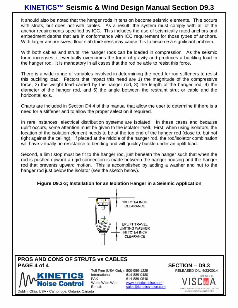
In rare instances, electrical distribution systems are isolated. In these cases and becauseuplift occurs, some attention must be given to the isolator itself. First, when using isolators, thelocation of the isolation element needs to be at the top end of the hanger rod (close to, but nottight against the ceiling). If placed at the middle of the hanger rod, the rod/isolator combinationwill have virtually no resistance to bending and will quickly buckle under an uplift load.
Second, a limit stop must be fit to the hanger rod, just beneath the hanger such that when therod is pushed upward a rigid connection is made between the hanger housing and the hangerrod that prevents upward motion. This is accomplished by adding a washer and nut to thehanger rod just below the isolator (see the sketch below).
Figure D9.3-3; Installation for an Isolation Hanger in a Seismic Application
KINETICS™ Seismic & Wind Design Manual Section D9.4.1
ELECTRICAL RESTRAINTS-DEFINITIONS AND LOCATING REQUIREMENTSPAGE 1 of 7 SECTION – D9.4.1
Toll Free (USA Only): 800-959-1229 RELEASED ON: 4/22/2014International: 614-889-0480FAX 614-889-0540World Wide Web: www.kineticsnoise.comE-mail: [email protected]
Dublin, Ohio, USA Cambridge, Ontario, Canada
REQUIREMENTS FOR DISTRIBUTION SYSTEM RESTRAINTSDEFINITIONS AND LOCATING REQUIREMENTS
There are a number of design guides that have been developed over the years but the onewith the longest history and most widely accepted is SMACNA. They have developed ahandbook that offers conservative guidance that an end user can reference in selecting andinstalling restraints for distribution systems. While the information provided in that handbook isgood, it suffers from a couple of inherent drawbacks. The first is that because it is linked togenerically available hardware, the ratings that are assumed for the various hardwarecomponents are the lowest of any of the many possibilities available in the marketplace. Thenet result is that the suggested hardware is larger in general than that which could be used ifhigher quality componentry it specified. The second is that their presentation of the results isextremely cumbersome and difficult to use.
While the criteria presented in this document is based on the guidance offered by SMACNA, ithas been possible to increase the component ratings as the actual capacity, type andmanufacture of these components is clearly known. In addition, based on a critical review ofthe data presentation in the SMACNA handbook, it has been possible to greatly simplify themethod of selection making the end result much simpler to use.
With respect to the conceptual restraint arrangement illustrations, the SMACNA concepts areappropriate and are referenced here.
In general, conduit and other components used for electrical distribution are restrained inlengths called “runs.” Therefore before getting into a detailed review of the restraint systems itis imperative that a definition of “run” as well as other key terms be addressed.
D9.4.1-1 Definitions
Axial In the direction of the axis of the run.
Lateral Side to side when looking along the axis of the run.
Pipe or Conduit Clamp A heavy duty split ring clamp tightened against the conduit to thepoint that it can be used to control the axial motion of the conduit, tray or duct.
Restraint Any device that limits the motion of a conduit or duct in either the lateral or axialdirection.
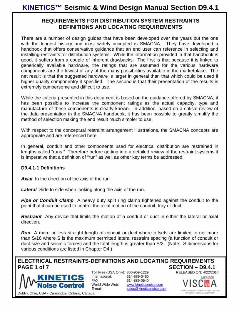
Run A more or less straight length of conduit or duct where offsets are limited to not morethan S/16 where S is the maximum permitted lateral restraint spacing (a function of conduit orduct size and seismic forces) and the total length is greater than S/2. (Note: S dimensions forvarious conditions are listed in Chapter D4.)
KINETICS™ Seismic & Wind Design Manual Section D9.4.1
ELECTRICAL RESTRAINTS-DEFINITIONS AND LOCATING REQUIREMENTSPAGE 2 of 7 SECTION – D9.4.1
Toll Free (USA Only): 800-959-1229 RELEASED ON: 4/22/2014International: 614-889-0480FAX 614-889-0540World Wide Web: www.kineticsnoise.comE-mail: [email protected]
Dublin, Ohio, USA Cambridge, Ontario, Canada
Figure D9.4.1-1; Definition of a “Run” of Duct
Short Run A run as defined above where the total length is less than S/2 and where it isconnected on both ends to other runs or short runs.
Drop A length of conduit that normally extends down from an overhead distribution systemand connects to a piece of equipment, usually through some type of flex connector. The dropcan also extend horizontally. In order to qualify as a drop, the length of this conduit must beless than S/2. If over S/2, the length of conduit would be classified as a run.
Figure D9.4.1-2; Definition of a “Drop”
KINETICS™ Seismic & Wind Design Manual Section D9.4.1
ELECTRICAL RESTRAINTS-DEFINITIONS AND LOCATING REQUIREMENTSPAGE 3 of 7 SECTION – D9.4.1
Toll Free (USA Only): 800-959-1229 RELEASED ON: 4/22/2014International: 614-889-0480FAX 614-889-0540World Wide Web: www.kineticsnoise.comE-mail: [email protected]
Dublin, Ohio, USA Cambridge, Ontario, Canada
D9.4.1-2 Restraint Requirements
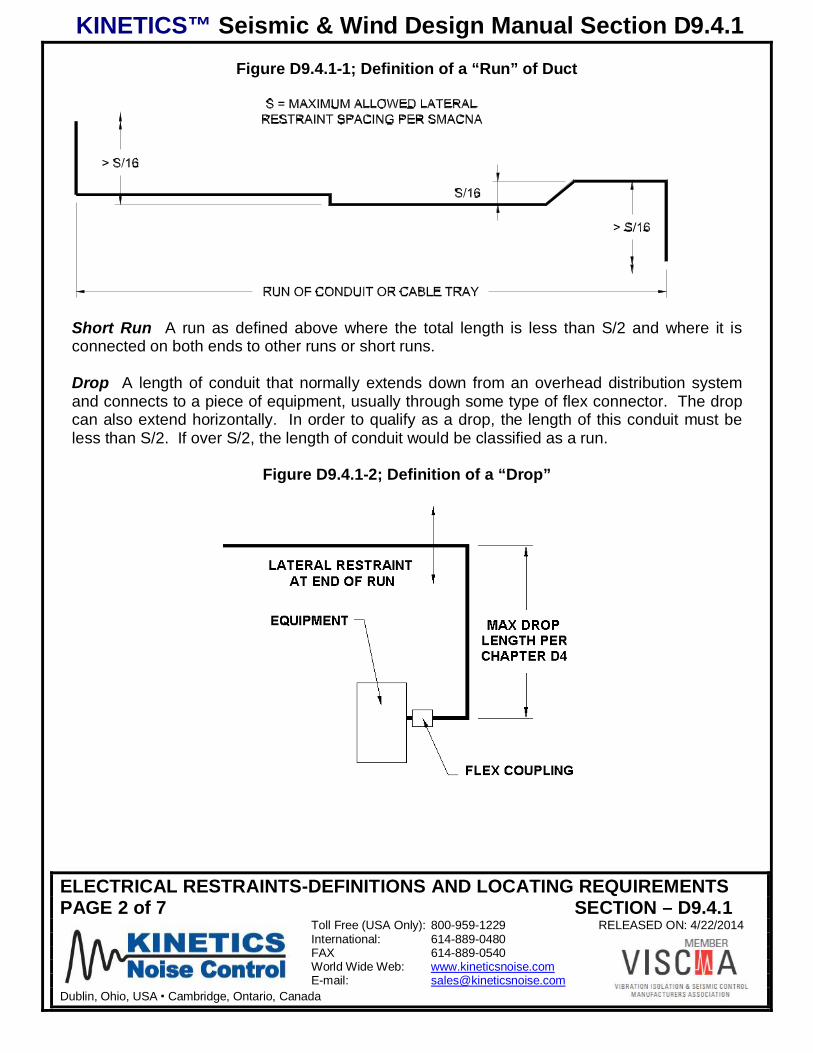
1) Full runs greater in length than S/2) must be restrained in both the axial and lateraldirection. If the run is not a short run or a drop, it must, as a minimum, be laterallyrestrained at the last support location on each end.
Figure D9.4.1-2; Basic Restraint Requirements for a Typical “Run” of Conduit
2) If a run is longer than “S”, intermediate restraints are required to limit the spacing to thatpermitted by the building code (see table in Chapter D4).
Figure D9.4.1-3; Basic Restraint Requirements for a Long “Run” of Conduit
3) Axial restraints attached to the run of conduit along its length must be connected using aconduit clamp (as previously defined).
4) Short runs or drops need only have one lateral and one axial restraint.
KINETICS™ Seismic & Wind Design Manual Section D9.4.1
ELECTRICAL RESTRAINTS-DEFINITIONS AND LOCATING REQUIREMENTSPAGE 4 of 7 SECTION – D9.4.1
Toll Free (USA Only): 800-959-1229 RELEASED ON: 4/22/2014International: 614-889-0480FAX 614-889-0540World Wide Web: www.kineticsnoise.comE-mail: [email protected]
Dublin, Ohio, USA Cambridge, Ontario, Canada
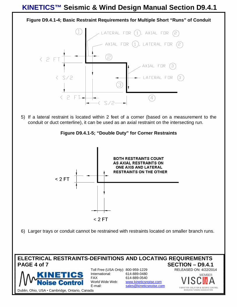
Figure D9.4.1-4; Basic Restraint Requirements for Multiple Short “Runs” of Conduit
5) If a lateral restraint is located within 2 feet of a corner (based on a measurement to theconduit or duct centerline), it can be used as an axial restraint on the intersecting run.
Figure D9.4.1-5; “Double Duty” for Corner Restraints
6) Larger trays or conduit cannot be restrained with restraints located on smaller branch runs.
KINETICS™ Seismic & Wind Design Manual Section D9.4.1
ELECTRICAL RESTRAINTS-DEFINITIONS AND LOCATING REQUIREMENTSPAGE 5 of 7 SECTION – D9.4.1
Toll Free (USA Only): 800-959-1229 RELEASED ON: 4/22/2014International: 614-889-0480FAX 614-889-0540World Wide Web: www.kineticsnoise.comE-mail: [email protected]
Dublin, Ohio, USA Cambridge, Ontario, Canada
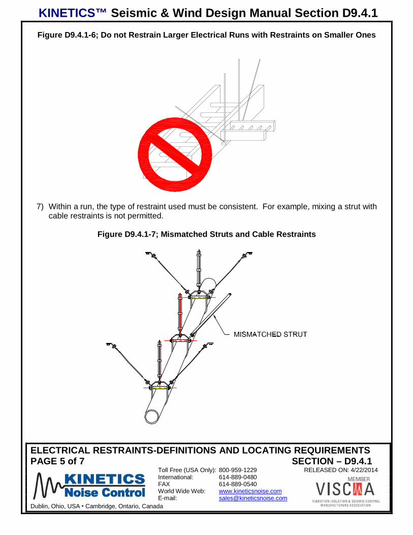
Figure D9.4.1-6; Do not Restrain Larger Electrical Runs with Restraints on Smaller Ones
7) Within a run, the type of restraint used must be consistent. For example, mixing a strut withcable restraints is not permitted.
Figure D9.4.1-7; Mismatched Struts and Cable Restraints
KINETICS™ Seismic & Wind Design Manual Section D9.4.1
ELECTRICAL RESTRAINTS-DEFINITIONS AND LOCATING REQUIREMENTSPAGE 6 of 7 SECTION – D9.4.1
Toll Free (USA Only): 800-959-1229 RELEASED ON: 4/22/2014International: 614-889-0480FAX 614-889-0540World Wide Web: www.kineticsnoise.comE-mail: [email protected]
Dublin, Ohio, USA Cambridge, Ontario, Canada
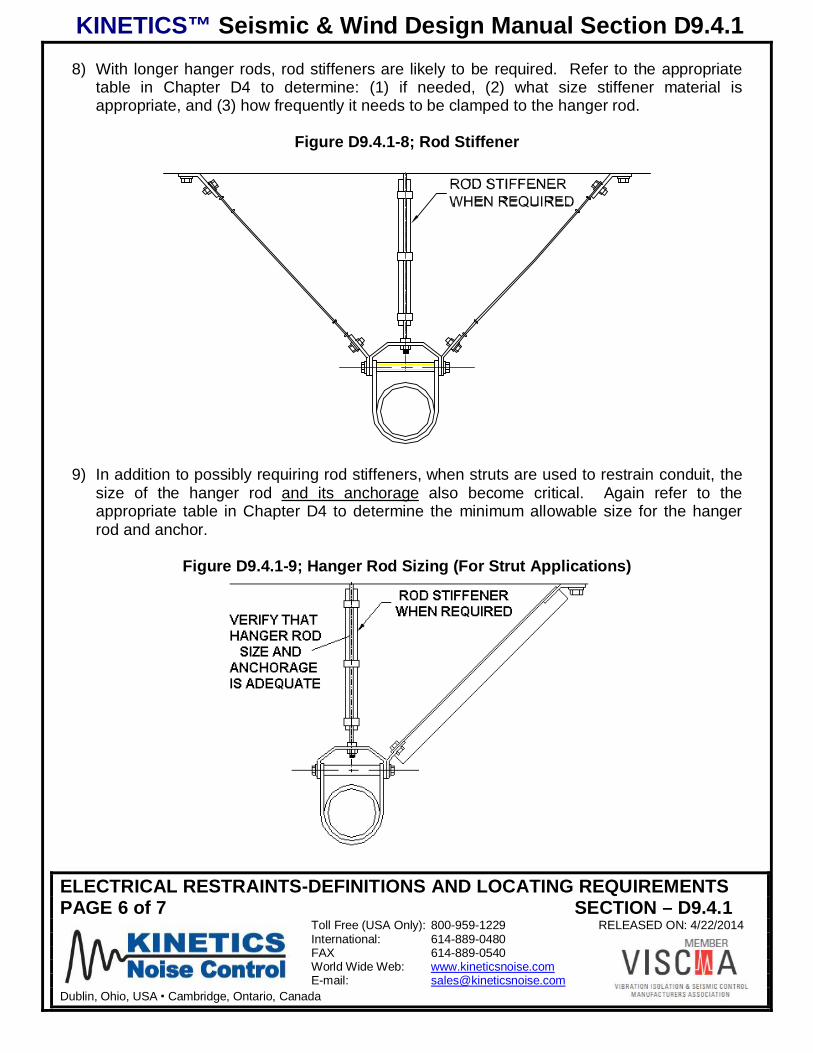
8) With longer hanger rods, rod stiffeners are likely to be required. Refer to the appropriatetable in Chapter D4 to determine: (1) if needed, (2) what size stiffener material isappropriate, and (3) how frequently it needs to be clamped to the hanger rod.
Figure D9.4.1-8; Rod Stiffener
9) In addition to possibly requiring rod stiffeners, when struts are used to restrain conduit, thesize of the hanger rod and its anchorage also become critical. Again refer to theappropriate table in Chapter D4 to determine the minimum allowable size for the hangerrod and anchor.
Figure D9.4.1-9; Hanger Rod Sizing (For Strut Applications)
KINETICS™ Seismic & Wind Design Manual Section D9.4.1
ELECTRICAL RESTRAINTS-DEFINITIONS AND LOCATING REQUIREMENTSPAGE 7 of 7 SECTION – D9.4.1
Toll Free (USA Only): 800-959-1229 RELEASED ON: 4/22/2014International: 614-889-0480FAX 614-889-0540World Wide Web: www.kineticsnoise.comE-mail: [email protected]
Dublin, Ohio, USA Cambridge, Ontario, Canada
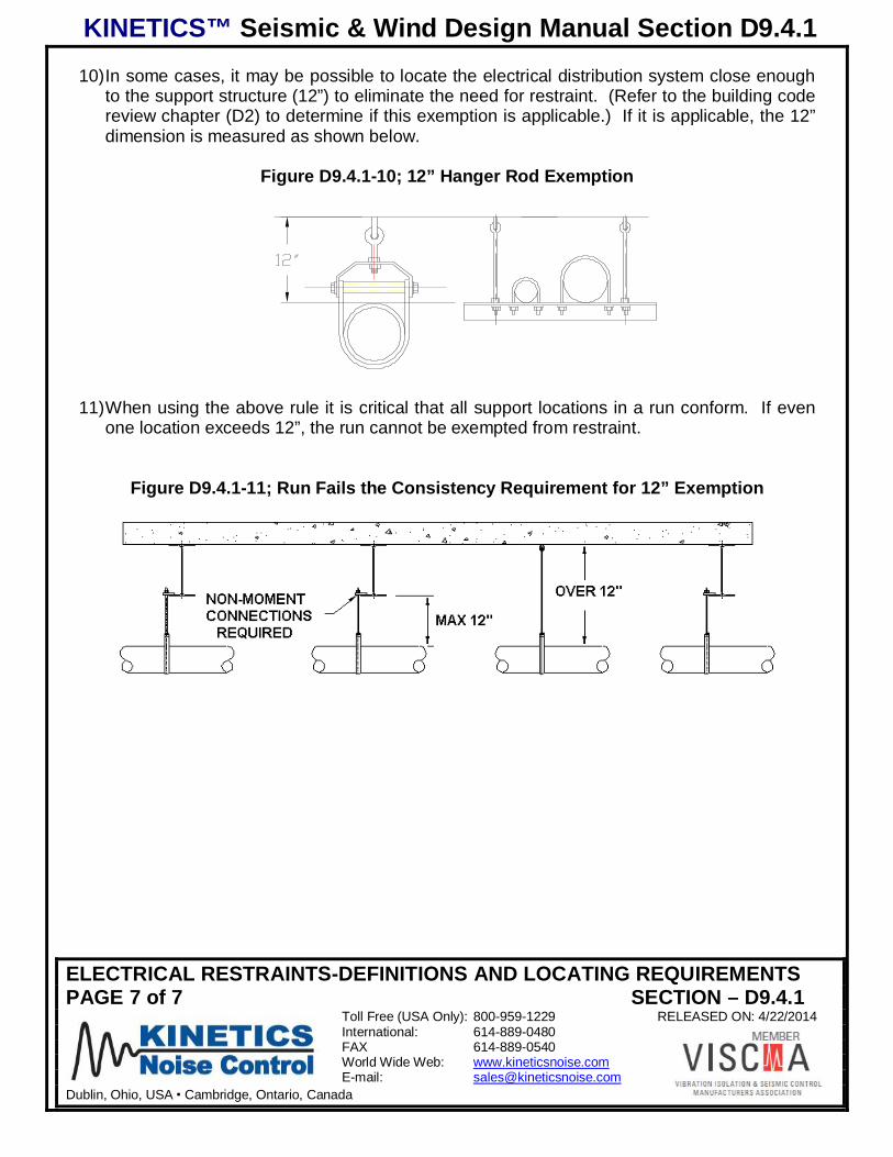
10) In some cases, it may be possible to locate the electrical distribution system close enoughto the support structure (12”) to eliminate the need for restraint. (Refer to the building codereview chapter (D2) to determine if this exemption is applicable.) If it is applicable, the 12”dimension is measured as shown below.
Figure D9.4.1-10; 12” Hanger Rod Exemption
11) When using the above rule it is critical that all support locations in a run conform. If evenone location exceeds 12”, the run cannot be exempted from restraint.
Figure D9.4.1-11; Run Fails the Consistency Requirement for 12” Exemption
KINETICS™ Seismic & Wind Design Manual Section D9.4.2
CEILING SUPPORTED ELECTRICAL RESTRAINT ARRANGEMENTSPAGE 1 of 6 SECTION – D9.4.2
Toll Free (USA Only): 800-959-1229 RELEASED ON: 4/22/2014International: 614-889-0480FAX 614-889-0540World Wide Web: www.kineticsnoise.comE-mail: [email protected]
Dublin, Ohio, USA Cambridge, Ontario, Canada
CEILING-SUPPORTED ELECTRICAL DISTRIBUTION SYSTEM RESTRAINTARRANGEMENTS
Although the basic principle of diagonal bracing is almost always used to design restraintsystems, the actual arrangement of these systems can vary significantly. Despite what lookslike substantially different designs, the design forces in the members remain the same, and thesame rules apply when sizing components. Illustrated here are many different restraintarrangements, all of which can be used in conjunction with the design “rules” provided in thismanual.
It is assumed in this section that all conduit is rigid. For non-rigid conduit and if the conduit islarge enough to require restraint, adequate hardware to accomplish this task is required ateach support location.
Details of the end connections and anchorage hardware are shown in subsequent sections ofthe manual. It is assumed in this manual that the restraint component is attached to astructural element capable of resisting the design seismic load.
Due to variations in the installation conditions such as structural clearance, locations ofstructural attachment points, and interference with other pieces of equipment or systems, therewill likely be significant benefits to using different arrangements in different locations on thesame job.
The only significant caution here is that it is not permissible to mix struts and cables on thesame run.
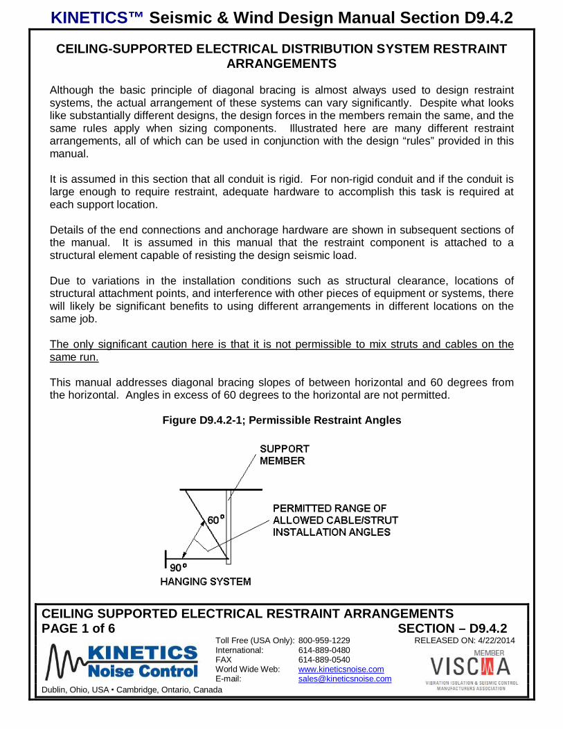
This manual addresses diagonal bracing slopes of between horizontal and 60 degrees fromthe horizontal. Angles in excess of 60 degrees to the horizontal are not permitted.
Figure D9.4.2-1; Permissible Restraint Angles
KINETICS™ Seismic & Wind Design Manual Section D9.4.2
CEILING SUPPORTED ELECTRICAL RESTRAINT ARRANGEMENTSPAGE 2 of 6 SECTION – D9.4.2
Toll Free (USA Only): 800-959-1229 RELEASED ON: 4/22/2014International: 614-889-0480FAX 614-889-0540World Wide Web: www.kineticsnoise.comE-mail: [email protected]
Dublin, Ohio, USA Cambridge, Ontario, Canada
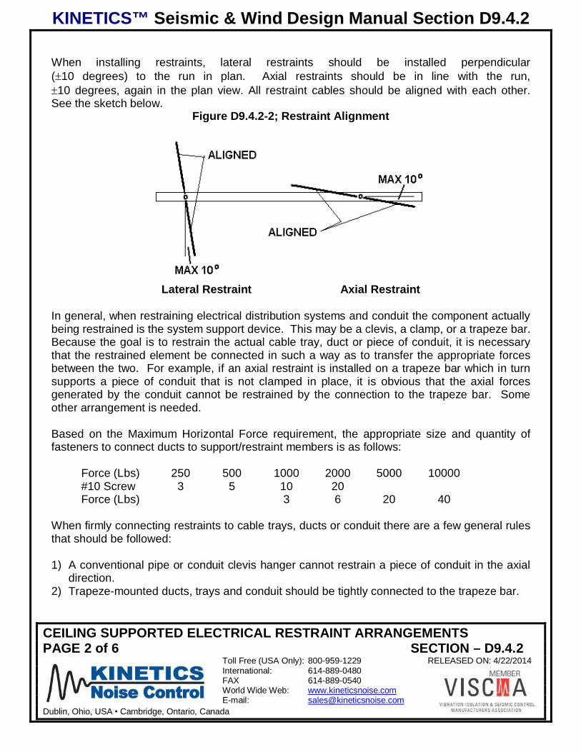
When installing restraints, lateral restraints should be installed perpendicular( 10 degrees) to the run in plan. Axial restraints should be in line with the run,10 degrees, again in the plan view. All restraint cables should be aligned with each other.
See the sketch below.Figure D9.4.2-2; Restraint Alignment
Lateral Restraint Axial Restraint
In general, when restraining electrical distribution systems and conduit the component actuallybeing restrained is the system support device. This may be a clevis, a clamp, or a trapeze bar.Because the goal is to restrain the actual cable tray, duct or piece of conduit, it is necessarythat the restrained element be connected in such a way as to transfer the appropriate forcesbetween the two. For example, if an axial restraint is installed on a trapeze bar which in turnsupports a piece of conduit that is not clamped in place, it is obvious that the axial forcesgenerated by the conduit cannot be restrained by the connection to the trapeze bar. Someother arrangement is needed.
Based on the Maximum Horizontal Force requirement, the appropriate size and quantity offasteners to connect ducts to support/restraint members is as follows:
Force (Lbs) 250 500 1000 2000 5000 10000#10 Screw 3 5 10 20Force (Lbs) 3 6 20 40
When firmly connecting restraints to cable trays, ducts or conduit there are a few general rulesthat should be followed:
1) A conventional pipe or conduit clevis hanger cannot restrain a piece of conduit in the axialdirection.
2) Trapeze-mounted ducts, trays and conduit should be tightly connected to the trapeze bar.
KINETICS™ Seismic & Wind Design Manual Section D9.4.2
CEILING SUPPORTED ELECTRICAL RESTRAINT ARRANGEMENTSPAGE 3 of 6 SECTION – D9.4.2
Toll Free (USA Only): 800-959-1229 RELEASED ON: 4/22/2014International: 614-889-0480FAX 614-889-0540World Wide Web: www.kineticsnoise.comE-mail: [email protected]
Dublin, Ohio, USA Cambridge, Ontario, Canada
3) If a tray or duct is used and it is mounted with the long dimension in the horizontal plane,the maximum spacing for restraints should be based on the allowable spacing for a pipe ofa diameter equal to the tray’s long axis dimension.
4) If a tray or duct is used and it is mounted with the short dimension in the horizontal plane,the maximum spacing for restraints should be based on the allowable spacing for a pipe ofa diameter equal to the tray’s short axis dimension.
In addition, when sizing restraint components for multiple pieces of conduit, the total weight ofall the restrained conduit must be considered.
D9.4.2.1 Hanging Systems Restrained with Cables
Hanging systems may include supports for single or multiple conduit runs, buss ducts or cabletrays. Single conduit runs can be supported using clevis hangers but wherever multiple itemsare used, they are normally supported on trapeze bars.
Lateral Restraint Examples
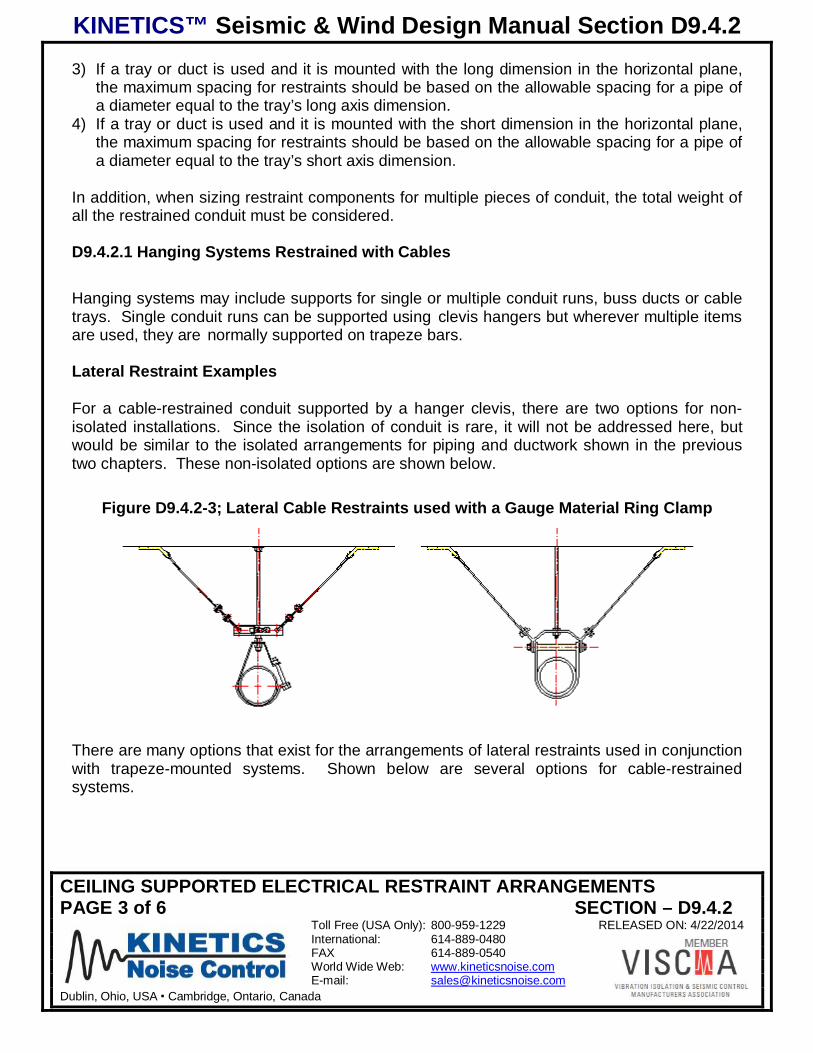
For a cable-restrained conduit supported by a hanger clevis, there are two options for non-isolated installations. Since the isolation of conduit is rare, it will not be addressed here, butwould be similar to the isolated arrangements for piping and ductwork shown in the previoustwo chapters. These non-isolated options are shown below.
Figure D9.4.2-3; Lateral Cable Restraints used with a Gauge Material Ring Clamp
There are many options that exist for the arrangements of lateral restraints used in conjunctionwith trapeze-mounted systems. Shown below are several options for cable-restrainedsystems.
KINETICS™ Seismic & Wind Design Manual Section D9.4.2
CEILING SUPPORTED ELECTRICAL RESTRAINT ARRANGEMENTSPAGE 4 of 6 SECTION – D9.4.2
Toll Free (USA Only): 800-959-1229 RELEASED ON: 4/22/2014International: 614-889-0480FAX 614-889-0540World Wide Web: www.kineticsnoise.comE-mail: [email protected]
Dublin, Ohio, USA Cambridge, Ontario, Canada
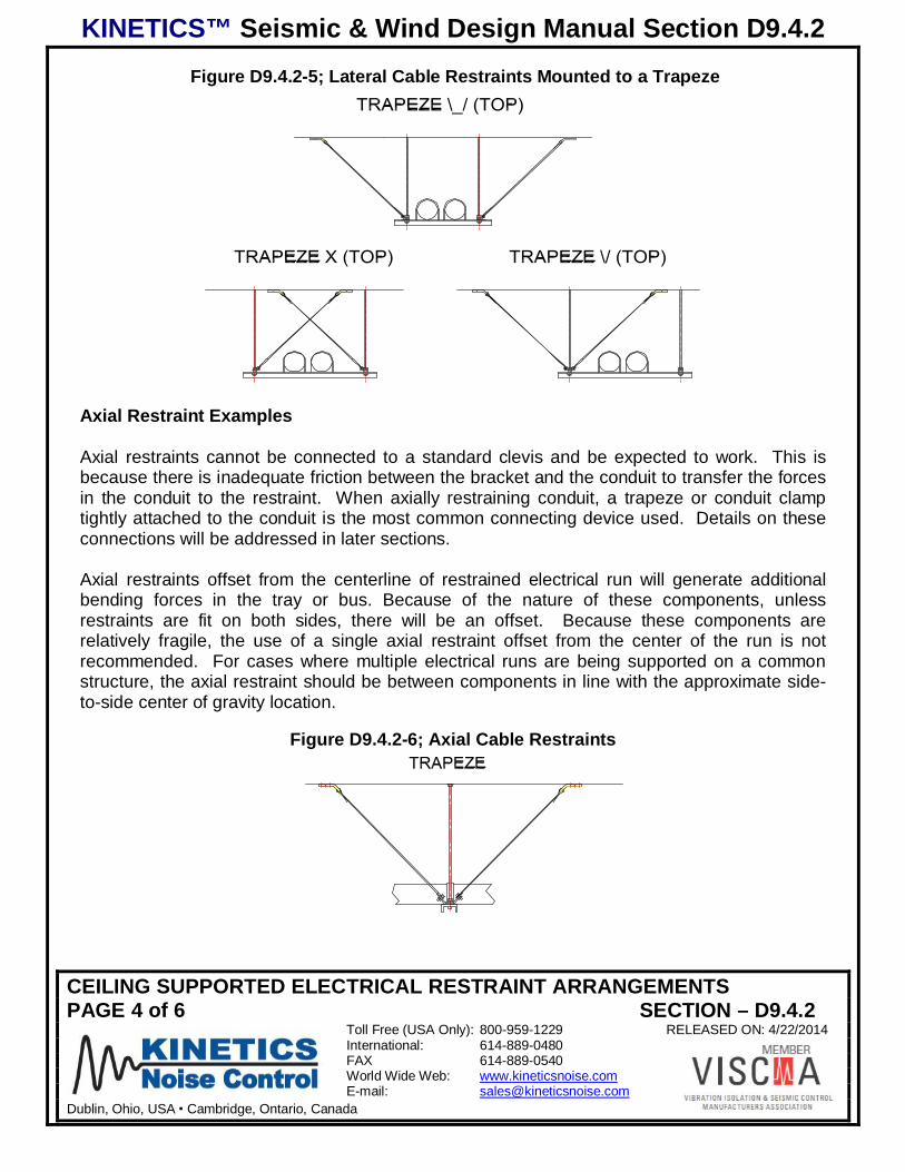
Figure D9.4.2-5; Lateral Cable Restraints Mounted to a Trapeze
Axial Restraint Examples
Axial restraints cannot be connected to a standard clevis and be expected to work. This isbecause there is inadequate friction between the bracket and the conduit to transfer the forcesin the conduit to the restraint. When axially restraining conduit, a trapeze or conduit clamptightly attached to the conduit is the most common connecting device used. Details on theseconnections will be addressed in later sections.
Axial restraints offset from the centerline of restrained electrical run will generate additionalbending forces in the tray or bus. Because of the nature of these components, unlessrestraints are fit on both sides, there will be an offset. Because these components arerelatively fragile, the use of a single axial restraint offset from the center of the run is notrecommended. For cases where multiple electrical runs are being supported on a commonstructure, the axial restraint should be between components in line with the approximate side-to-side center of gravity location.
Figure D9.4.2-6; Axial Cable Restraints
KINETICS™ Seismic & Wind Design Manual Section D9.4.2
CEILING SUPPORTED ELECTRICAL RESTRAINT ARRANGEMENTSPAGE 5 of 6 SECTION – D9.4.2
Toll Free (USA Only): 800-959-1229 RELEASED ON: 4/22/2014International: 614-889-0480FAX 614-889-0540World Wide Web: www.kineticsnoise.comE-mail: [email protected]
Dublin, Ohio, USA Cambridge, Ontario, Canada
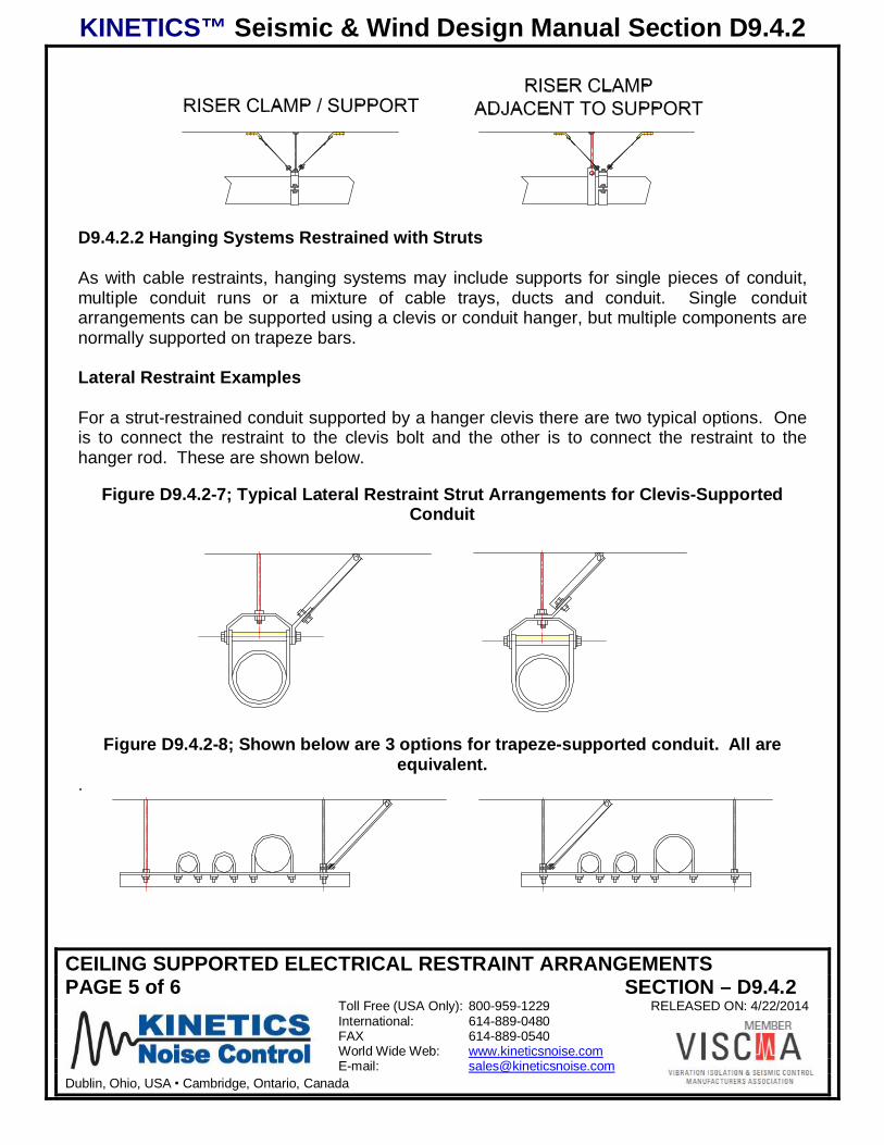
D9.4.2.2 Hanging Systems Restrained with Struts
As with cable restraints, hanging systems may include supports for single pieces of conduit,multiple conduit runs or a mixture of cable trays, ducts and conduit. Single conduitarrangements can be supported using a clevis or conduit hanger, but multiple components arenormally supported on trapeze bars.
Lateral Restraint Examples
For a strut-restrained conduit supported by a hanger clevis there are two typical options. Oneis to connect the restraint to the clevis bolt and the other is to connect the restraint to thehanger rod. These are shown below.
Figure D9.4.2-7; Typical Lateral Restraint Strut Arrangements for Clevis-SupportedConduit
Figure D9.4.2-8; Shown below are 3 options for trapeze-supported conduit. All areequivalent.
.
KINETICS™ Seismic & Wind Design Manual Section D9.4.2
CEILING SUPPORTED ELECTRICAL RESTRAINT ARRANGEMENTSPAGE 6 of 6 SECTION – D9.4.2
Toll Free (USA Only): 800-959-1229 RELEASED ON: 4/22/2014International: 614-889-0480FAX 614-889-0540World Wide Web: www.kineticsnoise.comE-mail: [email protected]
Dublin, Ohio, USA Cambridge, Ontario, Canada
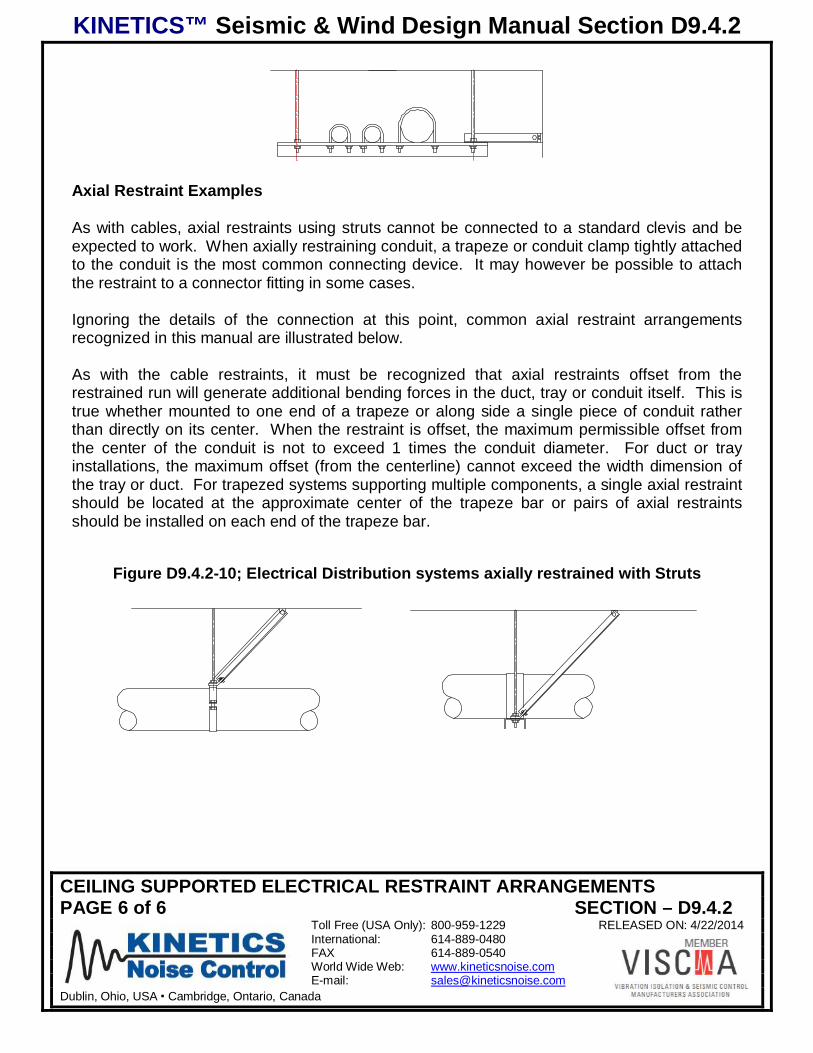
Axial Restraint Examples
As with cables, axial restraints using struts cannot be connected to a standard clevis and beexpected to work. When axially restraining conduit, a trapeze or conduit clamp tightly attachedto the conduit is the most common connecting device. It may however be possible to attachthe restraint to a connector fitting in some cases.
Ignoring the details of the connection at this point, common axial restraint arrangementsrecognized in this manual are illustrated below.
As with the cable restraints, it must be recognized that axial restraints offset from therestrained run will generate additional bending forces in the duct, tray or conduit itself. This istrue whether mounted to one end of a trapeze or along side a single piece of conduit ratherthan directly on its center. When the restraint is offset, the maximum permissible offset fromthe center of the conduit is not to exceed 1 times the conduit diameter. For duct or trayinstallations, the maximum offset (from the centerline) cannot exceed the width dimension ofthe tray or duct. For trapezed systems supporting multiple components, a single axial restraintshould be located at the approximate center of the trapeze bar or pairs of axial restraintsshould be installed on each end of the trapeze bar.
Figure D9.4.2-10; Electrical Distribution systems axially restrained with Struts
KINETICS™ Seismic & Wind Design Manual Section D9.4.3
FLOOR- OR ROOF-SUPPORTED ELECTRIVAL RESTRAINT ARRANGEMENTSPAGE 1 of 5 SECTION – D9.4.3
Toll Free (USA Only): 800-959-1229 RELEASED ON: 4/22/2014International: 614-889-0480FAX 614-889-0540World Wide Web: www.kineticsnoise.comE-mail: [email protected]
Dublin, Ohio, USA Cambridge, Ontario, Canada
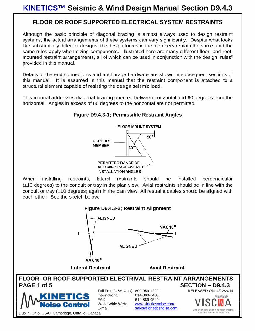
FLOOR OR ROOF SUPPORTED ELECTRICAL SYSTEM RESTRAINTS
Although the basic principle of diagonal bracing is almost always used to design restraintsystems, the actual arrangements of these systems can vary significantly. Despite what lookslike substantially different designs, the design forces in the members remain the same, and thesame rules apply when sizing components. Illustrated here are many different floor- and roof-mounted restraint arrangements, all of which can be used in conjunction with the design “rules”provided in this manual.
Details of the end connections and anchorage hardware are shown in subsequent sections ofthis manual. It is assumed in this manual that the restraint component is attached to astructural element capable of resisting the design seismic load.
This manual addresses diagonal bracing oriented between horizontal and 60 degrees from thehorizontal. Angles in excess of 60 degrees to the horizontal are not permitted.
Figure D9.4.3-1; Permissible Restraint Angles
When installing restraints, lateral restraints should be installed perpendicular( 10 degrees) to the conduit or tray in the plan view. Axial restraints should be in line with theconduit or tray ( 10 degrees) again in the plan view. All restraint cables should be aligned witheach other. See the sketch below.
Figure D9.4.3-2; Restraint Alignment
Lateral Restraint Axial Restraint
KINETICS™ Seismic & Wind Design Manual Section D9.4.3
FLOOR- OR ROOF-SUPPORTED ELECTRIVAL RESTRAINT ARRANGEMENTSPAGE 2 of 5 SECTION – D9.4.3
Toll Free (USA Only): 800-959-1229 RELEASED ON: 4/22/2014International: 614-889-0480FAX 614-889-0540World Wide Web: www.kineticsnoise.comE-mail: [email protected]
Dublin, Ohio, USA Cambridge, Ontario, Canada
In general, when restraining conduit or trays, the component actually being restrained is thesupport device for the system. For floor-mounted equipment this would normally be either afabricated frame or a trapeze bar. Because the goal is to restrain the actual conduit or tray, itis necessary that the restrained element be connected to the conduit or tray in such a way asto transfer the appropriate forces between the two. For example, if an axial restraint isinstalled on a trapeze bar which in turn supports a conduit or tray that is not clamped tightly toit, it is obvious that the axial forces generated by the conduit or tray cannot be restrained bythe connection to the trapeze bar and some other arrangement is needed.
With respect to firmly connecting restraints to conduit or tray, there are a few general rules thatshould be followed:
1) For Axial restraints, conduit clamps must be heavy duty and must be tightly clampedagainst the conduit itself.
2) If the pipe is wrapped or covered with a material that can reduce the clamps ability to grip it,the material must be removed or hardened to the point that positive clamping action can beassured.
3) Trapeze-mounted conduit or trays should be tightly clamped or bolted to the trapeze bar.
In addition, when sizing restraint components that affect multiple components, the total weightof all of the restrained componentry must be considered.
D9.4.3.1 Floor or Roof mounted Systems Restrained with Cables
Floor- or roof-mounted systems may include supports for single runs of conduit, multiple runs,cable trays or bus ducts. Typically, simple box frames are fabricated to support these, nomatter what they are.
Transverse Restraint Examples
For a cable-restrained support brackets there are four options normally encountered for non-isolated systems. As Electrical distribution systems are rarely isolated, for the purposes of thisdocument, isolated systems will not be addressed. These options are shown below. Thevertical legs of the support bracket must be sized to carry both the weight load of thesupported pipes as well as the vertical component of the seismic forces. Refer to Chapter D4for more detailed information as to how to size these members.
KINETICS™ Seismic & Wind Design Manual Section D9.4.3
FLOOR- OR ROOF-SUPPORTED ELECTRIVAL RESTRAINT ARRANGEMENTSPAGE 3 of 5 SECTION – D9.4.3
Toll Free (USA Only): 800-959-1229 RELEASED ON: 4/22/2014International: 614-889-0480FAX 614-889-0540World Wide Web: www.kineticsnoise.comE-mail: [email protected]
Dublin, Ohio, USA Cambridge, Ontario, Canada
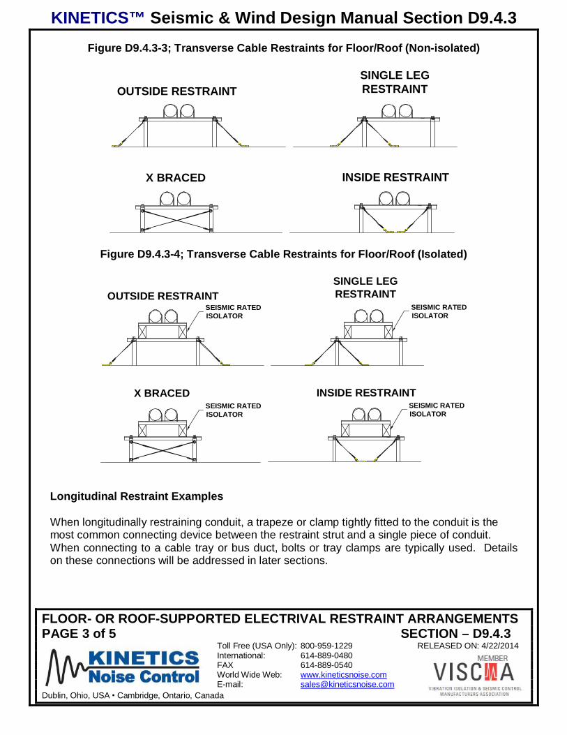
Figure D9.4.3-3; Transverse Cable Restraints for Floor/Roof (Non-isolated)
OUTSIDE RESTRAINTSINGLE LEGRESTRAINT
INSIDE RESTRAINTX BRACED
Figure D9.4.3-4; Transverse Cable Restraints for Floor/Roof (Isolated)
OUTSIDE RESTRAINT
X BRACED INSIDE RESTRAINT
SINGLE LEGRESTRAINT
SEISMIC RATEDISOLATOR
SEISMIC RATEDISOLATOR
SEISMIC RATEDISOLATOR
SEISMIC RATEDISOLATOR
Longitudinal Restraint Examples
When longitudinally restraining conduit, a trapeze or clamp tightly fitted to the conduit is themost common connecting device between the restraint strut and a single piece of conduit.When connecting to a cable tray or bus duct, bolts or tray clamps are typically used. Detailson these connections will be addressed in later sections.
KINETICS™ Seismic & Wind Design Manual Section D9.4.3
FLOOR- OR ROOF-SUPPORTED ELECTRIVAL RESTRAINT ARRANGEMENTSPAGE 4 of 5 SECTION – D9.4.3
Toll Free (USA Only): 800-959-1229 RELEASED ON: 4/22/2014International: 614-889-0480FAX 614-889-0540World Wide Web: www.kineticsnoise.comE-mail: [email protected]
Dublin, Ohio, USA Cambridge, Ontario, Canada
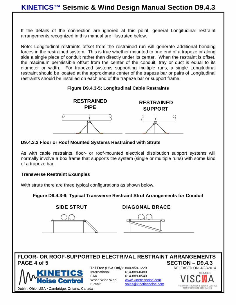
If the details of the connection are ignored at this point, general Longitudinal restraintarrangements recognized in this manual are illustrated below.
Note: Longitudinal restraints offset from the restrained run will generate additional bendingforces in the restrained system. This is true whether mounted to one end of a trapeze or alongside a single piece of conduit rather than directly under its center. When the restraint is offset,the maximum permissible offset from the center of the conduit, tray or duct is equal to itsdiameter or width. For trapezed systems supporting multiple runs, a single Longitudinalrestraint should be located at the approximate center of the trapeze bar or pairs of Longitudinalrestraints should be installed on each end of the trapeze bar or support frame.
Figure D9.4.3-5; Longitudinal Cable Restraints
RESTRAINEDSUPPORT
RESTRAINEDPIPE
D9.4.3.2 Floor or Roof Mounted Systems Restrained with Struts
As with cable restraints, floor- or roof-mounted electrical distribution support systems willnormally involve a box frame that supports the system (single or multiple runs) with some kindof a trapeze bar.
Transverse Restraint Examples
With struts there are three typical configurations as shown below.
Figure D9.4.3-6; Typical Transverse Restraint Strut Arrangements for Conduit
SIDE STRUT DIAGONAL BRACE
KINETICS™ Seismic & Wind Design Manual Section D9.4.3
FLOOR- OR ROOF-SUPPORTED ELECTRIVAL RESTRAINT ARRANGEMENTSPAGE 5 of 5 SECTION – D9.4.3
Toll Free (USA Only): 800-959-1229 RELEASED ON: 4/22/2014International: 614-889-0480FAX 614-889-0540World Wide Web: www.kineticsnoise.comE-mail: [email protected]
Dublin, Ohio, USA Cambridge, Ontario, Canada
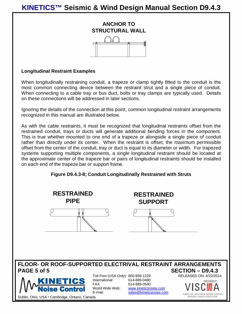
ANCHOR TOSTRUCTURAL WALL
Longitudinal Restraint Examples
When longitudinally restraining conduit, a trapeze or clamp tightly fitted to the conduit is themost common connecting device between the restraint strut and a single piece of conduit.When connecting to a cable tray or bus duct, bolts or tray clamps are typically used. Detailson these connections will be addressed in later sections.
Ignoring the details of the connection at this point, common longitudinal restraint arrangementsrecognized in this manual are illustrated below.
As with the cable restraints, it must be recognized that longitudinal restraints offset from therestrained conduit, trays or ducts will generate additional bending forces in the component.This is true whether mounted to one end of a trapeze or alongside a single piece of conduitrather than directly under its center. When the restraint is offset, the maximum permissibleoffset from the center of the conduit, tray or duct is equal to its diameter or width. For trapezedsystems supporting multiple components, a single longitudinal restraint should be located atthe approximate center of the trapeze bar or pairs of longitudinal restraints should be installedon each end of the trapeze bar or support frame.
Figure D9.4.3-8; Conduit Longitudinally Restrained with Struts
RESTRAINEDSUPPORT
RESTRAINEDPIPE
KINETICS™ Seismic & Wind Design Manual Section D9.5.1
TRANSFERRING FORCES (CONDUIT AND ELECTRICAL RESTRAINTS)PAGE 1 of 2 SECTION – D9.5.1
Toll Free (USA Only): 800-959-1229 RELEASED ON: 4/23/2014International: 614-889-0480FAX 614-889-0540World Wide Web: www.kineticsnoise.comE-mail: [email protected]
Dublin, Ohio, USA Cambridge, Ontario, Canada
TRANSFERRING FORCES (ELECTRICAL SYSTEM RESTRAINTS)
In order for a restraint system to do its job, all elements of the connections need to be sizedand installed properly. Because of the large variety and quantity of interfacing conditions inany given installation, piping, duct, and electrical distribution systems are particularly proneto problems in this area.
The next several sections of this manual will deal with specific components used to clampcable ends together, or anchor cables or struts to steel members, wood members, andconcrete or masonry. There are several types of connections used for each of theseconditions, and each type of connection requires some degree of care and understanding toachieve full capacity.
There are a few general rules that apply when adding restraints to systems. These are listedbelow along with a few comments meant to provide a basic understanding or rationale.
1) Friction generally cannot be counted on when dealing with dynamic, seismic loadconditions. Connections, with the following exceptions, should be positive in nature and notrequire gravity to ensure their continued long-term operation.
Exceptions:A) Cable end connections (Swaged ends, U-bolts, and QuakeLocs can be used with
appropriate installation procedures).B) Properly installed heavy-duty riser clamps seated against steel pipes, heavy conduit
or other compression resistant materials.C) Toothed strut nuts used in conjunction with a purpose-designed strut material
(Unistrut, for example). (Rationale: Permitted friction connections have been wellresearched and deal with a narrow range of applications. In addition, once properlytightened, the components are such that the likelihood of their coming loose as aresult of seismic load conditions is very low.)
2) Anchors used for the support of overhead equipment or systems cannot also be used for theanchorage of seismic restraints. (Rationale: The loads used to size hanger rods andanchors are based on the weight loads generated by the system. Seismic forces canincrease the tensile loads significantly, and the combination of loads can cause theanchorage to fail.)
3) Anchors to concrete must comply with minimum edge distance, spacing and slab thicknessrequirements. To achieve full capacity ratings they must further not be installed into asurface containing significant tensile forces. (Rationale: All anchorage must be incompliance with ICC allowables for seismic applications. Unless otherwise noted, it isassumed that connections are not made to the underside of structural concrete beams .)
KINETICS™ Seismic & Wind Design Manual Section D9.5.1
TRANSFERRING FORCES (CONDUIT AND ELECTRICAL RESTRAINTS)PAGE 2 of 2 SECTION – D9.5.1
Toll Free (USA Only): 800-959-1229 RELEASED ON: 4/23/2014International: 614-889-0480FAX 614-889-0540World Wide Web: www.kineticsnoise.comE-mail: [email protected]
Dublin, Ohio, USA Cambridge, Ontario, Canada
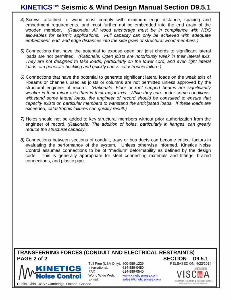
4) Screws attached to wood must comply with minimum edge distance, spacing andembedment requirements, and must further not be embedded into the end grain of thewooden member. (Rationale: All wood anchorage must be in compliance with NDSallowables for seismic applications. Full capacity can only be achieved with adequateembedment, end, and edge distances into the side grain of structural wood members.)
5) Connections that have the potential to expose open bar joist chords to significant lateralloads are not permitted. (Rationale: Open joists are notoriously weak in their lateral axis.They are not designed to take loads, particularly on the lower cord, and even light lateralloads can generate buckling and quickly cause catastrophic failure.)
6) Connections that have the potential to generate significant lateral loads on the weak axis ofI-beams or channels used as joists or columns are not permitted unless approved by thestructural engineer of record. (Rationale: Floor or roof support beams are significantlyweaker in their minor axis than in their major axis. While they can, under some conditions,withstand some lateral loads, the engineer of record should be consulted to ensure thatcapacity exists on particular members to withstand the anticipated loads. If these loads areexceeded, catastrophic failures can quickly result.)
7) Holes should not be added to key structural members without prior authorization from theengineer of record. (Rationale: The addition of holes, particularly in flanges, can greatlyreduce the structural capacity.
8) Connections between sections of conduit, trays or bus ducts can become critical factors inevaluating the performance of the system. Unless otherwise informed, Kinetics NoiseControl assumes connections to be of “medium” deformability as defined by the designcode. This is generally appropriate for steel connecting materials and fittings, brazedconnections, and plastic pipe.
KINETICS™ Seismic & Wind Design Manual Section D9.5.5
NON-MOMENT GENERATING CONNECTIONSPAGE 1 of 1 SECTION – D9.5.5
Toll Free (USA Only): 800-959-1229 RELEASED ON: 4/23/2014International: 614-889-0480FAX 614-889-0540World Wide Web: www.kineticsnoise.comE-mail: [email protected]
Dublin, Ohio, USA Cambridge, Ontario, Canada
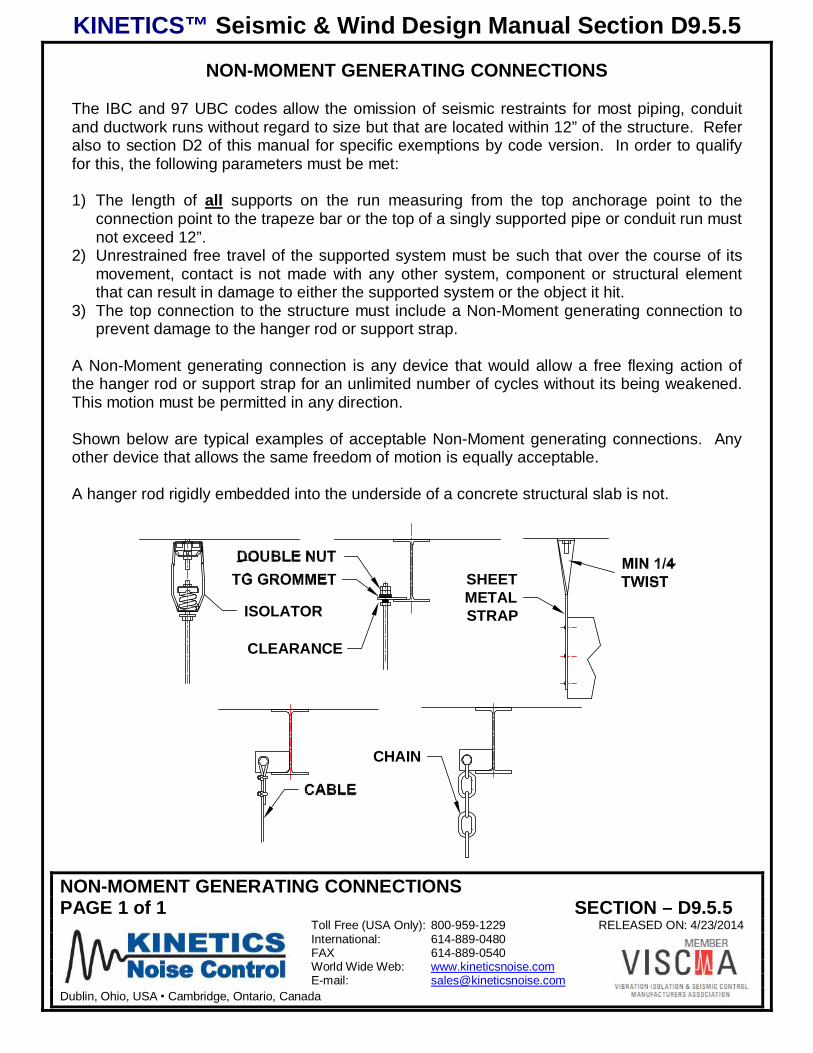
NON-MOMENT GENERATING CONNECTIONS
The IBC and 97 UBC codes allow the omission of seismic restraints for most piping, conduitand ductwork runs without regard to size but that are located within 12” of the structure. Referalso to section D2 of this manual for specific exemptions by code version. In order to qualifyfor this, the following parameters must be met:
1) The length of all supports on the run measuring from the top anchorage point to theconnection point to the trapeze bar or the top of a singly supported pipe or conduit run mustnot exceed 12”.
2) Unrestrained free travel of the supported system must be such that over the course of itsmovement, contact is not made with any other system, component or structural elementthat can result in damage to either the supported system or the object it hit.
3) The top connection to the structure must include a Non-Moment generating connection toprevent damage to the hanger rod or support strap.
A Non-Moment generating connection is any device that would allow a free flexing action ofthe hanger rod or support strap for an unlimited number of cycles without its being weakened.This motion must be permitted in any direction.
Shown below are typical examples of acceptable Non-Moment generating connections. Anyother device that allows the same freedom of motion is equally acceptable.
A hanger rod rigidly embedded into the underside of a concrete structural slab is not.
CLEARANCE
ISOLATOR
CHAIN
SHEETMETALSTRAP
KINETICS™ Seismic & Wind Design Manual Section D9.6
CONNECTION OPTIONS FOR AWKWARD SITUATIONSPAGE 1 of 5 SECTION – D9.6
Toll Free (USA Only): 800-959-1229 RELEASED ON: 4/23/2014International: 614-889-0480FAX 614-889-0540World Wide Web: www.kineticsnoise.comE-mail: [email protected]
Dublin, Ohio, USA Cambridge, Ontario, Canada
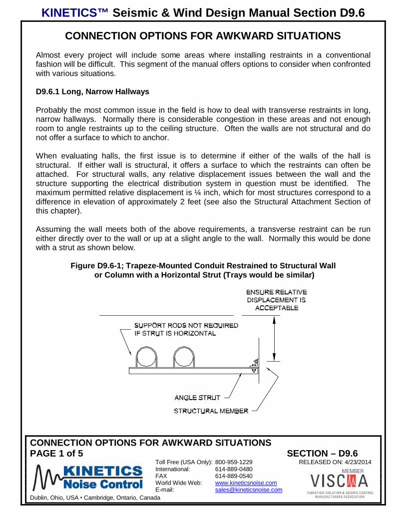
CONNECTION OPTIONS FOR AWKWARD SITUATIONSAlmost every project will include some areas where installing restraints in a conventionalfashion will be difficult. This segment of the manual offers options to consider when confrontedwith various situations.
D9.6.1 Long, Narrow Hallways
Probably the most common issue in the field is how to deal with transverse restraints in long,narrow hallways. Normally there is considerable congestion in these areas and not enoughroom to angle restraints up to the ceiling structure. Often the walls are not structural and donot offer a surface to which to anchor.
When evaluating halls, the first issue is to determine if either of the walls of the hall isstructural. If either wall is structural, it offers a surface to which the restraints can often beattached. For structural walls, any relative displacement issues between the wall and thestructure supporting the electrical distribution system in question must be identified. Themaximum permitted relative displacement is ¼ inch, which for most structures correspond to adifference in elevation of approximately 2 feet (see also the Structural Attachment Section ofthis chapter).
Assuming the wall meets both of the above requirements, a transverse restraint can be runeither directly over to the wall or up at a slight angle to the wall. Normally this would be donewith a strut as shown below.
Figure D9.6-1; Trapeze-Mounted Conduit Restrained to Structural Wall or Column with a Horizontal Strut (Trays would be similar)
KINETICS™ Seismic & Wind Design Manual Section D9.6
CONNECTION OPTIONS FOR AWKWARD SITUATIONSPAGE 2 of 5 SECTION – D9.6
Toll Free (USA Only): 800-959-1229 RELEASED ON: 4/23/2014International: 614-889-0480FAX 614-889-0540World Wide Web: www.kineticsnoise.comE-mail: [email protected]
Dublin, Ohio, USA Cambridge, Ontario, Canada
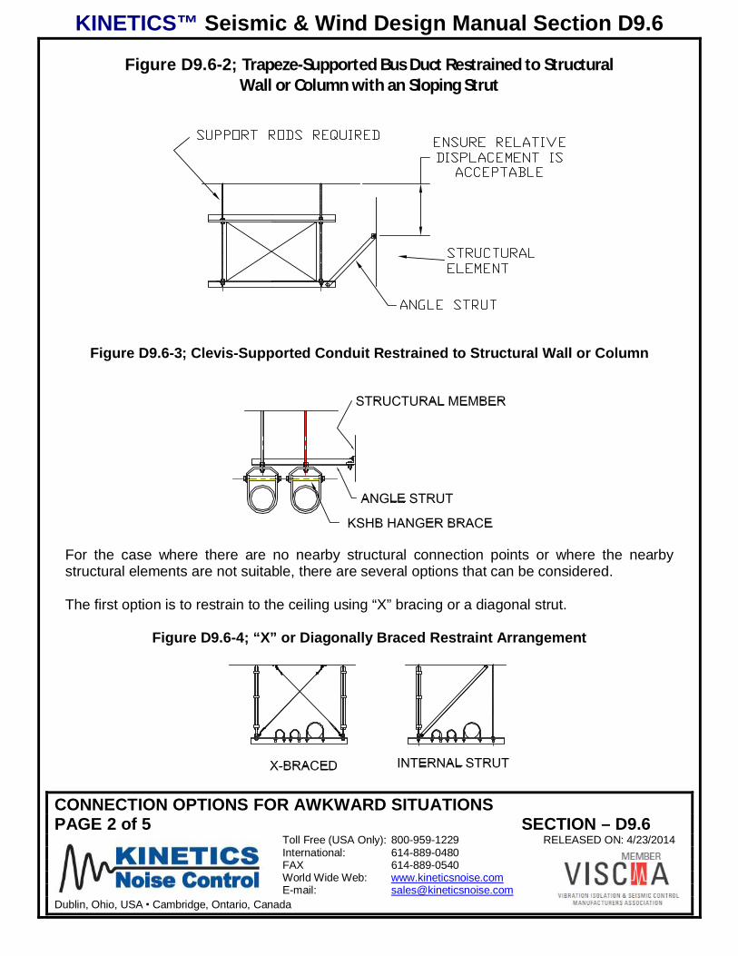
Figure D9.6-2; Trapeze-Supported Bus Duct Restrained to StructuralWall or Column with an Sloping Strut
Figure D9.6-3; Clevis-Supported Conduit Restrained to Structural Wall or Column
For the case where there are no nearby structural connection points or where the nearbystructural elements are not suitable, there are several options that can be considered.
The first option is to restrain to the ceiling using “X” bracing or a diagonal strut.
Figure D9.6-4; “X” or Diagonally Braced Restraint Arrangement
KINETICS™ Seismic & Wind Design Manual Section D9.6
CONNECTION OPTIONS FOR AWKWARD SITUATIONSPAGE 3 of 5 SECTION – D9.6
Toll Free (USA Only): 800-959-1229 RELEASED ON: 4/23/2014International: 614-889-0480FAX 614-889-0540World Wide Web: www.kineticsnoise.comE-mail: [email protected]
Dublin, Ohio, USA Cambridge, Ontario, Canada
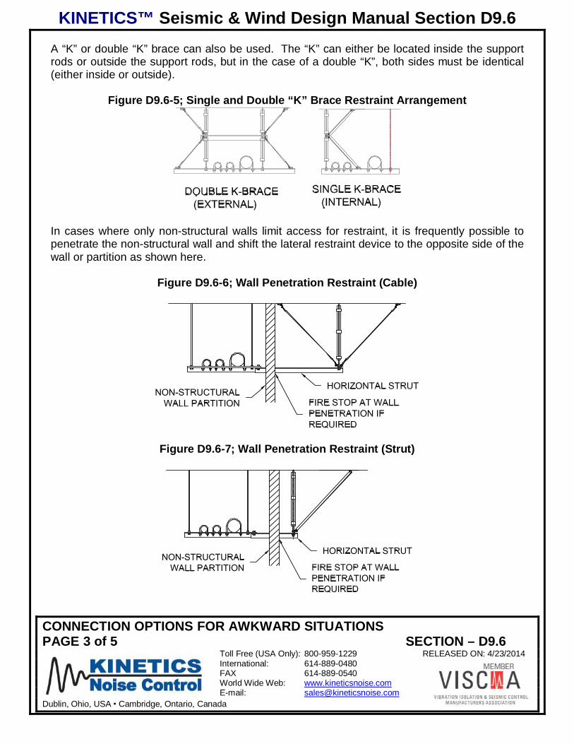
A “K” or double “K” brace can also be used. The “K” can either be located inside the supportrods or outside the support rods, but in the case of a double “K”, both sides must be identical(either inside or outside).
Figure D9.6-5; Single and Double “K” Brace Restraint Arrangement
In cases where only non-structural walls limit access for restraint, it is frequently possible topenetrate the non-structural wall and shift the lateral restraint device to the opposite side of thewall or partition as shown here.
Figure D9.6-6; Wall Penetration Restraint (Cable)
Figure D9.6-7; Wall Penetration Restraint (Strut)
KINETICS™ Seismic & Wind Design Manual Section D9.6
CONNECTION OPTIONS FOR AWKWARD SITUATIONSPAGE 4 of 5 SECTION – D9.6
Toll Free (USA Only): 800-959-1229 RELEASED ON: 4/23/2014International: 614-889-0480FAX 614-889-0540World Wide Web: www.kineticsnoise.comE-mail: [email protected]
Dublin, Ohio, USA Cambridge, Ontario, Canada
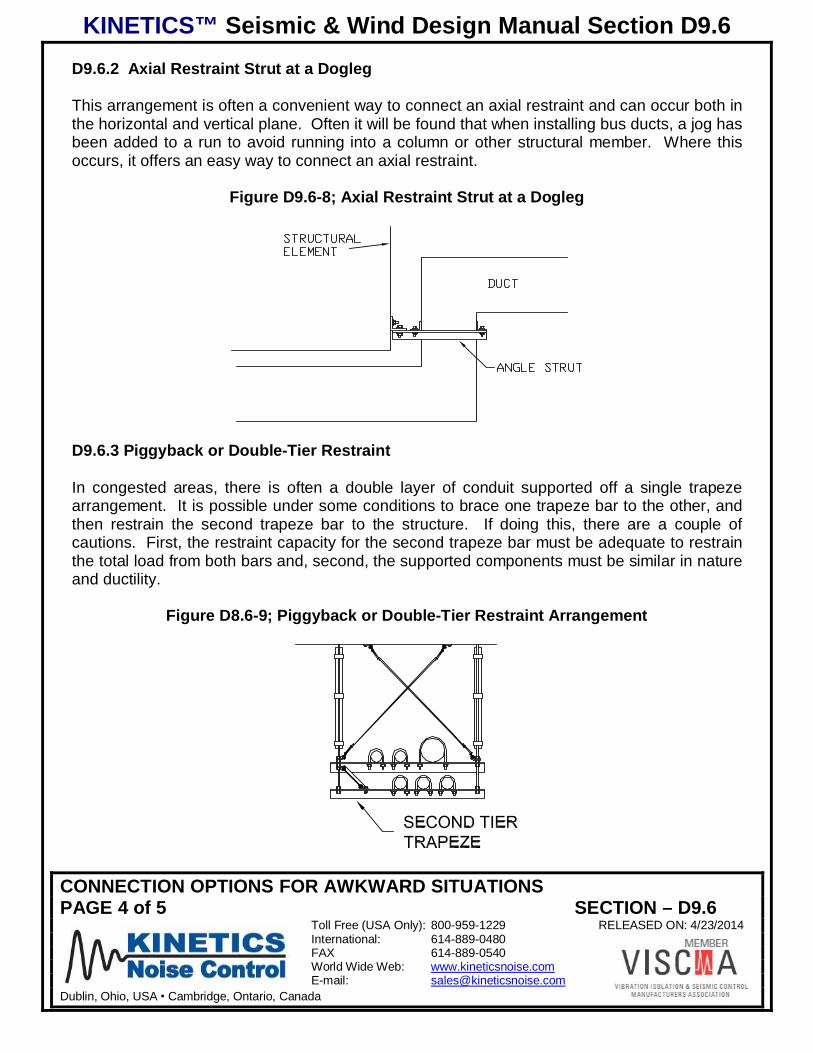
D9.6.2 Axial Restraint Strut at a Dogleg
This arrangement is often a convenient way to connect an axial restraint and can occur both inthe horizontal and vertical plane. Often it will be found that when installing bus ducts, a jog hasbeen added to a run to avoid running into a column or other structural member. Where thisoccurs, it offers an easy way to connect an axial restraint.
Figure D9.6-8; Axial Restraint Strut at a Dogleg
D9.6.3 Piggyback or Double-Tier Restraint
In congested areas, there is often a double layer of conduit supported off a single trapezearrangement. It is possible under some conditions to brace one trapeze bar to the other, andthen restrain the second trapeze bar to the structure. If doing this, there are a couple ofcautions. First, the restraint capacity for the second trapeze bar must be adequate to restrainthe total load from both bars and, second, the supported components must be similar in natureand ductility.
Figure D8.6-9; Piggyback or Double-Tier Restraint Arrangement
KINETICS™ Seismic & Wind Design Manual Section D9.6
CONNECTION OPTIONS FOR AWKWARD SITUATIONSPAGE 5 of 5 SECTION – D9.6
Toll Free (USA Only): 800-959-1229 RELEASED ON: 4/23/2014International: 614-889-0480FAX 614-889-0540World Wide Web: www.kineticsnoise.comE-mail: [email protected]
Dublin, Ohio, USA Cambridge, Ontario, Canada
D9.6.4 Restraints for conduits, ducts or trays mounted well below the support structure
This situation is not easily handled. Past history has shown, and the code is quite clear, that itis not a good idea to support a system from one structural element and restrain it usinganother structural element that will undergo significantly different motions. Restraints fit in thisfashion will likely fail or cause the supports for the system that is being supported to fail.Neither of these outcomes is desirable.
About the only solution to this is to add a support structure for the system that is located eitherjust above or just below its installed elevation. The system can then be both attached andrestrained to this structure.
The structure can be supported off the floor, off the ceiling, or from structural walls or columns.The support structure must be rigid enough to absorb all of the seismic loads, and particularlythe moments, with minimal deformation, transferring pure shear or tensile forces into thesupports.