Embed Size (px)
Citation preview

Kinetis Bootloader v1.2.0 ReferenceManual
Rev. 0, 07/2015
Contents
Section number Title Page
Chapter 1Introduction
1.1 Introduction.....................................................................................................................................................................9
1.2 Terminology....................................................................................................................................................................9
1.3 Block diagram.................................................................................................................................................................10
1.4 Features supported.......................................................................................................................................................... 10
1.5 Components supported....................................................................................................................................................11
Chapter 2Functional description
2.1 Introduction.....................................................................................................................................................................13
2.2 Memory map...................................................................................................................................................................13
2.3 The Kinetis Bootloader Configuration Area (BCA).......................................................................................................13
2.4 Start-up process...............................................................................................................................................................15
2.5 Clock configuration........................................................................................................................................................ 17
2.6 Bootloader entry point.................................................................................................................................................... 18
2.7 CRC-32 Check on application data.................................................................................................................................19
Chapter 3Kinetis bootloader protocol
3.1 Introduction.....................................................................................................................................................................21
3.2 Command with no data phase.........................................................................................................................................21
3.3 Command with incoming data phase..............................................................................................................................22
3.4 Command with outgoing data phase...............................................................................................................................23
Chapter 4Bootloader packet types
4.1 Introduction.....................................................................................................................................................................27
4.2 Ping packet......................................................................................................................................................................27
4.3 Ping response packet.......................................................................................................................................................28
4.4 Framing packet................................................................................................................................................................29
Kinetis Bootloader v1.2.0 Reference Manual, Rev. 0, 07/2015
Freescale Semiconductor, Inc. 3
Section number Title Page
4.5 CRC16 algorithm............................................................................................................................................................30
4.6 Command packet............................................................................................................................................................ 31
4.7 Response packet..............................................................................................................................................................33
Chapter 5Kinetis bootloader command API
5.1 Introduction.....................................................................................................................................................................37
5.2 GetProperty command.................................................................................................................................................... 37
5.3 SetProperty command.....................................................................................................................................................39
5.4 FlashEraseAll command................................................................................................................................................. 41
5.5 FlashEraseRegion command...........................................................................................................................................42
5.6 FlashEraseAllUnsecure command.................................................................................................................................. 43
5.7 ReadMemory command..................................................................................................................................................44
5.8 WriteMemory command.................................................................................................................................................46
5.9 FillMemory command.................................................................................................................................................... 48
5.10 FlashSecurityDisable command......................................................................................................................................50
5.11 Execute command...........................................................................................................................................................51
5.12 Call command................................................................................................................................................................. 52
5.13 Reset command...............................................................................................................................................................52
5.14 FlashProgramOnce command.........................................................................................................................................53
5.15 FlashReadOnce command.............................................................................................................................................. 55
5.16 FlashReadResource command........................................................................................................................................ 56
Chapter 6Supported peripherals
6.1 Introduction.....................................................................................................................................................................59
6.2 I2C Peripheral................................................................................................................................................................. 59
6.3 SPI Peripheral................................................................................................................................................................. 61
6.4 UART Peripheral............................................................................................................................................................ 63
6.5 USB HID Peripheral....................................................................................................................................................... 65
6.5.1 Device descriptor............................................................................................................................................... 66
Kinetis Bootloader v1.2.0 Reference Manual, Rev. 0, 07/2015
4 Freescale Semiconductor, Inc.

Section number Title Page
6.5.2 Endpoints........................................................................................................................................................... 68
6.5.3 HID reports........................................................................................................................................................ 68
6.6 FlexCAN Peripheral........................................................................................................................................................69
Chapter 7Peripheral interfaces
7.1 Introduction.....................................................................................................................................................................73
7.2 Abstract control interface................................................................................................................................................74
7.3 Abstract byte interface.................................................................................................................................................... 75
7.4 Abstract packet interface.................................................................................................................................................76
7.5 Framing packetizer..........................................................................................................................................................76
7.6 USB HID packetizer....................................................................................................................................................... 76
7.7 Command/data processor................................................................................................................................................77
Chapter 8Memory interface
8.1 Abstract interface............................................................................................................................................................ 79
8.2 Flash driver interface...................................................................................................................................................... 80
8.3 Low level flash driver..................................................................................................................................................... 81
Chapter 9Kinetis Flash Driver API
9.1 Introduction.....................................................................................................................................................................83
9.2 Flash driver data structures............................................................................................................................................. 83
9.2.1 flash_driver_t..................................................................................................................................................... 83
9.3 Flash driver API..............................................................................................................................................................84
9.3.1 flash_init.............................................................................................................................................................84
9.3.2 flash_erase_all....................................................................................................................................................85
9.3.3 flash_erase_all_unsecure................................................................................................................................... 85
9.3.4 flash_erase..........................................................................................................................................................86
9.3.5 flash_program.................................................................................................................................................... 87
9.3.6 flash_get_security_state..................................................................................................................................... 88
9.3.7 flash_security_bypass........................................................................................................................................ 89
Kinetis Bootloader v1.2.0 Reference Manual, Rev. 0, 07/2015
Freescale Semiconductor, Inc. 5

Section number Title Page
9.3.8 flash_verify_erase_all........................................................................................................................................ 90
9.3.9 flash_verify_erase.............................................................................................................................................. 91
9.3.10 flash_verify_program.........................................................................................................................................92
9.3.11 flash_get_property............................................................................................................................................. 93
9.3.12 flash_program_once...........................................................................................................................................95
9.3.13 flash_read_once................................................................................................................................................. 96
9.3.14 flash_read_resource........................................................................................................................................... 97
9.3.15 flash_register_callback.......................................................................................................................................98
9.4 Integrate Wrapped Flash Driver API to actual projects..................................................................................................99
9.4.1 Add flash.h and flash_api_tree.c to corresponding project................................................................................99
9.4.2 Include flash.h to corresponding files before calling WFDI..............................................................................101
Chapter 10Kinetis bootloader porting
10.1 Introduction.....................................................................................................................................................................103
10.2 Choosing a starting point................................................................................................................................................ 103
10.3 Preliminary porting tasks................................................................................................................................................ 103
10.3.1 Download device header files............................................................................................................................ 104
10.3.2 Copy the closest match...................................................................................................................................... 104
10.3.3 Provide device startup file (vector table)........................................................................................................... 104
10.3.4 Clean up the IAR project................................................................................................................................... 105
10.3.5 Bootloader peripherals....................................................................................................................................... 106
10.4 Primary porting tasks...................................................................................................................................................... 108
10.4.1 Header file modification.................................................................................................................................... 108
10.4.2 Bootloader peripherals....................................................................................................................................... 109
10.4.2.1 Supported peripherals........................................................................................................................ 109
10.4.2.2 Peripheral initialization...................................................................................................................... 109
10.4.2.3 Clock initialization.............................................................................................................................110
10.4.3 Bootloader configuration................................................................................................................................... 110
10.4.4 Bootloader memory map configuration............................................................................................................. 111
Kinetis Bootloader v1.2.0 Reference Manual, Rev. 0, 07/2015
6 Freescale Semiconductor, Inc.

Section number Title Page
Chapter 11Creating a custom flash-resident bootloader
11.1 Introduction.....................................................................................................................................................................113
11.2 Where to start..................................................................................................................................................................113
11.3 Flash-resident bootloader source tree............................................................................................................................. 114
11.4 Modifying source files.................................................................................................................................................... 116
11.5 Example.......................................................................................................................................................................... 116
11.6 Modifying a peripheral configuration macro..................................................................................................................117
Chapter 12Appendix A: status and error codes
Chapter 13Appendix B: GetProperty and SetProperty commands
Chapter 14Revision history
14.1 Revision History............................................................................................................................................................. 125
Kinetis Bootloader v1.2.0 Reference Manual, Rev. 0, 07/2015
Freescale Semiconductor, Inc. 7

Chapter 1Introduction
1.1 Introduction
The Kinetis bootloader is a configurable flash programming utility that operates over aserial connection on Kinetis MCUs. It enables quick and easy programming of KinetisMCUs through the entire product life cycle, including application development, finalproduct manufacturing, and beyond. The bootloader is delivered in two ways. TheKinetis bootloader is provided as full source code that is highly configurable. Thebootloader is also preprogrammed by Freescale into ROM or flash on select Kinetisdevices. Host-side command line and GUI tools are available to communicate with thebootloader. Users can utilize host tools to upload/download application code via thebootloader.
1.2 Terminology
target
The device running the bootloader firmware (aka the ROM).
host
The device sending commands to the target for execution.
source
The initiator of a communications sequence. For example, the sender of a command ordata packet.
destination
Receiver of a command or data packet.
incoming
Kinetis Bootloader v1.2.0 Reference Manual, Rev. 0, 07/2015
Freescale Semiconductor, Inc. 9

From host to target.
outgoing
From target to host.
1.3 Block diagram
This block diagram describes the overall structure of the Kinetis bootloader.
Figure 1-1. Block diagram
1.4 Features supported
Here are some of the features supported by the Kinetis bootloader:
• Supports UART, I2C, SPI, CAN, and USB peripheral interfaces.• Automatic detection of the active peripheral.• Ability to disable any peripheral.• UART peripheral implements autobaud.• Common packet-based protocol for all peripherals.• Packet error detection and retransmit.
Block diagram
Kinetis Bootloader v1.2.0 Reference Manual, Rev. 0, 07/2015
10 Freescale Semiconductor, Inc.

• Flash-resident configuration options.• Fully supports flash security, including ability to mass erase or unlock security via
the backdoor key.• Protection of RAM used by the bootloader while it is running.• Provides command to read properties of the device, such as Flash and RAM size.• Multiple options for executing the bootloader either at system start-up or under
application control at runtime.
1.5 Components supported
Components for the bootloader firmware:
• Startup code (clocking, pinmux, etc.)• Command phase state machine• Command handlers
• GenericResponse• FlashEraseAll• FlashEraseRegion• ReadMemory• ReadMemoryResponse• WriteMemory• FillMemory• FlashSecurityDisable• GetProperty• GetPropertyResponse• Execute• Call• Reset• SetProperty• FlashEraseAllUnsecure• FlashProgramOnce• FlashReadOnce• FlashReadOnceResponse• FlashReadResource• FlashReadResourceResponse
• SB file state machine• Packet interface
• Framing packetizer• Command/data packet processor
Chapter 1 Introduction
Kinetis Bootloader v1.2.0 Reference Manual, Rev. 0, 07/2015
Freescale Semiconductor, Inc. 11

• Command implementation• Flash erase all• Flash erase region• Read memory• Write memory• Fill memory• Flash security disable• Get property• Recieve SB file• Execute• Call• Reset• Set property• Flash program once• Flash read once• Flash read resource
• Memory interface• Abstract interface• Flash Driver Interface• Low level flash driver
• Peripheral drivers• I2C slave• SPI slave• CAN• UART
• Auto-baud detector• USB device HID class
• USB controller driver• USB framework• USB HID class
• CRC check engine• CRC algorithm
Components supported
Kinetis Bootloader v1.2.0 Reference Manual, Rev. 0, 07/2015
12 Freescale Semiconductor, Inc.
Chapter 2Functional description
2.1 IntroductionThe following subsections describe the Kinetis bootloader functionality.
2.2 Memory map
See the Kinetis bootloader chapter of the reference manual of the particular SoC for theROM and RAM memory map used by the bootloader.
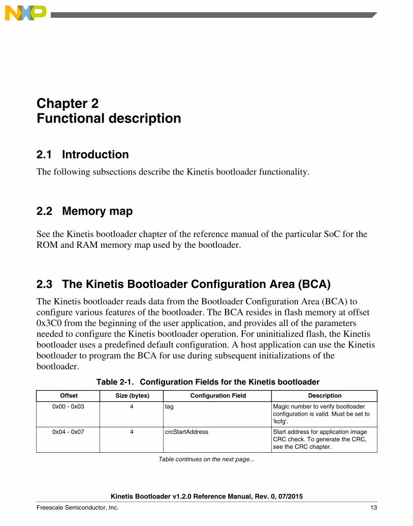
2.3 The Kinetis Bootloader Configuration Area (BCA)The Kinetis bootloader reads data from the Bootloader Configuration Area (BCA) toconfigure various features of the bootloader. The BCA resides in flash memory at offset0x3C0 from the beginning of the user application, and provides all of the parametersneeded to configure the Kinetis bootloader operation. For uninitialized flash, the Kinetisbootloader uses a predefined default configuration. A host application can use the Kinetisbootloader to program the BCA for use during subsequent initializations of thebootloader.
Table 2-1. Configuration Fields for the Kinetis bootloader
Offset Size (bytes) Configuration Field Description
0x00 - 0x03 4 tag Magic number to verify bootloaderconfiguration is valid. Must be set to'kcfg'.
0x04 - 0x07 4 crcStartAddress Start address for application imageCRC check. To generate the CRC,see the CRC chapter.
Table continues on the next page...
Kinetis Bootloader v1.2.0 Reference Manual, Rev. 0, 07/2015
Freescale Semiconductor, Inc. 13

Table 2-1. Configuration Fields for the Kinetis bootloader (continued)
Offset Size (bytes) Configuration Field Description
0x08 - 0x0B 4 crcByteCount Byte count for application image CRCcheck.
0x0C - 0x0F 4 crcExpectedValue Expected CRC value for applicationCRC check.
0x10 1 enabledPeripherals Bitfield of peripherals to enable.
bit 0 LPUART
bit 1 I2C
bit 2 SPI
bit 4 USB
0x11 1 i2cSlaveAddress If not 0xFF, used as the 7-bit I2Cslave address.
0x12 - 0x13 2 peripheralDetectionTimeout If not 0xFF, used as the timeout inmilliseconds for active peripheraldetection.
0x14 - 0x15 2 usbVid Sets the USB Vendor ID reported bythe device during enumeration.
0x16- 0x17 2 usbPid Sets the USB Product ID reported bythe device during enumeration.
0x18 - 0x1B 4 usbStringsPointer Sets the USB Strings reported by thedevice during enumeration.
0x1C 1 clockFlags See clockFlags Configuration Field.
0x1D 1 clockDivider Inverted value of the divider used forcore and bus clocks when in high-speed mode.
0x1E 1 bootFlags One's complement of direct boot flag.0xFE represents direct boot.
0x1F 1 pad0 Reserved, set to 0xFF.
0x20 - 0x23 4 mmcauConfigPointer Reserved, holds a pointer value to theMMCAU configuration.
0x24 - 0x27 4 keyBlobPointer Reserved, holds a value to the keyblob array used to configure OTFAD.
0x28 1 pad1 Reserved.
0x29 1 canConfig1 ClkSel[1], PropSeg[3], SpeedIndex[4]
0x2A - 0x2B 2 canConfig2 Pdiv[8], Pseg[3], Pseg2[3], rjw[2]
0x2C - 0x2D 2 canTxId txId
0x2E - 0x2F 2 canRxId rxId
The Kinetis Bootloader Configuration Area (BCA)
Kinetis Bootloader v1.2.0 Reference Manual, Rev. 0, 07/2015
14 Freescale Semiconductor, Inc.

The first configuration field 'tag' is a tag value or magic number. The tag value must beset to 'kcfg' for the bootloader configuration data to be recognized as valid. If tag-fieldverification fails, the Kinetis bootloader acts as if the configuration data is not present.The tag value is treated as a character string, so bytes 0-3 must be set as shown in thetable.
Table 2-2. tag Configuration Field
Offset tag Byte Value
0 'k' (0x6B)
1 'c' (0x63)
2 'f' (0x66)
3 'g' (0x67)
The flags in the clockFlags configuration field are enabled if the corresponding bit iscleared (0).
Table 2-3. clockFlags Configuration Field
Bit Flag Description
0 HighSpeed Enable high-speed mode (i.e., 48 MHz).
1 - 7 - Reserved.
2.4 Start-up processIt is important to note that the startup process for bootloader in ROM, RAM (flashloader),and flash (flash-resident) are slightly different. See the chip-specific reference manual forunderstanding the startup process for the ROM bootloader and flashloader. This sectionfocuses on the flash-resident bootloader startup only.
There are two ways to get into the flash-resident bootloader.
1. If the PC holds the start address of the flash-resident bootloader and the valid SP, thehardware boots into the bootloader.
2. A user application running on flash or RAM calls into the Kinetis bootloader entrypoint address in flash to start the Kinetis bootloader execution.
After the Kinetis bootloader has started, the following procedure starts the bootloaderoperations:
1. Initializes the bootloader's .data and .bss sections.2. Reads the bootloader configuration data from flash at offset 0x3C0. The
configuration data is only used if the tag field is set to the expected 'kcfg' value. If the
Chapter 2 Functional description
Kinetis Bootloader v1.2.0 Reference Manual, Rev. 0, 07/2015
Freescale Semiconductor, Inc. 15

tag is incorrect, the configuration values are set to default, as if the data was all 0xFFbytes.
3. Clocks are configured.4. Enabled peripherals are initialized.5. The the bootloader waits for communication to begin on a peripheral.
• If detection times out, the bootloader jumps to the user application in flash if thevalid PC and SP addresses are specified in the application vector table.
• If communication is detected, all inactive peripherals are shut down, and thecommand phase is entered.
Start-up process
Kinetis Bootloader v1.2.0 Reference Manual, Rev. 0, 07/2015
16 Freescale Semiconductor, Inc.
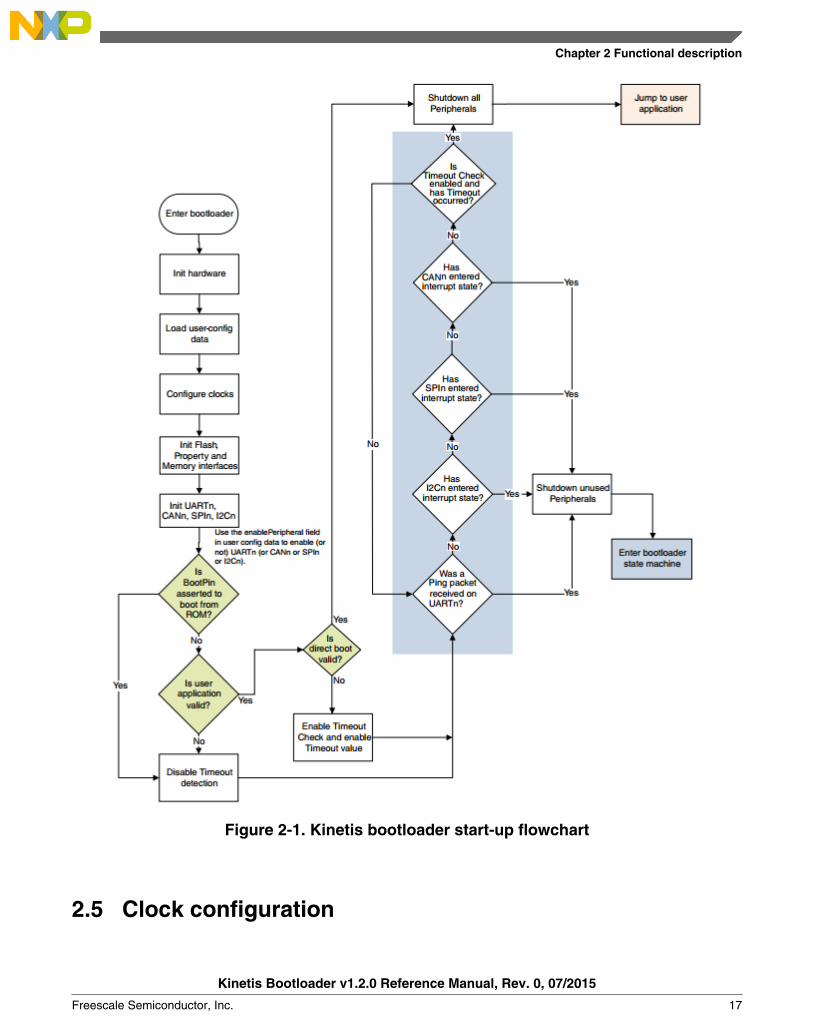
Figure 2-1. Kinetis bootloader start-up flowchart
2.5 Clock configuration
Chapter 2 Functional description
Kinetis Bootloader v1.2.0 Reference Manual, Rev. 0, 07/2015
Freescale Semiconductor, Inc. 17

The clock configuration used by the bootloader depends on the clock settings in thebootloader configuration area and the requirements of the enabled peripherals. Thebootloader starts by using the default clock configuration of the part out of reset.
• Alternate clock configurations are supported by setting fields in the bootloaderconfiguration data.
• If the HighSpeed flag of the clockFlags configuration value is cleared, the core andbus clock frequencies are determined by the clockDivider configuration value.
• The core clock divider is set directly from the inverted value of clockDivider, unlessa USB peripheral is enabled. If a USB peripheral is enabled and clockDivider isgreater than 2, clockDivider is reduced to 2 in order to keep the CPU clock above 20MHz.
• The bus clock divider is set to 1, unless the resulting bus clock frequency would begreater than the maximum supported value. In this instance, the bus clock divider isincreased until the bus clock frequency is at or below the maximum.
• The flash clock divider is set to 1, unless the resulting flash clock frequency wouldbe greater than the maximum supported value. In this instance, the flash clockdivider is increased until the flash clock frequency is at or below the maximum.
• If flex bus is available, the flex bus clock divider is set to 1, unless the resulting flexbus clock frequency would be greater than the maximum supported value. In thisinstance, the flex bus clock divider is increased until the flex bus clock frequency isat or below the maximum.
• If a USB peripheral is enabled, the IRC48Mhz clock is selected as the USBperipheral clock and the clock recovery feature is enabled.
• Note that the maximum baud rate of serial peripherals is related to the core and busclock frequencies.
2.6 Bootloader entry pointThe Kinetis bootloader provides a function (runBootloader) that a user application cancall, to run the bootloader.
NOTEFlashloader does not support this feature.
To get the address of the entry point, the user application reads the word containing thepointer to the bootloader API tree at offset 0x1C of the bootloader's vector table. Thevector table is placed at the base of the bootloader's address range.
The bootloader API tree is a structure that contains pointers to other structures, whichhave the function and data addresses for the bootloader. The bootloader entry point isalways the first word of the API tree.
Bootloader entry point
Kinetis Bootloader v1.2.0 Reference Manual, Rev. 0, 07/2015
18 Freescale Semiconductor, Inc.
The prototype of the entry point is:
void run_bootloader(void * arg);
The arg parameter is currently unused, and intended for future expansion. For example,passing options to the bootloader. To ensure future compatibility, a value of NULLshould be passed for arg.
Example code to get the entry pointer address from the ROM and start the bootloader:
// Variables
uint32_t runBootloaderAddress;
void (*runBootloader)(void * arg);
// Read the function address from the ROM API tree.
runBootloaderAddress = **(uint32_t **)(0x1c00001c);
runBootloader = (void (*)(void * arg))runBootloaderAddress;
// Start the bootloader.
runBootloader(NULL);
NOTEThe user application must be executing at Supervisor(Privileged) level when calling the bootloader entry point.
2.7 CRC-32 Check on application data
Using CRC-32 and a given address range, the ROM bootloader supports performing anapplication integrity check. To properly configure this functionality, the following fieldsin the bootloader configuration area must be set:
• Set crcStartAddress to the start address that should be used for the CRC check.• Set crcByteCount to the number of bytes to run the CRC check on, from the start
address.• Set crcExpectedValue to the value that the CRC calculation should result in.
Considerations:
Chapter 2 Functional description
Kinetis Bootloader v1.2.0 Reference Manual, Rev. 0, 07/2015
Freescale Semiconductor, Inc. 19

• If all of the above fields are unset (all 0xFF bytes for crcStartAddress, crcByteCount,and crcExpectedValue), then the ROM bootloader returnskStatus_AppCrcCheckInvalid.
• If any one of the above fields are set (crcStartAddress, crcByteCount, andcrcExpectedValue), then the ROM bootloader checks if the given address range ofthe application is valid and if the application just resides in internal flash or externalQSPI flash:
• If false, then the bootloader returns kStatus_AppCrcCheckOutOfRange.• If true, then the CRC check occurs. If the CRC check fails, then the bootloader
returns kStatus_AppCrcCheckFailed; if the CRC check succeeds, then it returnskStatus_AppCrcCheckPassed.
• If the bootloader returns kStatus_AppCrcCheckOutOfRange orkStatus_AppCrcCheckFailed, then an external pin (PTA6) will also be asserted,to indicate CRC check failure.
NOTEPTA6 is only available on the 121 MAP BGA and 100 LQFPpackages.
• Only if kStatus_AppCrcCheckPassed is returned, will the application be jumped to;otherwise the bootloader will stay active, and wait for further commands.
CRC-32 Check on application data
Kinetis Bootloader v1.2.0 Reference Manual, Rev. 0, 07/2015
20 Freescale Semiconductor, Inc.

Chapter 3Kinetis bootloader protocol
3.1 Introduction
This section explains the general protocol for the packet transfers between the host andthe Kinetis bootloader. The description includes the transfer of packets for differenttransactions, such as commands with no data phase and commands with incoming oroutgoing data phase. The next section describes various packet types used in atransaction.
Each command sent from the host is replied to with a response command.
Commands may include an optional data phase.
• If the data phase is incoming (from the host to Kinetis bootloader ), it is part of theoriginal command.
• If the data phase is outgoing (from Kinetis bootloader to host), it is part of theresponse command.
3.2 Command with no data phase
NOTEIn these diagrams, the Ack sent in response to a Command orData packet can arrive at any time before, during, or after theCommand/Data packet has processed.
Command with no data phase
The protocol for a command with no data phase contains:
• Command packet (from host)• Generic response command packet (to host)
Kinetis Bootloader v1.2.0 Reference Manual, Rev. 0, 07/2015
Freescale Semiconductor, Inc. 21
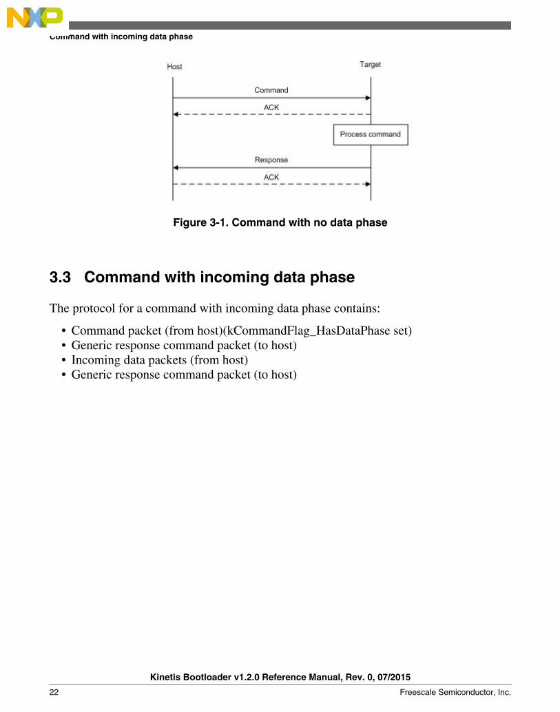
Figure 3-1. Command with no data phase
3.3 Command with incoming data phase
The protocol for a command with incoming data phase contains:
• Command packet (from host)(kCommandFlag_HasDataPhase set)• Generic response command packet (to host)• Incoming data packets (from host)• Generic response command packet (to host)
Command with incoming data phase
Kinetis Bootloader v1.2.0 Reference Manual, Rev. 0, 07/2015
22 Freescale Semiconductor, Inc.

Figure 3-2. Command with incoming data phase
Notes
• The host may not send any further packets while it is waiting for the response to acommand.
• The data phase is aborted if the Generic Response packet prior to the start of the dataphase does not have a status of kStatus_Success.
• Data phases may be aborted by the receiving side by sending the final GenericResponse early with a status of kStatus_AbortDataPhase. The host may abort thedata phase early by sending a zero-length data packet.
• The final Generic Response packet sent after the data phase includes the status forthe entire operation.
3.4 Command with outgoing data phase
Chapter 3 Kinetis bootloader protocol
Kinetis Bootloader v1.2.0 Reference Manual, Rev. 0, 07/2015
Freescale Semiconductor, Inc. 23

The protocol for a command with an outgoing data phase contains:
• Command packet (from host)• ReadMemory Response command packet (to host)(kCommandFlag_HasDataPhase
set)• Outgoing data packets (to host)• Generic response command packet (to host)
Figure 3-3. Command with outgoing data phase
Note
• The data phase is considered part of the response command for the outgoing dataphase sequence.
• The host may not send any further packets while the host is waiting for the responseto a command.
• The data phase is aborted if the ReadMemory Response command packet, prior tothe start of the data phase, does not contain the kCommandFlag_HasDataPhase flag.
Command with outgoing data phase
Kinetis Bootloader v1.2.0 Reference Manual, Rev. 0, 07/2015
24 Freescale Semiconductor, Inc.

• Data phases may be aborted by the host sending the final Generic Response earlywith a status of kStatus_AbortDataPhase. The sending side may abort the data phaseearly by sending a zero-length data packet.
• The final Generic Response packet sent after the data phase includes the status forthe entire operation.
Chapter 3 Kinetis bootloader protocol
Kinetis Bootloader v1.2.0 Reference Manual, Rev. 0, 07/2015
Freescale Semiconductor, Inc. 25

Chapter 4Bootloader packet types
4.1 IntroductionThe Kinetis bootloader device works in slave mode. All data communication is initiatedby a host, which is either a PC or an embedded host. The Kinetis bootloader device is thetarget, which receives a command or data packet. All data communication between hostand target is packetized.
NOTEThe term "target" refers to the "Kinetis bootloader device".
There are 6 types of packets used:• Ping packet• Ping Response packet• Framing packet• Command packet• Data packet• Response packet
All fields in the packets are in little-endian byte order.
4.2 Ping packetThe Ping packet is the first packet sent from a host to the target to establish a connectionon selected peripheral in order to run autobaud. The Ping packet can be sent from host totarget at any time that the target is expecting a command packet. If the selected peripheralis UART, a ping packet must be sent before any other communications. For other serialperipherals it is optional, but is recommended in order to determine the serial protocolversion.
In response to a Ping packet, the target sends a Ping Response packet, discussed in latersections.
Kinetis Bootloader v1.2.0 Reference Manual, Rev. 0, 07/2015
Freescale Semiconductor, Inc. 27

Table 4-1. Ping Packet Format
Byte # Value Name
0 0x5A start byte
1 0xA6 ping
Target executes UART autobaud if necessary
Host Target
PingResponse Packet: 0x5a 0xa7 0x00 0x02 0x01 0x50 0x00 0x00 0xaa 0xea
Ping Packet 0x5a 0xa6
Figure 4-1. Ping Packet Protocol Sequence
4.3 Ping response packetThe target sends a Ping Response packet back to the host after receiving a Ping packet. Ifcommunication is over a UART peripheral, the target uses the incoming Ping packet todetermine the baud rate before replying with the Ping Response packet. Once the PingResponse packet is received by the host, the connection is established, and the host startssending commands to the target.
Table 4-2. Ping Response packet format
Byte # Value Parameter
0 0x5A start byte
1 0xA7 Ping response code
2 Protocol bugfix
3 Protocol minor
4 Protocol major
5 Protocol name = 'P' (0x50)
6 Options low
7 Options high
Table continues on the next page...
Ping response packet
Kinetis Bootloader v1.2.0 Reference Manual, Rev. 0, 07/2015
28 Freescale Semiconductor, Inc.
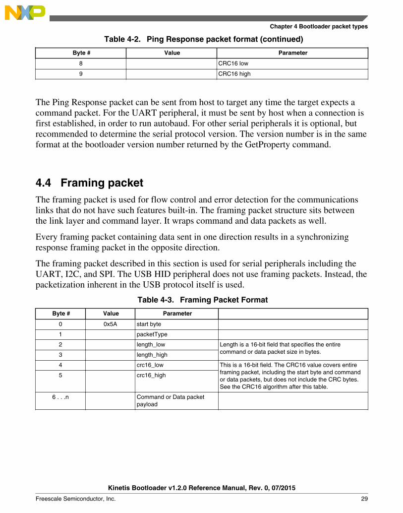
Table 4-2. Ping Response packet format (continued)
Byte # Value Parameter
8 CRC16 low
9 CRC16 high
The Ping Response packet can be sent from host to target any time the target expects acommand packet. For the UART peripheral, it must be sent by host when a connection isfirst established, in order to run autobaud. For other serial peripherals it is optional, butrecommended to determine the serial protocol version. The version number is in the sameformat at the bootloader version number returned by the GetProperty command.
4.4 Framing packetThe framing packet is used for flow control and error detection for the communicationslinks that do not have such features built-in. The framing packet structure sits betweenthe link layer and command layer. It wraps command and data packets as well.
Every framing packet containing data sent in one direction results in a synchronizingresponse framing packet in the opposite direction.
The framing packet described in this section is used for serial peripherals including theUART, I2C, and SPI. The USB HID peripheral does not use framing packets. Instead, thepacketization inherent in the USB protocol itself is used.
Table 4-3. Framing Packet Format
Byte # Value Parameter
0 0x5A start byte
1 packetType
2 length_low Length is a 16-bit field that specifies the entirecommand or data packet size in bytes.3 length_high
4 crc16_low This is a 16-bit field. The CRC16 value covers entireframing packet, including the start byte and commandor data packets, but does not include the CRC bytes.See the CRC16 algorithm after this table.
5 crc16_high
6 . . .n Command or Data packetpayload
Chapter 4 Bootloader packet types
Kinetis Bootloader v1.2.0 Reference Manual, Rev. 0, 07/2015
Freescale Semiconductor, Inc. 29
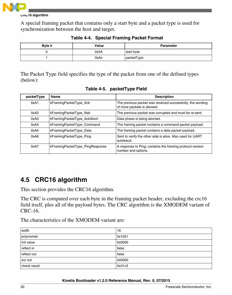
A special framing packet that contains only a start byte and a packet type is used forsynchronization between the host and target.
Table 4-4. Special Framing Packet Format
Byte # Value Parameter
0 0x5A start byte
1 0xAn packetType
The Packet Type field specifies the type of the packet from one of the defined types(below):
Table 4-5. packetType Field
packetType Name Description
0xA1 kFramingPacketType_Ack The previous packet was received successfully; the sendingof more packets is allowed.
0xA2 kFramingPacketType_Nak The previous packet was corrupted and must be re-sent.
0xA3 kFramingPacketType_AckAbort Data phase is being aborted.
0xA4 kFramingPacketType_Command The framing packet contains a command packet payload.
0xA5 kFramingPacketType_Data The framing packet contains a data packet payload.
0xA6 kFramingPacketType_Ping Sent to verify the other side is alive. Also used for UARTautobaud.
0xA7 kFramingPacketType_PingResponse A response to Ping; contains the framing protocol versionnumber and options.
4.5 CRC16 algorithmThis section provides the CRC16 algorithm.
The CRC is computed over each byte in the framing packet header, excluding the crc16field itself, plus all of the payload bytes. The CRC algorithm is the XMODEM variant ofCRC-16.
The characteristics of the XMODEM variant are:
width 16
polynomial 0x1021
init value 0x0000
reflect in false
reflect out false
xor out 0x0000
check result 0x31c3
CRC16 algorithm
Kinetis Bootloader v1.2.0 Reference Manual, Rev. 0, 07/2015
30 Freescale Semiconductor, Inc.
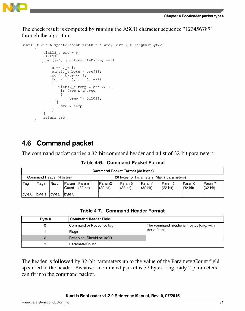
The check result is computed by running the ASCII character sequence "123456789"through the algorithm.
uint16_t crc16_update(const uint8_t * src, uint32_t lengthInBytes { uint32_t crc = 0; uint32_t j; for (j=0; j < lengthInBytes; ++j) { uint32_t i; uint32_t byte = src[j]; crc ^= byte << 8; for (i = 0; i < 8; ++i) { uint32_t temp = crc << 1; if (crc & 0x8000) { temp ^= 0x1021; } crc = temp; } } return crc; }
4.6 Command packetThe command packet carries a 32-bit command header and a list of 32-bit parameters.
Table 4-6. Command Packet Format
Command Packet Format (32 bytes)
Command Header (4 bytes) 28 bytes for Parameters (Max 7 parameters)
Tag Flags Rsvd ParamCount
Param1(32-bit)
Param2(32-bit)
Param3(32-bit)
Param4(32-bit)
Param5(32-bit)
Param6(32-bit)
Param7(32-bit)
byte 0 byte 1 byte 2 byte 3
Table 4-7. Command Header Format
Byte # Command Header Field
0 Command or Response tag The command header is 4 bytes long, withthese fields.1 Flags
2 Reserved. Should be 0x00.
3 ParameterCount
The header is followed by 32-bit parameters up to the value of the ParameterCount fieldspecified in the header. Because a command packet is 32 bytes long, only 7 parameterscan fit into the command packet.
Chapter 4 Bootloader packet types
Kinetis Bootloader v1.2.0 Reference Manual, Rev. 0, 07/2015
Freescale Semiconductor, Inc. 31

Command packets are also used by the target to send responses back to the host. Asmentioned earlier, command packets and data packets are embedded into framing packetsfor all of the transfers.
Table 4-8. Command Tags
Command Tag Name
0x01 FlashEraseAll The command tag specifies one of thecommands supported by the Kinetisbootloader. The valid command tags for theKinetis bootloader are listed here.
0x02 FlashEraseRegion
0x03 ReadMemory
0x04 WriteMemory
0x05 FillMemory
0x06 FlashSecurityDisable
0x07 GetProperty
0x08 Reserved
0x09 Execute
0x10 FlashReadResource
0x11 Reserved
0x0A Call
0x0B Reset
0x0C SetProperty
0x0D FlashEraseAllUnsecure
0x0D Reserved
0x0E FlashProgramOnce
0x0F FlashReadOnce
Table 4-9. Response Tags
Response Tag Name
0xA0 GenericResponse The response tag specifies one of the responsesthe Kinetis bootloader (target) returns to the host.The valid response tags are listed here.
0xA0 GenericResponse The response tag specifies one of the responsesthe Kinetis bootloader (target) returns to the host.The valid response tags are listed here.
0xA7 GetPropertyResponse (used for sendingresponses to GetProperty command only)
0xA3 ReadMemoryResponse (used for sendingresponses to ReadMemory command only)
0xAF FlashReadOnceResponse (used for sendingresponses to FlashReadOnce command only)
0xB0 FlashReadResourceResponse (used for sendingresponses to FlashReadResource commandonly)
Command packet
Kinetis Bootloader v1.2.0 Reference Manual, Rev. 0, 07/2015
32 Freescale Semiconductor, Inc.

Flags: Each command packet contains a Flag byte. Only bit 0 of the flag byte is used. Ifbit 0 of the flag byte is set to 1, then data packets follow in the command sequence. Thenumber of bytes that are transferred in the data phase is determined by a command-specific parameter in the parameters array.
ParameterCount: The number of parameters included in the command packet.
Parameters: The parameters are word-length (32 bits). With the default maximumpacket size of 32 bytes, a command packet can contain up to 7 parameters.
4.7 Response packetThe responses are carried using the same command packet format wrapped with framingpacket data. Types of responses include:
• GenericResponse• GetPropertyResponse• ReadMemoryResponse• FlashReadOnceResponse• FlashReadResourceResponse
GenericResponse: After the Kinetis bootloader has processed a command, thebootloader sends a generic response with status and command tag information to the host.The generic response is the last packet in the command protocol sequence. The genericresponse packet contains the framing packet data and the command packet data (withgeneric response tag = 0xA0) and a list of parameters (defined in the next section). Theparameter count field in the header is always set to 2, for status code and command tagparameters.
Table 4-10. GenericResponse Parameters
Byte # Parameter Descripton
0 - 3 Status code The Status codes are errors encountered during the execution of acommand by the target. If a command succeeds, then a kStatus_Successcode is returned.
4 - 7 Command tag The Command tag parameter identifies the response to the command sentby the host.
GetPropertyResponse: The GetPropertyResponse packet is sent by the target inresponse to the host query that uses the GetProperty command. The GetPropertyResponsepacket contains the framing packet data and the command packet data, with thecommand/response tag set to a GetPropertyResponse tag value (0xA7).
Chapter 4 Bootloader packet types
Kinetis Bootloader v1.2.0 Reference Manual, Rev. 0, 07/2015
Freescale Semiconductor, Inc. 33

The parameter count field in the header is set to greater than 1, to always include thestatus code and one or many property values.
Table 4-11. GetPropertyResponse Parameters
Byte # Value Parameter
0 - 3 Status code
4 - 7 Property value
. . . . . .
Can be up to maximum 6 property values, limited to the size of the 32-bitcommand packet and property type.
ReadMemoryResponse: The ReadMemoryResponse packet is sent by the target inresponse to the host sending a ReadMemory command. The ReadMemoryResponsepacket contains the framing packet data and the command packet data, with thecommand/response tag set to a ReadMemoryResponse tag value (0xA3), the flags fieldset to kCommandFlag_HasDataPhase (1).
The parameter count set to 2 for the status code and the data byte count parameters shownbelow.
Table 4-12. ReadMemoryResponse Parameters
Byte # Parameter Descripton
0 - 3 Status code The status of the associated Read Memory command.
4 - 7 Data byte count The number of bytes sent in the data phase.
FlashReadOnceResponse:The FlashReadOnceResponse packet is sent by the target inresponse to the host sending a FlashReadOnce command. The FlashReadOnceResponsepacket contains the framing packet data and the command packet data, with thecommand/response tag set to a FlashReadOnceResponse tag value (0xAF), and the flagsfield set to 0. The parameter count is set to 2 plus the number of words requested to beread in the FlashReadOnceCommand.
Table 4-13. FlashReadOnceResponse Parameters
Byte # Value Parameter
0 – 3 Status Code
4 – 7 Byte count to read
… …
Can be up to 20 bytes of requested read data.
Response packet
Kinetis Bootloader v1.2.0 Reference Manual, Rev. 0, 07/2015
34 Freescale Semiconductor, Inc.

The FlashReadResourceResponse packet is sent by the target in response to the hostsending a FlashReadResource command. The FlashReadResourceResponse packetcontains the framing packet data and command packet data, with the command/responsetag set to a FlashReadResourceResponse tag value (0xB0), and the flags field set tokCommandFlag_HasDataPhase (1).
Table 4-14. FlashReadResourceResponse Parameters
Byte # Value Parameter
0 – 3 Status Code
4 – 7 Data byte count
Chapter 4 Bootloader packet types
Kinetis Bootloader v1.2.0 Reference Manual, Rev. 0, 07/2015
Freescale Semiconductor, Inc. 35

Chapter 5Kinetis bootloader command API
5.1 Introduction
All Kinetis bootloader command APIs follows the command packet format wrapped bythe framing packet as explained in previous sections.
See Table 4-8 for a list of commands supported by Kinetis bootloader.
For a list of status codes returned by Kinetis bootloader see Appendix A.
5.2 GetProperty commandThe GetProperty command is used to query the bootloader about various properties andsettings. Each supported property has a unique 32-bit tag associated with it. The tagoccupies the first parameter of the command packet. The target returns aGetPropertyResponse packet with the property values for the property identified with thetag in the GetProperty command.
Properties are the defined units of data that can be accessed with the GetProperty orSetProperty commands. Properties may be read-only or read-write. All read-writeproperties are 32-bit integers, so they can easily be carried in a command parameter.
For a list of properties and their associated 32-bit property tags supported by Kinetisbootloader, see Appendix B.
The 32-bit property tag is the only parameter required for GetProperty command.
Table 5-1. Parameters for GetProperty Command
Byte # Command
0 - 3 Property tag
4 - 7 External Memory Identifier (only applies to get property for external memory)
Kinetis Bootloader v1.2.0 Reference Manual, Rev. 0, 07/2015
Freescale Semiconductor, Inc. 37

Process command
Host Target
GetProperty: Property tag = 0x010x5a a4 08 00 73 d4 07 00 00 01 01 00 00 00
0x5a a4 0c 00 07 7a a7 00 00 02 00 00 00 00 00 00 01 4b
ACK:0x5a a1
ACK:0x5a a1
Generic Response:
Figure 5-1. Protocol Sequence for GetProperty Command
Table 5-2. GetProperty Command Packet Format (Example)
GetProperty Parameter Value
Framing packet start byte 0x5A
packetType 0xA4, kFramingPacketType_Command
length 0x08 0x00
crc16 0x73 0xD4
Command packet commandTag 0x07 – GetProperty
flags 0x00
reserved 0x00
parameterCount 0x01
propertyTag 0x00000001 - CurrentVersion
The GetProperty command has no data phase.
Response: In response to a GetProperty command, the target sends aGetPropertyResponse packet with the response tag set to 0xA7. The parameter countindicates the number of parameters sent for the property values, with the first parametershowing status code 0, followed by the property value(s). The next table shows anexample of a GetPropertyResponse packet.
Table 5-3. GetProperty Response Packet Format (Example)
GetPropertyResponse Parameter Value
Framing packet start byte 0x5A
packetType 0xA4, kFramingPacketType_Command
Table continues on the next page...
GetProperty command
Kinetis Bootloader v1.2.0 Reference Manual, Rev. 0, 07/2015
38 Freescale Semiconductor, Inc.

Table 5-3. GetProperty Response Packet Format (Example) (continued)
GetPropertyResponse Parameter Value
length 0x0c 0x00 (12 bytes)
crc16 0x07 0x7a
Command packet responseTag 0xA7
flags 0x00
reserved 0x00
parameterCount 0x02
status 0x00000000
propertyValue 0x0000014b - CurrentVersion
5.3 SetProperty commandThe SetProperty command is used to change or alter the values of the properties oroptions of the bootloader. The command accepts the same property tags used with theGetProperty command. However, only some properties are writable--see Appendix B. Ifan attempt to write a read-only property is made, an error is returned indicating theproperty is read-only and cannot be changed.
The property tag and the new value to set are the two parameters required for theSetProperty command.
Table 5-4. Parameters for SetProperty Command
Byte # Command
0 - 3 Property tag
4 - 7 Property value
Chapter 5 Kinetis bootloader command API
Kinetis Bootloader v1.2.0 Reference Manual, Rev. 0, 07/2015
Freescale Semiconductor, Inc. 39
Process command
Host Target
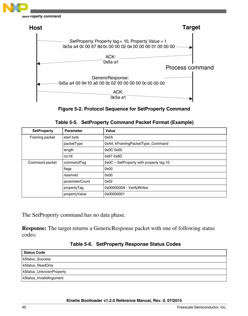
SetProperty: Property tag = 10, Property Value = 10x5a a4 0c 00 67 8d 0c 00 00 02 0a 00 00 00 01 00 00 00
GenericResponse:0x5a a4 00 9e 10 a0 00 0c 02 00 00 00 00 0c 00 00 00
ACK:0x5a a1
ACK:0x5a a1
Figure 5-2. Protocol Sequence for SetProperty Command
Table 5-5. SetProperty Command Packet Format (Example)
SetProperty Parameter Value
Framing packet start byte 0x5A
packetType 0xA4, kFramingPacketType_Command
length 0x0C 0x00
crc16 0x67 0x8D
Command packet commandTag 0x0C – SetProperty with property tag 10
flags 0x00
reserved 0x00
parameterCount 0x02
propertyTag 0x0000000A - VerifyWrites
propertyValue 0x00000001
The SetProperty command has no data phase.
Response: The target returns a GenericResponse packet with one of following statuscodes:
Table 5-6. SetProperty Response Status Codes
Status Code
kStatus_Success
kStatus_ReadOnly
kStatus_UnknownProperty
kStatus_InvalidArgument
SetProperty command
Kinetis Bootloader v1.2.0 Reference Manual, Rev. 0, 07/2015
40 Freescale Semiconductor, Inc.
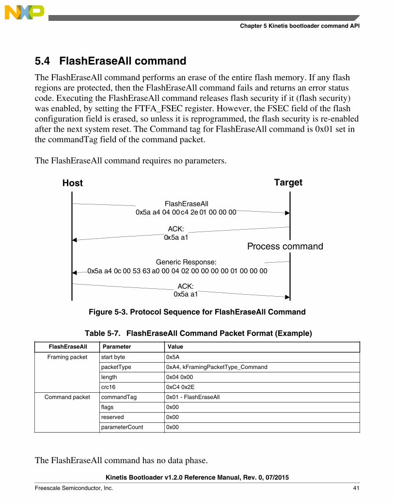
5.4 FlashEraseAll commandThe FlashEraseAll command performs an erase of the entire flash memory. If any flashregions are protected, then the FlashEraseAll command fails and returns an error statuscode. Executing the FlashEraseAll command releases flash security if it (flash security)was enabled, by setting the FTFA_FSEC register. However, the FSEC field of the flashconfiguration field is erased, so unless it is reprogrammed, the flash security is re-enabledafter the next system reset. The Command tag for FlashEraseAll command is 0x01 set inthe commandTag field of the command packet.
The FlashEraseAll command requires no parameters.
Process command
Host Target
FlashEraseAll0x5a a4 04 00 c4 2e 01 00 00 00
0x5a a4 0c 00 53 63 a0 00 04 02 00 00 00 00 01 00 00 00
ACK:0x5a a1
ACK:0x5a a1
Generic Response:
Figure 5-3. Protocol Sequence for FlashEraseAll Command
Table 5-7. FlashEraseAll Command Packet Format (Example)
FlashEraseAll Parameter Value
Framing packet start byte 0x5A
packetType 0xA4, kFramingPacketType_Command
length 0x04 0x00
crc16 0xC4 0x2E
Command packet commandTag 0x01 - FlashEraseAll
flags 0x00
reserved 0x00
parameterCount 0x00
The FlashEraseAll command has no data phase.
Chapter 5 Kinetis bootloader command API
Kinetis Bootloader v1.2.0 Reference Manual, Rev. 0, 07/2015
Freescale Semiconductor, Inc. 41
Response: The target returns a GenericResponse packet with status code either set tokStatus_Success for successful execution of the command, or set to an appropriate errorstatus code.
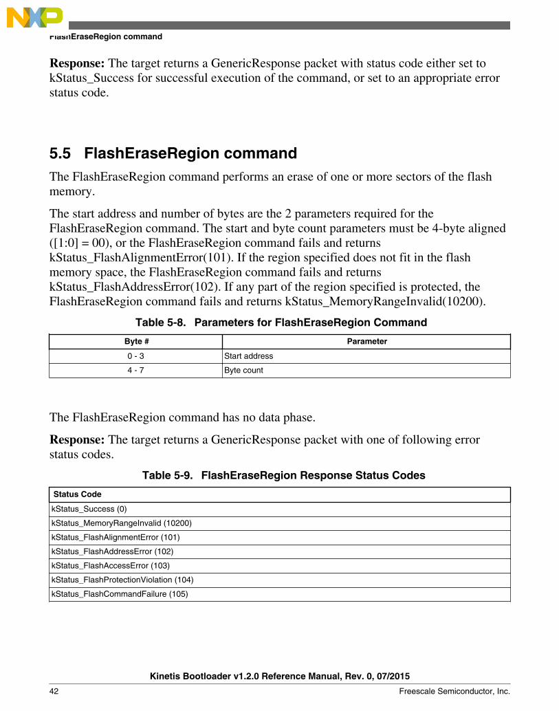
5.5 FlashEraseRegion commandThe FlashEraseRegion command performs an erase of one or more sectors of the flashmemory.
The start address and number of bytes are the 2 parameters required for theFlashEraseRegion command. The start and byte count parameters must be 4-byte aligned([1:0] = 00), or the FlashEraseRegion command fails and returnskStatus_FlashAlignmentError(101). If the region specified does not fit in the flashmemory space, the FlashEraseRegion command fails and returnskStatus_FlashAddressError(102). If any part of the region specified is protected, theFlashEraseRegion command fails and returns kStatus_MemoryRangeInvalid(10200).
Table 5-8. Parameters for FlashEraseRegion Command
Byte # Parameter
0 - 3 Start address
4 - 7 Byte count
The FlashEraseRegion command has no data phase.
Response: The target returns a GenericResponse packet with one of following errorstatus codes.
Table 5-9. FlashEraseRegion Response Status Codes
Status Code
kStatus_Success (0)
kStatus_MemoryRangeInvalid (10200)
kStatus_FlashAlignmentError (101)
kStatus_FlashAddressError (102)
kStatus_FlashAccessError (103)
kStatus_FlashProtectionViolation (104)
kStatus_FlashCommandFailure (105)
FlashEraseRegion command
Kinetis Bootloader v1.2.0 Reference Manual, Rev. 0, 07/2015
42 Freescale Semiconductor, Inc.

5.6 FlashEraseAllUnsecure commandThe FlashEraseAllUnsecure command performs a mass erase of the flash memory,including protected sectors. Flash security is immediately disabled if it (flash security)was enabled, and the FSEC byte in the flash configuration field at address 0x40C isprogrammed to 0xFE. However, if the mass erase enable option in the FSEC field isdisabled, then the FlashEraseAllUnsecure command fails.
The FlashEraseAllUnsecure command requires no parameters.
Process command
Host Target
FlashEraseAllUnsecure0x5a a4 04 00 f6 61 0d 00 cc 00
0x5a a4 0c 00 61 2c a0 00 04 02 00 00 00 00 0d 00 00 00
ACK:0x5a a1
ACK:0x5a a1
Generic Response:
Figure 5-4. Protocol Sequence for FlashEraseAll Command
Table 5-10. FlashEraseAllUnsecure Command Packet Format (Example)
FlashEraseAllUnsecure Parameter Value
Framing packet start byte 0x5A
packetType 0xA4, kFramingPacketType_Command
length 0x04 0x00
crc16 0xF6 0x61
Command packet commandTag 0x0D - FlashEraseAllUnsecure
flags 0x00
reserved 0x00
parameterCount 0x00
The FlashEraseAllUnsecure command has no data phase.
Chapter 5 Kinetis bootloader command API
Kinetis Bootloader v1.2.0 Reference Manual, Rev. 0, 07/2015
Freescale Semiconductor, Inc. 43

Response: The target returns a GenericResponse packet with status code either set tokStatus_Success for successful execution of the command, or set to an appropriate errorstatus code.
5.7 ReadMemory commandThe ReadMemory command returns the contents of memory at the given address, for aspecified number of bytes. This command can read any region of memory accessible bythe CPU and not protected by security.
The start address and number of bytes are the two parameters required for ReadMemorycommand.
Table 5-11. Parameters for read memory command
Byte Parameter Description
0-3 Start address Start address of memory to read from
4-7 Byte count Number of bytes to read and return to caller
ReadMemory command
Kinetis Bootloader v1.2.0 Reference Manual, Rev. 0, 07/2015
44 Freescale Semiconductor, Inc.
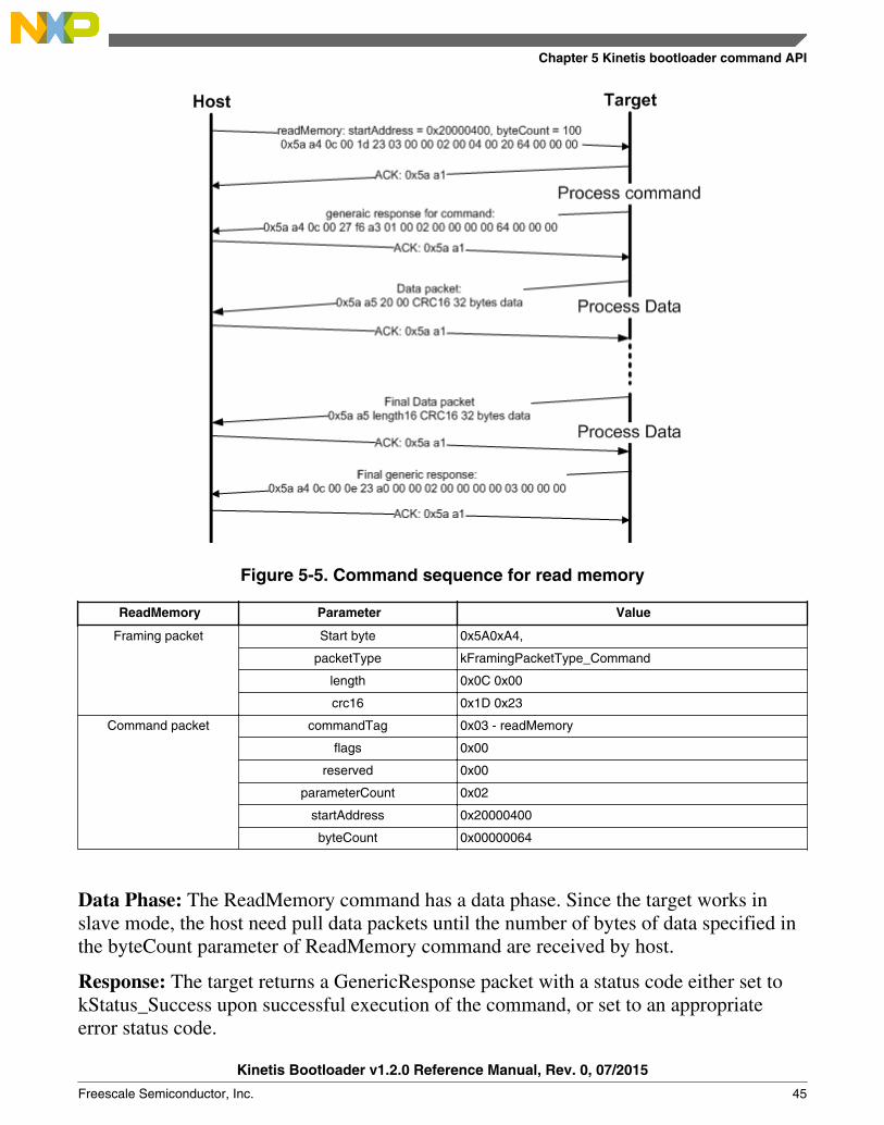
Figure 5-5. Command sequence for read memory
ReadMemory Parameter Value
Framing packet Start byte 0x5A0xA4,
packetType kFramingPacketType_Command
length 0x0C 0x00
crc16 0x1D 0x23
Command packet commandTag 0x03 - readMemory
flags 0x00
reserved 0x00
parameterCount 0x02
startAddress 0x20000400
byteCount 0x00000064
Data Phase: The ReadMemory command has a data phase. Since the target works inslave mode, the host need pull data packets until the number of bytes of data specified inthe byteCount parameter of ReadMemory command are received by host.
Response: The target returns a GenericResponse packet with a status code either set tokStatus_Success upon successful execution of the command, or set to an appropriateerror status code.
Chapter 5 Kinetis bootloader command API
Kinetis Bootloader v1.2.0 Reference Manual, Rev. 0, 07/2015
Freescale Semiconductor, Inc. 45
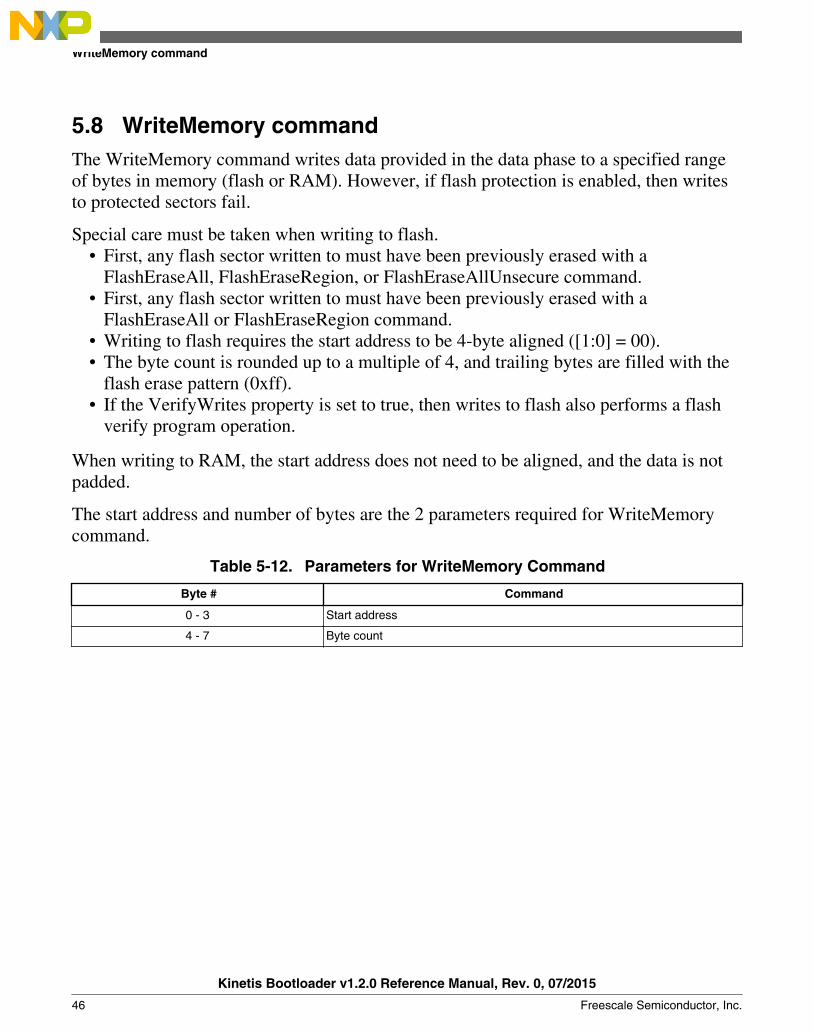
5.8 WriteMemory commandThe WriteMemory command writes data provided in the data phase to a specified rangeof bytes in memory (flash or RAM). However, if flash protection is enabled, then writesto protected sectors fail.
Special care must be taken when writing to flash.• First, any flash sector written to must have been previously erased with a
FlashEraseAll, FlashEraseRegion, or FlashEraseAllUnsecure command.• First, any flash sector written to must have been previously erased with a
FlashEraseAll or FlashEraseRegion command.• Writing to flash requires the start address to be 4-byte aligned ([1:0] = 00).• The byte count is rounded up to a multiple of 4, and trailing bytes are filled with the
flash erase pattern (0xff).• If the VerifyWrites property is set to true, then writes to flash also performs a flash
verify program operation.
When writing to RAM, the start address does not need to be aligned, and the data is notpadded.
The start address and number of bytes are the 2 parameters required for WriteMemorycommand.
Table 5-12. Parameters for WriteMemory Command
Byte # Command
0 - 3 Start address
4 - 7 Byte count
WriteMemory command
Kinetis Bootloader v1.2.0 Reference Manual, Rev. 0, 07/2015
46 Freescale Semiconductor, Inc.

Process command
Host Target
WriteMemory: startAddress = 0x20000400, byteCount = 0x640x5a a4 0c 00 06 5a 04 00 00 02 00 04 00 20 64 00 00 00
Generic Response:
ACK: 0x5a a1
ACK: 0x5a a1
Data packet :0x5a a5 20 00 CRC16 32 bytes data
Process DataACK: 0x5a a1
Final Data packet0x5a a5 length16 CRC16 32 bytes data
ACK
Process Data
Generic Response0x5a a4 0c 00 23 72 a0 00 00 02 00 00 00 00 04 00 00 00
ACK: 0x5a a1
0x5a a4 0c 00 a0 0e 04 01 00 02 00 04 00 20 40 00 00 00
Figure 5-6. Protocol Sequence for WriteMemory Command
Table 5-13. WriteMemory Command Packet Format (Example)
WriteMemory Parameter Value
Framing packet start byte 0x5A
packetType 0xA4, kFramingPacketType_Command
length 0x0C 0x00
crc16 0x06 0x5A
Command packet commandTag 0x04 - writeMemory
flags 0x00
reserved 0x00
parameterCount 0x02
startAddress 0x20000400
byteCount 0x00000064
Chapter 5 Kinetis bootloader command API
Kinetis Bootloader v1.2.0 Reference Manual, Rev. 0, 07/2015
Freescale Semiconductor, Inc. 47

Data Phase: The WriteMemory command has a data phase; the host sends data packetsuntil the number of bytes of data specified in the byteCount parameter of theWriteMemory command are received by the target.
Response: The target returns a GenericResponse packet with a status code set tokStatus_Success upon successful execution of the command, or to an appropriate errorstatus code.
5.9 FillMemory commandThe FillMemory command fills a range of bytes in memory with a data pattern. It followsthe same rules as the WriteMemory command. The difference between FillMemory andWriteMemory is that a data pattern is included in FillMemory command parameter, andthere is no data phase for the FillMemory command, while WriteMemory does have adata phase.
Table 5-14. Parameters for FillMemory Command
Byte # Command
0 - 3 Start address of memory to fill
4 - 7 Number of bytes to write with the pattern• The start address should be 32-bit aligned.• The number of bytes must be evenly divisible by 4. (Note: for a part that
uses FTFE flash, the start address should be 64-bit aligned, and thenumber of bytes must be evenly divisible by 8).
8 - 11 32-bit pattern
• To fill with a byte pattern (8-bit), the byte must be replicated 4 times in the 32-bitpattern.
• To fill with a short pattern (16-bit), the short value must be replicated 2 times in the32-bit pattern.
For example, to fill a byte value with 0xFE, the word pattern would be 0xFEFEFEFE; tofill a short value 0x5AFE, the word pattern would be 0x5AFE5AFE.
Special care must be taken when writing to flash.• First, any flash sector written to must have been previously erased with a
FlashEraseAll, FlashEraseRegion, or FlashEraseAllUnsecure command.• First, any flash sector written to must have been previously erased with a
FlashEraseAll or FlashEraseRegion command.
FillMemory command
Kinetis Bootloader v1.2.0 Reference Manual, Rev. 0, 07/2015
48 Freescale Semiconductor, Inc.
• Writing to flash requires the start address to be 4-byte aligned ([1:0] = 00).• If the VerifyWrites property is set to true, then writes to flash also performs a flash
verify program operation.
When writing to RAM, the start address does not need to be aligned, and the data is notpadded.
Process command
Host Target
FillMemory, with word pattern 0x12345678
ACK:0x5a a1
ACK:0x5a a1
Generic Response:
0x5a a4 10 00 e4 57 05 00 00 03 00 70 00 00 00 08 00 00 78 56 34 12
0x5a a4 0c 00 97 04 a0 00 00 02 00 00 00 00 05 00 00 00
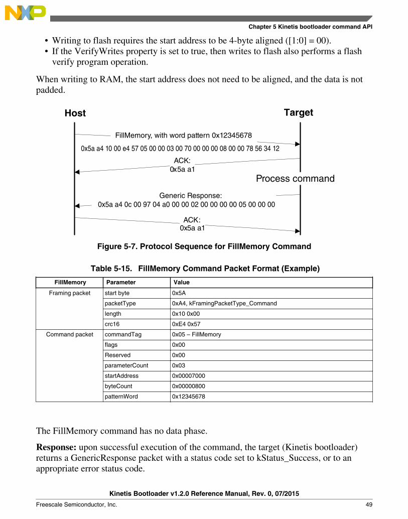
Figure 5-7. Protocol Sequence for FillMemory Command
Table 5-15. FillMemory Command Packet Format (Example)
FillMemory Parameter Value
Framing packet start byte 0x5A
packetType 0xA4, kFramingPacketType_Command
length 0x10 0x00
crc16 0xE4 0x57
Command packet commandTag 0x05 – FillMemory
flags 0x00
Reserved 0x00
parameterCount 0x03
startAddress 0x00007000
byteCount 0x00000800
patternWord 0x12345678
The FillMemory command has no data phase.
Response: upon successful execution of the command, the target (Kinetis bootloader)returns a GenericResponse packet with a status code set to kStatus_Success, or to anappropriate error status code.
Chapter 5 Kinetis bootloader command API
Kinetis Bootloader v1.2.0 Reference Manual, Rev. 0, 07/2015
Freescale Semiconductor, Inc. 49

5.10 FlashSecurityDisable commandThe FlashSecurityDisable command performs the flash security disable operation, bycomparing the 8-byte backdoor key (provided in the command) against the backdoor keystored in the flash configuration field (at address 0x400 in the flash).
The backdoor low and high words are the only parameters required forFlashSecurityDisable command.
Table 5-16. Parameters for FlashSecurityDisable Command
Byte # Command
0 - 3 Backdoor key low word
4 - 7 Backdoor key high word
Process command
Host Target
FlashSecureDisable, with backdoor key 01020304050607080x5a a4 0c 00 43 7b 06 00 00 04 03 02 01 08 07 06 05
0x5a a4 0c 00 35 78 a0 00 0c 02 00 00 00 00 06 00 00 00
ACK:0x5a a1
ACK:0x5a a1
Generic Response:
Figure 5-8. Protocol Sequence for FlashSecurityDisable Command
Table 5-17. FlashSecurityDisable Command Packet Format (Example)
FlashSecurityDisable Parameter Value
Framing packet start byte 0x5A
packetType 0xA4, kFramingPacketType_Command
length 0x0C 0x00
crc16 0x43 0x7B
Command packet commandTag 0x06 - FlashSecurityDisable
flags 0x00
reserved 0x00
Table continues on the next page...
FlashSecurityDisable command
Kinetis Bootloader v1.2.0 Reference Manual, Rev. 0, 07/2015
50 Freescale Semiconductor, Inc.
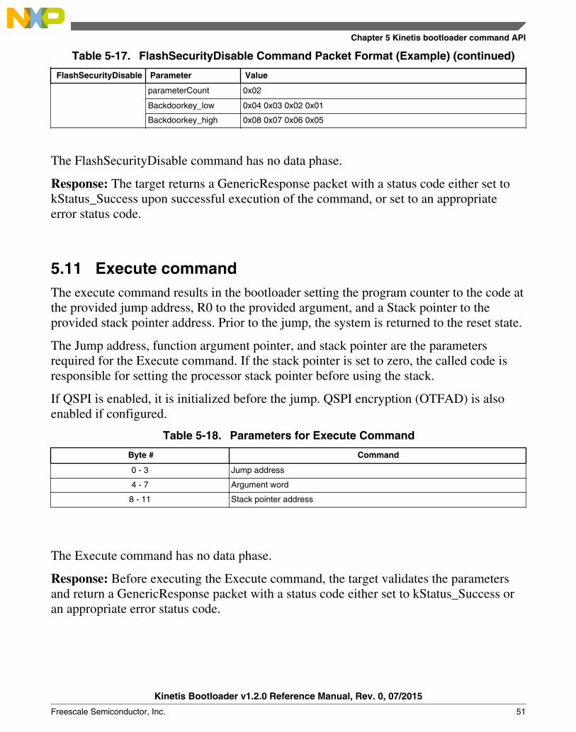
Table 5-17. FlashSecurityDisable Command Packet Format (Example) (continued)
FlashSecurityDisable Parameter Value
parameterCount 0x02
Backdoorkey_low 0x04 0x03 0x02 0x01
Backdoorkey_high 0x08 0x07 0x06 0x05
The FlashSecurityDisable command has no data phase.
Response: The target returns a GenericResponse packet with a status code either set tokStatus_Success upon successful execution of the command, or set to an appropriateerror status code.
5.11 Execute commandThe execute command results in the bootloader setting the program counter to the code atthe provided jump address, R0 to the provided argument, and a Stack pointer to theprovided stack pointer address. Prior to the jump, the system is returned to the reset state.
The Jump address, function argument pointer, and stack pointer are the parametersrequired for the Execute command. If the stack pointer is set to zero, the called code isresponsible for setting the processor stack pointer before using the stack.
If QSPI is enabled, it is initialized before the jump. QSPI encryption (OTFAD) is alsoenabled if configured.
Table 5-18. Parameters for Execute Command
Byte # Command
0 - 3 Jump address
4 - 7 Argument word
8 - 11 Stack pointer address
The Execute command has no data phase.
Response: Before executing the Execute command, the target validates the parametersand return a GenericResponse packet with a status code either set to kStatus_Success oran appropriate error status code.
Chapter 5 Kinetis bootloader command API
Kinetis Bootloader v1.2.0 Reference Manual, Rev. 0, 07/2015
Freescale Semiconductor, Inc. 51

5.12 Call commandThe Call command executes a function that is written in memory at the address sent inthe command. The address needs to be a valid memory location residing in accessibleflash (internal or external) or in RAM. The command supports the passing of one 32-bitargument. Although the command supports a stack address, at this time the call still takesplace using the current stack pointer. After execution of the function, a 32-bit return valueis returned in the generic response message.
QSPI must be initialized prior to executing the Call command if the call address is onQSPI. The Call command does not initialize QSPI.
Table 5-19. Parameters for Call Command
Byte # Command
0 - 3 Call address
4 - 7 Argument word
8 - 11 Stack pointer
Response: The target returns a GenericResponse packet with a status code either set tothe return value of the function called or set to kStatus_InvalidArgument (105).
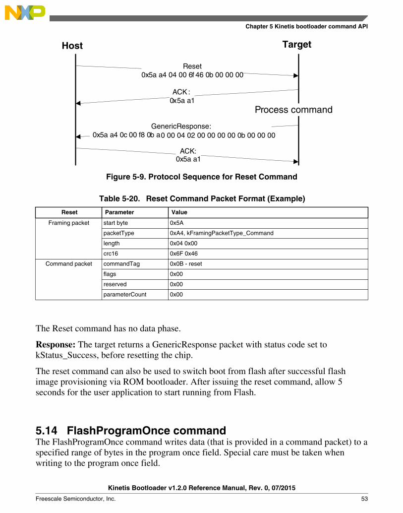
5.13 Reset commandThe Reset command results in the bootloader resetting the chip.
The Reset command requires no parameters.
Call command
Kinetis Bootloader v1.2.0 Reference Manual, Rev. 0, 07/2015
52 Freescale Semiconductor, Inc.
Process command
Host Target
Reset0x5a a4 04 00 6f 46 0b 00 00 00
GenericResponse:0x5a a4 0c 00 f8 0b a0 00 04 02 00 00 00 00 0b 00 00 00
ACK :0x5a a1
ACK:0x5a a1
Figure 5-9. Protocol Sequence for Reset Command
Table 5-20. Reset Command Packet Format (Example)
Reset Parameter Value
Framing packet start byte 0x5A
packetType 0xA4, kFramingPacketType_Command
length 0x04 0x00
crc16 0x6F 0x46
Command packet commandTag 0x0B - reset
flags 0x00
reserved 0x00
parameterCount 0x00
The Reset command has no data phase.
Response: The target returns a GenericResponse packet with status code set tokStatus_Success, before resetting the chip.
The reset command can also be used to switch boot from flash after successful flashimage provisioning via ROM bootloader. After issuing the reset command, allow 5seconds for the user application to start running from Flash.
5.14 FlashProgramOnce commandThe FlashProgramOnce command writes data (that is provided in a command packet) to aspecified range of bytes in the program once field. Special care must be taken whenwriting to the program once field.
Chapter 5 Kinetis bootloader command API
Kinetis Bootloader v1.2.0 Reference Manual, Rev. 0, 07/2015
Freescale Semiconductor, Inc. 53
• The program once field only supports programming once, so any attempted toreprogram a program once field gets an error response.
• Writing to the program once field requires the byte count to be 4-byte aligned or 8-byte aligned.
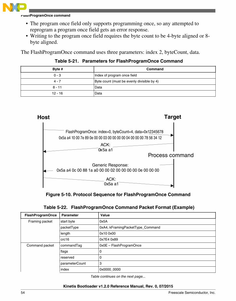
The FlashProgramOnce command uses three parameters: index 2, byteCount, data.
Table 5-21. Parameters for FlashProgramOnce Command
Byte # Command
0 - 3 Index of program once field
4 - 7 Byte count (must be evenly divisible by 4)
8 - 11 Data
12 - 16 Data
Process command
Host Target
FlashProgramOnce: index=0, byteCount=4, data=0x12345678
ACK:0x5a a1
ACK:0x5a a1
Generic Response:
0x5a a4 10 00 7e 89 0e 00 00 03 00 00 00 00 04 00 00 00 78 56 34 12
0x5a a4 0c 00 88 1a a0 00 00 02 00 00 00 00 0e 00 00 00
Figure 5-10. Protocol Sequence for FlashProgramOnce Command
Table 5-22. FlashProgramOnce Command Packet Format (Example)
FlashProgramOnce Parameter Value
Framing packet start byte 0x5A
packetType 0xA4, kFramingPacketType_Command
length 0x10 0x00
crc16 0x7E4 0x89
Command packet commandTag 0x0E – FlashProgramOnce
flags 0
reserved 0
parameterCount 3
index 0x0000_0000
Table continues on the next page...
FlashProgramOnce command
Kinetis Bootloader v1.2.0 Reference Manual, Rev. 0, 07/2015
54 Freescale Semiconductor, Inc.

Table 5-22. FlashProgramOnce Command Packet Format (Example) (continued)
FlashProgramOnce Parameter Value
byteCount 0x0000_0004
data 0x1234_5678
Response: upon successful execution of the command, the target (Kinetis bootloader)returns a GenericResponse packet with a status code set to kStatus_Success, or to anappropriate error status code.
5.15 FlashReadOnce commandThe FlashReadOnce command returns the contents of the program once field by givenindex and byte count. The FlashReadOnce command uses 2 parameters: index andbyteCount.
Table 5-23. Parameters for FlashReadOnce Command
Byte # Parameter Description
0 - 3 index Index of the program once field (to read from)
4 - 7 byteCount Number of bytes to read and return to the caller
Process command
Host Target
FlashReadOnce: index=0, byteCount=4
ACK:0x5a a1
ACK:0x5a a1
Generic Response:
0x5a a4 0c 00 c1 a5 0f 00 00 02 00 00 00 00 04 00 00 00
0x5a a4 10 00 3f 6f af 00 00 03 00 00 00 00 04 00 00 00 78 56 34 12
Figure 5-11. Protocol Sequence for FlashReadOnce Command
Chapter 5 Kinetis bootloader command API
Kinetis Bootloader v1.2.0 Reference Manual, Rev. 0, 07/2015
Freescale Semiconductor, Inc. 55
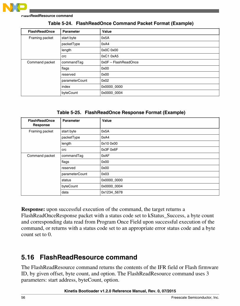
Table 5-24. FlashReadOnce Command Packet Format (Example)
FlashReadOnce Parameter Value
Framing packet start byte 0x5A
packetType 0xA4
length 0x0C 0x00
crc 0xC1 0xA5
Command packet commandTag 0x0F – FlashReadOnce
flags 0x00
reserved 0x00
parameterCount 0x02
index 0x0000_0000
byteCount 0x0000_0004
Table 5-25. FlashReadOnce Response Format (Example)
FlashReadOnceResponse
Parameter Value
Framing packet start byte 0x5A
packetType 0xA4
length 0x10 0x00
crc 0x3F 0x6F
Command packet commandTag 0xAF
flags 0x00
reserved 0x00
parameterCount 0x03
status 0x0000_0000
byteCount 0x0000_0004
data 0x1234_5678
Response: upon successful execution of the command, the target returns aFlashReadOnceResponse packet with a status code set to kStatus_Success, a byte countand corresponding data read from Program Once Field upon successful execution of thecommand, or returns with a status code set to an appropriate error status code and a bytecount set to 0.
5.16 FlashReadResource commandThe FlashReadResource command returns the contents of the IFR field or Flash firmwareID, by given offset, byte count, and option. The FlashReadResource command uses 3parameters: start address, byteCount, option.
FlashReadResource command
Kinetis Bootloader v1.2.0 Reference Manual, Rev. 0, 07/2015
56 Freescale Semiconductor, Inc.

Table 5-26. Parameters for FlashReadResource Command
Byte # Parameter Command
0 - 3 start address Start address of specific non-volatile memory to be read
4 - 7 byteCount Byte count to be read
8 - 11 option 0: IFR
1: Flash firmware ID
Process command
Host Target
ACK: 0x5a a1
ACK: 0x5a a1
Data packet
Process Data
ACK: 0x5a a1
Generic Response
ACK: 0x5a a1
FlashReadResource: start address=0, byteCount=8, option=1
5a a4 10 00 b3 cc 10 00 00 03 00 00 00 00 08 00 00 00 01 00 00 00
FlashReadResource Response5a a4 0c 00 08 d2 b0 01 00 02 00 00 00 00 08 00 00 00
5a a5 08 00 9c d3 00 08 00 00 00 01 00 06
5a a4 0c 00 75 a3 a0 00 00 02 00 00 00 00 10 00 00 00
Figure 5-12. Protocol Sequence for FlashReadResource Command
Table 5-27. FlashReadResource Command Packet Format (Example)
FlashReadResource Parameter Value
Framing packet start byte 0x5A
packetType 0xA4
length 0x10 0x00
crc 0xB3 0xCC
Command packet commandTag 0x10 – FlashReadResource
flags 0x00
Table continues on the next page...
Chapter 5 Kinetis bootloader command API
Kinetis Bootloader v1.2.0 Reference Manual, Rev. 0, 07/2015
Freescale Semiconductor, Inc. 57
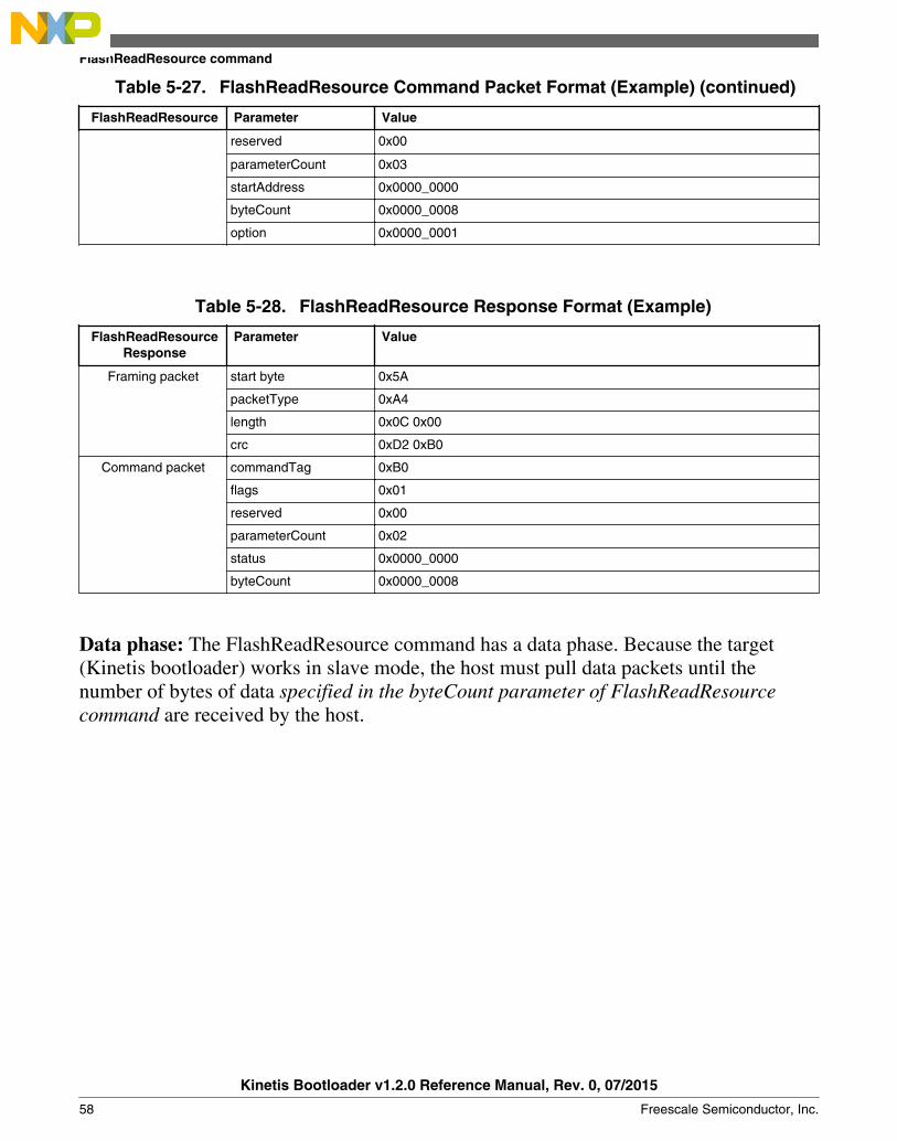
Table 5-27. FlashReadResource Command Packet Format (Example) (continued)
FlashReadResource Parameter Value
reserved 0x00
parameterCount 0x03
startAddress 0x0000_0000
byteCount 0x0000_0008
option 0x0000_0001
Table 5-28. FlashReadResource Response Format (Example)
FlashReadResourceResponse
Parameter Value
Framing packet start byte 0x5A
packetType 0xA4
length 0x0C 0x00
crc 0xD2 0xB0
Command packet commandTag 0xB0
flags 0x01
reserved 0x00
parameterCount 0x02
status 0x0000_0000
byteCount 0x0000_0008
Data phase: The FlashReadResource command has a data phase. Because the target(Kinetis bootloader) works in slave mode, the host must pull data packets until thenumber of bytes of data specified in the byteCount parameter of FlashReadResourcecommand are received by the host.
FlashReadResource command
Kinetis Bootloader v1.2.0 Reference Manual, Rev. 0, 07/2015
58 Freescale Semiconductor, Inc.
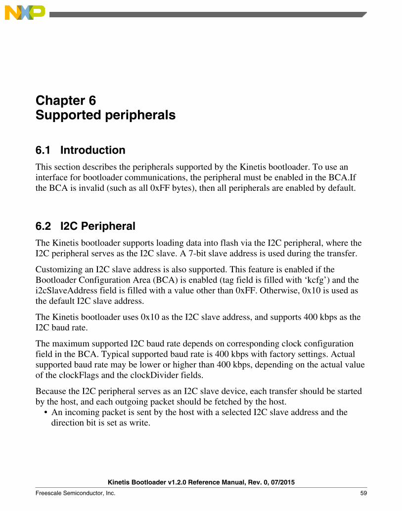
Chapter 6Supported peripherals
6.1 IntroductionThis section describes the peripherals supported by the Kinetis bootloader. To use aninterface for bootloader communications, the peripheral must be enabled in the BCA.Ifthe BCA is invalid (such as all 0xFF bytes), then all peripherals are enabled by default.
6.2 I2C PeripheralThe Kinetis bootloader supports loading data into flash via the I2C peripheral, where theI2C peripheral serves as the I2C slave. A 7-bit slave address is used during the transfer.
Customizing an I2C slave address is also supported. This feature is enabled if theBootloader Configuration Area (BCA) is enabled (tag field is filled with ‘kcfg’) and thei2cSlaveAddress field is filled with a value other than 0xFF. Otherwise, 0x10 is used asthe default I2C slave address.
The Kinetis bootloader uses 0x10 as the I2C slave address, and supports 400 kbps as theI2C baud rate.
The maximum supported I2C baud rate depends on corresponding clock configurationfield in the BCA. Typical supported baud rate is 400 kbps with factory settings. Actualsupported baud rate may be lower or higher than 400 kbps, depending on the actual valueof the clockFlags and the clockDivider fields.
Because the I2C peripheral serves as an I2C slave device, each transfer should be startedby the host, and each outgoing packet should be fetched by the host.
• An incoming packet is sent by the host with a selected I2C slave address and thedirection bit is set as write.
Kinetis Bootloader v1.2.0 Reference Manual, Rev. 0, 07/2015
Freescale Semiconductor, Inc. 59
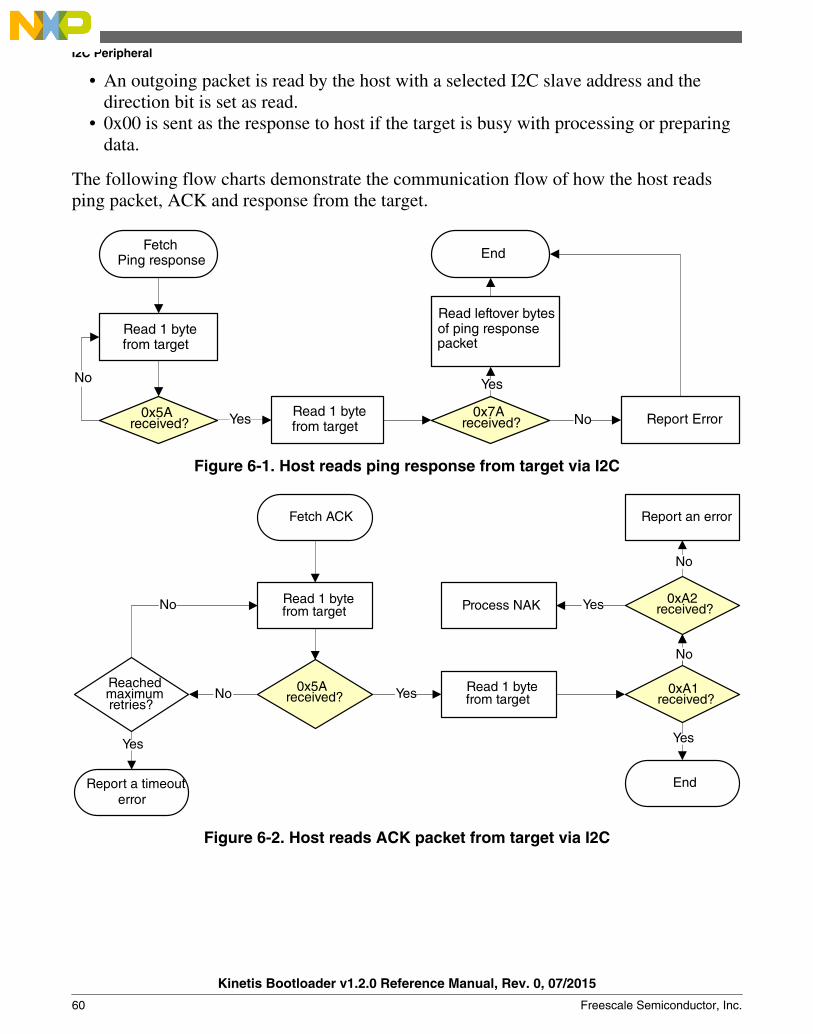
• An outgoing packet is read by the host with a selected I2C slave address and thedirection bit is set as read.
• 0x00 is sent as the response to host if the target is busy with processing or preparingdata.
The following flow charts demonstrate the communication flow of how the host readsping packet, ACK and response from the target.
Fetch Ping response
Yes
Yes
End
Report Error
No
No
Read 1 bytefrom target
0x5A received?
packet
Read leftover bytesof ping response
0x7A received?
Read 1 bytefrom target
Figure 6-1. Host reads ping response from target via I2C
Fetch ACK
No Yes
End
No
Process NAK Yes
Report an error
No
Yes
No
Reached maximum retries?
Report a timeout error
Yes
0x5A received?
0xA2 received?
0xA1 received?
Read 1 bytefrom target
Read 1 bytefrom target
Figure 6-2. Host reads ACK packet from target via I2C
I2C Peripheral
Kinetis Bootloader v1.2.0 Reference Manual, Rev. 0, 07/2015
60 Freescale Semiconductor, Inc.

Fetch Response
Yes
Yespayload length
part from target (2 bytes)
CRC checksum from target
Payload lengthless than supported
length?
Yes
payload data from target
No
Set payload length to maximum
supported lengthNo
No
Reachedmaximum
Report a timeout
Yes
End
No
(2 bytes)
Read 1 bytefrom target
0x5A received?
0xA4received?
Read 1 bytefrom target
retries?
error (End)
Read Read
Read
Figure 6-3. Host reads response from target via I2C
6.3 SPI PeripheralThe Kinetis bootloader supports loading data into flash via the SPI peripheral, where theSPI peripheral serves as a SPI slave.
Maximum supported baud rate of SPI depends on the clock configuration fields in theBootloader Configuration Area (BCA). The typical supported baud rate is 400 kbps withthe factory settings. The actual baud rate is lower or higher than 400 kbps, depending onthe actual value of the clockFlags and clockDivider fields in the BCA.
The Kinetis bootloader supports 400 kbps as the SPI baud rate.
Because the SPI peripheral serves as a SPI slave device, each transfer should be startedby the host, and each outgoing packet should be fetched by the host.
The transfer on SPI is slightly different from I2C:• Host receives 1 byte after it sends out any byte.• Received bytes should be ignored when host is sending out bytes to target• Host starts reading bytes by sending 0x00s to target• The byte 0x00 is sent as response to host if target is under the following conditions:
• Processing incoming packet• Preparing outgoing data• Received invalid data
Chapter 6 Supported peripherals
Kinetis Bootloader v1.2.0 Reference Manual, Rev. 0, 07/2015
Freescale Semiconductor, Inc. 61
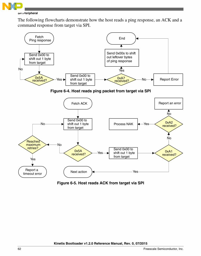
The following flowcharts demonstrate how the host reads a ping response, an ACK and acommand response from target via SPI.
Fetch Ping response
Yes
Yes
End
Report Error
No
No0x5A received?
0xA7 received?
Send 0x00 to shift out 1 bytefrom target
Send 0x00 to shift out 1 bytefrom target
Send 0x00s to shift out leftover bytesof ping response
Figure 6-4. Host reads ping packet from target via SPI
Fetch ACK
No
Yes
No
Next action
No
Process NAK Yes
Report an error
No
Yes
No
maximum
Report a timeout error
Yes
0x5Areceived?
0xA2received?
0xA1received?
Send 0x00 to shift out 1 bytefrom target
Send 0x00 to shift out 1 bytefrom target
Reached
retries?
Figure 6-5. Host reads ACK from target via SPI
SPI Peripheral
Kinetis Bootloader v1.2.0 Reference Manual, Rev. 0, 07/2015
62 Freescale Semiconductor, Inc.

Fetch Response
Yes
Yes out payload length part from target
(2 bytes)
out CRC checksum from target
Payload lengthless than supported
length?
Yes
out payload data from target
No
Set payload length to maximum
supported lengthNo
No
maximum
Report a timeout error (End)
Yes
End
No(2 bytes)
0x5Areceived?
0xA4received?
Reached
retries?
Send 0x00 to shift out 1 bytefrom target
Send 0x00 to shift out 1 bytefrom target
Write 0x00s to shift Write 0x00s to shift
Write 0x00s to shift
Figure 6-6. Host reads response from target via SPI
6.4 UART PeripheralThe Kinetis bootloader integrates an autobaud detection algorithm for the LPUARTperipheral, thereby providing flexible baud rate choices.
Autobaud feature: If LPUARTn is used to connect to the bootloader, then theLPUARTn_RX (PTB2)(PTA1) pin must be kept high and not left floating during thedetection phase in order to comply with the autobaud detection algorithm. After thebootloader detects the ping packet (0x5A 0xA6) on LPUARTn_RX, the bootloaderfirmware executes the autobaud sequence. If the baudrate is successfully detected, thenthe bootloader sends a ping packet response [(0x5A 0xA7), protocol version (4 bytes),protocol version options (2 bytes) and crc16 (2 bytes)] at the detected baudrate. TheKinetis bootloader then enters a loop, waiting for bootloader commands via the LPUARTperipheral.
NOTEThe data bytes of the ping packet must be sent continuously(with no more than 80 ms between bytes) in a fixed LPUARTtransmission mode (8-bit data, no parity bit and 1 stop bit). Ifthe bytes of the ping packet are sent one-by-one with more than80 ms delay between them, then the autobaud detection
Chapter 6 Supported peripherals
Kinetis Bootloader v1.2.0 Reference Manual, Rev. 0, 07/2015
Freescale Semiconductor, Inc. 63
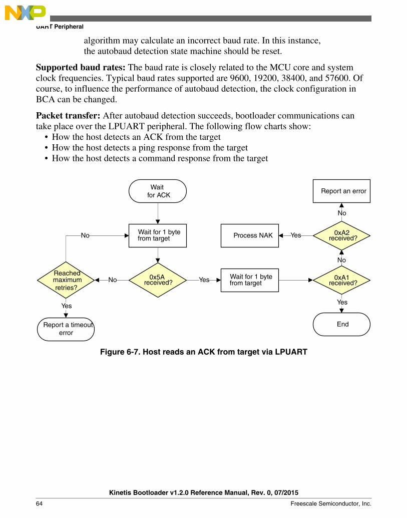
algorithm may calculate an incorrect baud rate. In this instance,the autobaud detection state machine should be reset.
Supported baud rates: The baud rate is closely related to the MCU core and systemclock frequencies. Typical baud rates supported are 9600, 19200, 38400, and 57600. Ofcourse, to influence the performance of autobaud detection, the clock configuration inBCA can be changed.
Packet transfer: After autobaud detection succeeds, bootloader communications cantake place over the LPUART peripheral. The following flow charts show:
• How the host detects an ACK from the target• How the host detects a ping response from the target• How the host detects a command response from the target
Waitfor ACK
No Yes
End
No
Process NAK Yes
Report an error
No
Yes
No
Reachedmaximum
Report a timeout error
Yes
0x5A received?
0xA2received?
0xA1 received?
Wait for 1 bytefrom target
Wait for 1 bytefrom target
retries?
Figure 6-7. Host reads an ACK from target via LPUART
UART Peripheral
Kinetis Bootloader v1.2.0 Reference Manual, Rev. 0, 07/2015
64 Freescale Semiconductor, Inc.

Wait forping response
Yes
Yes
End
Report Error
No
No
Wait for 1 bytefrom target
Wait for 1 bytefrom target
0x5A received?
0xA7 received?
Wait forremaining bytesof ping responsepacket
Figure 6-8. Host reads a ping response from target via LPUART
Waitfor response
Yes
YesWait for payload length part from target (2 bytes)
Wait for CRC checksum from
Payload lengthless than supported
length?
Yes
Wait for payload data from target
No
Set payload length to maximum
supported lengthNo
No
Reachedmaximum
Report a timeout error (End)
Yes
End
No
0x5A received?
0xA4received?
Wait for 1 bytefrom target
Wait for 1 bytefrom target
retries?
target (2 bytes)
Figure 6-9. Host reads a command response from target via LPUART
6.5 USB HID PeripheralThe Kinetis bootloader supports loading data into flash via the USB peripheral. Thetarget is implemented as a USB HID class.
USB HID does not use framing packets; instead the packetization inherent in the USBprotocol itself is used. The ability for the device to NAK Out transfers (until they can bereceived) provides the required flow control; the built-in CRC of each USB packetprovides the required error detection.
Chapter 6 Supported peripherals
Kinetis Bootloader v1.2.0 Reference Manual, Rev. 0, 07/2015
Freescale Semiconductor, Inc. 65
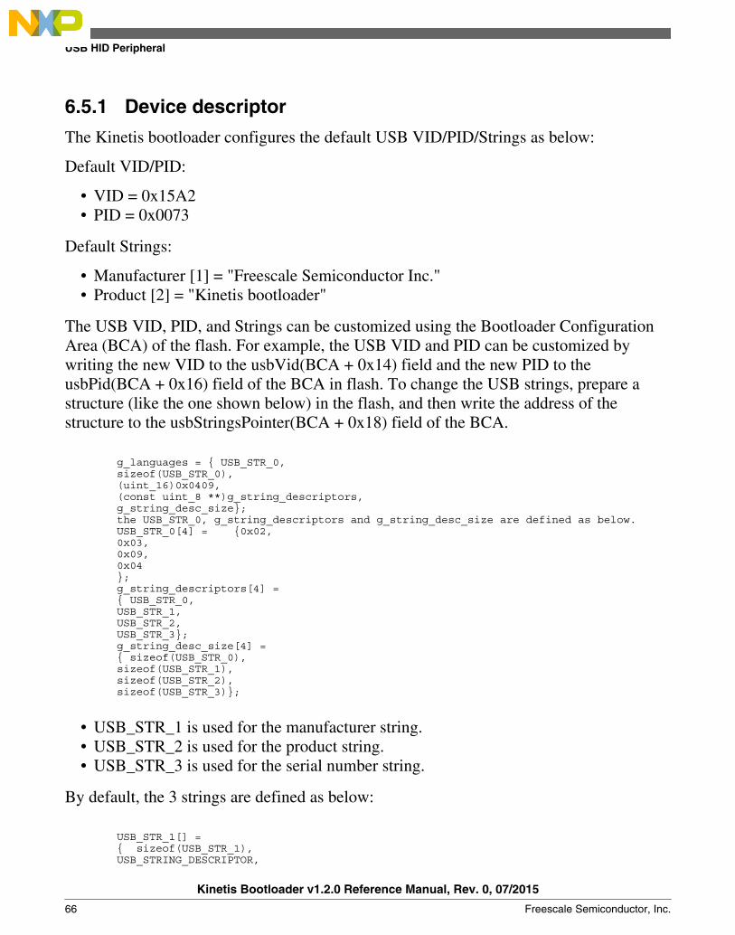
6.5.1 Device descriptor
The Kinetis bootloader configures the default USB VID/PID/Strings as below:
Default VID/PID:
• VID = 0x15A2• PID = 0x0073
Default Strings:
• Manufacturer [1] = "Freescale Semiconductor Inc."• Product [2] = "Kinetis bootloader"
The USB VID, PID, and Strings can be customized using the Bootloader ConfigurationArea (BCA) of the flash. For example, the USB VID and PID can be customized bywriting the new VID to the usbVid(BCA + 0x14) field and the new PID to theusbPid(BCA + 0x16) field of the BCA in flash. To change the USB strings, prepare astructure (like the one shown below) in the flash, and then write the address of thestructure to the usbStringsPointer(BCA + 0x18) field of the BCA.
g_languages = { USB_STR_0, sizeof(USB_STR_0), (uint_16)0x0409, (const uint_8 **)g_string_descriptors, g_string_desc_size}; the USB_STR_0, g_string_descriptors and g_string_desc_size are defined as below. USB_STR_0[4] = {0x02, 0x03, 0x09, 0x04 }; g_string_descriptors[4] = { USB_STR_0, USB_STR_1, USB_STR_2, USB_STR_3}; g_string_desc_size[4] = { sizeof(USB_STR_0), sizeof(USB_STR_1), sizeof(USB_STR_2), sizeof(USB_STR_3)};
• USB_STR_1 is used for the manufacturer string.• USB_STR_2 is used for the product string.• USB_STR_3 is used for the serial number string.
By default, the 3 strings are defined as below:
USB_STR_1[] = { sizeof(USB_STR_1), USB_STRING_DESCRIPTOR,
USB HID Peripheral
Kinetis Bootloader v1.2.0 Reference Manual, Rev. 0, 07/2015
66 Freescale Semiconductor, Inc.
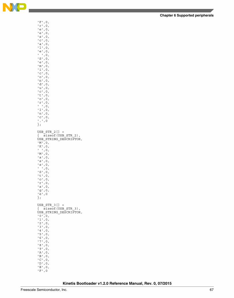
'F',0, 'r',0, 'e',0, 'e',0, 's',0, 'c',0, 'a',0, 'l',0, 'e',0, ' ',0, 'S',0, 'e',0, 'm',0, 'i',0, 'c',0, 'o',0, 'n',0, 'd',0, 'u',0, 'c',0, 't',0, 'o',0, 'r',0, ' ',0, 'I',0, 'n',0, 'c',0, '.',0 }; USB_STR_2[] = { sizeof(USB_STR_2), USB_STRING_DESCRIPTOR, 'M',0, 'K',0, ' ',0, 'M',0, 'a',0, 's',0, 's',0, ' ',0, 'S',0, 't',0, 'o',0, 'r',0, 'a',0, 'g',0, 'e',0 }; USB_STR_3[] = { sizeof(USB_STR_3), USB_STRING_DESCRIPTOR, '0',0, '1',0, '2',0, '3',0, '4',0, '5',0, '6',0, '7',0, '8',0, '9',0, 'A',0, 'B',0, 'C',0, 'D',0, 'E',0, 'F',0
Chapter 6 Supported peripherals
Kinetis Bootloader v1.2.0 Reference Manual, Rev. 0, 07/2015
Freescale Semiconductor, Inc. 67
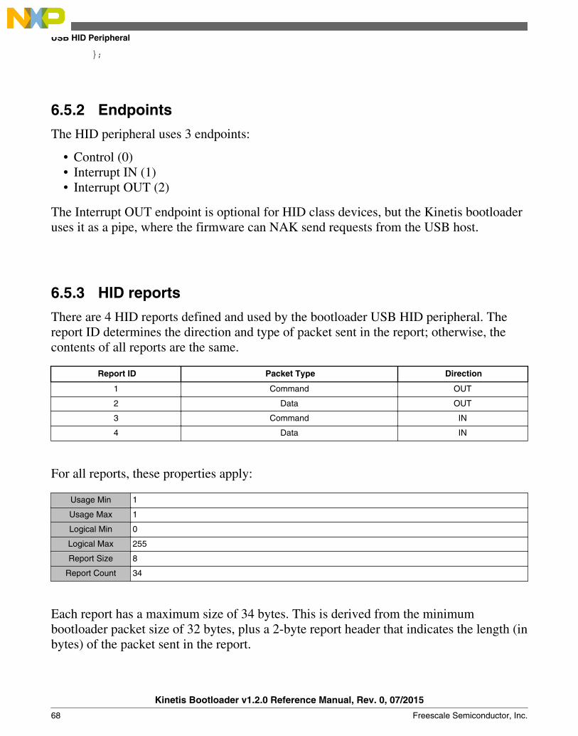
};
6.5.2 Endpoints
The HID peripheral uses 3 endpoints:
• Control (0)• Interrupt IN (1)• Interrupt OUT (2)
The Interrupt OUT endpoint is optional for HID class devices, but the Kinetis bootloaderuses it as a pipe, where the firmware can NAK send requests from the USB host.
6.5.3 HID reports
There are 4 HID reports defined and used by the bootloader USB HID peripheral. Thereport ID determines the direction and type of packet sent in the report; otherwise, thecontents of all reports are the same.
Report ID Packet Type Direction
1 Command OUT
2 Data OUT
3 Command IN
4 Data IN
For all reports, these properties apply:
Usage Min 1
Usage Max 1
Logical Min 0
Logical Max 255
Report Size 8
Report Count 34
Each report has a maximum size of 34 bytes. This is derived from the minimumbootloader packet size of 32 bytes, plus a 2-byte report header that indicates the length (inbytes) of the packet sent in the report.
USB HID Peripheral
Kinetis Bootloader v1.2.0 Reference Manual, Rev. 0, 07/2015
68 Freescale Semiconductor, Inc.

NOTEIn the future, the maximum report size may be increased, tosupport transfers of larger packets. Alternatively, additionalreports may be added with larger maximum sizes.
The actual data sent in all of the reports looks like:
0 Report ID
1 Packet Length LSB
2 Packet Length MSB
3 Packet[0]
4 Packet[1]
5 Packet[2]
...
N+3-1 Packet[N-1]
This data includes the Report ID, which is required if more than one report is defined inthe HID report descriptor. The actual data sent and received has a maximum length of 35bytes. The Packet Length header is written in little-endian format, and it is set to the size(in bytes) of the packet sent in the report. This size does not include the Report ID or thePacket Length header itself. During a data phase, a packet size of 0 indicates a data phaseabort request from the receiver.
6.6 FlexCAN PeripheralThe Kinetis Bootloader in MA512P ROM supports loading data into flash via theFlexCAN peripheral.
It supports 5 predefined speeds on FlexCAN transferring:
• 125 KHz• 250 KHz• 500 KHz• 750 KHz• 1 MHz
The curent FlexCAN IP can support up to 1 MHz speed, so the default speed is set to 1MHz.
In host applications, the user can specify the speed for FlexCAN by providing the speedindex as 0 through 4, which represents those 5 speeds.
Chapter 6 Supported peripherals
Kinetis Bootloader v1.2.0 Reference Manual, Rev. 0, 07/2015
Freescale Semiconductor, Inc. 69

In bootloader, this supports the auto speed detection feature within supported speeds. Inthe beginning, the bootloader enters the listen mode with the initial speed (default speed 1MHz). Once the host starts sending a ping to a specific node, it generates traffic on theFlexCAN bus. Since the bootloader is in a listen mode. It is able to check if the localnode speed is correct by detecting errors. If there is an error, some traffic will be visible,but it may not be on the right speed to see the real data. If this happens, the speed settingchanges and checks for errors again. No error means the speed is correct. The settingschange back to the normal receiving mode to see if there is a package for this node. Itthen stays in this speed until another host is using another speed and try to communicatewith any node. It repeats the process to detect a right speed before sending host timeoutand aborting the request.
The host side should have a reasonable time tolderance during the auto speed detectperiod. If it sends as timeout, it means there is no response from the specific node, orthere is a real error and it needs to report the error to the application.
This flow chart demonstrates the communication flow for how the host reads the pingpacket, ACK, and response from the target.
Figure 6-10. Host reads ping response from target via FlexCAN
FlexCAN Peripheral
Kinetis Bootloader v1.2.0 Reference Manual, Rev. 0, 07/2015
70 Freescale Semiconductor, Inc.
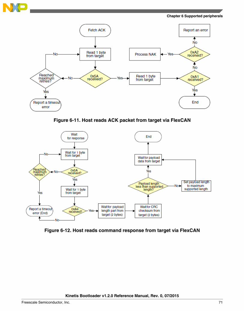
Figure 6-11. Host reads ACK packet from target via FlexCAN
Figure 6-12. Host reads command response from target via FlexCAN
Chapter 6 Supported peripherals
Kinetis Bootloader v1.2.0 Reference Manual, Rev. 0, 07/2015
Freescale Semiconductor, Inc. 71

Chapter 7Peripheral interfaces
7.1 Introduction
The block diagram shows connections between components in teh architecture of theperipheral interface.
Figure 7-1. Components peripheral interface
In this diagram, the byte and packet interfaces are shown to inherit from the controlinterface.
All peripheral drivers implement an abstract interface built on top of the driver's internalinterface. The outermost abstract interface is a packet-level interface. It returns thepayload of packets to the caller. Drivers which use framing packets have another abstractinterface layer that operates at the byte level. The abstract interfaces allow the higherlayers to use exactly the same code regardless which peripheral is being used.
Kinetis Bootloader v1.2.0 Reference Manual, Rev. 0, 07/2015
Freescale Semiconductor, Inc. 73

The abstract packet interface feeds into the command and data packet processor. Thiscomponent interprets the packets returned by the lower layer as command or datapackets.
7.2 Abstract control interface
This control interface provides a common method to initialize and shutdown peripheraldrivers. It also provides the means to perform the active peripheral detection. No datatransfer functionality is provided by this interface. That is handled by the interfaces thatinherit the control interface.
The main reason this interface is separated out from the byte and packet interfaces is toshow the commonality between the two. It also allows the driver to provide a singlecontrol interface structure definition that can be easily shared.
struct BoatloaderInitInfo{ void * contextArea; //!< Pointer to memory region for use by the driver. uint32_t available; //!< Size of the memory region the driver can use. uint32_t used; //!< Actual number of bytes used by the driver (filled in by the driver).};
struct PeripheralDescriptor { //! @brief Bit mask identifying the peripheral type. //! //! See #_peripheral_types for a list of valid bits. uint32_t typeMask;
//! @brief The instance number of the peripheral. uint32_t instance;
//! @brief Control interface for the peripheral. const peripheral_control_interface_t * controlInterface;
//! @brief Byte-level interface for the peripheral. //! //! May be NULL since not all periperhals support this interface. const peripheral_byte_inteface_t * byteInterface;
//! @brief Packet level interface for the peripheral. const peripheral_packet_interface_t * packetInterface;};
struct PeripheralControlInterface{ status_t (*minimalInit)(const PeripheralDescriptor * self, BoatloaderInitInfo * info); void (*minimalShutdown)(const PeripheralDescriptor * self); bool (*pollForActivity)(const PeripheralDescriptor * self);
Abstract control interface
Kinetis Bootloader v1.2.0 Reference Manual, Rev. 0, 07/2015
74 Freescale Semiconductor, Inc.
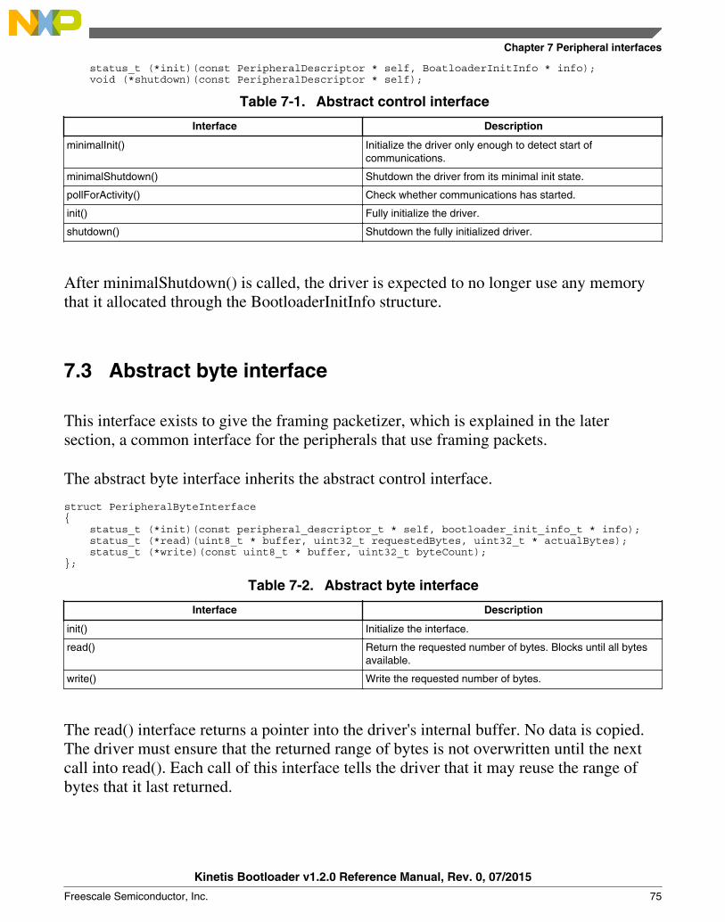
status_t (*init)(const PeripheralDescriptor * self, BoatloaderInitInfo * info); void (*shutdown)(const PeripheralDescriptor * self);
Table 7-1. Abstract control interface
Interface Description
minimalInit() Initialize the driver only enough to detect start ofcommunications.
minimalShutdown() Shutdown the driver from its minimal init state.
pollForActivity() Check whether communications has started.
init() Fully initialize the driver.
shutdown() Shutdown the fully initialized driver.
After minimalShutdown() is called, the driver is expected to no longer use any memorythat it allocated through the BootloaderInitInfo structure.
7.3 Abstract byte interface
This interface exists to give the framing packetizer, which is explained in the latersection, a common interface for the peripherals that use framing packets.
The abstract byte interface inherits the abstract control interface.
struct PeripheralByteInterface{ status_t (*init)(const peripheral_descriptor_t * self, bootloader_init_info_t * info); status_t (*read)(uint8_t * buffer, uint32_t requestedBytes, uint32_t * actualBytes); status_t (*write)(const uint8_t * buffer, uint32_t byteCount);};
Table 7-2. Abstract byte interface
Interface Description
init() Initialize the interface.
read() Return the requested number of bytes. Blocks until all bytesavailable.
write() Write the requested number of bytes.
The read() interface returns a pointer into the driver's internal buffer. No data is copied.The driver must ensure that the returned range of bytes is not overwritten until the nextcall into read(). Each call of this interface tells the driver that it may reuse the range ofbytes that it last returned.
Chapter 7 Peripheral interfaces
Kinetis Bootloader v1.2.0 Reference Manual, Rev. 0, 07/2015
Freescale Semiconductor, Inc. 75

7.4 Abstract packet interface
The abstract packet interface inherits the abstract control interface.
struct PeripheralPacketInterface{ status_t (*init)(const PeripheralDescriptor * self, BoatloaderInitInfo * info); status_t (*readPacket)(const PeripheralDescriptor * self, uint8_t ** packet, uint32_t * packetLength, packet_type_t packetType); status_t (*writePacket)(const PeripheralDescriptor * self, const uint8_t * packet, uint32_t byteCount, packet_type_t packetType); void (*abortDataPhase)(const PeripheralDescriptor * self); status_t (*finalize)(const PeripheralDescriptor * self); uint32_t (*getCurrentMaxBufferSize)(const PeripheralDescriptor * self); status_t (*requestNewMaxBufferSize)(const PeripheralDescriptor * self, uint32_t newBufferSize);};
Table 7-3. Abstract packet interface
Interface Description
init() Initialize the peripheral.
readPacket() Read a full packet from the peripheral.
writePacket() Send a complete packet out the peripheral.
abortDataPhase() Abort receiving of data packets.
finalize() Shut down the peripheral when done with use.
getCurrentMaxBufferSize() Returns the current maximum buffer size.
requestNewMaxBufferSize() Requests to set a new maximum buffer size.
7.5 Framing packetizer
The framing packetizer processes framing packets received via the byte interface withwhich it talks. It builds and validates a framing packet as it reads bytes. And it constructsoutgoing framing packets as needed to add flow control information and command ordata packets. The framing packet also supports data phase abort.
7.6 USB HID packetizer
Abstract packet interface
Kinetis Bootloader v1.2.0 Reference Manual, Rev. 0, 07/2015
76 Freescale Semiconductor, Inc.

The USB HID packetizer implements the abstract packet interface for USB HID, takingadvantage of the USB's inherent flow control and error detection capabilities. The USBHID packetizer provides a link layer that supports variable length packets and data phaseabort.
7.7 Command/data processor
This component reads complete packets from the abstract packet interface, and interpretsthem as either command packets or data packets. The actual handling of each commandis done by command handlers called by the command processor. The command handlertells the command processor whether a data phase is expected and how much data it isexpected to receive.
If the command/data processor receives a unexpected command or data packet, it ignoresit. In this instance, the communications link resynchronizes upon reception of the nextvalid command.
Chapter 7 Peripheral interfaces
Kinetis Bootloader v1.2.0 Reference Manual, Rev. 0, 07/2015
Freescale Semiconductor, Inc. 77

Chapter 8Memory interface
8.1 Abstract interface
The bootloader uses a common, abstract interface to implement the memory read/write/fill commands. This is to keep the command layer from having to know the details of thememory map and special routines.
This shared memory interface structure is used for both the high-level abstract interface,as well as low-level entries in the memory map.
struct MemoryInterface{ status_t (*init)(void); status_t (*read)(uint32_t address, uint32_t length, uint8_t * buffer); status_t (*write)(uint32_t address, uint32_t length, const uint8_t * buffer); status_t (*fill)(uint32_t address, uint32_t length, uint32_t pattern); status_t (*flush)(void); status_t (*erase)(uint32_t address, uint32_t length)}
The global bootloader context contains a pointer to the high-level abstract memoryinterface, which is one of the MemoryInterface structures. The internal implementation ofthis abstract interface uses a memory map table, referenced from the global bootloadercontext that describes the various regions of memory that are accessible and providesregion-specific operations.
The high-level functions are implemented to iterate over the memory map entries until itfinds the entry for the specified address range. Read and write operations are notpermitted to cross region boundaries, and an error is returned if such an attempt is made.
The BootloaderContext::memoryMap member is set to an array of these structures:
struct MemoryMapEntry{ uint32_t startAddress; uint32_t endAddress; const MemoryInterface * interface;};
Kinetis Bootloader v1.2.0 Reference Manual, Rev. 0, 07/2015
Freescale Semiconductor, Inc. 79
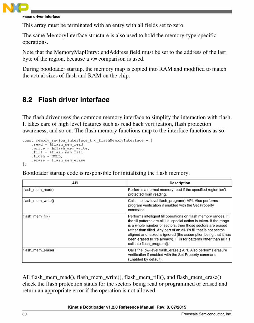
This array must be terminated with an entry with all fields set to zero.
The same MemoryInterface structure is also used to hold the memory-type-specificoperations.
Note that the MemoryMapEntry::endAddress field must be set to the address of the lastbyte of the region, because a <= comparison is used.
During bootloader startup, the memory map is copied into RAM and modified to matchthe actual sizes of flash and RAM on the chip.
8.2 Flash driver interface
The flash driver uses the common memory interface to simplify the interaction with flash.It takes care of high level features such as read back verification, flash protectionawareness, and so on. The flash memory functions map to the interface functions as so:
const memory_region_interface_t g_flashMemoryInterface = { .read = &flash_mem_read, .write = &flash_mem_write, .fill = &flash_mem_fill, .flush = NULL, .erase = flash_mem_erase};
Bootloader startup code is responsible for initializing the flash memory.
API Description
flash_mem_read() Performs a normal memory read if the specified region isn'tprotected from reading.
flash_mem_write() Calls the low-level flash_program() API. Also performsprogram verification if enabled with the Set Propertycommand.
flash_mem_fill() Performs intelligent fill operations on flash memory ranges. Ifthe fill patterns are all 1's, special action is taken. If the rangeis a whole number of sectors, then those sectors are erasedrather than filled. Any part of an all-1's fill that is not sector-aligned and -sized is ignored (the assumption being that it hasbeen erased to 1's already). Fills for patterns other than all 1'scall into flash_program().
flash_mem_erase() Calls the low-level flash_erase() API. Also performs erasureverification if enabled with the Set Property command(Enabled by default).
All flash_mem_read(), flash_mem_write(), flash_mem_fill(), and flash_mem_erase()check the flash protection status for the sectors being read or programmed or erased andreturn an appropriate error if the operation is not allowed.
Flash driver interface
Kinetis Bootloader v1.2.0 Reference Manual, Rev. 0, 07/2015
80 Freescale Semiconductor, Inc.

8.3 Low level flash driver
The low level flash driver (LLFD) handles erase and write operations on a word basis. Itcannot perform writes of less than a full word.
Bootloader startup code is responsible for initializing and shutting down the LLFD.
status_t flash_init();status_t flash_erase_all(, uint32_t key);status_t flash_erase(uint32_t start, uint32_t lengthInBytes, uint32_t key);status_t flash_program(uint32_t start, uint32_t * src, uint32_t lengthInBytes);status_t flash_get_security_state(flash_security_state_t * state);status_t flash_security_bypass(const uint8_t * backdoorKey);status_t flash_verify_erase_all(flash_margin_value_t * margin);status_t flash_verify_erase(uint32_t start, uint32_t lengthInBytes, flash_margin_value_t margin);status_t flash_verify_program(uint32_t start, uint32_t lengthInBytes, const uint8_t * expectedData, flash_margin_value_t margin, uint32_t failedAddress, uint8_t *failedData);status_t flash_is_region_protected(uint32_t start, uint32_t lengthInBytes, flash_protection_state_t * protection_state)status_t flash_get_property(flash_property_t whichProperty, uint32_t * value)status_t flash_program_once(flash_driver_t * driver, uint32_t index, uint32_t * src, uint32_t lengthInBytes);
status_t flash_read_once(flash_driver_t * driver, uint32_t index, uint32_t *dst, uint32_t lengthInBytes);
status_t flash_read_resource(flash_driver_t * driver, uint32_t start, uint32_t *dst, uint32_t lengthInBytes, flash_read_resource_option_t option);
Chapter 8 Memory interface
Kinetis Bootloader v1.2.0 Reference Manual, Rev. 0, 07/2015
Freescale Semiconductor, Inc. 81

Low level flash driver
Kinetis Bootloader v1.2.0 Reference Manual, Rev. 0, 07/2015
82 Freescale Semiconductor, Inc.

Chapter 9Kinetis Flash Driver API
9.1 Introduction
The main purpose of these APIs is to simplify the use of flash driver APIs exported fromKinetis bootloader ROM. With APIs, the user does not need to care about the differencesamong various version of flash drivers.
A set of parameters are required to ensure all APIs work properly.
This section describes how to use each flash driver API proivded in the Kinetis flashdriver API tree.
For all flash driver APIs require the driver parameter.
9.2 Flash driver data structures
9.2.1 flash_driver_t
The flash_driver_t data structure is a required argument for al flash driver APIs. It can beinitialized by calling flash_init API. For other APIs, an initialized instances of this datastructure should be passed as an argument.
Table 9-1. Definition of flash_driver_t
Offset Size Field Description
0 4 PFlashBlockBase Base address of the firstPFlash block.
4 4 PFlashTotalSize Size of all combined PFlashblock.
Table continues on the next page...
Kinetis Bootloader v1.2.0 Reference Manual, Rev. 0, 07/2015
Freescale Semiconductor, Inc. 83

Table 9-1. Definition of flash_driver_t (continued)
Offset Size Field Description
8 4 PFlashBlockCount Number of PFlash blocks.
12 4 PFlashSectorSize Size in bytes of sector ofPFlash.
16 4 PFlashCallback Pointer to a callback functionused to do extra operationsduring erasure. For example,service watchdog.
20 4 PFlashAccessSegmentSize Size of FAC access segment.
24 4 PFlashAccessSegmentCount Count of FAC accesssegment.
9.3 Flash driver API
This section describes each API supported in the flash driver API tree.
9.3.1 flash_init
This API checks and initializes the Flash module for the other Flash APIs. It must bealways called before calling other APIs.
Prototype:
status_t flash_init(flash_driver_t * driver);
Table 9-2. Parameters
Parameter Description
driver Driver Pointer to storage for the driver runtime state.
Table 9-3. Possible status response
Value Constant Description
4 kStatus_InvalidArgument Driver is NULL.
100 kStatus_FlashSizeError Returned flash is incorrect.
0 kStatus_Success This function is successfully performed.
Example:
Flash driver API
Kinetis Bootloader v1.2.0 Reference Manual, Rev. 0, 07/2015
84 Freescale Semiconductor, Inc.

flash_driver_t flashInstance;status_t status = flash_init(&flashInstance);
9.3.2 flash_erase_all
This API erases the entire flash array.
Prototype:
status_t flash_erase_all(flash_driver_t * driver, uint32_t key);
Table 9-4. Parameters
Parameter Description
Driver Driver pointer to storage for the driver runtime state.
Key Key used to validate erase operation. Must be set to0x6B65666B.
Table 9-5. Possible status response
Value Constants Description
4 kStatus_InvalidArgument Driver is NULL.
103 kStatus_FlashAccessError Command is not available under currentmode/security.
104 kStatus_FlashProtectionViolation Any region of the program flash memoryis protected.
107 kStatus_FlashEraseKeyError Key is incorrect.
0 kStatus_Success This function is successfully performed.
Example:
status_t status = flash_erase_all(&flashInstance, kFlashEraseKey);
9.3.3 flash_erase_all_unsecure
This API erases the entire flash, including protected sectors, and restores flash tounsecured mode.
Prototype:
Chapter 9 Kinetis Flash Driver API
Kinetis Bootloader v1.2.0 Reference Manual, Rev. 0, 07/2015
Freescale Semiconductor, Inc. 85
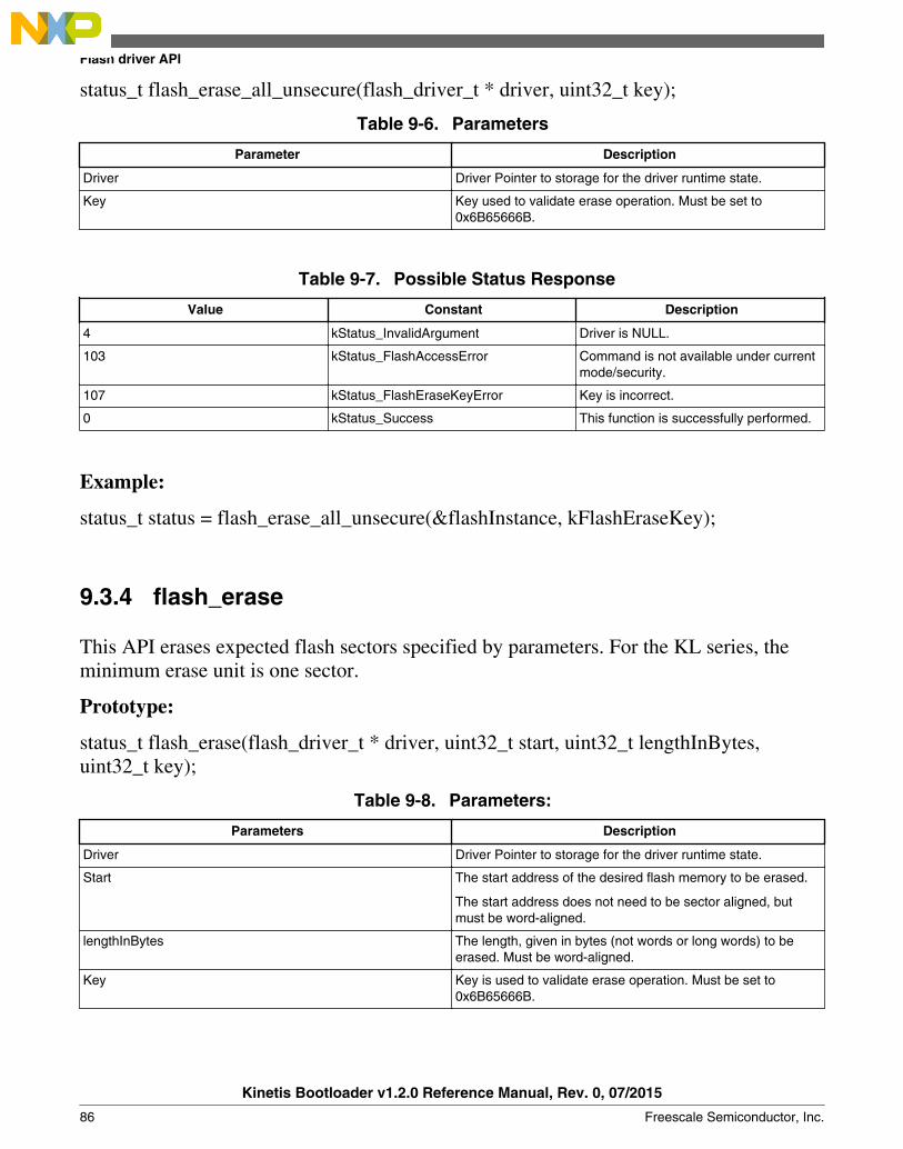
status_t flash_erase_all_unsecure(flash_driver_t * driver, uint32_t key);
Table 9-6. Parameters
Parameter Description
Driver Driver Pointer to storage for the driver runtime state.
Key Key used to validate erase operation. Must be set to0x6B65666B.
Table 9-7. Possible Status Response
Value Constant Description
4 kStatus_InvalidArgument Driver is NULL.
103 kStatus_FlashAccessError Command is not available under currentmode/security.
107 kStatus_FlashEraseKeyError Key is incorrect.
0 kStatus_Success This function is successfully performed.
Example:
status_t status = flash_erase_all_unsecure(&flashInstance, kFlashEraseKey);
9.3.4 flash_erase
This API erases expected flash sectors specified by parameters. For the KL series, theminimum erase unit is one sector.
Prototype:
status_t flash_erase(flash_driver_t * driver, uint32_t start, uint32_t lengthInBytes,uint32_t key);
Table 9-8. Parameters:
Parameters Description
Driver Driver Pointer to storage for the driver runtime state.
Start The start address of the desired flash memory to be erased.
The start address does not need to be sector aligned, butmust be word-aligned.
lengthInBytes The length, given in bytes (not words or long words) to beerased. Must be word-aligned.
Key Key is used to validate erase operation. Must be set to0x6B65666B.
Flash driver API
Kinetis Bootloader v1.2.0 Reference Manual, Rev. 0, 07/2015
86 Freescale Semiconductor, Inc.
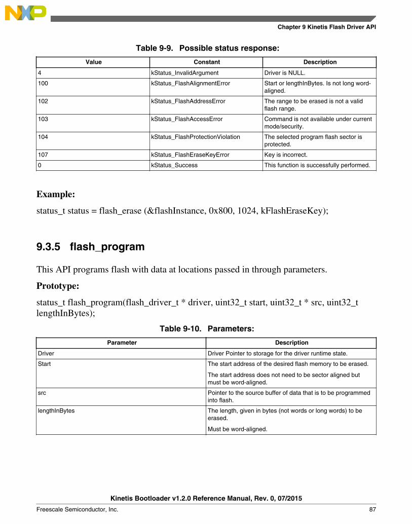
Table 9-9. Possible status response:
Value Constant Description
4 kStatus_InvalidArgument Driver is NULL.
100 kStatus_FlashAlignmentError Start or lengthInBytes. Is not long word-aligned.
102 kStatus_FlashAddressError The range to be erased is not a validflash range.
103 kStatus_FlashAccessError Command is not available under currentmode/security.
104 kStatus_FlashProtectionViolation The selected program flash sector isprotected.
107 kStatus_FlashEraseKeyError Key is incorrect.
0 kStatus_Success This function is successfully performed.
Example:
status_t status = flash_erase (&flashInstance, 0x800, 1024, kFlashEraseKey);
9.3.5 flash_program
This API programs flash with data at locations passed in through parameters.
Prototype:
status_t flash_program(flash_driver_t * driver, uint32_t start, uint32_t * src, uint32_tlengthInBytes);
Table 9-10. Parameters:
Parameter Description
Driver Driver Pointer to storage for the driver runtime state.
Start The start address of the desired flash memory to be erased.
The start address does not need to be sector aligned butmust be word-aligned.
src Pointer to the source buffer of data that is to be programmedinto flash.
lengthInBytes The length, given in bytes (not words or long words) to beerased.
Must be word-aligned.
Chapter 9 Kinetis Flash Driver API
Kinetis Bootloader v1.2.0 Reference Manual, Rev. 0, 07/2015
Freescale Semiconductor, Inc. 87

Table 9-11. Possible status response:
Value Constant Description
4 kStatus_InvalidArgument Driver or src is NULL.
101 kStatus_FlashAlignmentError Start or lengthInBytes is not longwordaligned.
102 kStatus_FlashAddressError The range to be programmed is invalid.
103 kStatus_FlashAccessError Command is not available under currentmode/security.
104 kStatus_FlashProtectionViolation The selected program flash address isprotected.
0 kStatus_Success This function is successfully performed.
Example:
uint32_t m_content[] = {0x01234567, 0x89abcdef};status_t status = flash_program (&flashInstance, 0x800, &m_content[0], sizeof(m_content));
NOTEEnsure the region to be programmed is empty and is notprotected before calling this API.
9.3.6 flash_get_security_state
This API retrieves the current flash security status, including the security enabling stateand the backdoor key enabling state.
Prototype:
status_t flash_get_security_state(flash_driver_t * driver, flash_security_state_t * state);
Table 9-12. Parameters
Parameters Description
Driver Driver Pointer to storage for the driver runtime state.
State Pointer to the value returned for the current security statuscode:
Table 9-13. Returned value
kFlashNotSecure 0 Flash is underunsecured mode.
kFlashSecureBackdoorEnabled
1 Flash is undersecured mode andBackdoor isenabled.
Flash driver API
Kinetis Bootloader v1.2.0 Reference Manual, Rev. 0, 07/2015
88 Freescale Semiconductor, Inc.

Table 9-12. Parameters
Parameters Description
Table 9-13. Returned value (continued)
kFlashSecureBackdoorDisabled
2 Flash is undersecured mode andBackdoor isdisabled.
Table 9-14. Possible status response
Value Constant Description
4 kStatus_InvalidArgument Driver or state is NULL.
0 kStatus_Success This function is successfully performed.
Example:
flash_security_state_t state;status_t status = flash_get_security_state (&flashInstance, &state);
9.3.7 flash_security_bypass
The API allows user to bypass security with a backdoor key. If the MCU is in a securedstate, this function unsecures the MCU by comparing the provided backdoor key withones in the Flash Configuration Field.
Prototype:
status_t flash_security_bypass(flash_driver_t * driver, const uint8_t * backdoorKey);
Table 9-15. Parameters
Parameter Description
Driver Driver Pointer to storage for the driver runtime state.
backdoorKey Pointer to the user buffer containing the backdoor key.
Table 9-16. Possible status response
Value Constant Description
4 kStatus_InvalidArgument Driver or backdoorKey is NULL.
103 kStatus_FlashAccessError The following condition causes thisreturn value:
Table continues on the next page...
Chapter 9 Kinetis Flash Driver API
Kinetis Bootloader v1.2.0 Reference Manual, Rev. 0, 07/2015
Freescale Semiconductor, Inc. 89

Table 9-16. Possible status response (continued)
Value Constant Description
1. An incorrect backdoor key issupplied
2. Backdoor key access has notbeen enabled.
0 kStatus_Success This function is successfully performed.
Example:
Assume that flash range from 0x400 to 0x40c contains following content after last reset,which means that backdoor key is valid and backdoor key access has been enabled.
0x11 0x22 0x33 0x44 0x55 0x66 0x77 0x88 0xff 0xff 0xff 0xbf.
uint8_t backdoorKey[] = {0x11, 0x22, 0x33, 0x44, 0x55, 0x66, 0x77, 0x88};status_t status = flash_security_bypass (&flashInstance, & backdoorKey[0]);
9.3.8 flash_verify_erase_all
This API checks if the entire flash has been erased to the specified read margin level.
This API is often called after executing flash_erase_all in order to verify if the entireflash has been fully erased.
Prototype:
status_t flash_verify_erase_all(flash_driver_t * driver, flash_margin_value_t margin);
Table 9-17. Parameters
Parameter Description
Driver Driver Pointer to storage for the driver runtime state.
Margin1 Read margin choice as follows:
kFlashMargin_Normal 0
kFlashMargin_User 1
kFlashMargin_Factory 2
Table 9-18. Possible status response
Value Constant Description
4 kStatus_InvalidArgument Driver or backdoorKey is NULL.
103 kStatus_FlashAccessError An invalid margin choice is specified.
105 kStatus_FlashCommandFailure The entire flash is not fully erased.
0 kStatus_Success This function is successfully performed.
Flash driver API
Kinetis Bootloader v1.2.0 Reference Manual, Rev. 0, 07/2015
90 Freescale Semiconductor, Inc.

Example:
Assume that flash_erase_all has been successfully executed.
status_t status = flash_verify_erase_all (&flashInstance, kFlashMargin_User);
NOTEFor the choice of margin, see the FTFA chapter in the referencemanual for detailed information.
9.3.9 flash_verify_erase
This API verifies erasure of the desired flash area at specified margin level. This functionchecks the appropriate number of flash sectors based on the desired start address andlength to see if the flash has been erased at the specified read margin level.
This API is often called after successfully performing the flash_erase API.
Prototype:
status_t flash_verify_erase(flash_driver_t * driver, uint32_t start, uint32_t lengthInBytes,
flash_margin_value_t margin);
Table 9-19. Parameters:
Parameter Description
Driver Driver Pointer to storage for the driver runtime state.
Start The start address of the desired flash memory to be verified.
lengthInBytes The length, given in bytes (not words or long words) to beverified.
Must be word-aligned.
margin Read margin choice as follows:
kFlashMargin_Normal 0
kFlashMargin_User 1
kFlashMargin_Factory 2
Table 9-20. Possible status response:
Value Constant Description
4 kStatus_InvalidArgument Driver or backdoorKey is NULL.
101 kStatus_FlashAlignmentError Start or lengthInBytes is not longwordaligned.
Table continues on the next page...
Chapter 9 Kinetis Flash Driver API
Kinetis Bootloader v1.2.0 Reference Manual, Rev. 0, 07/2015
Freescale Semiconductor, Inc. 91
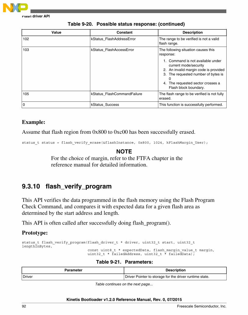
Table 9-20. Possible status response: (continued)
Value Constant Description
102 kStatus_FlashAddressError The range to be verified is not a validflash range.
103 kStatus_FlashAccessError The following situation causes thisresponse:
1. Command is not available undercurrent mode/security
2. An invalid margin code is provided3. The requested number of bytes is
04. The requested sector crosses a
Flash block boundary.
105 kStatus_FlashCommandFailure The flash range to be verified is not fullyerased.
0 kStatus_Success This function is successfully performed.
Example:
Assume that flash region from 0x800 to 0xc00 has been successfully erased.
status_t status = flash_verify_erase(&flashInstance, 0x800, 1024, kFlashMargin_User);
NOTEFor the choice of margin, refer to the FTFA chapter in thereference manual for detailed information.
9.3.10 flash_verify_program
This API verifies the data programmed in the flash memory using the Flash ProgramCheck Command, and compares it with expected data for a given flash area asdetermined by the start address and length.
This API is often called after successfully doing flash_program().
Prototype:
status_t flash_verify_program(flash_driver_t * driver, uint32_t start, uint32_t lengthInBytes, const uint8_t * expectedData, flash_margin_value_t margin, uint32_t * failedAddress, uint32_t * failedData);
Table 9-21. Parameters:
Parameter Description
Driver Driver Pointer to storage for the driver runtime state.
Table continues on the next page...
Flash driver API
Kinetis Bootloader v1.2.0 Reference Manual, Rev. 0, 07/2015
92 Freescale Semiconductor, Inc.
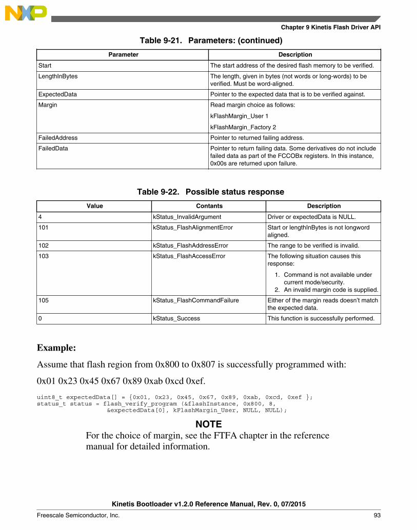
Table 9-21. Parameters: (continued)
Parameter Description
Start The start address of the desired flash memory to be verified.
LengthInBytes The length, given in bytes (not words or long-words) to beverified. Must be word-aligned.
ExpectedData Pointer to the expected data that is to be verified against.
Margin Read margin choice as follows:
kFlashMargin_User 1
kFlashMargin_Factory 2
FailedAddress Pointer to returned failing address.
FailedData Pointer to return failing data. Some derivatives do not includefailed data as part of the FCCOBx registers. In this instance,0x00s are returned upon failure.
Table 9-22. Possible status response
Value Contants Description
4 kStatus_InvalidArgument Driver or expectedData is NULL.
101 kStatus_FlashAlignmentError Start or lengthInBytes is not longwordaligned.
102 kStatus_FlashAddressError The range to be verified is invalid.
103 kStatus_FlashAccessError The following situation causes thisresponse:
1. Command is not available undercurrent mode/security.
2. An invalid margin code is supplied.
105 kStatus_FlashCommandFailure Either of the margin reads doesn’t matchthe expected data.
0 kStatus_Success This function is successfully performed.
Example:
Assume that flash region from 0x800 to 0x807 is successfully programmed with:
0x01 0x23 0x45 0x67 0x89 0xab 0xcd 0xef.
uint8_t expectedData[] = {0x01, 0x23, 0x45, 0x67, 0x89, 0xab, 0xcd, 0xef };status_t status = flash_verify_program (&flashInstance, 0x800, 8, &expectedData[0], kFlashMargin_User, NULL, NULL);
NOTEFor the choice of margin, see the FTFA chapter in the referencemanual for detailed information.
Chapter 9 Kinetis Flash Driver API
Kinetis Bootloader v1.2.0 Reference Manual, Rev. 0, 07/2015
Freescale Semiconductor, Inc. 93

9.3.11 flash_get_property
This functions returns the desired flash property. This includes base address, sector size,and other options.
Prototype:
status_t flash_get_property(flash_driver_t * driver, flash_property_t whichProperty, uint32_t
* value);
Table 9-23. Parameters
Parameter Description
Driver Driver Pointer to storage for the driver runtime state.
whichProperty The desired property from the list of properties.
Table 9-24. Properties
Definition Value Description
kFlashProperty_SectorSize 0 Get Flash Sector size.
kFlashProperty_TotalFlashSize
1 Get total flash size.
kFlashProperty_BlockCount 3 Get block count.
kFlashProperty_FlashBlockBaseAddr
4 Get flash base address.
kFlashProperty_FlashFacSupport
5 Get FAC support status.
kFlashProperty_FlashAccessSegmentSize
6 Get FAC segment size.
kFlashProperty_FlashAccessSegmentCount
7 Get FAC segment count.
kFlashProperty_Version 8 Get version of Flash DriverAPI.
Value Pointer to the value returned for the desired flash property.
Table 9-25. Possible status response
Value Constant Description
4 kStatus_InvalidArgument Driver or value is invalid.
106 kStatus_FlashUnknownProperty Invalid property is supplied.
0 kStatus_Success This function is successfully performed.
Example:
uint32_t propertyValue;status_t status = flash_get_property (&flashInstance, kFlashProperty_SectorSize,&propertyValue);
Flash driver API
Kinetis Bootloader v1.2.0 Reference Manual, Rev. 0, 07/2015
94 Freescale Semiconductor, Inc.
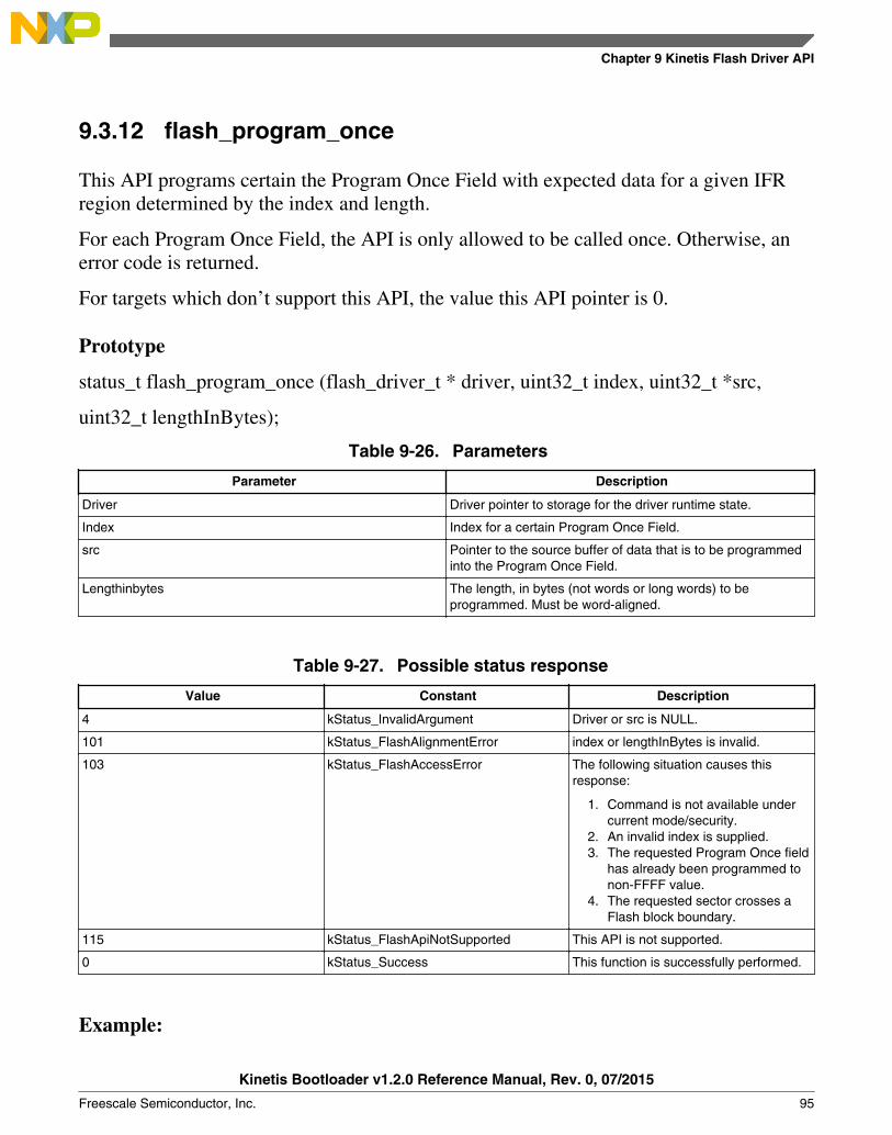
9.3.12 flash_program_once
This API programs certain the Program Once Field with expected data for a given IFRregion determined by the index and length.
For each Program Once Field, the API is only allowed to be called once. Otherwise, anerror code is returned.
For targets which don’t support this API, the value this API pointer is 0.
Prototype
status_t flash_program_once (flash_driver_t * driver, uint32_t index, uint32_t *src,
uint32_t lengthInBytes);
Table 9-26. Parameters
Parameter Description
Driver Driver pointer to storage for the driver runtime state.
Index Index for a certain Program Once Field.
src Pointer to the source buffer of data that is to be programmedinto the Program Once Field.
Lengthinbytes The length, in bytes (not words or long words) to beprogrammed. Must be word-aligned.
Table 9-27. Possible status response
Value Constant Description
4 kStatus_InvalidArgument Driver or src is NULL.
101 kStatus_FlashAlignmentError index or lengthInBytes is invalid.
103 kStatus_FlashAccessError The following situation causes thisresponse:
1. Command is not available undercurrent mode/security.
2. An invalid index is supplied.3. The requested Program Once field
has already been programmed tonon-FFFF value.
4. The requested sector crosses aFlash block boundary.
115 kStatus_FlashApiNotSupported This API is not supported.
0 kStatus_Success This function is successfully performed.
Example:
Chapter 9 Kinetis Flash Driver API
Kinetis Bootloader v1.2.0 Reference Manual, Rev. 0, 07/2015
Freescale Semiconductor, Inc. 95

Assume the Program Once Field has not been programmed before.
uint32_t expectedData = 0x78563412;
status_t status = flash_program_once(&flashInstance, 0, &expectedData, 4);
NOTEFor the choice of index and length, see the FTFA chapter in RMfor detailed information.
9.3.13 flash_read_once
This API reads certain flash Program Once Field according to parameters passed byindex and length.
For targets that do not support this API, the value of this API pointer is 0.
Prototype:
status_t flash_read_once (flash_driver_t * driver, uint32_t index, uint32_t *dst, uint32_t
lengthInBytes);
Table 9-28. Parameters
Parameter Description
Driver Driver pointer to storage for the driver runtime state.
Index Index for a certain Program Once Field.
dst Pointer to the destination buffer of data that stores data readsfrom the Program Once Field.
Lengthinbytes The length, in bytes (not words or long words) to be read.Must be word-aligned.
Table 9-29. Possible status response
Value Constant Description
4 kStatus_InvalidArgument Driver or dst is NULL.
101 kStatus_FlashAlignmentError Index or lengthInBytes is invalid.
103 kStatus_FlashAccessError The following situation causes thisresponse:
1. Command is not available undercurrent mode/security.
2. An invalid index is supplied.
115 kStatus_FlashApiNotSupported This API is not supported.
0 kStatus_Success This function is successfully performed.
Flash driver API
Kinetis Bootloader v1.2.0 Reference Manual, Rev. 0, 07/2015
96 Freescale Semiconductor, Inc.

Example:
uint32_t temp; status_t status = flash_read_once(&flashInstance, 0, &temp, 4);
NOTEFor the choice of index and length, see the FTFA chapter in RMfor detailed information.
9.3.14 flash_read_resource
This API reads certain regions of IFR determined by the start address, length, and option.
For targets that do not support this API, the value this API pointers to is 0.
Prototype:
status_t flash_read_resource(flash_driver_t * driver, uint32_t start, uint32_t *dst, uint32_t lengthInBytes, flash_read_resource_option_t option);
Table 9-30. Parameters
Parameter Description
Driver Driver pointer to storage for the driver runtime state.
Start Index for a certain Program Once Field.
dst Pointer to the destination buffer of data that stores data readsfrom IFR.
Lengthinbytes The length, in bytes (not words or long words), to be read.Must be word-aligned.
Option The resource option which indicates the area that needs beread back.
• 0 IFR
• 1 Version ID of the flash module
Table 9-31. Possible status response
Value Constant Description
4 kStatus_InvalidArgument Driver or dst is NULL.
101 kStatus_FlashAlignmentError Start, lengthInBytes, or option is invalid.
103 kStatus_FlashAccessError The following situation causes thisresponse:
1. Command is not available undercurrent mode/security.
2. An invalid index is supplied.3. An invalid resource option.
Table continues on the next page...
Chapter 9 Kinetis Flash Driver API
Kinetis Bootloader v1.2.0 Reference Manual, Rev. 0, 07/2015
Freescale Semiconductor, Inc. 97

Table 9-31. Possible status response (continued)
Value Constant Description
4. Address is out-of-rage for thetargeted resource.
5. Address is not long word aligned.
115 kStatus_FlashApiNotSupported This API is not supported.
0 kStatus_Success This function is successfully performed.
Example:
uint32_t temp[256];status_t status = tree->flashDriver-> flash_read_resource(&flashInstance, 0, &temp[0], 256, 0);
NOTESee the FTFA chapter in RM for detailed information regardingthe start, length, and option choices.
9.3.15 flash_register_callback
This API registers expected callback function into flash driver, such as function forservicing watchdog.
Prototype:
status_t flash_register_callback(flash_driver_t * driver, flash_callback_t callback);
Table 9-32. Parameters
Parameter Description
Driver Driver pointer to storage for the driver runtime state.
Callback A pointer points to a function which is called during erasure.
A usage for this function is to service watch dog during eraseoperation.
Table 9-33. Possible status response
Value Constant Description
4 kStatus_InvalidArgument Driver or dst is NULL.
115 kStatus_FlashApiNotSupported This API is not supported.
0 kStatus_Success This function is successfully performed.
Example:
Assume there is a function.
Flash driver API
Kinetis Bootloader v1.2.0 Reference Manual, Rev. 0, 07/2015
98 Freescale Semiconductor, Inc.

void led_toggle(void).status_t status = flash_register_callback (&flashInstance, led_toggle);
9.4 Integrate Wrapped Flash Driver API to actual projects
There are three steps required to integrate Wrapped Flash Driver API (WFDA) to actualprojects.
9.4.1 Add flash.h and flash_api_tree.c to corresponding project
The directory which contains flash.h should be added to include path. This imageprovides an example.
Chapter 9 Kinetis Flash Driver API
Kinetis Bootloader v1.2.0 Reference Manual, Rev. 0, 07/2015
Freescale Semiconductor, Inc. 99
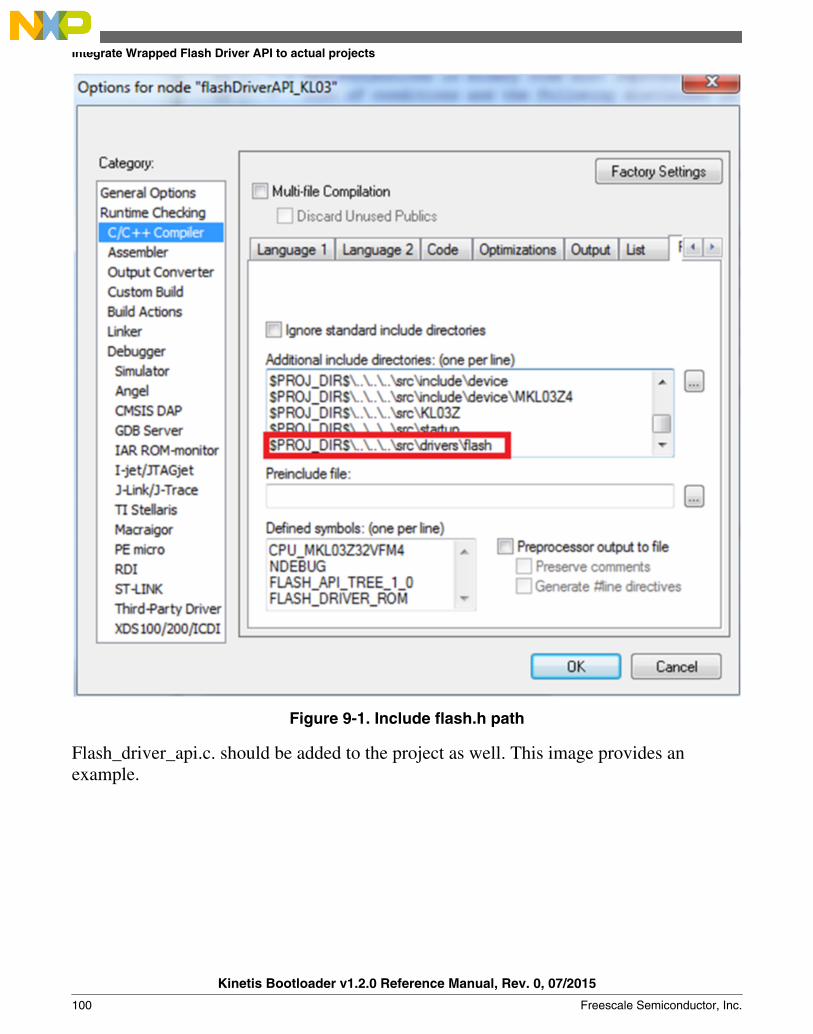
Figure 9-1. Include flash.h path
Flash_driver_api.c. should be added to the project as well. This image provides anexample.
Integrate Wrapped Flash Driver API to actual projects
Kinetis Bootloader v1.2.0 Reference Manual, Rev. 0, 07/2015
100 Freescale Semiconductor, Inc.

Figure 9-2. Add flash_drive_api.c to project
9.4.2 Include flash.h to corresponding files before calling WFDI
For detailed information, see the demos for KL03, KL43, and KL27. Both flash.h andflash_api_tree.c are attached in the demos.
Chapter 9 Kinetis Flash Driver API
Kinetis Bootloader v1.2.0 Reference Manual, Rev. 0, 07/2015
Freescale Semiconductor, Inc. 101

Chapter 10Kinetis bootloader porting
10.1 Introduction
This chapter discusses the steps required to port the Kinetis bootloader to an unsupportedKinetis MCU. Freescale is working to bring bootloader support to the entire Kinetisportfolio, but some devices still require user porting until all legacy device ports arecomplete. Each step of the porting process is discussed in detail in the following sections.
10.2 Choosing a starting point
The first step is to download the latest bootloader release. Freescale releases updates forthe bootloader multiple times per year, so having the latest package is important forfinding the best starting point for your port. To find the most recent bootloader release,freescale.com/KBOOT .
The easiest way to port the bootloader is to choose a supported target that is the closestmatch to the desired target MCU.
NOTEJust because a supported device has a similar part number to thedesired target MCU, it may not necessarily be the best startingpoint. To determine the best match, reference the data sheet andreference manual for all of the supported Kinetis devices.
10.3 Preliminary porting tasks
Kinetis Bootloader v1.2.0 Reference Manual, Rev. 0, 07/2015
Freescale Semiconductor, Inc. 103

All references to paths in the rest of this chapter are relative to the root of the extractedKinetis bootloader package. The container folder is namedFSL_Kinetis_Bootloader_<version>. Before modifying source code, the following tasksshould be performed.
10.3.1 Download device header files
The most manual process in porting the bootloader to a new target is editing the deviceheader files. This process is very time consuming and error prone, so Freescale providesCMSIS-compatible packages for all Kinetis devices that contain bootloader-compatibledevice header files. These packages can be found on the product page for the MCU.
NOTEIt is not recommended to proceed with a port if a package doesnot yet exist for the desired target MCU.
In the downloaded package, locate the folder with the header files. The folder is namedafter the MCU (for example, “MK64F12”) and contains a unique header file for eachperipheral in addition to regs.h and system_<device>.h files. Copy the entire folder intothe /src/include/device folder of the bootloader tree.
10.3.2 Copy the closest match
Copy the folder of the MCU that most closely matches the target MCU in the /targetsfolder of the bootloader source tree. Rename it to coincide with the target MCU partnumber.
Once the files are copied, browse the newly created folder. Rename all files that havereference to the device from which they were copied. The following files need to berenamed:
• clock_config_<old_device>.c —> clock_config_<new_device>.c• hardware_init_<old_device>.c —> hardware_init _<new_device>.c• memory_map_<old_device>.c —> memory_map _<new_device>.c• peripherals_<old_device>.c —> peripherals _<new_device>.c• startup_<old_device>.c —> startup _<new_device>.c
10.3.3 Provide device startup file (vector table)
Preliminary porting tasks
Kinetis Bootloader v1.2.0 Reference Manual, Rev. 0, 07/2015
104 Freescale Semiconductor, Inc.

A device-specific startup file is a key piece to the port. The bootloader may not functioncorrectly without the correct vector table. A startup file from the closest match MCU canbe used as a template, but it is strongly recommended that the file be thoroughly checkedbefore using it in the port due to differences in interrupt vector mappings between Kinetisdevices.
The startup file should be created and placed into a folder that references the target MCUand toolchain in the /src/startup folder of the bootloader source tree. Startup files arealways assembly (*.s) and are named startup_<device>.s.
10.3.4 Clean up the IAR project
This example uses the IAR tool chain for the new project. Other supported tool chainscan be used in a similar manner.
The folder copy performed in step 1.2.2 copies more than just source code files. Inside ofthe newly created /targets/<device> folder, locate the IAR workspace file(bootloader.eww) and open it. This image shows an example of what a workspace lookslike and the files that need to be touched.
Figure 10-1. IAR workspace
Chapter 10 Kinetis bootloader porting
Kinetis Bootloader v1.2.0 Reference Manual, Rev. 0, 07/2015
Freescale Semiconductor, Inc. 105

Once changes have been made, update the project to reference the target MCU. This canbe found in the project options.
Figure 10-2. Project options
10.3.5 Bootloader peripherals
There is a C/C++ preprocessor define that is used by the bootloader source to configurethe bootloader based on the target MCU. This define must be updated to reference thecorrect set of device-specific header files.
Preliminary porting tasks
Kinetis Bootloader v1.2.0 Reference Manual, Rev. 0, 07/2015
106 Freescale Semiconductor, Inc.

Figure 10-3. Options for node "freedom_bootloader"
The linker file needs to be replaced if the memory configuration of the target MCUdiffers from the closest match. This is done in the linker settings, which is also part of theproject options.
Chapter 10 Kinetis bootloader porting
Kinetis Bootloader v1.2.0 Reference Manual, Rev. 0, 07/2015
Freescale Semiconductor, Inc. 107
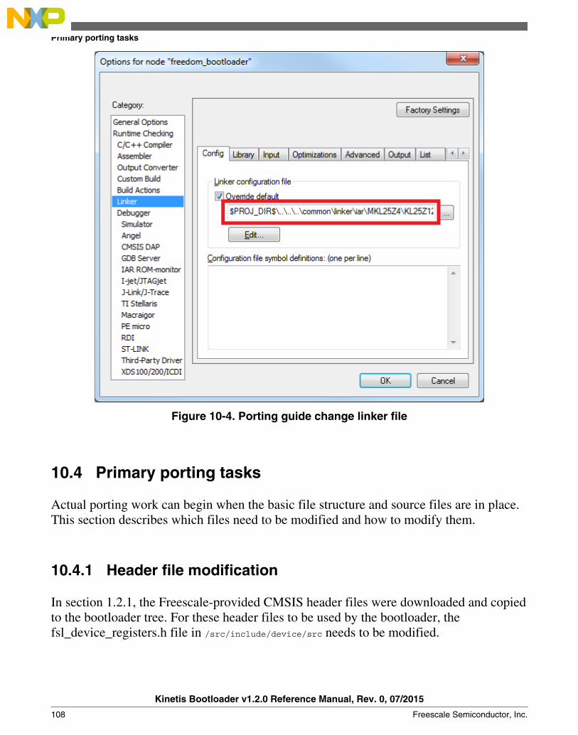
Figure 10-4. Porting guide change linker file
10.4 Primary porting tasks
Actual porting work can begin when the basic file structure and source files are in place.This section describes which files need to be modified and how to modify them.
10.4.1 Header file modification
In section 1.2.1, the Freescale-provided CMSIS header files were downloaded and copiedto the bootloader tree. For these header files to be used by the bootloader, thefsl_device_registers.h file in /src/include/device/src needs to be modified.
Primary porting tasks
Kinetis Bootloader v1.2.0 Reference Manual, Rev. 0, 07/2015
108 Freescale Semiconductor, Inc.
The file is organized by MCU family and points the bootloader to the device-specificheader files. A new #elif use case needs to be added to the bottom of the list (before the#else that indicates error) that references the target MCU. Note the define used to identifythe target MCU must match the define added in section 1.2.5, in Figure 3. With the newsection in place, reference the content used for other devices to determine what needs tobe added to the new section.
10.4.2 Bootloader peripherals
There are two steps required to enable and configure the desired peripherals on the targetMCU:
• Choosing which peripherals can be used by the bootloader.• Configuring the hardware at a low level to enable access to those peripherals.
10.4.2.1 Supported peripherals
The bootloader uses the peripherals_<device>.c file to define which peripheral interfacesare active in the bootloader. The source file itself includes a single table, g_peripherals[],that contains active peripheral information and pointers to configuration structures. Thisfile is found in /targets/<device>/src.
It’s important to only place configurations for peripherals that are present on the targetMCU. Otherwise, the processor generates fault conditions when trying to initialize aperipheral that is not physically present.
In terms of the content of each entry in the g_peripherals[] table, it is recommended toreuse existing entries and only modify the .instance member. For example, starting withthe following UART0 member, it can be changed to UART1 by simplychanging .instance from “0” to “1”.
{ .typeMask = kPeripheralType_UART, .instance = 0, .pinmuxConfig = uart_pinmux_config, .controlInterface = &g_scuartControlInterface; .byteInterface = &g_scuartByteInterfacek; .packetInterface = &g_framingPacketInterface; }
When the table has all required entries, it must be terminated with a null { 0 } entry.
10.4.2.2 Peripheral initialization
Chapter 10 Kinetis bootloader porting
Kinetis Bootloader v1.2.0 Reference Manual, Rev. 0, 07/2015
Freescale Semiconductor, Inc. 109

Once the desired peripheral configuration has been selected, the low level initializationmust be accounted for. The bootloader automatically enables the clock and configures theperipheral, so the only thing required for the port is to tell the bootloader which pins touse for each peripheral. This is handled in the hardware_init_<device>.c file in /targets/<device>/src. The hardware_init_<device>.c file also selects the boot pin used by thebootloader, which may need to be changed for the new target MCU.
This file most likely requires significant changes to account for the differences betweendevices when it comes to pin routing. Each function should be checked for correctnessand modified as needed.
10.4.2.3 Clock initialization
The Kinetis bootloader typically uses the MCU’s default clock configuration. This isdone to avoid dependencies on external components and simplify use. In some situations,the default clock configuration cannot be used due to accuracy requirements of supportedperipherals. On devices that have on-chip USB and CAN, the default systemconfiguration is not suficient and the bootloader configures the device to run from thehigh-precision internal reference clock (IRC) if available. Otherwise, it depends on theexternal oscillator supply.
The bootloader uses the clock_config_<device>.c file in /targets/<device> to override thedefault clock behavior. If the target MCU of the port supports USB, this file can be used.If not, the functions within clock_config_<device>.c can be stubbed out or set towhatever the port requires.
10.4.3 Bootloader configuration
The bootloader must be configured in terms of the features it supports and the specificmemory map for the target device. Features can be turned on or off by using #definestatements in the bootloader_config.h file in /targets/<device>/src. The supported featurescan be seen in command.c (g_commandHandlerTable[] table) in the /src/bootloader/srcfolder. All checks that reference a BL_* feature can be turned on or off. Examples ofthese features are BL_MIN_PROFILE, BL_HAS_MASS_ERASE andBL_FEATURE_READ_MEMORY.
One of the most important bootloader configuration choices is where to set the startaddress (vector table) of the user application. This is determined by theBL_APP_VECTOR_TABLE_ADDRESS define in bootloader_config.h. Most
Primary porting tasks
Kinetis Bootloader v1.2.0 Reference Manual, Rev. 0, 07/2015
110 Freescale Semiconductor, Inc.

bootloader configurations choose to place the user application at address 0xA000 sincethat accommodates the full featured bootloader image. It’s possible to move this startaddress if the resulting port reduces features (and thus, code size) of the bootloader.
10.4.4 Bootloader memory map configuration
The MCU device memory map and flash configuration must be defined for properoperation of the bootloader. The device memory map is defined in the g_memoryMap[]structure of the memory_map_<device>.c file, which can be found in /targets/<device>/src. An example memory map configuration is shown.
memory_map_entry_t g_memoryMap[] = { // Flash array (1024KB) { 0x00000000, 0x000fffff, &g_flashMemoryInterface }, // SRAM (256KB) { 0x1fff0000, 0x2002ffff, &g_normalMemoryInterface }, // AIPS peripherals { 0x40000000, 0x4007ffff, &g_deviceMemoryInterface }, // GPIO { 0x400ff000, 0x400fffff, &g_deviceMemoryInterface }, // ARM® Cortex®-M4 private peripherals { 0xe0000000, 0xe00fffff, &g_deviceMemoryInterface }, // Terminator { 0 } };
In addition to the device memory map, the bootloader needs information about thespecific flash configuration of the target MCU. This includes things such as sector size,features, and FlexRAM.
The fsl_flash_features.h file needs to be modified to provide the bootloader with thisinformation. This file is located in /src/drivers/flash/src. To determine which features theflash on the target MCU supports, utilize the device’s reference manual. Many Kinetisdevices share similar flash configurations so it may be possible to use an existing flashconfiguration for the port’s target MCU. Use the same CPU define referenced in sections1.2.5 and 1.3.1 to enable a flash configuration.
The correct flash density and SRAM initialization files must be selected according to thetarget device. Both of these files are split based on Cortex®-M4 and Cortex-M0+ baseddevices, so the likelihood of having to change them is low. However, if required, the fileshighlighted in this figure can be replaced with their alternatives.
The flash_densities_k_series.c file is located in /src/drivers/flash/src and its alternative isflash_densities_kl_series.c, which corresponds to devices with a Cortex-M0+ core.
The sram_init_cm4.c file is located in /src/memory/src and its alternative issram_init_cm0plus.c.
Chapter 10 Kinetis bootloader porting
Kinetis Bootloader v1.2.0 Reference Manual, Rev. 0, 07/2015
Freescale Semiconductor, Inc. 111
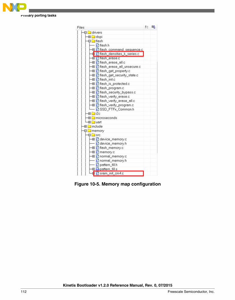
Figure 10-5. Memory map configuration
Primary porting tasks
Kinetis Bootloader v1.2.0 Reference Manual, Rev. 0, 07/2015
112 Freescale Semiconductor, Inc.

Chapter 11Creating a custom flash-resident bootloader
11.1 Introduction
In some situations the ROM-based or full-featured flash-resident bootloader cannot meetthe requirements of a use application. Examples of such situations include specialsignaling requirements on IO, peripherals not supported by the bootloader, or the morebasic need to have as small of a code footprint as possible (for the flash-residentbootloader). This section discusses how to customize the flash-resident bootloader for aspecific use case. The IAR tool chain is used for this example. Other supported toolchains can be similarly configured.
11.2 Where to start
The Kinetis bootloader package comes with various preconfigured projects, includingconfigurations for a flashloader (if applicable for the device) and a flash-residentbootloader. These projects enable all supported features by default, but can easily bemodified to suit the needs of a custom application.
The IAR workspace containing these preconfigured options is located in the<install_dir>/targets/<mcu> folder, where <install_dir> is the folder name of the Kinetisbootloader package once extracted (typically FSL_Kinetis_Bootloader_<version>) and<mcu> is the family of the MCU target. Inside of this folder there is a bootloader.eww file,which is the IAR workspace. The example shows the projects available in the workspacefor the K22F512 MCU family. There are configurations for both Tower System andFreescale Freedom platforms, assuming the boards exist for the specific MCU family.
Kinetis Bootloader v1.2.0 Reference Manual, Rev. 0, 07/2015
Freescale Semiconductor, Inc. 113

Figure 11-1. Projects available in workspace
Each of the projects in the workspace is configured to support all features of thebootloader. This means every peripheral interface that the MCU supports is enabled. Thismakes the bootloader very rich in features, but it also has the largest code footprint,which can be considerable on MCUs with smaller flash configurations.
11.3 Flash-resident bootloader source tree
It is important to understand the source tree to understand where modifications arepossible. Here is an example of a source tree for one of the bootloader configurations.
Flash-resident bootloader source tree
Kinetis Bootloader v1.2.0 Reference Manual, Rev. 0, 07/2015
114 Freescale Semiconductor, Inc.

Figure 11-2. Source tree for bootloader configuration
There are two folders in each bootloader project: a MCU-specific folder and a “src”folder. All files in the MCU-specific folder are located in the <install_dir>/targets/<mcu>/src folder, and are very specific to the target MCU. The “src” folder is located at thetop level of the bootloader tree, and the subfolders in the project correspond to the realfolder/file structure on the PC. The files in the “src” folder are the core files of thebootloader, and include everything from peripheral drivers to individual commands.
Chapter 11 Creating a custom flash-resident bootloader
Kinetis Bootloader v1.2.0 Reference Manual, Rev. 0, 07/2015
Freescale Semiconductor, Inc. 115
The bootloader source is separated in a way that creates a clear line between what a userneeds to modify and what they do not. Among other things, the files in the MCU-specificfolder allow the application to select which peripherals are active as well as how toconfigure the clock, and are intended to be modified by the user. The files in the “src”folder can be modified, but should only require modification where very specificcustomization is needed in the bootloader.
11.4 Modifying source files
The files that cover the majority of the customization options needed by applications arelocated in the MCU-specific folder. These files allow modification to the basicconfiguration elements of the bootloader application, and are not associated with the corefunctionality of the bootloader.
In the MCU-specific folder, the source files contain this information:
• bootloader_config.h – Bootloader configuration options such as encryption,timeouts, CRC checking, the UART module number and baud rate, and mostimportantly, the vector table offset for the user application.
• clock_config_<mcu>.c – Configures the clock for the MCU. This includes system,bus, etc.
• hardware_init_<mcu>.c – Enables and configures peripherals used by theapplication. This includes pin muxing, peripheral initialization, and the pin used as abootloader re-entry (bootstrap) mechanism.
• memory_map_<mcu>.c – Contains a table that stores the memory map informationfor the targeted MCU.
• peripherals_<mcu>.c – Contains the table used by the bootloader to check whichperipheral interfaces are enabled. This is the file used to disable any unwanted orunused peripheral interfaces.
11.5 Example
One of the most common customizations performed on the Kinetis bootloader isremoving unused or unwanted peripheral interfaces. The default configuration of thebootloader enables multiple interfaces, including UART, SPI, I2C and (on some devices)USB and CAN. This example will describe how to modify the provided bootloaderprojects remove the SPI0 interface. The same methodology can be used to select any ofthe supported interfaces.
Modifying source files
Kinetis Bootloader v1.2.0 Reference Manual, Rev. 0, 07/2015
116 Freescale Semiconductor, Inc.

11.6 Modifying a peripheral configuration macro
The bootloader _confg.h file is located in <install_dir>/targets/<mcu>/src. It containsmacros such as:
#if !defined(BL_CONFIG_SPI0)
#define BL_CONFIG_SPI0 (1)
#endif
To remove an interface, either modify this file to set the macro to (0), or pass the macrodefine to the toolchain compiler in the project settings. For example:
BL_CONFIG_SPI0=0
Setting this macro to zero removes the interface from the g_peripherals table andprevents related code from linking into the bootloader image.
Chapter 11 Creating a custom flash-resident bootloader
Kinetis Bootloader v1.2.0 Reference Manual, Rev. 0, 07/2015
Freescale Semiconductor, Inc. 117

Chapter 12Appendix A: status and error codes
Status and error codes are grouped by component. Each component that defines errorshas a group number. This expression is used to construct a status code value.
status_code = -((group * 100) + code)
Component group numbers are listed in this table.
Table 12-1. Component group numbers
Group Component
0 Generic errors
1 Flash driver
2 I2C driver
3 SPI driver
100 Bootloader
101 SB loader
102 Memory interface
103 Property store
The following table lists all of the error and status codes.
Table 12-2. Error and status codes
Name Value Description
kStatus_Success 0 Operation succeeded without error.
kStatus_Fail 1 Operation failed with a generic error.
kStatus_ReadOnly 2 Property cannot be changed because itis read-only.
kStatus_OutOfRange 3 Requested value is out of range.
kStatus_InvalidArgument 4 The requested command's argument isundefined.
kStatus_Timeout 5 A timeout occurred.
kStatus_FlashSizeError 100 Not used.
Table continues on the next page...
Kinetis Bootloader v1.2.0 Reference Manual, Rev. 0, 07/2015
Freescale Semiconductor, Inc. 119

Table 12-2. Error and status codes (continued)
Name Value Description
kStatus_FlashAlignmentError 101 Address or length does not meetrequired alignment.
kStatus_FlashAddressError 102 Address or length is outside addressablememory.
kStatus_FlashAccessError 103 The FTFA_FSTAT[ACCERR] bit is set.
kStatus_FlashProtectionViolation 104 The FTFA_FSTAT[FPVIOL] bit is set.
kStatus_FlashCommandFailure 105 The FTFA_FSTAT[MGSTAT0] bit is set.
kStatus_FlashUnknownProperty 106 Unknown Flash property.
kStatus_I2C_SlaveTxUnderrun 200 I2C Slave TX Underrun error.
kStatus_I2C_SlaveRxOverrun 201 I2C Slave RX Overrun error.
kStatus_I2C_AribtrationLost 202 I2C Arbitration Lost error.
kStatus_SPI_SlaveTxUnderrun 300 SPI Slave TX Underrun error.
kStatus_SPI_SlaveRxOverrun 301 SPI Slave RX Overrun error.
kStatus_UnknownCommand 10000 The requested command value isundefined.
kStatus_SecurityViolation 10001 Command is disallowed because flashsecurity is enabled.
kStatus_AbortDataPhase 10002 Abort the data phase early.
kStatus_Ping 10003 Internal: Received ping during commandphase.
kStatusMemoryRangeInvalid 10200 Memory range conflicts with a protectedregion.
kStatus_UnknownProperty 10300 The requested property value isundefined.
kStatus_ReadOnlyProperty 10301 The requested property value cannot bewritten.
kStatus_InvalidPropertyValue 10302 The specified property value is invalid.
Kinetis Bootloader v1.2.0 Reference Manual, Rev. 0, 07/2015
120 Freescale Semiconductor, Inc.

Chapter 13Appendix B: GetProperty and SetPropertycommands
Properties are the defined units of data that can be accessed with the GetProperty orSetProperty commands. Properties may be read-only or read-write. All read-writeproperties are 32-bit integers, so they can easily be carried in a command parameter. Notall properties are available on all platforms. If a property is not available, GetPropertyand SetProperty return kStatus_UnknownProperty.
The tag values shown in the table below are used with the GetProperty and SetPropertycommands to query information about the bootloader.
Table 13-1. Tag values GetProperty and SetProperty
Name Writable Tag value Size Description
CurrentVersion no 0x01 4 The current bootloaderversion.
AvailablePeripherals no 0x02 4 The set of peripheralssupported on this chip.
FlashStartAddress no 0x03 4 Start address ofprogram flash.
FlashSizeInBytes no 0x04 4 Size in bytes ofprogram flash.
FlashSectorSize no 0x05 4 The size in bytes ofone sector of programflash. This is theminimum erase size.
FlashBlockCount no 0x06 4 Number of blocks inthe flash array.
AvailableCommands no 0x07 4 The set of commandssupported by thebootloader.
CRCCheckStatus no 0x08 4 The status of theapplication CRC check.
Reserved n/a 0x09 n/a
Table continues on the next page...
Kinetis Bootloader v1.2.0 Reference Manual, Rev. 0, 07/2015
Freescale Semiconductor, Inc. 121

Table 13-1. Tag values GetProperty and SetProperty (continued)
Name Writable Tag value Size Description
VerifyWrites yes 0x0a 4 Controls whether thebootloader verifieswrites to flash. TheVerifyWrites feature isenabled by default.
0 - No verification isdone
1 - Enable verification
MaxPacketSize no 0x0b 4 Maximum supportedpacket size for thecurrently activeperipheral interface.
ReservedRegions no 0x0c n List of memory regionsreserved by thebootloader. Returnedas value pairs (<start-address-of-region>,<end-address-of-region>).
• If HasDataPhaseflag is not set,then theResponse packetparameter countindicates numberof pairs.
• If HasDataPhaseflag is set, thenthe secondparameter is thenumber of bytesin the dataphase.
RAMStartAddress no 0x0e 4 Start address of RAM.
RAMSizeInBytes no 0x0f 4 Size in bytes of RAM.
SystemDeviceId no 0x10 4 Value of the KinetisSystem DeviceIdentification register.
FlashSecurityState no 0x11 4 Indicates whetherFlash security isenabled.
0 - Flash security isdisabled
1 - Flash security isenabled
UniqueDeviceId no 0x12 n Unique deviceidentification, value ofKinetis UniqueIdentification registers
Table continues on the next page...
Kinetis Bootloader v1.2.0 Reference Manual, Rev. 0, 07/2015
122 Freescale Semiconductor, Inc.

Table 13-1. Tag values GetProperty and SetProperty (continued)
Name Writable Tag value Size Description
(16 for K seriesdevices, 12 for KLseries devices)
FlashFacSupport no 0x13 4 FAC (Flash AccessControl) support flag
0 - FAC not supported
1 - FAC supported
FlashAccessSegmentSize
no 0x14 4 The size in bytes of 1segment of flash.
FlashAccessSegmentCount
no 0x15 4 FAC segment count(The count of flashaccess segmentswithin the flash model.)
FlashReadMargin yes 0x16 4 The margin levelsetting for flash eraseand program verifycommands.
0=Normal
1=User
2=Factory
QspiInitStatus no 0x17 4 The result of the QSPIor OTFAD initializationprocess.
405 - QSPI is notinitialized
0 - QSPI is initialized
TargetVersion no 0x18 4 Target build versionnumber.
ExternalMemoryAttributes
no 0x19 24 List of attributessupported by thespecified memory Id(0=Internal Flash,1=QuadSpi0). Seedescription for thereturn value in thesectionExternalMemoryAttributes Property.
Chapter 13 Appendix B: GetProperty and SetProperty commands
Kinetis Bootloader v1.2.0 Reference Manual, Rev. 0, 07/2015
Freescale Semiconductor, Inc. 123

Chapter 14Revision history
14.1 Revision HistoryThis table shows the revision history of the document.
Table 14-1. Revision history
Revision number Date Substantive changes
0 07/2015 Kinetis Bootloader 1.2.0 initial release
Kinetis Bootloader v1.2.0 Reference Manual, Rev. 0, 07/2015
Freescale Semiconductor, Inc. 125

Document Number: KBTLDR120RMRev. 007/2015
Information in this document is provided solely to enable system and software
implementers to use Freescale products. There are no express or implied copyright
licenses granted hereunder to design or fabricate any integrated circuits based on the
information in this document.
Freescale reserves the right to make changes without further notice to any products
herein. Freescale makes no warranty, representation, or guarantee regarding the
suitability of its products for any particular purpose, nor does Freescale assume any
liability arising out of the application or use of any product or circuit, and specifically
disclaims any and all liability, including without limitation consequential or incidental
damages. “Typical” parameters that may be provided in Freescale data sheets and/or
specifications can and do vary in different applications, and actual performance may
vary over time. All operating parameters, including “typicals,” must be validated for
each customer application by customer’s technical experts. Freescale does not convey
any license under its patent rights nor the rights of others. Freescale sells products
pursuant to standard terms and conditions of sale, which can be found at the following
address: freescale.com/SalesTermsandConditions.
How to Reach Us:Home Page: freescale.com
Web Support: freescale.com/support
Freescale, the Freescale logo, and Kinetis are trademarks of Freescale
Semiconductor, Inc., Reg. U.S. Pat. & Tm. Off. Tower is a trademark of Freescale
Semiconductor. All other product or service names are the property of their respective
owners. ARM, ARM Powered Logo, and Cortex are registered trademarks of ARM
limited (or its subsidiaries) in the EU and/or elsewhere. All rights reserved.
© 2015 Freescale Semiconductor, Inc.