Embed Size (px)
Citation preview

Kinetis M Family Single-PhaseEnergy Meter Design Reference
Manual
Document Number: DRM142Rev 0, 06/2014

Kinetis M Family Single-Phase Energy Meter Design Reference Manual, Rev. 0, 06/2014
2 Freescale Semiconductor, Inc.

Contents
Section number Title Page
Chapter 1Introduction
1.1 Overview.........................................................................................................................................................................7
1.2 Application features........................................................................................................................................................ 7
1.3 KM devices advantages.................................................................................................................................................. 8
Chapter 2Metering Theory and Configurations
2.1 Energy meter...................................................................................................................................................................11
2.2 Common terms used in metering.................................................................................................................................... 12
2.3 Metering calculations......................................................................................................................................................14
2.3.1 Wiring system.................................................................................................................................................... 16
Chapter 3Hardware Design
3.1 Block diagram.................................................................................................................................................................19
3.2 Power supply...................................................................................................................................................................19
3.2.1 Main power supply.............................................................................................................................................20
3.2.2 Auxiliary battery................................................................................................................................................ 21
3.2.3 Neutral missing CT............................................................................................................................................ 22
3.3 Display interface............................................................................................................................................................. 22
3.3.1 Liquid Crystal Display (LCD) interface............................................................................................................ 22
3.3.2 LCD backlight....................................................................................................................................................23
3.4 LED interface..................................................................................................................................................................24
3.5 Keyboard (User) interface...............................................................................................................................................24
3.6 Analog signal conditioning.............................................................................................................................................24
3.6.1 Current signal conditioning circuit.................................................................................................................... 25
3.6.2 Voltage signal conditioning circuit.................................................................................................................... 25
3.7 Cover open tamper detection.......................................................................................................................................... 26
3.8 Optical communication port........................................................................................................................................... 26
Kinetis M Family Single-Phase Energy Meter Design Reference Manual, Rev. 0, 06/2014
Freescale Semiconductor, Inc. 3

Section number Title Page
3.9 Serial Wire Debug (SWD) module ................................................................................................................................ 28
3.10 Microcontroller requirements......................................................................................................................................... 29
3.10.1 Crystal requirements.......................................................................................................................................... 29
3.10.2 LCD requirements..............................................................................................................................................30
3.11 Assembled printed circuit board..................................................................................................................................... 30
Chapter 4Software Design
4.1 Introduction.....................................................................................................................................................................33
4.2 Hardware resource allocation......................................................................................................................................... 33
4.3 Interrupt priority..............................................................................................................................................................34
4.4 Measurement...................................................................................................................................................................34
4.4.1 Modes.................................................................................................................................................................34
4.4.2 Meter startup sequence.......................................................................................................................................35
4.4.3 Metering modes..................................................................................................................................................37
4.4.4 Measurement parameters................................................................................................................................... 41
4.4.5 Initialization....................................................................................................................................................... 42
4.4.6 Sampling............................................................................................................................................................ 43
4.4.7 Metering process................................................................................................................................................ 43
4.5 User interface.................................................................................................................................................................. 47
4.5.1 Introduction........................................................................................................................................................47
4.5.2 LCD panel.......................................................................................................................................................... 47
4.6 Communication...............................................................................................................................................................48
4.6.1 Implementation.................................................................................................................................................. 49
4.7 Calibration.......................................................................................................................................................................50
4.7.1 Auto calibration process.....................................................................................................................................50
4.8 Tamper detection............................................................................................................................................................ 52
4.8.1 Box Open tamper............................................................................................................................................... 52
4.8.2 Magnetic tamper................................................................................................................................................ 53
4.8.3 Phase reversal tamper.........................................................................................................................................53
Kinetis M Family Single-Phase Energy Meter Design Reference Manual, Rev. 0, 06/2014
4 Freescale Semiconductor, Inc.

Section number Title Page
4.8.4 Partial Earth tamper........................................................................................................................................... 53
4.8.5 Neutral Missing tamper......................................................................................................................................53
4.9 Database..........................................................................................................................................................................54
4.9.1 Introduction........................................................................................................................................................54
4.9.2 Assumptions, constraints, and limitations .........................................................................................................54
4.9.2.1 DB Application Block..........................................................................................................................55
4.9.3 Implementation.................................................................................................................................................. 56
4.9.4 Memory map...................................................................................................................................................... 56
4.9.5 State Machines / Control Charts........................................................................................................................ 57
4.9.6 Maximum demand............................................................................................................................................. 59
4.9.7 Load profile........................................................................................................................................................59
Chapter 5Revision history
5.1 Revision history.............................................................................................................................................................. 63
Kinetis M Family Single-Phase Energy Meter Design Reference Manual, Rev. 0, 06/2014
Freescale Semiconductor, Inc. 5

Kinetis M Family Single-Phase Energy Meter Design Reference Manual, Rev. 0, 06/2014
6 Freescale Semiconductor, Inc.

Chapter 1Introduction
1.1 OverviewThis document describes the design of a single-phase energy meter reference design,based on Freescale KM family microcontroller specifically targeted for single-phasemetering applications. This design is targeted for basic and smart meters. This design is areference for designing energy meter or electricity meter, which measures and displaysactive energy (kWh), reactive energy (kVArh), apparent energy (kVAh), voltage, current,frequency, power factor, active power (kW), reactive power (kVAr), apparent power(kVA), and maximum demand in kW. The LCD panel displays current date and time.
1.2 Application featuresThe features of KM family reference design are as follows:
• Mode:• Single-phase (1Ф-2W)
• Measurement and LCD display of:• RMS
• Voltage• Phase current• Neutral current
• Total• Active power• Reactive power• Apparent power
• Frequency• Tamper count• Power factor• Energy
Kinetis M Family Single-Phase Energy Meter Design Reference Manual, Rev. 0, 06/2014
Freescale Semiconductor, Inc. 7

• Active• Reactive• Apparent
• Date• Time• Maximum demand
• Operating frequency range 45–65 Hz• Tamper information• Optical port interface (IEC62056–21)• Serial port for calibration and diagnostics• Navigation using key• Selectable display list in auto scroll and push button modes• Expansion port for AMR via SCI
The following items are provided to the user to develop energy meter:• Reference energy meter.• Software – design document, and source code.• Hardware documentation – detailed design document (excel format), BOM,
Schematics, wiring diagram, and EMI/EMC test reports of reference energy meter.
1.3 KM devices advantagesThe advantages of using KM devices are as follows:
• Core frequency can go up to 50 MHz, thus capable of enough horsepower forcomputation intensive applications.
• 24-Bit Sigma-Delta Analog Front End (AFE) with four independent channels; twowith independent PGA.
• Built-in stable voltage reference.• Selectable voltage reference - Internal or External.• External gain switching is not required.• Signal conditioning is not required.• Phase error compensation using delay registers in AFE.• PLL for stable clock generation for AFE and other peripherals.• Watchdog runs on independent RC oscillator which is separate from core clock.• Capable of running from a single clock source (external 32 kHz crystal).• Ultra low-power independent RTC with calendar features and three tamper pins.• RTC runs in independent power domain (always on battery); thus no switch and
hence no possibility of any glitch.• AMR SCI or SPI can communicate with 5 V AMR interfaces.
KM devices advantages
Kinetis M Family Single-Phase Energy Meter Design Reference Manual, Rev. 0, 06/2014
8 Freescale Semiconductor, Inc.
• Peripheral crossbar that can help in connecting a peripheral to any peripheralincluding inputs and outputs; helps in layout and other functionalities.
• 4-Channel DMA for data transfers without core intervention.• Integrated 16-bit SAR Analog-to-Digital Converter.• Single cycle 32x32 Multiply.• Built-in LCD controller.
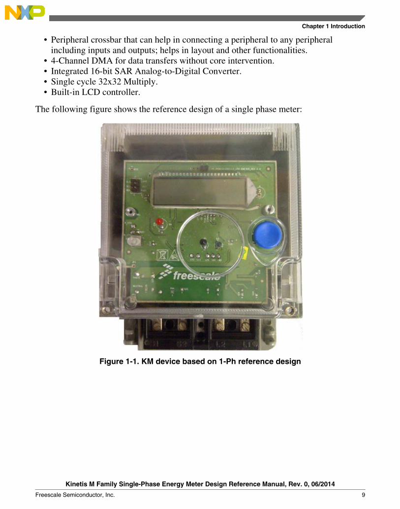
The following figure shows the reference design of a single phase meter:
Figure 1-1. KM device based on 1-Ph reference design
Chapter 1 Introduction
Kinetis M Family Single-Phase Energy Meter Design Reference Manual, Rev. 0, 06/2014
Freescale Semiconductor, Inc. 9

KM devices advantages
Kinetis M Family Single-Phase Energy Meter Design Reference Manual, Rev. 0, 06/2014
10 Freescale Semiconductor, Inc.

Chapter 2Metering Theory and Configurations
2.1 Energy meterCurrent is sensed using current transformer or shunt resistor or hall sensors. Voltage issensed using potential divider circuit or voltage transformer. Sensed voltage and currentsignals are multiplied and integrated over period of time to obtain energy and it is storedin a register.
The following figure shows the concept of block diagram of Energy Meter:
Current sensing
Voltage sensing
RegisterIntegratorMultiplier
t
Figure 2-1. Block diagram of basic energy meter
• An Electricity Meter or Energy Meter is a device that measures the amount ofelectrical energy supplied to a residence, business, or machine.
• The unit for measurement of active electrical energy is kilowatt hour (kWh), which isequal to the amount of energy used by load of one kilowatt over a period of one hour.
• Demand is normally measured in watts or VA, but averaged over a period, mostoften a quarter or half hour.
• Reactive power is measured in "Volt-amperes reactive", (VArh) in kilovar-hours. Alagging or inductive load have negative reactive power, such as an induction motor.A leading or capacitive load have positive reactive power.
• Volt-amperes measures all power passed through a distribution network, includingreactive and actual. This is equal to the product of root-mean-square volts andamperes.
• Distortion of the electric current by loads is measured in several ways:
Kinetis M Family Single-Phase Energy Meter Design Reference Manual, Rev. 0, 06/2014
Freescale Semiconductor, Inc. 11

• Power factor—It is the ratio of resistive (or real power) to volt-amperes(apparent power). A capacitive load has a leading power factor, and an inductiveload has a lagging power factor. A purely resistive load exhibits a power factorof 1.
• Current harmonics—This is a measure of distortion of the current waveform.Odd harmonics are not permissible to exceed specific limits because it mayinterfere with the operation of other equipment.
2.2 Common terms used in meteringBurden: The load, usually expressed in volt-amperes at a specified power factor, placedon instrument transformer secondary by the associated meter coils, leads, and otherconnected devices.
Capacitive reactance: Impedance due to capacitance. This is expressed in ohms. Thecapacitive reactance varies indirectly with frequency.
Circuit, three-wire: It is a metallic circuit formed by three conductors insulated fromeach other.
Circuit, two-wire:It is a metallic circuit formed by two adjacent conductors insulatedfrom each other. When serving domestic loads one of these wires is usually grounded.
Constant, watt-hour: The number of watt-hours represented by one increment (pulseperiod) of serial data. Example: Kh or Kt = 1.25 watt-hours/pulse.
Current transformer: Current transformer (CT) is used for measurement of electriccurrents.
Current transformer phase angle: The angle between the current leaving the identifiedsecondary terminal and the current entering the identified primary terminal. This angle isconsidered positive when the secondary current leads the primary current. Or The anglebetween the primary current vector and the secondary current vector reversed; it isconveniently considered as positive when the reversed secondary current vector leads theprimary current vector.
Cycle: One complete set of positive and negative values of an alternating current orvoltage. These values repeat themselves at regular intervals.
Demand: The average value of power or related quantity over a specified interval oftime. Demand is expressed in kilowatts, kilovolt amperes, kiloVARs, or other suitableunits. Its interval could be like 1, 5, 10, 15, 30, or 60 minutes.
Common terms used in metering
Kinetis M Family Single-Phase Energy Meter Design Reference Manual, Rev. 0, 06/2014
12 Freescale Semiconductor, Inc.

Demand, maximum: The highest demand measured over a selected period of time suchas 30 minutes. It is also termed as Peak Demand.
Effective value (root-mean-square value): The effective value of a periodic quantity isthe square root of the average of the squares of the instantaneous value of the quantitytaken throughout one period. This value is also called the root-mean-square value and isthe value normally reported by alternating current instruments.
Electrical degree: The 360th part of one complete alternating current cycle.
Electricity meter: A device that measures and records the summation of an electricalquantity over a period of time.
Frequency: Frequency is the number of occurrences of a repeating event per unit time.Period is the duration of one cycle in a repeating event, so the period is reciprocal offrequency. The unit of frequency is hertz (Hz). One hertz is equal to one cycle persecond.
Lagging current: An alternating current which, in each half-cycle, reaches its maximumvalue a fraction of a cycle later than the maximum value of the voltage which produces it.
Leading current: An alternating current which, in each half-cycle, reaches its maximumvalues a fraction of a cycle sooner than the maximum value of the voltage whichproduces it.
Meter constant: The number of times the “Calib LED” blinks to record 1 kWh or 1 unitof energy. For example, if the meter constant is 3200, it means that 3200 impulses of thecalib LED will result in the unit register incrementing by 1.
Optical port: A communication interface on metering products, which allows thetransfer of information while providing electrical isolation and metering security. Thecommunication medium typically used is infrared light transmitted and received throughthe meter cover.
Phantom load: A device which supplies various load current for meter testing, used inportable form for field testing. The power source is usually the service voltage which istransformed to a low value. The load currents are obtained by suitable resistors switchedin series with the isolated low secondary voltage and output terminals. The sameprinciple is used in most meter test boards.
Phase angle: The phase angle or phase difference between a sinusoidal voltage and asinusoidal current is defined as the number of electrical degrees between the beginning ofthe cycle of voltage and the beginning of the cycle of current.
Chapter 2 Metering Theory and Configurations
Kinetis M Family Single-Phase Energy Meter Design Reference Manual, Rev. 0, 06/2014
Freescale Semiconductor, Inc. 13

Active power: The time average of the instantaneous power over one period of the wave.For sinusoidal quantities in a two-wire circuit, it is the product of voltage, current, andcosine of the phase angle between them. For non-sinusoidal quantities, it is the sum of allthe harmonic components, each determined as above. In a poly-phase circuit it is the sumof the active powers of the individual phases.
Apparent power: The product of the root-mean-square current and root-mean-squarevoltage for any waveform. For sinusoidal quantities, apparent power is the square root ofthe sum of the squares of active and reactive powers.
Reactive power: For sinusoidal quantities in a two-wire circuit, reactive power is theproduct of voltage, current, and sine of the phase angle between them with the currenttaken as reference.
With non-sinusoidal quantities, it is the sum of all the harmonic components, eachdetermined as above. In a poly-phase circuit, it is the sum of the reactive powers of theindividual phases.
Power factor: The ratio of the active power to the apparent power.
Reference meter: A meter used to measure the unit of electric energy. It is usuallydesigned and operated to obtain the highest accuracy and stability in a controlledlaboratory environment.
Watt: The practical unit of active power which is defined as the rate at which energy isdelivered to a circuit. It is the power expended when a current of one ampere flowsthrough a resistance of one ohm.
Watt-hour: The practical unit of electric energy which is expended in 1 hour when theaverage power during the hour is 1 watt.
2.3 Metering calculationsThe formulas used for calculating various electrical parameters in Freescale referenceenergy meter are explained in subsequent subsections. These formulae are for referenceonly and the results obtained from these formulae may be averaged over the period oftime to obtain stabilized readings.
Equation 1. Line to neutral voltages
Metering calculations
Kinetis M Family Single-Phase Energy Meter Design Reference Manual, Rev. 0, 06/2014
14 Freescale Semiconductor, Inc.

Equation 2. Phase and average current
Where,• n = number of samples per cycles• VAN = Line to neutral RMS voltages for A phase. VAn is the instantaneous nth
sample (1 to 60) of A Phase Voltage.
Equation 3. Active and net active power
Where,• n = number of samples per cycles• IA = Line Currents for A Phase.• IN = Neutral current. IAn is the instantaneous sample (1 to 60) of A Phase Current
Equation 4. Reactive and net reactive power
Equation 5. Apparent and net apparent power
Equation 6. Power factor
Equation 7. Frequency
Equation 8. Energy calculation
Chapter 2 Metering Theory and Configurations
Kinetis M Family Single-Phase Energy Meter Design Reference Manual, Rev. 0, 06/2014
Freescale Semiconductor, Inc. 15
NOTEAll the calculations discussed in this section are in terms ofADC counts. The calculated results will be further computedusing calibration constants.
RMS apparent power is computed from product of Vrms and Irms. Angle compensation oftotal power is calculated as follows:
Power Factor = Total Active Power / RMS Apparent Power
Angle = acos (Power Factor)
An error in angle measurement is derived by measuring powers as shown in the belowtable:
Current Actual Power Measured Powerat 60
Error in Angle Measured Powerat 300
Error in Angle
40 4800 4750 -0.343986459 4865 0.448974936
25 3000 2962 -0.418132799 3039.5 0.436514072
10 1200 1187.5 -0.343986459 1212 0.331352363
5 600 595 -0.275283697 605.3 0.292637051
1 120 119.2 -0.220287608 120.77 0.212489601
0.25 30 29.8 -0.220287608 30.15 0.165536962
It is difficult to identifying whether the voltage is leading or lagging. This is identified bychecking the sign of current sample immediately after voltage's zero crossover. The signof current at that instance tells lag/lead. Then, the derived current angle derived above isrotated by “Error in Angle” amount to bring it to normal.
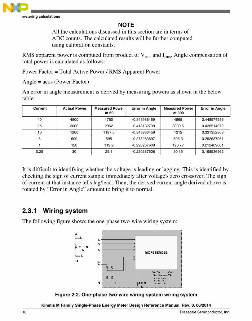
2.3.1 Wiring system
The following figure shows the one-phase two-wire wiring system:
Figure 2-2. One-phase two-wire wiring system wiring system
Metering calculations
Kinetis M Family Single-Phase Energy Meter Design Reference Manual, Rev. 0, 06/2014
16 Freescale Semiconductor, Inc.

The following figure shows the Lag and Lead concept of an energy meter
Figure 2-3. Phasor diagram of an energy meter
Where,• Φ = (phase angle between voltage and current) = ΦV – ΦI• ΦV = phase angle of voltage signal• ΦI = phase angle of current signal
From the Trigonometric functions, Cosine (cos) components are positive in first andfourth quadrant and negative in second and third quadrant. Similarly, Sine (sin)components are positive in first and second quadrant and negative in third and fourthquadrant. Power (kW) and Power factor (PF) are cosine components and Reactive Power(kVAr) is sine component.
Current lags by an angle Φ with respect to Voltage is called lagging power factor and thesign of the angle within voltage and current will be positive. Typical example for thisload is Inductive load, that is, Induction motor.
Current leads by an angle Φ with respect to Voltage is called leading power factor andand the sign of the angle within voltage and current will be negative. Typical example forthis load is capacitive load, that is, Synchronous motor.
A quantity which includes magnitude, direction, and time relationship is known asPhasor. The Phasors are used to represent sinusoidal voltages and currents by plotting onrectangular coordinates.
Chapter 2 Metering Theory and Configurations
Kinetis M Family Single-Phase Energy Meter Design Reference Manual, Rev. 0, 06/2014
Freescale Semiconductor, Inc. 17

Metering calculations
Kinetis M Family Single-Phase Energy Meter Design Reference Manual, Rev. 0, 06/2014
18 Freescale Semiconductor, Inc.

Chapter 3Hardware Design
3.1 Block diagramThe following block diagram gives the overview of single-phase reference energy meterbased on KM family devices.
Figure 3-1. Hardware block diagram
3.2 Power supplyThe reference design runs on one of the following three power sources:
1. Main power supply
Kinetis M Family Single-Phase Energy Meter Design Reference Manual, Rev. 0, 06/2014
Freescale Semiconductor, Inc. 19

2. Auxiliary battery3. Neutral missing CT
3.2.1 Main power supply
This is a capacitive power supply rating 4 VA. This power supply can provide up to 11.5ma current at 240 V.
High Pass filterInput AC supplyOne way rectifier and regulator LDO and battery
Non isolated 3.3 V power supply
Capacitor and current limiter
Figure 3-2. Block diagram of main power supply
All the blocks and corresponding schematic of Main Power Supply block diagram areexplained as follows:
Input AC is fed through two pin terminal and varacter U5 protects against surge. Theresistor R30 limits the current in the power supply section which is followed by a high-pass filter formed by the C25 capacitor.
Figure 3-3. Circuit diagram of capacitive power supply
The AC capacitor C21 offers impedance to the current and decides the maximum value ofaverage DC current (Iin) that can be fed to the MCU.
Equation 9. Maximum value of average DC current
Where,• Iin is the average value of DC current
Power supply
Kinetis M Family Single-Phase Energy Meter Design Reference Manual, Rev. 0, 06/2014
20 Freescale Semiconductor, Inc.
• F is the frequency of input supply voltage• 2πFC is the impedance offered (in the schematic C is C21)
The further diodes and transistor network act as one way rectifier and zener diode (D13)acts as voltage regulator. C26 capacitor is the bulk storage capacitor and is charged up to5.6 V. So the voltage rating should be more than 10 V. This capacitor reduces ripplesfrom the output supply. As one tries to withdraw more and more current, the ripples willincrease. The high value of C21 capacitor would reduce the ripples from the supply up toa certain limit; this will increase the rating of power supply. The LDO U4 has an enableinput and provides stable 3.3V output.
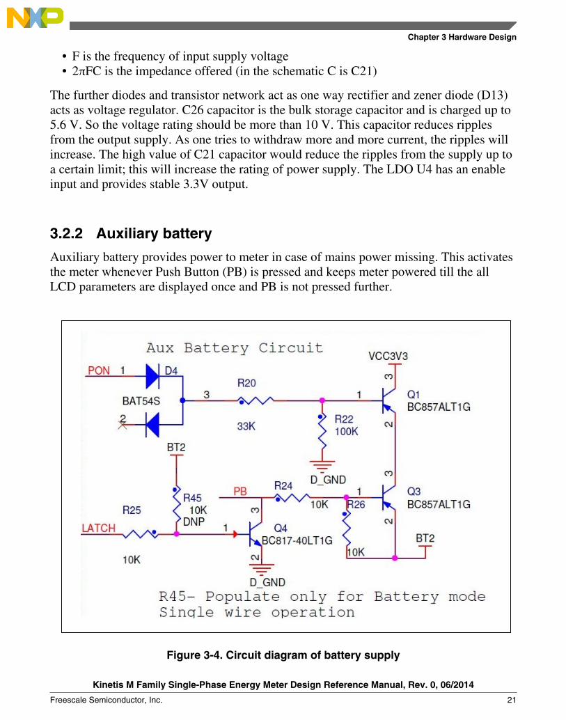
3.2.2 Auxiliary battery
Auxiliary battery provides power to meter in case of mains power missing. This activatesthe meter whenever Push Button (PB) is pressed and keeps meter powered till the allLCD parameters are displayed once and PB is not pressed further.
Figure 3-4. Circuit diagram of battery supply
Chapter 3 Hardware Design
Kinetis M Family Single-Phase Energy Meter Design Reference Manual, Rev. 0, 06/2014
Freescale Semiconductor, Inc. 21

PON signal is generated from the power supply section, so this auxiliary battery willpower up meter only in case main power is absent. Latch signal driven from MCU keepsmeter ON till its battery operated operation is not completed after the PB is pressed.
3.2.3 Neutral missing CT
Neutral missing CT provides the power in case of single-wire metering for tamperdetection. If any of the two wires (Phase or Neutral) is removed from the meter terminaland current is passing through the single connecting wire then meter will get power upusing this CT.
Figure 3-5. Circuit diagram of neutral missing power CT
3.3 Display interface
Display interface
Kinetis M Family Single-Phase Energy Meter Design Reference Manual, Rev. 0, 06/2014
22 Freescale Semiconductor, Inc.

3.3.1 Liquid Crystal Display (LCD) interface
The following figure represents the typical example of LCD displays used in single-phasemetering:
Figure 3-6. LCD display
• Display type: STN/Yellow-Green• Viewing direction: 6 o’clock• Polarizer type: Transflective, positive.
The LCD can display import, export, lead, lag, kW, kVAr, kWh, kVArh, number oftampers, maximum demand, date, time, frequency (Hz) and many more.
LCD has 80 segments and ¼ duty cycle (4 backplanes).
LCD interfaces to the 'built-in LCD driver' of the controller and driver is operating in ¼duty cycle and 1/3 bias (voltage levels) mode.
3.3.2 LCD backlight
The LCD built without an internal back light source which necessitates the use ofexternal sources of light to make the screen and information visible.
The following figure shows the circuit diagram of LCD backlight:
Figure 3-7. Circuit diagram of LCD backlight
Chapter 3 Hardware Design
Kinetis M Family Single-Phase Energy Meter Design Reference Manual, Rev. 0, 06/2014
Freescale Semiconductor, Inc. 23

Backlight illuminates the LCD from back of the display panel which increases readabilityin low light conditions.
3.4 LED interfaceThis is the calibration LED. Active energy accuracy of the meter is verified by pulsemethod. kWh LED pulses are used to measure the accuracy of active energy. As theactive energy starts accumulating kWh LED will blink at the rate of 3200 impulses/kWh.
The following circuit shows how Calib LED is driven from MCU:
Figure 3-8. Circuit diagram calib LED
3.5 Keyboard (User) interfaceThere is one push button on the meter, which is used to scroll the display through displaylist. It powers ON the meter if the main power is OFF.
3.6 Analog signal conditioningA signal conditioning block is used to bring voltage and load currents to the requiredvoltage levels.
LED interface
Kinetis M Family Single-Phase Energy Meter Design Reference Manual, Rev. 0, 06/2014
24 Freescale Semiconductor, Inc.

Figure 3-9. Circuit diagram for signal conditioning
3.6.1 Current signal conditioning circuit
A shunt resistor is present on the phase element and a Current Transformer (CT) on theneutral element. Shunt value is 500 µΩ, which just about saturates at approximately 44 Aif a gain of 8 is used on the PGA. A burden resistor of 10 Ω on the CT secondarysaturates at 44 A. Signal conditioning like level shifting or external gain is not requiredfor the signals.
3.6.2 Voltage signal conditioning circuit
A resistor divider network is used to step down the voltage to measurable level. No othersignal conditioning is required.
Chapter 3 Hardware Design
Kinetis M Family Single-Phase Energy Meter Design Reference Manual, Rev. 0, 06/2014
Freescale Semiconductor, Inc. 25

3.7 Cover open tamper detectionSW2 switch contact position will be open when the enclosure top cover is closed. Thiswould be considered as no tamper condition and BT1 will not be loaded by R31. Whenenclosure top cover is opened, SW2 contacts position will be closed. This is Tampercondition and BT1 will be loaded by R31.
The battery voltage will drop across the resistor R31 and the voltage will appear at thetamper pin. The tamper will be detected by RTC inside meter.
The cover open tamper can be detected even under power OFF condition of the meter.There is provision of power on the meter when SW2 switch is closed. This will connectthe BT2 power back-up battery to system supply. The following figure displays thecircuit diagram of cover open tamper:
Figure 3-10. Circuit diagram of cover open tamper
3.8 Optical communication portThe Meter has one optical communication port as per IEC62056-21. The following figuredisplays the hardware circuit associated with optical port communication:
Cover open tamper detection
Kinetis M Family Single-Phase Energy Meter Design Reference Manual, Rev. 0, 06/2014
26 Freescale Semiconductor, Inc.

Figure 3-11. Circuit diagram of optical port
Optical communication—data exchange for metering reading, tariff, and load control. Itis complied with IEC62056-21 standard. The standard is International Energy Meteringdata exchange Specification.
The following figure displays the position of receiver and transmitter of optical port onthe meter:
Infrared receiver Infrared transmitter
6.5 mm +- 5.5 mm symmetrical
Figure 3-12. Position of receiver and transmitter of optical port on meter
Chapter 3 Hardware Design
Kinetis M Family Single-Phase Energy Meter Design Reference Manual, Rev. 0, 06/2014
Freescale Semiconductor, Inc. 27

In Figure 3-12 the optical head (optical to RS232 converter) is placed over the opticalport interface of the meter and RS232 is connected to PC for communication. The pitchprovided on the tariff device is 6.5 mm. The infrared receiver in the tariff device isaligned directly opposite the infrared transmitter in the reading head and infrared receiverin the reading head is directly opposite the infrared transmitter in the tariff device.
3.9 Serial Wire Debug (SWD) moduleJ-link is a 20-pin header, so an adapter cable is used to connect the 20-pin. J-linkconnector with 6-pin headers on board. Its communication interface is used forprogramming the controller. Reduced 6-pin nonisolated header is available on the meter.So, user must use the isolated power source to power meter, when jlink is connected onmeter.
The following figure shows a IAR J-link debugger which is used to program and debugthe MCU:
Figure 3-13. IAR J-link debugger
Serial Wire Debug (SWD) module
Kinetis M Family Single-Phase Energy Meter Design Reference Manual, Rev. 0, 06/2014
28 Freescale Semiconductor, Inc.
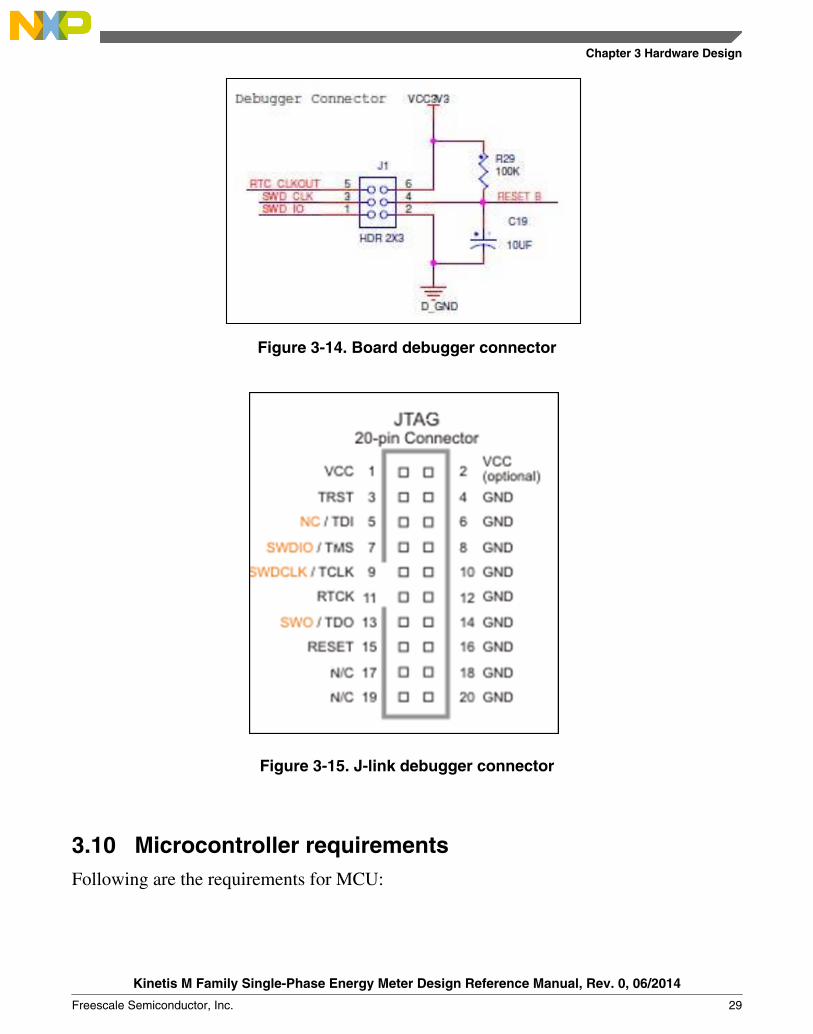
Figure 3-14. Board debugger connector
Figure 3-15. J-link debugger connector
3.10 Microcontroller requirementsFollowing are the requirements for MCU:
Chapter 3 Hardware Design
Kinetis M Family Single-Phase Energy Meter Design Reference Manual, Rev. 0, 06/2014
Freescale Semiconductor, Inc. 29

3.10.1 Crystal requirements
External 32.768 kHz crystal is used for RTC and same clock is multiplied by FLL/ PLLwhich is internal to the controller to provide clock to core, bus and peripherals.
3.10.2 LCD requirements
LCD driver of the controller requires three ceramic capacitors whose typical value is 0.1µF for LCD bias voltages and 0.1 µF for LCD charge pump.
3.11 Assembled printed circuit boardFigure 3-16 shows the top view of the assembled board:
Assembled printed circuit board
Kinetis M Family Single-Phase Energy Meter Design Reference Manual, Rev. 0, 06/2014
30 Freescale Semiconductor, Inc.
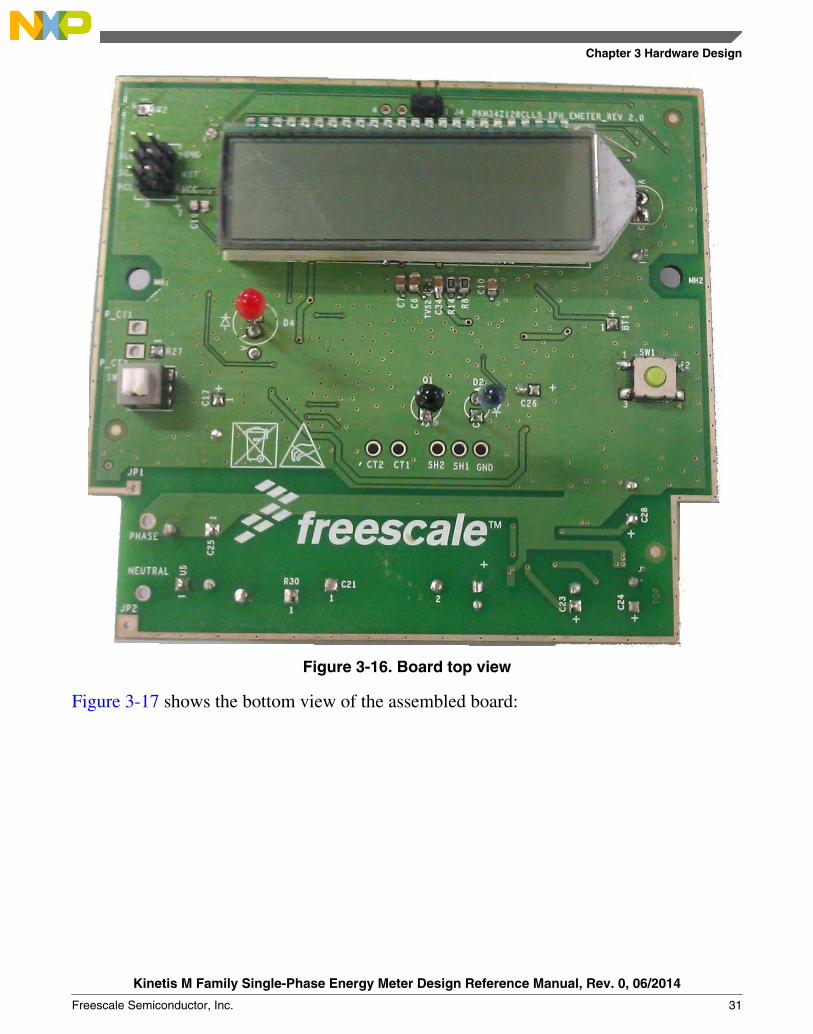
Figure 3-16. Board top view
Figure 3-17 shows the bottom view of the assembled board:
Chapter 3 Hardware Design
Kinetis M Family Single-Phase Energy Meter Design Reference Manual, Rev. 0, 06/2014
Freescale Semiconductor, Inc. 31
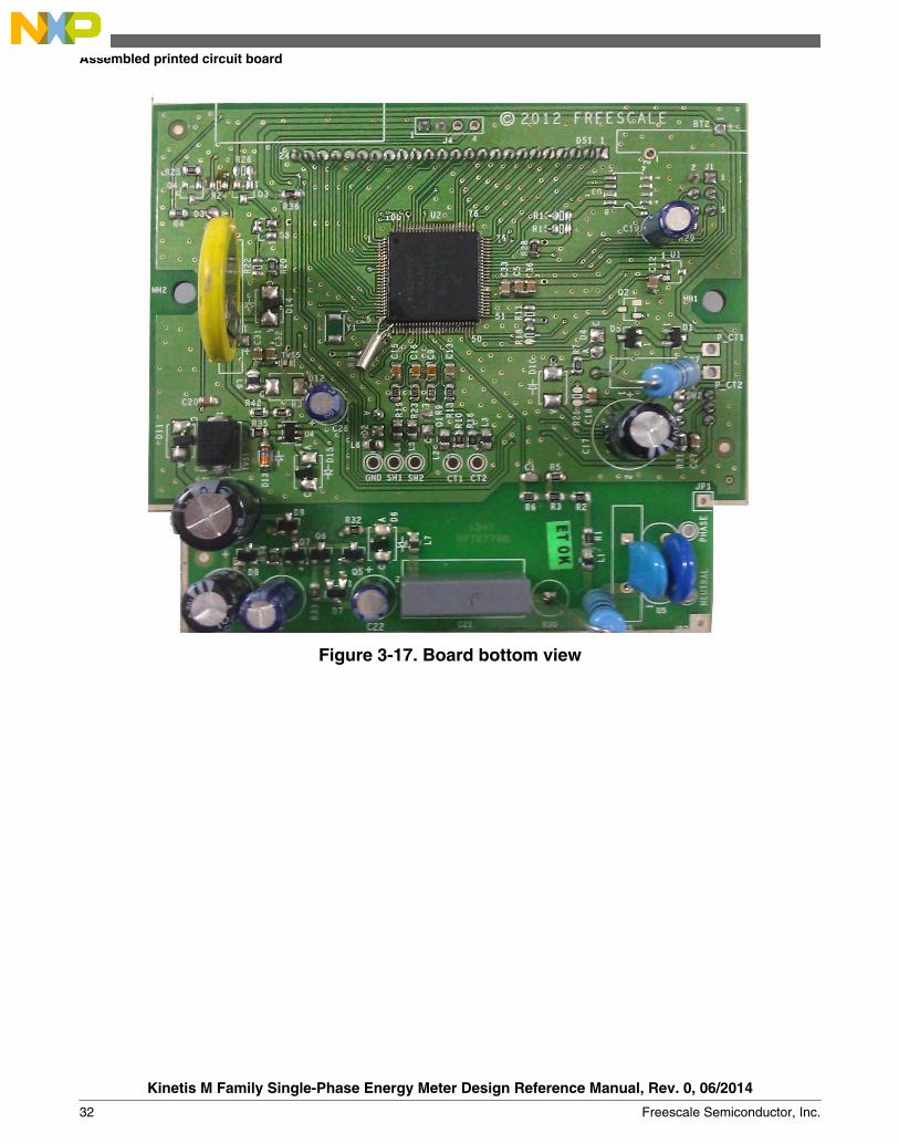
Figure 3-17. Board bottom view
Assembled printed circuit board
Kinetis M Family Single-Phase Energy Meter Design Reference Manual, Rev. 0, 06/2014
32 Freescale Semiconductor, Inc.

Chapter 4Software Design
4.1 IntroductionThis section describes the software design of Single-Phase Energy Meter application.Software design mainly consists of measurement, database, user interface, andcommunication modules. The objective of this chapter is to understand the softwaredesign. The software architecture is custom kernel running on KM device controller. Thecontroller uses the external RTC clock source and PLL to generate the system clock of12.28 MHz.
The software has following main modules:
• Measurement Module• Database Management Module• User Interface Module• Communication Module
4.2 Hardware resource allocationThe following table lists the MCU resources used in metering application.
Table 4-1. Hardware resource allocation
Peripherals Usage
TMR1 General purpose timeout timer
TMR2 Zero crossing timing to compute frequency
AFE0 Phase Current
AFE1 Neutral Current
AFE2 Voltage
I2C1 EEPROM
SCI1 Optical communication
Table continues on the next page...
Kinetis M Family Single-Phase Energy Meter Design Reference Manual, Rev. 0, 06/2014
Freescale Semiconductor, Inc. 33

Table 4-1. Hardware resource allocation (continued)
Peripherals Usage
XBAR Connect CMP1 to TMR2
CMP1 Zero cross detection to detect voltage and compute frequency
LCD Display
VREF Voltage reference for AFE
RTC Real time management and cover open tamper
NVIC Interrupt controller for various interrupts
PLL Bus and AFE clock source
4.3 Interrupt priorityThe following table shows interrupts priorities of various modules that are set in thesoftware. The lowest number denotes the highest priority.
Table 4-2. Interrupt priorities
Interrupts Priority level
TMR1 2
TMR2 2
AFE0 3
AFE1 3
AFE2 3
I2C1 0
SCI1 2
RTC 3
DMA 2
Push button 3
4.4 MeasurementMetering application software operates MCUs in different configuration depending onthe input conditions. The following sections describe the requirement of the differentmodes, what are the different modes, and how they have been implemented.
Interrupt priority
Kinetis M Family Single-Phase Energy Meter Design Reference Manual, Rev. 0, 06/2014
34 Freescale Semiconductor, Inc.

4.4.1 Modes
The modes are required because the meter should power up at 90 V upwards and shouldbe fully functional at 120 V upwards. This lays a lot of restrictions on the power supply.The capability of the power supply is as under.
Table 4-3. Metrology engine has various modes
Mode Voltage
Run V >= 115
Brownout V < 115
Single Wire V = 0, I ≠ 0
Battery V = 0, I = 0
In run mode, the meter consumes about 9.6 mA of current. Hence a new mode –Brownout was created in which the meter runs off 2 MHz IRC. All the parameters aremeasured but the accuracy is not as good as it is in Run mode, thus allowing meter tofunction in limited capacity. This process is seamless to the user.
In single wire mode, the meter runs off power up CT (or battery) and hence the capacityof the supply is much limited. The meter is made to run off 2 MHz IRC so that theconsumption is brought down to minimum.
In battery mode, the meter is powered up to allow the reading and display. In this mode,the meter is powered up for a very short duration and no measurements are made. Thismode allows only three display cycle per day.
Voltage (V) Capacity (mA)
240 17.8
180 15
150 13
120 10.5
90 9
4.4.2 Meter startup sequence
While booting, depending upon the supply condition and the mode of wake-up (fromRESET), the meter takes some time to settle down into the mode. The software firstchecks if the output from regulator is low. If it is, then an external key press in absence ofmains has woken up the meter and it should allow the user to read via communicationsand/or scroll through the display list.
Chapter 4 Software Design
Kinetis M Family Single-Phase Energy Meter Design Reference Manual, Rev. 0, 06/2014
Freescale Semiconductor, Inc. 35

If the regulator output is high, then initialize analog comparator to check for zerocrossing (presence of mains voltage). If voltage is present, comparator interrupt would bevisible in a very short duration – of the order of ~20 ms. Otherwise it times out to switchto battery mode. If zero crossing is detected, the brownout mode is selected.Measurement is done in brownout mode and if voltage is above 120 V, then mode isswitched to Run mode.
Reset
Initialize comparator
Switch to brownout
Switch to single wire Switch to battery
Yes
Yes
No
No
Zero crossing detected
within 2 secs
Check for power available GPIO
Figure 4-1. Metering on boot
When the meter is running, changes in supply conditions may require it to switch toanother mode. Mode switches are done as per the following flow diagram.
Measurement
Kinetis M Family Single-Phase Energy Meter Design Reference Manual, Rev. 0, 06/2014
36 Freescale Semiconductor, Inc.

GPIO signal high
Run
Zero crossing detection
Valid Zero Cross
No zero cross and GPIO low
V<30
V
Brownout
Single Wire Battery Mode
V>120 V
V<110 V
Figure 4-2. Switching between modes
4.4.3 Metering modes1. RUN
Clocking scheme: Controller is in PEE mode (PLL Engaged External). AFE runs offPLL at 768 kHz. Running AFE at less than 1 MHz is required for low-poweroperation and saves about 1 mA per channel while compromising very little on signalmeasurement accuracy.
Chapter 4 Software Design
Kinetis M Family Single-Phase Energy Meter Design Reference Manual, Rev. 0, 06/2014
Freescale Semiconductor, Inc. 37

Core ClockSystem clock Divider=1 =12.28 MHz
12.28 MHz
Bus clock
PLL x 375
RTC 32 kHz
UART12400 baud rate8-bit mode
AFE is configured in low power mode6000 samples per second
AFE Divider= 16
768 KHz
25 ms Interrupt frequency
I2C1
TMR1(General purpose timer)
100 kHz baud rate
= 6.144 MHz
System Clock Mode= 2:1:1
System Mode = RUN
AFE3OSR=128
AFE2OSR=128
AFE1OSR=128
AFE
Peripherals
VREF(High power mode)
RTC
CMP1(Low power mode)
XBARLCD
TMR2(Mains frequency
measurement)
0.5 mA
0.5 mA
0.5 mA
1 mA
0.1 mA
PGA Gain = 8
PGA Disabled
2.4 mA
0.3 mA
1.0 mA
Core Current = 1.2 mA (Duty cycle = 100%) Initial current = 1.5 mA
PEE mode
Initialized once
Reinitialized on every mode change
Total current = 9.3 mABacklight current = 0.5 mA
NOTE: Comsumption for other peripherials is negligible
Figure 4-3. Run mode
Type Used Available
AFE AFE0, AFE1, AFE2 AFE3
TMR TMR1, TMR2 TMR0, TMR3
LPTMR – LPTMR
UART UART3 UART0, UART1, UART2
I2C I2C1 I2C0
CMP CMP1 CMP0
RTC RTC, TAMPER0 TAMPER1, TAMPER2
LCD 4x20 4x20
PLL PLL –
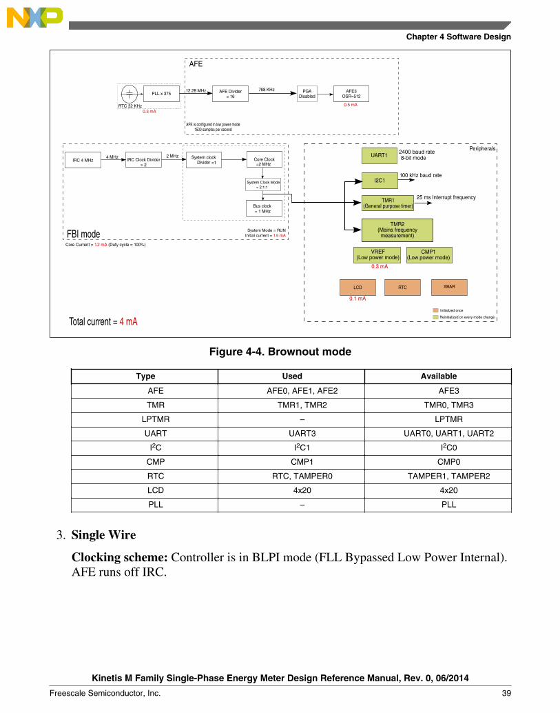
2. Brownout
Clocking scheme: Controller is in BLPI mode (FLL Bypassed Low Power Internal).AFE runs off IRC.
Measurement
Kinetis M Family Single-Phase Energy Meter Design Reference Manual, Rev. 0, 06/2014
38 Freescale Semiconductor, Inc.
Core ClockSystem clock Divider =1 =2 MHz
12.28 MHz
Bus clock
PLL x 375
RTC 32 KHz
AFE is configured in low power mode1500 samples per second
AFE Divider= 16
768 KHz
= 1 MHz
System Clock Mode = 2:1:1
System Mode = RUN
AFE3OSR=512
AFE
0.5 mA
PGA Disabled
0.3 mA
Core Current = 1.2 mA (Duty cycle = 100%)
Initial current = 1.5 mA
Total current = 4 mA
FBI mode
IRC Clock Divider= 2
IRC 4 MHz4 MHz 2 MHz UART1
2400 baud rate8-bit mode
25 ms Interrupt frequency
I2C1
TMR1(General purpose timer)
100 kHz baud rate
Peripherals
VREF(Low power mode)
RTC
CMP1(Low power mode)
XBARLCD
TMR2(Mains frequency
measurement)
0.3 mA
0.1 mA
Initialized once
Reinitialized on every mode change
Figure 4-4. Brownout mode
Type Used Available
AFE AFE0, AFE1, AFE2 AFE3
TMR TMR1, TMR2 TMR0, TMR3
LPTMR – LPTMR
UART UART3 UART0, UART1, UART2
I2C I2C1 I2C0
CMP CMP1 CMP0
RTC RTC, TAMPER0 TAMPER1, TAMPER2
LCD 4x20 4x20
PLL – PLL
3. Single Wire
Clocking scheme: Controller is in BLPI mode (FLL Bypassed Low Power Internal).AFE runs off IRC.
Chapter 4 Software Design
Kinetis M Family Single-Phase Energy Meter Design Reference Manual, Rev. 0, 06/2014
Freescale Semiconductor, Inc. 39

Core ClockSystem clock Divider =1 =2 MHz
2 MHz
Bus clock
AFE is configured in low power mode2000 samples per second
AFE Divider= 2
1 MHz
= 1 MHz
System Clock Mode = 2:1:1
System Mode = VLPR
AFE1 or AFE 2OSR=512
AFE
Peripherals
LPTMR(For pulse generation)
0.5 mA
PGA Disabled
Core Current = 1.2 mA (Duty cycle = 100%)
Initial current = 0.25 mA
Total current = 2.2 mA
BLPI mode
IRC Clock Divider= 2
IRC 4 MHz 4 MHz 2 MHz
MCGIRCLK=2 MHz
UART12400 baud rate8-bit mode
25 ms Interrupt frequency
I2C1
TMR1(General purpose timer)
50 kHz baud rate
VREF(Low power mode)
RTC
CMP1(Low power mode)
XBARLCD
TMR2(Mains frequency
measurement)
0.3 mA
0.1 mA
Initialized once
Reinitialized on every mode changeRTC 32 kHz
RTC
32
kHz
NOTE: Comsumption for other peripherials is negligible
Backlight = Disabled
Figure 4-5. Single wire mode
Type Used Available
AFE AFE0, AFE1 AFE2, AFE3
TMR TMR1, TMR2 TMR0, TMR3
LPTMR LPTMR –
UART UART3 UART0, UART1, UART2
I2C I2C1 I2C0
CMP CMP1 CMP0
RTC RTC, TAMPER0 TAMPER1, TAMPER2
LCD 4x20 4x20
PLL – PLL
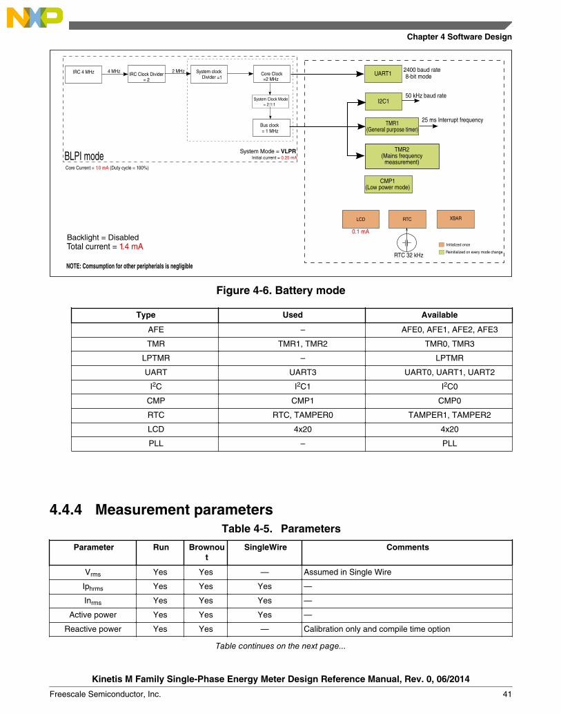
4. Battery
Clocking scheme: Controller is in BLPI mode (FLL Bypassed Low Power Internal).Metrology is disabled.
Measurement
Kinetis M Family Single-Phase Energy Meter Design Reference Manual, Rev. 0, 06/2014
40 Freescale Semiconductor, Inc.
Core ClockSystem clock Divider =1 =2 MHz
Bus clock= 1 MHz
System Clock Mode = 2:1:1
System Mode = VLPR
Core Current = 1.0 mA (Duty cycle = 100%)
Initial current = 0.25 mA
Total current = 1.4 mA
BLPI mode
IRC Clock Divider= 2
IRC 4 MHz 4 MHz 2 MHz UART12400 baud rate8-bit mode
25 ms Interrupt frequency
I2C1
TMR1(General purpose timer)
50 kHz baud rate
RTC
CMP1(Low power mode)
XBARLCD
TMR2(Mains frequency
measurement)
0.1 mA
Initialized once
Reinitialized on every mode changeRTC 32 kHz
Backlight = Disabled
NOTE: Comsumption for other peripherials is negligible
Figure 4-6. Battery mode
Type Used Available
AFE – AFE0, AFE1, AFE2, AFE3
TMR TMR1, TMR2 TMR0, TMR3
LPTMR – LPTMR
UART UART3 UART0, UART1, UART2
I2C I2C1 I2C0
CMP CMP1 CMP0
RTC RTC, TAMPER0 TAMPER1, TAMPER2
LCD 4x20 4x20
PLL – PLL
4.4.4 Measurement parametersTable 4-5. Parameters
Parameter Run Brownout
SingleWire Comments
Vrms Yes Yes — Assumed in Single Wire
Iphrms Yes Yes Yes —
Inrms Yes Yes Yes —
Active power Yes Yes Yes —
Reactive power Yes Yes — Calibration only and compile time option
Table continues on the next page...
Chapter 4 Software Design
Kinetis M Family Single-Phase Energy Meter Design Reference Manual, Rev. 0, 06/2014
Freescale Semiconductor, Inc. 41

Table 4-5. Parameters (continued)
Parameter Run Brownout
SingleWire Comments
Apparent power Yes Yes — —
Power factor Yes Yes — Assumed in Single Wire
Active energy Yes Yes Yes —
Reactive energy Yes Yes — Calibration only and compile time option
Apparent energy Yes Yes Yes —
4.4.5 InitializationThe metering engine requires the following peripherals:
• PLL• AFE• Vref• TMR2• XBAR• CMP1
Depending on the mode metering engine is working on, these peripherals are selectivelyinitialized. CMP1 is always initialized to either detect presence of voltage (for battery andsingle wire modes) or for frequency (brownout and run modes).
Mode Peripheral initialized
Brownout AFE2, AFE1, AFE0, Vref
Run AFE2, AFE1, AFE0, Vref
Battery —
Single Wire AFE0/1, Vref
NOTE
In Single wire mode, the current channels are enabled one at atime to check current on the two channels and use the one that’shigher of the two.
In Battery mode (which is essentially used for display in mainsoff mode), CMP1 is enabled to see if mains supply is restored.
Transition from any mode to another mode is done viabrownout.
RMS is the typical mode of computation.
Measurement
Kinetis M Family Single-Phase Energy Meter Design Reference Manual, Rev. 0, 06/2014
42 Freescale Semiconductor, Inc.

4.4.6 SamplingSamples of the enabled AFE channels are accumulated in data structures for fixedduration, that is, 1 second. At that instance, the sampler triggers metering. Metering istriggered either by sampling count (if PLL is active) or when a second has elapsed (whensource is RTC). Offsets are removed from samples before banks are updated. Sumswhich are updated during sampling are:
• Voltage rms• Phase current rms• Neutral current rms• Active Phase power• Active Neutral power• Reactive Phase power• Reactive Neutral power
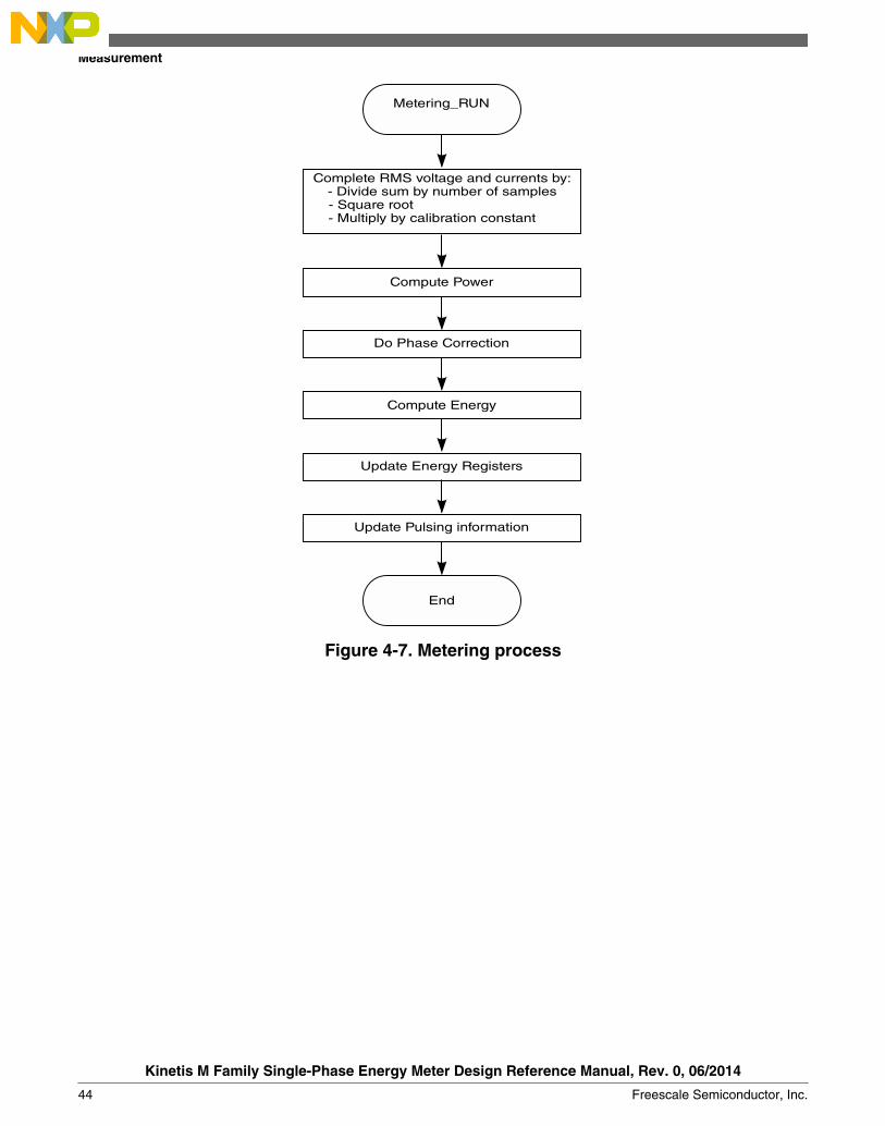
4.4.7 Metering processEvery one second the metering processing engine is triggered. This engine computes thegathered raw samples into metering parameters. The steps involved are (slightly vary fordifferent modes):
1. Scale the gathered sums in 64 bits into floating point.2. Calibration constants are applied. RMS parameters are computed in this step itself as
they don’t need any further calculations.3. Active, Reactive and Apparent powers are computed for phase and neutral elements.
Total powers are also computed.4. Power factor is derived.5. Phase correction is applied (see method below).6. Powers computed are converted into energies. Energy is recorded only in import
mode (always forwarded).7. Energy registers are updated.8. Energy accumulated in this metering period is updated for driving calibration LED.9. Auto-Calibration is invoked, if enabled.
Chapter 4 Software Design
Kinetis M Family Single-Phase Energy Meter Design Reference Manual, Rev. 0, 06/2014
Freescale Semiconductor, Inc. 43
Metering_RUN
Complete RMS voltage and currents by:- Divide sum by number of samples- Square root - Multiply by calibration constant
End
Compute Power
Do Phase Correction
Compute Energy
Update Pulsing information
Update Energy Registers
Figure 4-7. Metering process
Measurement
Kinetis M Family Single-Phase Energy Meter Design Reference Manual, Rev. 0, 06/2014
44 Freescale Semiconductor, Inc.

Apply Phase Correction
End
= cos -1Apparent Power
Active Power( )Power factor
Get sin of power factor from sign of I at zero
cross over of V
If leading PF, Apply Phase Correction
= x -1
Phase Correction= +c '
New active power = App power x cos c
Reactive Power = App Power x sin c
(From calib)
Figure 4-8. Phase error correction
Chapter 4 Software Design
Kinetis M Family Single-Phase Energy Meter Design Reference Manual, Rev. 0, 06/2014
Freescale Semiconductor, Inc. 45
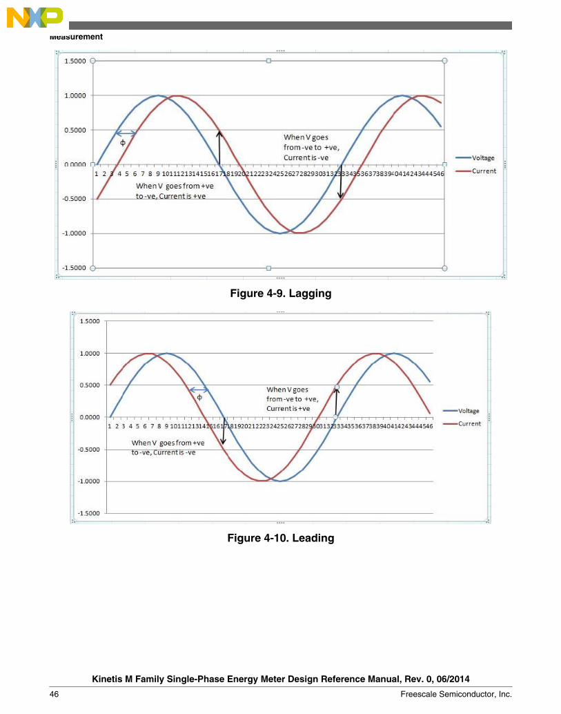
Figure 4-9. Lagging
Figure 4-10. Leading
Measurement
Kinetis M Family Single-Phase Energy Meter Design Reference Manual, Rev. 0, 06/2014
46 Freescale Semiconductor, Inc.

User interface
4.5.1 Introduction
The User Interface Module comprises of LCD, keypad, and LEDs and their respectivedrivers. Custom LCD specific for metering application to displaying various Electricalparameters. Meter has Push button key for manually control the display of parameters.Meter has LED for energies pulse generation. Backlight control of LCD through I/O pincontroller .
Figure 4-11. LCD block diagram
4.5.2 LCD panelThis reference design has a configurable list of parameter to be displayed on the LCD.User will select the list of parameter and the sequence of parameter to be displayed onLCD by controlling the Mask set defines. There are two mode for the display Auto ScrollMode and Manual Scroll Mode. Currently following parameters has been implemented.
• LCD Self Test• Phase current• Neutral current• Voltage• Frequency• Active power
4.5
Chapter 4 Software Design
Kinetis M Family Single-Phase Energy Meter Design Reference Manual, Rev. 0, 06/2014
Freescale Semiconductor, Inc. 47

• Apparent Power• Active Energy (Complete Value)• Maximum Demand (kW)• Maximum demand Time• Maximum demand Date• Power Factor• Real Time• Real Date• Tamper status of meter cover open• Latest Cover Open Tamper event date• Latest Cover Open Tamper event time• Active Energy (Integer value only)• Status of Magnetic Tamper• Latest Magnetic Tamper event date• Latest Magnetic Tamper event time• Cumulative active energy for each calendar month for previous six month with
display of Month• Maximum demand (kW MD) in a calendar month for previous six months with date
and time
NOTEAny parameter in the above list can be configured to display inthe two modes, that is, Auto Scroll Mode and Manual ScrollMode.
4.6 CommunicationMeter facilitates optical port for serial communication, using IEC62056-21 Mode Cprotocol, with external world for data exchange. On personal computer, hyper terminal orany standard windows utility, like InTerm Version 1.1 from RF innovations, is used forcommunication purpose. Transmission and reception takes place by interrupt method.
Communication
Kinetis M Family Single-Phase Energy Meter Design Reference Manual, Rev. 0, 06/2014
48 Freescale Semiconductor, Inc.

Figure 4-12. Optical communication block diagram
4.6.1 Implementation• IEC 62056-21 Mode C protocol is used for data exchange.• An optical head is used for over the optical port interface on the meter and RS232
port connected to PC for communication.• Transmission and reception is on interrupt based. Reception is disabled until the
received packet is processed.• Data verification implemented in programming mode to ensure correct entry of data.• Character Transmission
• Asynchronous serial bit (Start-Stop) transmission• Half duplex communication• Baud rate – 2400, Standard Baud rate – 300, 600, 1200, 2400, 4800, 9600,19200• Character format: 1 start bit, 7 data bits, 1 parity bit, 1 stop bit• Character security: Even Parity
• COM port settings• Baud Rate : 2400 bps• Data Bits : 8• Parity : None• Stop Bit(s) : 1• Flow control : None
• Optical port interface supports following modes• Data Collection Mode: Data collection consists of header information (MFG
identity, unit serial number and name, version, revision etc.), electricalparameters etc
Chapter 4 Software Design
Kinetis M Family Single-Phase Energy Meter Design Reference Manual, Rev. 0, 06/2014
Freescale Semiconductor, Inc. 49

• Programming Mode: This mode is used to configure the following meterparameters and settings.
• Read date, time and configuration parameters.• Program date and time.• Program serial name and number.• Program nominal voltage, current and frequency.• Program MD integration period.• Program auto scroll period.• Program LP interval time.• Program persistence time.• Program optical baud rate.• Program pulse constant.• Clear MD parameters, tamper headers and load profile headers.
• Calibration Mode: Calibration of the meter is done in this mode which includesmanual and auto calibration. Please refer section 4.7 or user guide for details ofcalibration.
NOTESelect odd parity in the com settings to configure for evenparity and vice versa. This is a known bug in the In-TermUtility.
4.7 CalibrationCalibration of the meter is done in order to compensate for variations introduced byhardware. Calibration of the meter can be done in auto calibration method only. In AutoCalibration user feeds a known voltage and current and the software calculates thecoefficients and stores them in NV memory if calibration is successful.
4.7.1 Auto calibration processAuto Calibration Module calibrates the meter for various parameters to compensateerrors due to tolerance of external components. Calibration of the meter is a single pointprocess. The load points are as follows:
• 240 V• 10 A• UPF
Calibration
Kinetis M Family Single-Phase Energy Meter Design Reference Manual, Rev. 0, 06/2014
50 Freescale Semiconductor, Inc.

NOTEThe load point can be changed as the calibration engine cantake any load point.
Once the load point is set, calibration is started. Accumulation happens normally for 10cycles referred as n following in steps. The following flowchart explains the calibrationprocess:
End
Wait for 5 cycles for stabilization
Accumulate Phase Angle
Apply Phase error
Apply Ratio error
Accumulate Magnitude
Start
Figure 4-13. Flow diagram of calibration
Ratio error is elaborated in the following flow diagram:
Chapter 4 Software Design
Kinetis M Family Single-Phase Energy Meter Design Reference Manual, Rev. 0, 06/2014
Freescale Semiconductor, Inc. 51

Measured value = Average Accumulated RMS value
Accumulate RMS value for 5 cycles (V, Iph, IN)
Measured valueApplied value( )New calib co-efficient= x Old calib co-efficient
Figure 4-14. Flow diagram of ratio error
Phase error is elaborated in the following flow diagram:
Accumulate Phase Angle for 5 metering cycles
Average Phase Angle =
Phase Error = Phase Angle - Applied Angle
/ 5
Ph Angle = tan-1(Reactive Power/Active Power)
Figure 4-15. Flow diagram of phase error
4.8 Tamper detectionFollowing Tampers are detectable by the meter:
1. Box Open2. Magnetic3. Phase Reversal4. Partial Earth5. Neutral Missing
Tamper detection
Kinetis M Family Single-Phase Energy Meter Design Reference Manual, Rev. 0, 06/2014
52 Freescale Semiconductor, Inc.

4.8.1 Box Open tamper
Box open tamper switch is mounted on the meter. Each time box cover is open, a tamperis registered in the RTC. This tamper is active even if the main power is OFF. Timestamp of this tamper is also recorded in the RTC. Metering software takes care of thetamper occurrence and release time.
4.8.2 Magnetic tamper
Magnetic tamper is a high magnetic field presence condition near the meter. This tampercondition results in inappropriate functioning of current transformer. A magnetic switchis used in the hardware to detect magnetic tamper condition. Output signal of this switchtoggles whenever magnetic field is applied and this signal is tied with one I/O ofmicrocontroller in GPIO mode, this toggle is detected as a tamper. Magnetic tamper isnot tested on the reference design.
4.8.3 Phase reversal tamper
Phase reversal tamper is a condition in which meter starts registering energy consumptionin negative direction when phase and neutral are reversed. This causes energy units todecrement. So this condition is detected as a tamper in software and energy is alwaystreats as positive. Occurrence and Release time stamp of this tamper is stored inEEPROM.
4.8.4 Partial Earth tamper
Partial earth tamper is a condition in which phase and neutral current are not equal. Apartial amount of current is returned back to local earth. Amount of current returningback in neutral line is not equal to the phase line, rather it is lesser. This tamper conditionis detected in software. Occurrence and release date and time of this tamper is stored inEEPROM.
4.8.5 Neutral Missing tamper
Neutral missing tamper is a condition in which user disconnects the neutral from themeter. This will causes meter to power OFF and user can draw current from the phaseline, which will not be registered in the meter. This condition is taken care by poweringthe meter by an auxiliary power source know as Neutral Missing power CT. So whenever
Chapter 4 Software Design
Kinetis M Family Single-Phase Energy Meter Design Reference Manual, Rev. 0, 06/2014
Freescale Semiconductor, Inc. 53

neutral missing condition occurs, neutral missing power CT will power on the meter andthe current following through phase line will be detected and this condition will also beregistered in EEPROM.
4.9 Database
4.9.1 IntroductionReference Energy Meter design has external serial NV memory interfaced to KM devicesover I2C port. NV memory storage structures are as follows:
• Active, Reactive, and Apparent Energies• Maximum Demand (MD)• Calibration Coefficients• Configuration Parameters• Previous Month MD and Cumulative Energy.• Tamper Headers and Tamper Data• Load Profile Header and Load Profile Data.
The details of each structure can be found in the following excel file.
4.9.2 Assumptions, constraints, and limitations
Meter will be configured with default values if nonvolatile memory gets corrupted.
Database
Kinetis M Family Single-Phase Energy Meter Design Reference Manual, Rev. 0, 06/2014
54 Freescale Semiconductor, Inc.
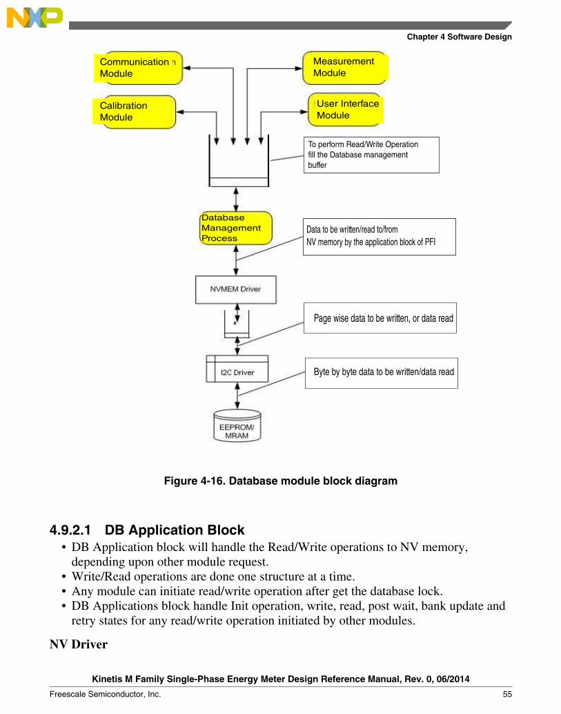
Data to be written/read to/from NV memory by the application block of PFI
To perform Read/Write Operationfill the Database managementbuffer
Page wise data to be written, or data read
Byte by byte data to be written/data read
CalibrationModule
CommunicationModule
MeasurementModule
User InterfaceModule
DatabaseManagementProcess
Figure 4-16. Database module block diagram
4.9.2.1 DB Application Block• DB Application block will handle the Read/Write operations to NV memory,
depending upon other module request.• Write/Read operations are done one structure at a time.• Any module can initiate read/write operation after get the database lock.• DB Applications block handle Init operation, write, read, post wait, bank update and
retry states for any read/write operation initiated by other modules.
NV Driver
Chapter 4 Software Design
Kinetis M Family Single-Phase Energy Meter Design Reference Manual, Rev. 0, 06/2014
Freescale Semiconductor, Inc. 55

• NV driver will receive a read/write request from the DB Application block.• Based on type of NV memory, write operation will be executed.• EEPROM paging concept (maximum of 128 bytes write at a time) will be executed.• NV driver will call I2C drivers for read/write operation.
I2C Driver• I2C driver will write and read the data to and from NV memory
4.9.3 Implementation• The module which needs to access NV memory should first obtain LOCK. Only one
module can access NV memory at a time. In case the lock is unavailable therequesting module can either wait until lock is released or can terminate the requestby itself.
• Transmission and reception over I2C are interrupt based.• I2C baud rate configured for EEPROM is 100 kHz.• NV Read/Write Success – Database application block returns DB_SUCCESS and
releases the lock• NV Read/Write Failure – The application retries the read/write operation for 3 times
in case of failure. If read/write is unsuccessful for retry number of counts thendatabase application block returns DB_FAILURE and releases the lock.
• Active Energy and status of various Tampers will be saved in RTC nonvolatilememory at a fixed interval of 1 min
• At the time of power up latest energy from RTC Ram is copied into EEPROM onactive bank of energy structure.
• At power ON application validates the signature of current bank. If either of the banksignatures is valid, application reads Energies, Maximum Demand Parameters, loadprofile, Configuration Parameters , Calibration Parameters, Previous Month MD andEnergy headers and tamper headers from NV memory. If both the bank signaturesare invalid then defaults are written to NV memory.
• CRC check for each structure for data integrity.
4.9.4 Memory map
EEPROM Size = 64 Kbytes
Table 4-7. NV memory details
Structure Bytes
Bank Status and Signature for each bank 10
Table continues on the next page...
Database
Kinetis M Family Single-Phase Energy Meter Design Reference Manual, Rev. 0, 06/2014
56 Freescale Semiconductor, Inc.

Table 4-7. NV memory details (continued)
Number of bytes required by Energy Registers 64
Number of bytes required by Maximum demand 32
Number of bytes required by Calibration coefficients 64
Number of bytes required by Configuration parameters 96
Number of Bytes Required MD and Energy CumulativeHeader
10
Number of Bytes Required MD and Energy Cumulative DataPart
192
Number of Bytes Required Reverse Tamper Header 12
Number of Bytes Required Reverse Tamper Data 1100
Number of Bytes Required Earth Tamper Header 12
Number of Bytes Required Earth Tamper Data 1100
Number of Bytes Required Magnetic Tamper Header 12
Number of Bytes Required magnetic Tamper Data 1100
Number of Bytes Required Cover Tamper Header 12
Number of Bytes Required Cover Tamper Data 1100
Number of Bytes Required Neutral Missing Tamper Header 12
Number of Bytes Required Neutral Missing Tamper Data 1100
Number of bytes required by Load profile 25938
Total number in Bytes 37512
Total number in Kbytes 36.633
4.9.5 State Machines / Control Charts
Following figure describes the state diagram of Database Communication on EEPROM.
Chapter 4 Software Design
Kinetis M Family Single-Phase Energy Meter Design Reference Manual, Rev. 0, 06/2014
Freescale Semiconductor, Inc. 57
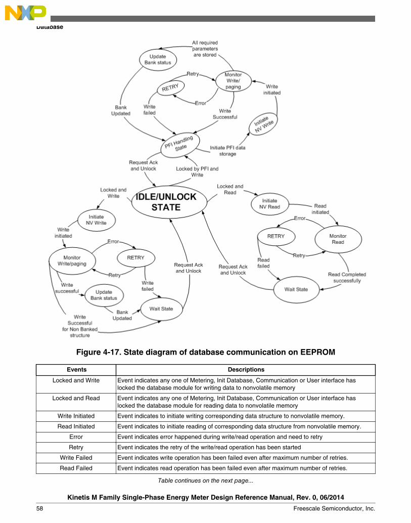
Figure 4-17. State diagram of database communication on EEPROM
Events Descriptions
Locked and Write Event indicates any one of Metering, Init Database, Communication or User interface haslocked the database module for writing data to nonvolatile memory
Locked and Read Event indicates any one of Metering, Init Database, Communication or User interface haslocked the database module for reading data to nonvolatile memory
Write Initiated Event indicates to initiate writing corresponding data structure to nonvolatile memory.
Read Initiated Event indicates to initiate reading of corresponding data structure from nonvolatile memory.
Error Event indicates error happened during write/read operation and need to retry
Retry Event indicates the retry of the write/read operation has been started
Write Failed Event indicates write operation has been failed even after maximum number of retries.
Read Failed Event indicates read operation has been failed even after maximum number of retries.
Table continues on the next page...
Database
Kinetis M Family Single-Phase Energy Meter Design Reference Manual, Rev. 0, 06/2014
58 Freescale Semiconductor, Inc.

Events Descriptions
Write Successful Write operation of banked structure is successfully over and bank status has to be updated
Read Successful Read operation is successfully over release of database module has to be done
Write Successful for non-banked structure
Write operation of non banked structure is successfully over and release of database modulehas to be done
Bank Updated Bank status structure is updated for corresponding banked structure and written into nonvolatilememory.
Request ACK and UnLock Indicates respective module that write/read operation done and request to release databasemodule
4.9.6 Maximum demandMaximum Demand Register
• Meter will record the Maximum Demand (kW MD) with time stamp in non-volatilememory.
• Maximum demand will be calculated from accumulated imported/exported Activeenergy for MD interval.
• Maximum Demand and Cumulative Energy for previous six months will be stored inEEPROM
• Configurable MD integration time – 30 and 60 minutes
Maximum Demand Calculation – Fixed Window Method• At the end of each fixed integration period, average power for that period is
calculated. If this value is greater than the already existing MD value then this isstored as new MD.
• MD value is cleared in NV memory whenever there is change in date, time or MDintegration period.
MD Reset• MD reset by serial communication (optical port). All the MD parameters will be
cleared in NV memory.• MD can be read through serial communication (optical port) with the help of AMR
protocol utility.
MD parameters stored in NV memory
Following parameters are stored in non-volatile memory:• Maximum Demand (kW)• MD Date and Time
Chapter 4 Software Design
Kinetis M Family Single-Phase Energy Meter Design Reference Manual, Rev. 0, 06/2014
Freescale Semiconductor, Inc. 59
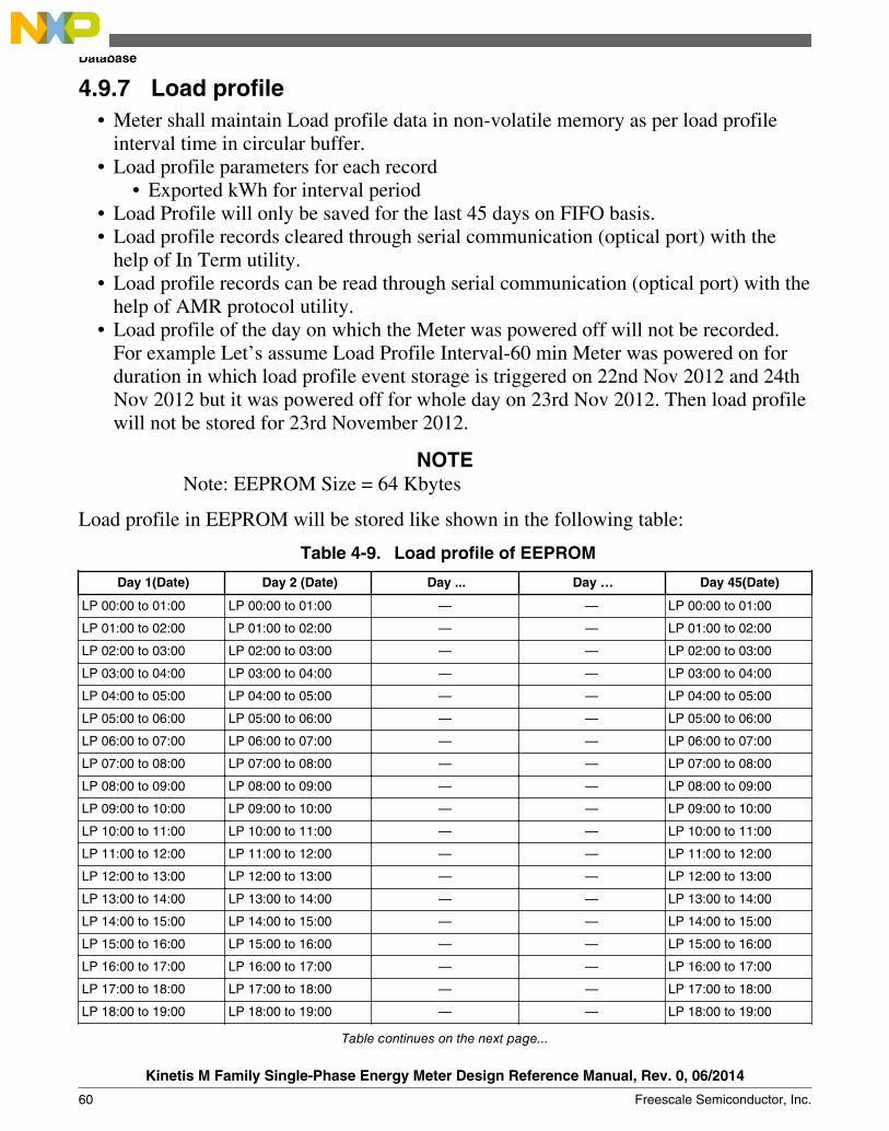
4.9.7 Load profile• Meter shall maintain Load profile data in non-volatile memory as per load profile
interval time in circular buffer.• Load profile parameters for each record
• Exported kWh for interval period• Load Profile will only be saved for the last 45 days on FIFO basis.• Load profile records cleared through serial communication (optical port) with the
help of In Term utility.• Load profile records can be read through serial communication (optical port) with the
help of AMR protocol utility.• Load profile of the day on which the Meter was powered off will not be recorded.
For example Let’s assume Load Profile Interval-60 min Meter was powered on forduration in which load profile event storage is triggered on 22nd Nov 2012 and 24thNov 2012 but it was powered off for whole day on 23rd Nov 2012. Then load profilewill not be stored for 23rd November 2012.
NOTENote: EEPROM Size = 64 Kbytes
Load profile in EEPROM will be stored like shown in the following table:
Table 4-9. Load profile of EEPROM
Day 1(Date) Day 2 (Date) Day ... Day … Day 45(Date)
LP 00:00 to 01:00 LP 00:00 to 01:00 — — LP 00:00 to 01:00
LP 01:00 to 02:00 LP 01:00 to 02:00 — — LP 01:00 to 02:00
LP 02:00 to 03:00 LP 02:00 to 03:00 — — LP 02:00 to 03:00
LP 03:00 to 04:00 LP 03:00 to 04:00 — — LP 03:00 to 04:00
LP 04:00 to 05:00 LP 04:00 to 05:00 — — LP 04:00 to 05:00
LP 05:00 to 06:00 LP 05:00 to 06:00 — — LP 05:00 to 06:00
LP 06:00 to 07:00 LP 06:00 to 07:00 — — LP 06:00 to 07:00
LP 07:00 to 08:00 LP 07:00 to 08:00 — — LP 07:00 to 08:00
LP 08:00 to 09:00 LP 08:00 to 09:00 — — LP 08:00 to 09:00
LP 09:00 to 10:00 LP 09:00 to 10:00 — — LP 09:00 to 10:00
LP 10:00 to 11:00 LP 10:00 to 11:00 — — LP 10:00 to 11:00
LP 11:00 to 12:00 LP 11:00 to 12:00 — — LP 11:00 to 12:00
LP 12:00 to 13:00 LP 12:00 to 13:00 — — LP 12:00 to 13:00
LP 13:00 to 14:00 LP 13:00 to 14:00 — — LP 13:00 to 14:00
LP 14:00 to 15:00 LP 14:00 to 15:00 — — LP 14:00 to 15:00
LP 15:00 to 16:00 LP 15:00 to 16:00 — — LP 15:00 to 16:00
LP 16:00 to 17:00 LP 16:00 to 17:00 — — LP 16:00 to 17:00
LP 17:00 to 18:00 LP 17:00 to 18:00 — — LP 17:00 to 18:00
LP 18:00 to 19:00 LP 18:00 to 19:00 — — LP 18:00 to 19:00
Table continues on the next page...
Database
Kinetis M Family Single-Phase Energy Meter Design Reference Manual, Rev. 0, 06/2014
60 Freescale Semiconductor, Inc.

Table 4-9. Load profile of EEPROM (continued)
Day 1(Date) Day 2 (Date) Day ... Day … Day 45(Date)
LP 19:00 to 20:00 LP 19:00 to 20:00 — — LP 19:00 to 20:00
LP 20:00 to 21:00 LP 20:00 to 21:00 — — LP 20:00 to 21:00
LP 21:00 to 22:00 LP 21:00 to 22:00 — — LP 21:00 to 22:00
LP 22:00 to 23:00 LP 22:00 to 23:00 — — LP 22:00 to 23:00
LP 23:00 to 00:00 LP 23:00 to 00:00 — — LP 23:00 to 00:00
Number of Load profile entries for 45 days depending on the load profile interval is givenin the following table:
Load Profile Interval Number of Entries in a day Total Entries for 45 days
15 min 96 4320
30 min 48 2160
60 min 24 1080
Chapter 4 Software Design
Kinetis M Family Single-Phase Energy Meter Design Reference Manual, Rev. 0, 06/2014
Freescale Semiconductor, Inc. 61

Database
Kinetis M Family Single-Phase Energy Meter Design Reference Manual, Rev. 0, 06/2014
62 Freescale Semiconductor, Inc.

Chapter 5Revision history
5.1 Revision historyRevision number Date Substantial changes
0 06/2015 Initial release
Kinetis M Family Single-Phase Energy Meter Design Reference Manual, Rev. 0, 06/2014
Freescale Semiconductor, Inc. 63

Revision history
Kinetis M Family Single-Phase Energy Meter Design Reference Manual, Rev. 0, 06/2014
64 Freescale Semiconductor, Inc.
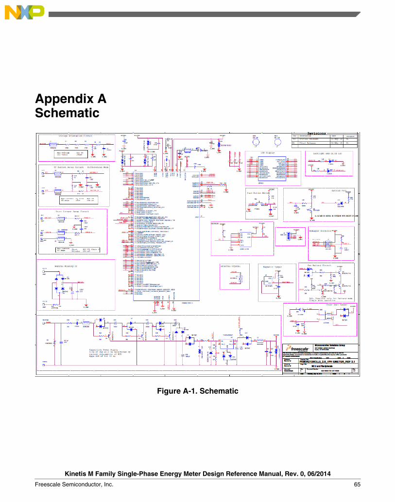
Appendix ASchematic
Figure A-1. Schematic
Kinetis M Family Single-Phase Energy Meter Design Reference Manual, Rev. 0, 06/2014
Freescale Semiconductor, Inc. 65

Kinetis M Family Single-Phase Energy Meter Design Reference Manual, Rev. 0, 06/2014
66 Freescale Semiconductor, Inc.

Appendix BBill of materials
Table B-1. Bill of matirial
Item Quantity AgilePN ASSY_OPT
Reference
Value Description
ASSY_NOTE
MfgName
Mfg PartNumber
PCBFootprint
1 2 801-76144 — BT1,BT2 CR-2032 BATTERYLITHIUMCOINCELL 3VTH
— PANASONIC
CR-2032/VCN
bat_2032_th
2 7 210-79145 DNP SH1,P_CT1,CT1,SH2,P_CT2,CT2,GND
TP TESTPOINTPIN0.062X0.086 TH, NOPART TOORDER
— N/A N/A tp_062_086mil_th
3 2 150-76752 — C1,C19 0.01 µF CAP CER0.01 µF250V 10%X7R 0805
— KEMET C0805C103KARACTU
CC0805_OV
4 17 150-75599 — C2,C3,C4,C5,C6,C7,C8,C10,C12,C18,C20,C27,C29,C31,C33,C34,C37
0.1 µF CAP CER0.1 µF25V 10%X7R 0805
— PANASONIC-ECG
ECJ-2VB1E104K
CC0805_OV
5 6 150-75594 — C9,C13,C15,C16,C30,C36
1.0 µF CAP CER1.0 µF10V 10%X7R 0805
— SMEC MCCB105K2NRTF
CC0805_OV
6 1 150-30192 — C17 470 µF CAP ALEL470 µF35V 20%-- RADIAL
— Nichicon UPW1V471MPD
c413_rad_pol
7 1 150-78638 — C21 0.22 µF CAPMETPLY0.22 µF250VAC10% --RADIAL
— PANASONIC
ECQU2A224KLA
cr709_335
Table continues on the next page...
Kinetis M Family Single-Phase Energy Meter Design Reference Manual, Rev. 0, 06/2014
Freescale Semiconductor, Inc. 67

Table B-1. Bill of matirial (continued)
Item Quantity AgilePN ASSY_OPT
Reference
Value Description
ASSY_NOTE
MfgName
Mfg PartNumber
PCBFootprint
8 1 150-77050 — C22 100 µF CAP ALEL100 µF10V 20%-- THRADIAL
— PANASONIC
ECA1AM101I
cap_rad_6p3mm_7mm
9 1 150-78780 — C23 220 µF CAP ALEL220 µF16V 20%-- RADIAL
— LELONELECTRONICSCORP
REA221M1CTAF0611
CAP_RAD_6P3_11MM
10 1 150-30094 — C24 330 µF CAP ALEL330 µF25V 20%-- RADIAL
— PANASONIC
ECA1EM331
C335_RAD
11 1 150-78705 — C25 0.01 µF CAP CER0.01 µF2000V20% Z5URADIAL
— VISHAYINTERTECHNOLOGY
S103M69Z5UP63K7R
cr690_160
12 2 150-75661 — C26,C32 10 µF CAP ALEL10 µF 16V20% --RADIAL
— NICHICON
UVR1C100MDD
c079_rad_pol
13 1 150-76873 — C28 1000 µF CAP ALEL1000 µF10V 20%-- THRADIAL
— PANASONIC
ECA1AM102
c197_rad_pol
14 1 370-76530 <ASSY_OPT>
DS1 DP7013 LCD TNDISPLAY3V 24 PINTH
— DEEPAKSHIDISPLAYDEVICESPVT. LTD
DP7013 lcd_24_2p_th
15 1 370-76510 DNP D1 L-53LID LED REDSGL 2MATH
— KINGBRIGHT
L-53LID led_2_6
16 1 370-76510 — D2 L-53LID LED REDSGL 2MATH
— KINGBRIGHT
L-53LID led_2_6
17 11 480-75079 — D3,D4,D5,D6,D7,D8,D9,D10,D11,D12,D15
BAT54S DIODEDUALSCH200MA30VSOT23
— FAIRCHILD
BAT54S SOT-23
18 1 480-78316 — D13 BZV55-C5V6,115
DIODEZNR 5.6V500MWSOD80C
— NXPSemiconductors
BZV55-C5V6,115
sod80c
Table continues on the next page...
Kinetis M Family Single-Phase Energy Meter Design Reference Manual, Rev. 0, 06/2014
68 Freescale Semiconductor, Inc.
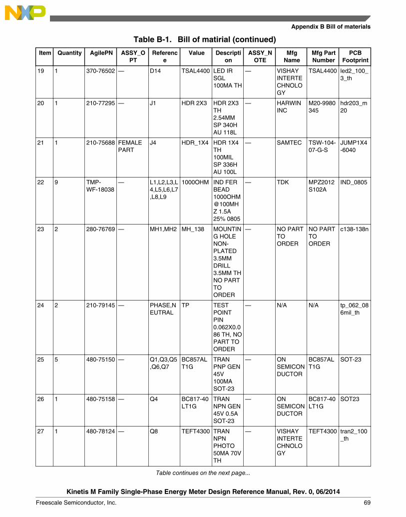
Table B-1. Bill of matirial (continued)
Item Quantity AgilePN ASSY_OPT
Reference
Value Description
ASSY_NOTE
MfgName
Mfg PartNumber
PCBFootprint
19 1 370-76502 — D14 TSAL4400 LED IRSGL100MA TH
— VISHAYINTERTECHNOLOGY
TSAL4400 led2_100_3_th
20 1 210-77295 — J1 HDR 2X3 HDR 2X3TH2.54MMSP 340HAU 118L
— HARWININC
M20-9980345
hdr203_m20
21 1 210-75688 FEMALEPART
J4 HDR_1X4 HDR 1X4TH100MILSP 336HAU 100L
— SAMTEC TSW-104-07-G-S
JUMP1X4-6040
22 9 TMP-WF-18038
— L1,L2,L3,L4,L5,L6,L7,L8,L9
1000OHM IND FERBEAD1000OHM@100MHZ 1.5A25% 0805
— TDK MPZ2012S102A
IND_0805
23 2 280-76769 — MH1,MH2 MH_138 MOUNTING HOLENON-PLATED3.5MMDRILL3.5MM THNO PARTTOORDER
— NO PARTTOORDER
NO PARTTOORDER
c138-138n
24 2 210-79145 — PHASE,NEUTRAL
TP TESTPOINTPIN0.062X0.086 TH, NOPART TOORDER
— N/A N/A tp_062_086mil_th
25 5 480-75150 — Q1,Q3,Q5,Q6,Q7
BC857ALT1G
TRANPNP GEN45V100MASOT-23
— ONSEMICONDUCTOR
BC857ALT1G
SOT-23
26 1 480-75158 — Q4 BC817-40LT1G
TRANNPN GEN45V 0.5ASOT-23
— ONSEMICONDUCTOR
BC817-40LT1G
SOT23
27 1 480-78124 — Q8 TEFT4300 TRANNPNPHOTO50MA 70VTH
— VISHAYINTERTECHNOLOGY
TEFT4300 tran2_100_th
Table continues on the next page...
Appendix B Bill of materials
Kinetis M Family Single-Phase Energy Meter Design Reference Manual, Rev. 0, 06/2014
Freescale Semiconductor, Inc. 69
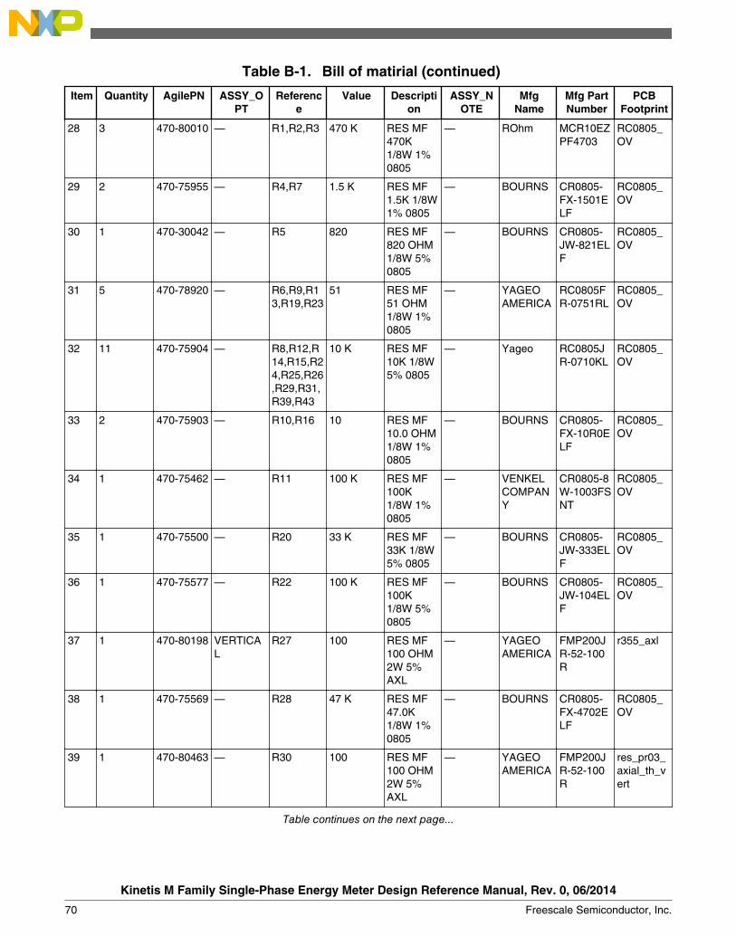
Table B-1. Bill of matirial (continued)
Item Quantity AgilePN ASSY_OPT
Reference
Value Description
ASSY_NOTE
MfgName
Mfg PartNumber
PCBFootprint
28 3 470-80010 — R1,R2,R3 470 K RES MF470K1/8W 1%0805
— ROhm MCR10EZPF4703
RC0805_OV
29 2 470-75955 — R4,R7 1.5 K RES MF1.5K 1/8W1% 0805
— BOURNS CR0805-FX-1501ELF
RC0805_OV
30 1 470-30042 — R5 820 RES MF820 OHM1/8W 5%0805
— BOURNS CR0805-JW-821ELF
RC0805_OV
31 5 470-78920 — R6,R9,R13,R19,R23
51 RES MF51 OHM1/8W 1%0805
— YAGEOAMERICA
RC0805FR-0751RL
RC0805_OV
32 11 470-75904 — R8,R12,R14,R15,R24,R25,R26,R29,R31,R39,R43
10 K RES MF10K 1/8W5% 0805
— Yageo RC0805JR-0710KL
RC0805_OV
33 2 470-75903 — R10,R16 10 RES MF10.0 OHM1/8W 1%0805
— BOURNS CR0805-FX-10R0ELF
RC0805_OV
34 1 470-75462 — R11 100 K RES MF100K1/8W 1%0805
— VENKELCOMPANY
CR0805-8W-1003FSNT
RC0805_OV
35 1 470-75500 — R20 33 K RES MF33K 1/8W5% 0805
— BOURNS CR0805-JW-333ELF
RC0805_OV
36 1 470-75577 — R22 100 K RES MF100K1/8W 5%0805
— BOURNS CR0805-JW-104ELF
RC0805_OV
37 1 470-80198 VERTICAL
R27 100 RES MF100 OHM2W 5%AXL
— YAGEOAMERICA
FMP200JR-52-100R
r355_axl
38 1 470-75569 — R28 47 K RES MF47.0K1/8W 1%0805
— BOURNS CR0805-FX-4702ELF
RC0805_OV
39 1 470-80463 — R30 100 RES MF100 OHM2W 5%AXL
— YAGEOAMERICA
FMP200JR-52-100R
res_pr03_axial_th_vert
Table continues on the next page...
Kinetis M Family Single-Phase Energy Meter Design Reference Manual, Rev. 0, 06/2014
70 Freescale Semiconductor, Inc.

Table B-1. Bill of matirial (continued)
Item Quantity AgilePN ASSY_OPT
Reference
Value Description
ASSY_NOTE
MfgName
Mfg PartNumber
PCBFootprint
40 3 470-80220 — R32,R33,R34
39 K RES MF39K 1/8W1% 0805
— VISHAYINTERTECHNOLOGY
CRCW080539K0FKEA
RC0805_OV
41 1 470-75937 — R35 22 RES MF22 OHM1/8W 5%0805
— BOURNS CR0805-JW-220ELF
RC0805_OV
42 1 470-30372 — R36 510 RES MF510 OHM1/10W 1%0805
— SMEC RC73A2A5100FTF
RC0805_OV
43 1 470-75989 — R37 1.0 K RES MF1.0K 1/8W5% 0805
— ROHM MCR10EZPJ102
RC0805_OV
44 1 470-75585 — R42 15 K RES MF15K 1/8W5% 0805
— BOURNS CR0805JW153ELF
RC0805_OV
45 1 470-76111 — R44 0 Ω RES 0.0OHM1/8W 5%0805 SMD
— YAGEO(VA) V
RC0805JR-070RL
RC0805_OV
46 1 470-75904 DNP R45 10 K RES MF10K 1/8W5% 0805
— Yageo RC0805JR-0710KL
RC0805_OV
47 1 510-75922 — SW1 PTS645 SW SPSTMOM NOPB 12V50MASMT
— ITTCANNON
PTS645SL50SMTRLFS
sw4_pb_6x6_sm
48 1 510-77868 — SW2 ESP2266 SW DPDTPB 30V0.1A THNONROHSCOMPLIANT
— ELCON(INDIA)
ESP2266 sw6_pb_th_esp2266
49 1 TMP-WF-18040
— TVS1 SMCJ14CA
DIODETVS 14V1500WBIDIR 5%SMC
— LITTELFUSE
SMCJ14CA
do-214ab
50 5 TMP-WF-18039
— TVS2,TVS3,TVS4,TVS5,TVS6
CDDFN2-T3.3LC
DIODETVSBIDIR3.3V 5ASMD
— Bourns CDDFN2-T3.3LC
dfn2_0p85_1x0p6
51 1 315-79304 — U1 AH180-WG
IC SWSENSOROMNIPOL
— DIODESINC
AH180-WG-7
sc59
Table continues on the next page...
Appendix B Bill of materials
Kinetis M Family Single-Phase Energy Meter Design Reference Manual, Rev. 0, 06/2014
Freescale Semiconductor, Inc. 71

Table B-1. Bill of matirial (continued)
Item Quantity AgilePN ASSY_OPT
Reference
Value Description
ASSY_NOTE
MfgName
Mfg PartNumber
PCBFootprint
AR HALL-EFFECT2.5-5.5VSC59
52 1 TMP-WF-16914
— U2 PKM34Z128CLL5
IC MCUFLASH128K 16K50MHZ1.71-3.6VLQFP100
— FREESCALESEMICONDUCTOR
PKM34Z128CLL5
LQFP100_0P5_14X14
53 1 TMP-WF-17901
— U3 24AA512-I/SN
IC MEMEEPROM512K400KHZ1.7-5.5VSOIC8
— MicrochipTechnology
24AA512-I/SN
so8_1p27_4x5
54 1 315-79519 — U4 TLV70433DBVT
IC VREGLDO 3.3V150MA2.5-24VSOT23-5
— TEXASINSTRUMENTS
TLV70433DBVT
SOT-23-5
55 1 470-79747 — U5 S10K250E2
VARISTOR250VRMS10% 0.4WRADIAL
— EPCOS B72210S2251K101
varistor_12x5p2mm
56 1 230-76376 — Y1 32.768KHZ
XTAL32.768KHZ -- SMT
— EPSONELECTRONICS
FC-14532.7680KA-A3
xtal_4_1x1_5mm_2p
Kinetis M Family Single-Phase Energy Meter Design Reference Manual, Rev. 0, 06/2014
72 Freescale Semiconductor, Inc.

Appendix CConnection diagramPlease refer following picture of the enclosure
Figure C-1. Connection diagram
Kinetis M Family Single-Phase Energy Meter Design Reference Manual, Rev. 0, 06/2014
Freescale Semiconductor, Inc. 73
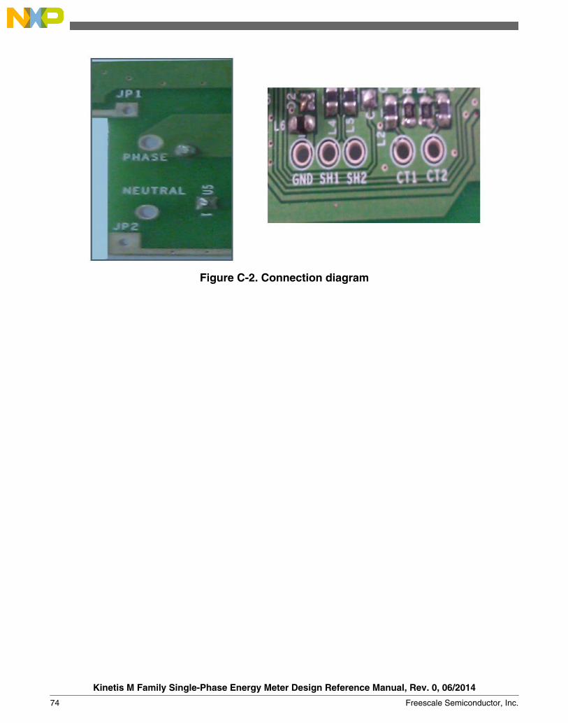
Figure C-2. Connection diagram
Kinetis M Family Single-Phase Energy Meter Design Reference Manual, Rev. 0, 06/2014
74 Freescale Semiconductor, Inc.

How to Reach Us:
Home Page:freescale.com
Web Support:freescale.com/support
Information in this document is provided solely to enable system andsoftware implementers to use Freescale products. There are no expressor implied copyright licenses granted hereunder to design or fabricateany integrated circuits based on the information in this document.Freescale reserves the right to make changes without further notice toany products herein.
Freescale makes no warranty, representation, or guarantee regardingthe suitability of its products for any particular purpose, nor doesFreescale assume any liability arising out of the application or use ofany product or circuit, and specifically disclaims any and all liability,including without limitation consequential or incidental damages.“Typical” parameters that may be provided in Freescale data sheetsand/or specifications can and do vary in different applications, andactual performance may vary over time. All operating parameters,including “typicals,” must be validated for each customer application bycustomer's technical experts. Freescale does not convey any licenseunder its patent rights nor the rights of others. Freescale sells productspursuant to standard terms and conditions of sale, which can be foundat the following address: freescale.com/SalesTermsandConditions.
Freescale, the Freescale logo, Energy Efficient Solutions logo, andKinetis are trademarks of Freescale Semiconductor, Inc., Reg. U.S. Pat.& Tm. Off. All other product or service names are the property of theirrespective owners. ARM and Cortex are registered trademarks of ARMLimited (or its subsidiaries) in the EU and/or elsewhere. All rightsreserved.
© 2014 Freescale Semiconductor, Inc.
Document Number DRM142Revision 0, 06/2014