Embed Size (px)
Citation preview

KINGSBURY BEARINGS
for Turbines,
Steam and Gas
Bulletin T


Printed in U.S.A.
KINGSBURY Thrust and Journal
BEARINGS for
TURBINES
Steam and Gas
BULLETIN T
KINGSBURY MACHINE WORKS, INC. Main Office and Works
FRANKFORD, PHILADELPHIA 24, PA.

CONTENTS Foreword .... Turbine Th rust Bearing Requirements Basic Elements . . . The Shoes and Their Backing . . . . Types of Bearings Described The Oil Control Ring-What ft Does. Oil Control Ring Bearings Two-Collar Type Bearings . Cage Type Thrust Bearings One-Way Thrusts . Vertical Turbine Thrusts . . Lubrication and Cooling . Symbols for Standard Designs Journal Bearings. Spare Parts . . Data Needed for Inquiries Standard Guarantee
J
6 7 7
IO 11 12 13 14 16 17 19 20 22 24 24 24
C(i(cy Cre:ek Uttic No. 1, Z1726~kw crou,compouod turbine ~cne-r.1.tor unit , .H.I\ curbinc 1600 rpm, L.P, lt1r-bine ISOQ rp:m.
Pho tos. court c~y A.r-Aencs.n G .. t \: & Electric Scrvi=e Corp and th .: General f:Jcc tric C,0.

FOREWORD The turbine is essentially a high-speed continuous service
machine which poses some of the most difficult problems of control and lubrication met with in the prime mover field. Whether driven by steam or gas, the operating conditions imposed by the requirements of efficiency and compactness involve high temperatures at the inlet end, resulting in transfer of heat to all parts adjacent to the cylinder structure. In consequence the thrust and journal bearings at the inlet end of such a machine are subjected not only to the heat equivalent of bearing friction, but also to the heat transmitted from the turbine casing.
Under these severe conditions Kingsbury bearings outperform all other types. As an inherent feature of their design, a continuous flow of oil passes between the working surfaces, separating them and preventing metallic contact, also carrying away the heat of friction and transmitted heat. A variety of bearing types and arrangements is supplied to meet different conditions of size, speed and installation.
This booklet is devoted specifically to thrust bearings and journal bearings suitable for this type of application, either land or marine, both in horizontally disposed units of any size and in small vertical units such as are employed in high-speed pump and blower drives.
~1eramcc- St-ation Unir No~ l. I 10,000-kw rand('m compound 1urbln.c liCen<:-rctfor unit. tdple flow. Union Electric Co .. Sr. Lou!., ?t..{o~
rhoto, CO\Ort<SY Westtl'\at,,,use Electric Corp.
Bulletin
T

TURBINE THRUST BEARING REQUIREMENTS
There are two principal requirements which must he met by any bearing used in a steam or gas turbine application. The first is: the abi Ii ty to carry load without distress as long as the turbine remains in operation. This 1s readily fulfilled by Kingsbury Thrust and journal Bearings as long as an adequate supply of cool lubricating; oil is fed to the operating surfaces. Because it is characteristic of the design that the stationary and moving; surfaces are always separated by continuously self-renewing oil films, there is no metallic contact in normal operation and hence no wear. Operating; maintenance is confined to furnishing; the required Aow of clean filtered oil, properly cooled.
The second requirement is that the power loss in the bearing shall be kept to the smallest practicable value. Th1s requirement, for any given application, is met by choosing; that one of the several available styles of bearing that is most suitable for the load and speed involved, so as to min1m1ze unnecessary churning and heating of the oil.
A third requirement is accessibility. [n this respect no other type of bearing can rival the Kingsbury because, where necessary, a split construction can be used so that the thrust bearing parts can be inspected or removed without lifting the turbine shaft .
T ·ypic.11 turbLO'-' •drh1 en .. u11ilbuy unlu.
Bulletin
T
BASIC ELEMENTS The basic elements of a Kingsbury Thrust Bearing are :
(1) The stationary pivoted Shoes. (2) The Thrust Collar, which rotates with the
shaft and applies the load to the shoes (called Runner in vertical bearings).
(3) The Bav Ring or other means of supporting the shoes and equalizing the shoe loads.
(4) The !lousing, or mounting, which contains and supports the internal bearing elements.
(5) The Lubricatio n Systt'ln, which continuously noods the co Ila r and s hoes with oil.
(6) The Cooling Systt'm for removing the heat caused b y oil friction.
Every thrust bearing installation involves all of these elements in one form or another. D es igns may be class ified as horizontal or vertical, and according to the number of shoes .
THE SHOES AND THEIR BACKING Before passing on to the various combinations
of the above elements in particular types of bearings, the general form of the shoes should be noted; also the different methods of supporting them and dividing the load among them.
The Shoes
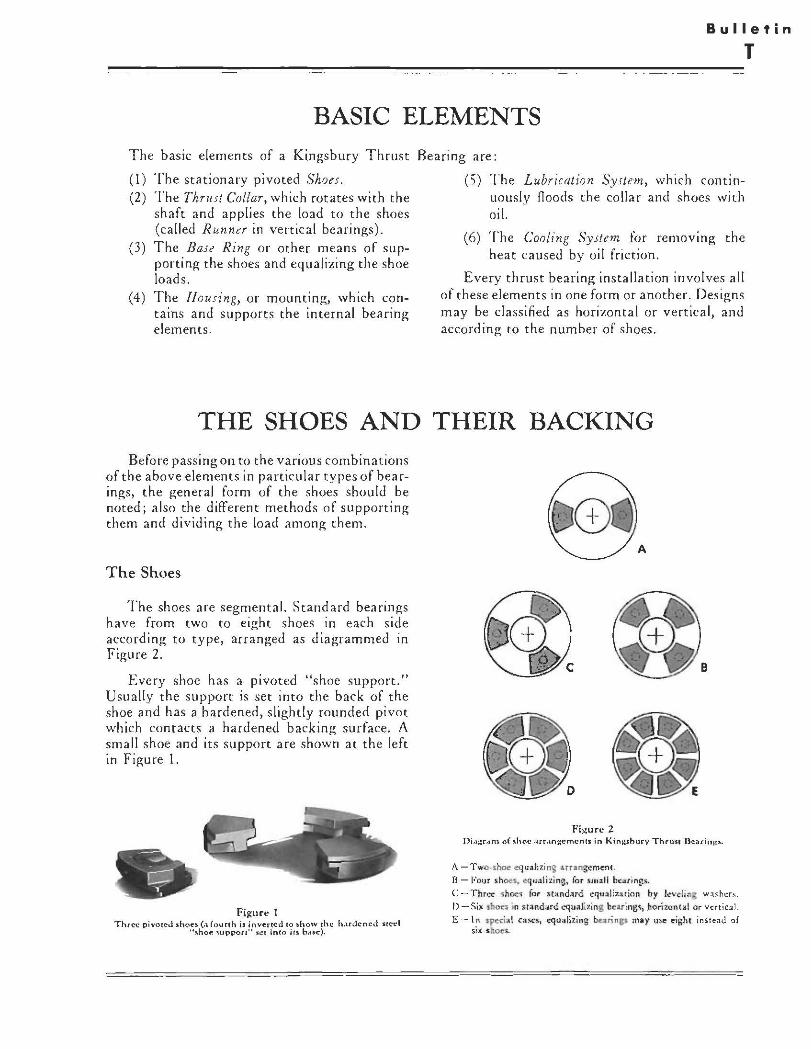
The shoes are segmental. Standard bearings have from two to eight shoes in each side according to type, arranged as diagrammed in Figure 2.
Every shoe has a pivoted "shoe support." Usually the support is set into the back of the shoe and has a hardened, slighdy rounded pivot which contacts a hardened backing surface. A small shoe and its support are shown at the left in Figure 1.
Figure t Thrtt p1vot~J !lhou (a fourch ,, ;nvertcd 10 ,how the h,udcne<l ,ucd
" ... ho(:: -.uppor1° "l'°I ln(o ir~ base).
Figure 2 Di.1;.:r.,n\ of .• ,J,cc <trran~c mcnc s: in Ki n>;s: h ury Thru~n Bc-o1rinl!"·
ii. -Two, ,i',o., eq u, lizinS • rr•ngcmcn1. ll - Four , hO<!s • ..q,:al izing, for sma ll bcar in[ts,
C -Three ~hoes tor st:ind,,rd cqu:11 :z:u ion by leveling washers. 1)-Si• thou ·m sranddr<.! c'<juali,ing l" uin&~, horizont,I or ,·atical. E ~ 1" ipc,:ial case, , equa lizing banng, may use oigh1 inste:i<l af
si.< •h~•.

Equalizing Bearings
Two principal methods of equalization are used. They are illustrated in Figures 4-9.
Fi(?.ure J S1.1nda rct (rcm<.11,•:·thlc) colbr for hcarini::• witl, horiront,1l
,h.dt.
Fii:;ure 5 Thrcc,-.hoe hc~a rin~. For ,•errical o r h ori•
,ont~l ,h .,ft.
Figure 4 St.tnd~rd thrct--•hnc equali,in;: be .. rin~ with .shoC".I removed, ihuwinQ: hardened i1ccl aupport plui:,,.
in ,hoc c.-1.:-c.
Fii;:urc 6 '),,hoc hc;,f'"i n ~ for vc:rt i \:'.,d sh•(t. Ar• rows ahow di rc~(ion
o( oil Row.
J·l><OC CLLM£NT"
LEVtllNG '_AffHl .... ~1,-:]f...'- PL.A H
!NOC COLL .AR SNO£
Figure 7 Thrce,ihoc .,nd 1hc, i,huc Jt.,ubl~ huri:ont:..d 1hrusc
h4.:-lrin~ l!lcmcn1i.
Fo r the three-shoe beari ngs shown in Figure 5, the equalizi ng mea ns consist of a "solid" (i .e., one piece) s pherically-sea ted "base ring" and solid "leveling washer," shown in the left side of Figure 7. These three-shoe bearings arc used onl v in smal l to medium sizes. They may be either horizontal or vertical.
For six-shoe and eight-shoe hearings and the occasiona l four-shoe app lications, the loads arc equalized by a series of interlocking levers , or "leveling pl at es," as shown in F igures 8 and 9 .
Fii:?,urc 8 Dcvdoprtl lliag:r·,1m ,.howin~ principle (1( cgualU:crl
.\Uppo rc of ~hot:s bv UJC o f lc \.' cl in~ pla tt!~.
Figure 9 Sp\i1 h-e~ rin~ an LI lcv<:l in~ pl.,,es of tm =4ll si 1'•Jh<>4: b,:,1rini., A "lower'" l,:,•clini; pl.ice iJ ,hown ~ p:lratcly.

The shoes bear against the "upper" plates. The "lower" plates rock very slightly, on radial ribs formed on their under surfaces, until every shoe.: bears an equal share of the load.
The leveling plates arc.: loosely held in a "base ring," which may be.: in one piece for assembling over the.: end of the.: shaft, or split (as in Figure 9) for radial assembling. The whole assembly (Figures 10, 11) of base ring leveling plates and shoes, with collar or runner, is mounted in a housing, and the lubricating and cooling systems arc.: designed to suit the.: application, horizontal
Figure 10 Sm~,ll (6-... hoc) Jhru.,r bc.trinl( forvctrical \:haft. Arro\"'" :-.how dirccri~n of oil tlow, inw·.,rd .d hvuom o( hase rin~, OUl\"'ard bct\"'CCn .oehoc.,.
figure 11 Si , -•h oc, l>c~r,nvau,:mhlv. (Shoo.:ul.lcJ to Fi~.
9 p:.:art~). For vcrrlc.-AI ur horh.onl.-1 a.h,1ft.
Figure 12 SmMll rwo•shoc equ:.tiz in~ bcoltin11 (or ll11ht load•, The •pllt base tinr rock• on • blunt knifc-c,lae "' ri11h1 ~n,
sic• to the, •hoe,.
Bulletin
T
or vertical, as required. The bearing may be.: "s ingle" fo r unid irec tional loading, or "double.:" for two-directional loading; or a six-shoe bc.:anng for the main thrust may be combined with a three-shoe or two-shoe bearing for a lighter reverse load, or simply to limit en<l movement.
For light loads the equalizing type of twoshoe bearing was developed. It is often used on the unloaded side in pump thrust bearings; also for compressors. Being of sp lit construction it can be assembled over a shaft with an integral collar, which cannot be done with the three-shoe type.
-Figur.: 13
Sm.-ll double (cwo •w:.av) ~j,c,,.hoc thru,r bcadn~. Nc~r--1idc: dcmcnt,o "~"-plo<lcd"; far,,icic clc:mcnf.\ ,:u,,ic:,nh,eti.
Figure 14 Larr.c double ~i :\'.•"'hoc bc.trin~. wi,l:'iouJ coll.tr. B",c rin~, aolid, Shoe, u( ne.trcr ,ct .arc omir1ed ru ,how lc"·clin:: plutc1, Two lcvelina pl~tu (t.tp()(!r
anJ lowc:r) "hown 1epi1r.:&lc:I..,.

TYPES OF BEARINGS DESCRIBED A number of types of bearings are described
in the following pages, indicating the degree of diversification that has been attained to serve the many kinds of application in the turbine field. The principal standard types are listed below, but it is hardly necessary to point out that Kingsbury's engineering staff are always willing to study special situations and to produce bearings that will satisfy the specified conditions.
The bearing styles hereinafter discussed are as follows:
Horizontal Units For high speeds:
Oil Control Ring Bearings Sleeve Type Bearings Two-Collar Type Bearings
For moderate speeds:
Cage Type Bearings
rr~~~ I L. ,
JsHo_El TJ OIL IN ~-~-~
OIL OUT
SECTION A-A
For gas turb·ine and corn pre ssor applicat-ions:
One-way Thrust Bearings
Vertical Units
Flooded Lubrication Type Bearings Oil Control Ring Bearings
Journal Bearings
Self-aligning Journal Bearings (Bracket Type)
Combined thrust and segmental pivotedshoe journal bearings for high speed.
Dimensional data, weights and capacity information for many of the bearing types listed above are available in our catalog for equalizing bearings, which may be had upon request.
SECTION B-B
Figure 15 6 x 6 horizontal bearin:;; wirh oal control ring; thrusr collar mounted on end of turbine !ihM.ft,

Bulletin
T
THE OIL CONTROL RING-WHAT IT DOES The purpose of the oil control ring is to cause
the oil to be expelled from the thrust bearing immediately after it has passed between the working surfaces and has absorbed the heat of oil shear. To accomplish this the oil is introduced into the bearing at, or below, the level of the shaft center. It flows into the spaces between the shoes and between the shoes and the thrust collar. Upon squeezing out at the trailing edges of the shoes it 1s whirled outward by the collar rim into a ring surrounding the collar, at the t op of which it is ejected tangentially through di scharge openings, as if from a centrifugal pump. Thence it drains into the housing and is returned to the oil reservoir.
As the result of this action the oil is carried away as rapidly as it performs its lubricating and coo ling functions and is not permitted to mix with incoming oil or to be churned around in the
RING UPPER HALF OIL DISCHARGE
A
PART SECTION B-B
Fi~ure 16 Sect~on:.al ancmhly of Cypic..tl oil confrol rini::.
Fi~urc 17 Phoroa:r•1, h of ill:u.Cmblcd oH <:.on ero( r ini:.
bearing cavity. It will be understood , upon reflection, that under these circumstances there can be no standing oil level in the bearing cavity while running and the oil escapes, immediately its work is done, carrying with it t he heat developed by oil shear and that transmitted by radiation from the turbine cylinder.
The thrust cavity is closed by oil seal r ings on both ends of the bearing and the housing is so arranged that, when the shaft stops, oil will be retained in the lower half of th e thrust cav ity. When the turbine is res ta rted, the surplus oil is promptly expelled by the s pinning collar.
Oil contro l ring bearings a re available in standard sizes su itable for a wide range of highspeed service, such as fo r marine propulsion turbines and also for turbines d rivi ng auxi li ary apparatus. Catalog informat ion on capactt1es and dimen sions will be furnished upon request.

OIL CONTROL RING BEARINGS ,\ 1yp1ol oil c,mtml ring bearing i., illustrai.J
in Figure IS. The c<>ntrol ring. surrounding the bdring collu, is made in hah·c< for accessibil ity and " helJ in 1hc hou,,ng by cau, or lug,, ,hot fit inw rt,cs<cs in t h• houring flange nnd pr.,·en, rhc ring from routing. Oil rt·achts borh side< of the coll.r froJll inlet openings at c,r ne:11 rhe bo!!nm of the bearing ca,·ity in the n<u al inlnner. plssin,: through groove< in the hacks o f rhc ba<e nni;.• ro ,he shafr and ,hcm·c along w rl,c colbr faces.
The oil c-ontrol rini: iudf is ~hown in th• phorog1•1•h. Figure 17, and drawing sec11011, Figu,c 16, • nd compH i!On of these pinures with Jrawini; of F1i:u1c IS will mak• qui" clear ,he m:innc, in wh,ch d ,e nng di rects the flow oi ,he
' LEVELING PLATES
I
Oil IN OILIN
SECTION A -A
lu bricant 10 remove it from the working space with a minimum of di sturbance.
It wi ll be obv ious from the above 1ha1 rhere muse be no re.rrictio n o f the oude1 passages nr ,he purpose of the ring would be defeated. Cont rariwise, the area of chc o,I inlets and che lubricating system pressure should be ro 3Jju~1ed as to insure an adequate, but not .-.,,n;. sivr, supp ly !O ,he bearing.
While chc p rovi5ion of 30 o,1 control ring permit$ the use o f the simplest hou5ing dr<ign, th• same dftct ,·3n be approximated hy pro,·,ding suitahle grooves in che hou~ing. wich tangentia l cl1$charge 31 the top . This arrnngcmrm is shc,wn in Figure 23.
SECTION 8-8
Fi2urr 18 Tyr,-ic. t d<lllt,1...- Mt. ..... i,..,,.,:ot111 - 1th .. 1 ,-,••J •,oic. ,h,..,.. c..n ... , 11•-,,,., ..,1-.,t. .h.ft.

TWO-COLLAR TYPE BEARINGS A specially compact bearing, embodying the
oil control principle, bur in modified form, is shown in Figure 20. This type of bearing is par· ticularly adapted to the requirements of highspeed turbine-driven pumps.
As may be seen in the illustration, two thrust collars are used and the bearing parts are located back to back between them in a base ring structure which also forms the shell of a journal bearing. Each collar with its respective thrust bearing parts is surrounded by a split bronze case made in halves. This casing is slotted at the top in line with the collar face so that the oil thrown from the collar rim is discharged tangentially into an annular space in the housing leading to the oil discharge connection.
The oil supplied to the bearing is fed first to the journal bearing. Thence all except the amount needed to lubricate the journal bearing passes, by way of grooves and drilled outlets, horizontally between the shoes to the collars. There it supplies the oil films between the shoes and the collars and, reaching the collar rims, is thrown outward through the discharge slots and runs down outside the casing to the drain. The rate of flow is adjusted so as to carry off the heat of oil friction with a predetermined moderate rise m temperature.
C
S[CTICN 9.a
Figure 19 Two.,:oll.tr 1h.ru.-;C indrin.K ln v~rCkJl appJk·.afion.
~c1.rlni;: var1.11 eoch,scd by "Pr.1r.tcu.1 hou1.in1i: ..
HOUSING JOURNAL BEARING END COVER A s
Figure ZO
HALF SECTION OIL our B-B A
HALF SECTION C-C
Bulletin
T
There is, of course, no "oil level" when running, because the oil, when it has wet the working surfaces, is immediately expelled; but the housing is designed so that when the unit is stopped, oil is trapped in the thrust cavity to
provide a supply of lubricant for the next start . Seal rings are provided to confine the oil to
the working spaces. All the bearing parts except the seal rings and the thrust collars are removable radially when the housing cover is lifted.
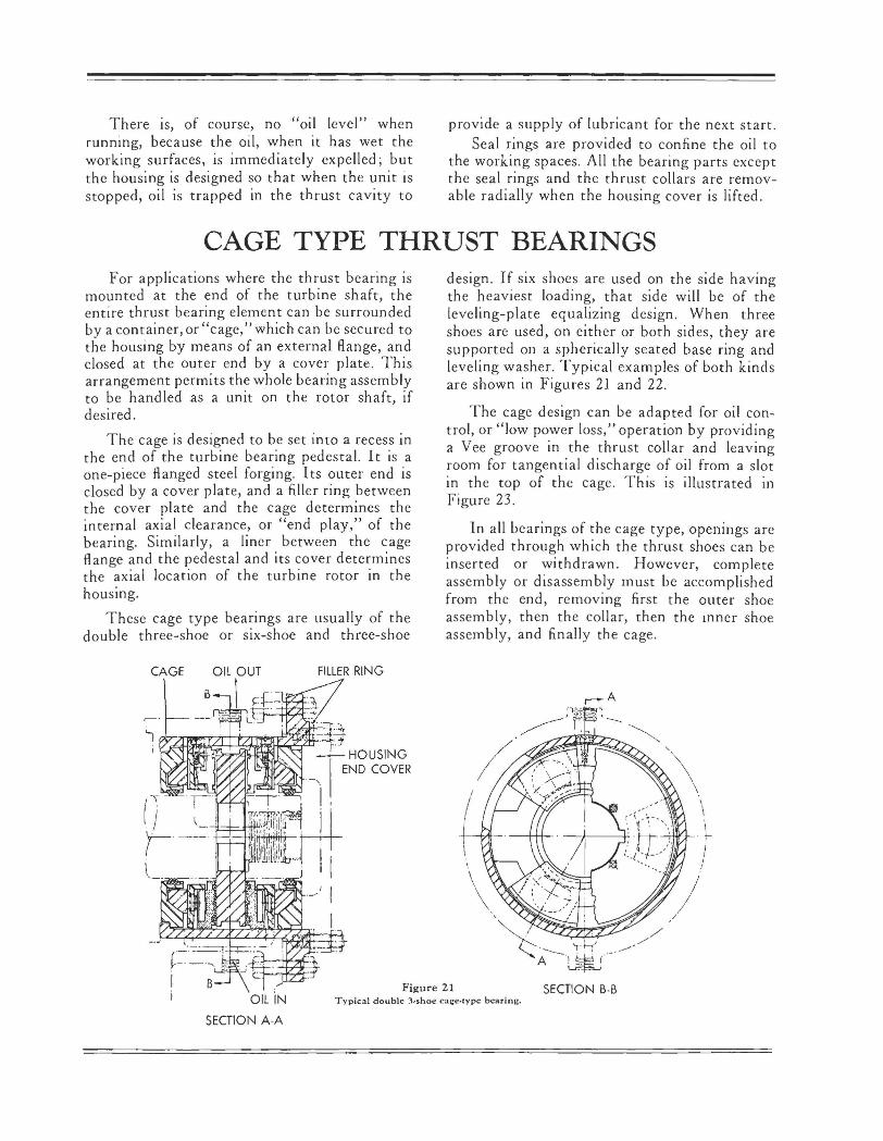
CAGE TYPE THRUST BEARINGS For applications where the thrust bearing is
mounted at the end of the turbine shaft, the entire thrust bearing element can be surrounded by a container, or "cage," which can be secured to the housing by means of an external Range, and closed at the outer end by a cover plate. This arrangement permits the whole bearing assembly to be handled as a unit on the rotor shaft, if desired.
The cage is designed to be set into a recess in the end of the turbine bearing pedestal. It is a one-piece flanged steel forging. Its outer end is closed by a cover plate, and a filler ring between the cover plate and the cage determines the internal axial clearance, or "end play," of the bearing. Similarly, a liner between the cage flange and the pedestal and its cover determines the axial location of the turbine rotor in the housing.
These cage type bearings are usually of the double three-shoe or six-shoe and three-shoe
FILLER RING
design . If six shoes are used on the side having the heaviest loading, that side will be of the leveling-plate equalizing design. When three shoes are used, on either or both sides, they are supported on a spherically seated base ring and leveling washer. Typical examples of both kinds are shown in Figures 21 and 22.
The cage design can be adapted for oil control, or "low power loss," operation by providing a Vee groove in the thrust collar and leaving room for tangential discharge of oil from a slot in the top of the cage. This is illustrated in Figure 23.
In all bearings of the cage type, openings are provided through which the thrust shoes can be inserted or withdrawn. However, complete assembly or disassembly must be accomplished from the end , removing first the outer shoe assembly, then the collar, then the 111ner shoe assembly, and finall y the cage.
Figure 21 SECTION B-B Typical double )~shoe cage•type bearin~.

i,
6 SHOE ELEMENT
OIL IN
B
FILLER RING I HOUSING
fil-~END COVER
I
3 ·SHOE I IELEMENT ;·
I .
I
\ \
'
/ /
""· OIL IN ' ' !
_.LL.J
SECTION A-A
Figure 22
---- -----SECTION B-B
6-shoe and ),shoe cage,type bc~uin,:;. Major thrust is tow.:1rd le(( .
OPENING FOR
--,w;AI SECTION B-B
Figure 23
B
SECTION A-A PART OF COLLAR AND ONE SHOE REMOVED
),sh oe and 6-,;hoe cai::e,typt! bearing arranged for low power Jo.tis at high speed.
,//
"" \
/ /
I
\ '
/
Bulletin
T

ONE-WAY THRUSTS
Figure 24
BASE RING ( IN HALVES)
Diagram of equalizing means for 2,shoe thrust beadngs,
Figure 25 6,shoe one-way rhrusr with separate collar mounted on
shaft end,
BASE RING
LEVELING PLATE
OIL IN
LEVELING 1---.;-+---t;H'1;r All
PLATE
There is a growing field of application of a specialized kind in thrust bearings for blowers and axial compressors, especially in connection with the rapidly expanding gas turbine enterprise. Units of this type are subjected to unidirectional thrusts, and the construction is often of such character that the thrust unit must be assembled endwise in a housing that is not split horizontally.
For such installations, one-way thrust bearings are available in two-shoe, three-shoe and six-shoe arrangements. A typical two-shoe unit is shown in Figure 24 and a six-shoe bearing in Figure 25. Although Figures 24 and 25 indicate collars separate from the shaft, bearings of this type are usually furnished without collar, as the collar is quite often an integral part of the shaft.
While the thrust in these applications is unidirectional and only one set of thrust bearing elements is required, nevertheless it is often necessary to limit the axial "float" of the shaft when running unloaded, and this is generally done by means of a simple "bumper" bearing on the unloaded side of the collar.
OIL OUT

Bulletin
T
VERTICAL TURBINE THRUSTS While the majority of turbine applications
involve the use of a horizontal shaft, there are some pieces of apparatus, notably pump drives and forced-draft blowers, that are frequently arranged with the shaft vertical. Such cases require only a rearrangement of the same basic thrust bearing elements that have been described in connection with horizontally disposed ap pa rat us.
There are three alternative operating conditions that may be encountered in vertical turbine drives. The principal thrust may be downward, with an occasional, lesser, upward reaction under certain operating conditions. On the other hand, the principal thrust may be upward, with minor downward thrust under certain conditions; say, at starting and stopping, etc. The third class is that in which the thrust is downward under all conditions of operation, in which case a single-element unidirectional thrust bearing will answer the requirements.
Bearings suitable for the three classes of service mentioned are illustrated in Figures 26, 27, and 28. The bearing shown in Figure 26 is arranged as a self-contained unit with an oil reservoir provided with a cooling coil to carry away the heat of oil friction. A guide bearing immediately above the thrust bearing is lubricated by employing the runner of the thrust bearing as a pump as indicated in the figure.
Fi11urc 26 6-1hoe And )·'-h.01.· uq:'-·bc-. .rin~ for vcr1ic.1.I unll whl'rc
principal thruu it in downw.ard dir~ccion.
sECnON· A A
Fi~urc 27 Arr,.n~c,ncnt of,. vcrlil'"-~t l ,rcp·bc·.u~n..: for hhch .:pf".cd with
oil conrrol fc .. rurc in di,char"c- from collar rim.
6 SHOE THRUST
ELEMENT r,:--"1,A:;:"111rN~r
Fi~11rc 2B 6-shoc ,1md ],,hoc combln.11ion for vertical unit where n1111Jor
thrU$1 i1 ln upw.i11rd direction.

I JOURNAL BEARING
SHOE I I
OIL LEAK-OFF
OIL OUT
J
The thrust b<'aring has a six-shoe element to take t he principal thrust and a three-shoe element to take thrust in the opposite direction. Figure 28 shows a bearing enclosed in a casing which is complete ly immersed in an oil bath. Oil is admitted to the casing through apertures at top and bottom and is ej ected, by the centrifugal pumping action o f the runne r, through holes in line with t he runner edges, thus ensuring circulation of the oil around the cooling element in the reservoir. In t hi s case also, a six-shoe clement and a t hree-s hoe clement arc used together.
Figure 27 shows a bea ring of the step type hav ing a s ingle six-shoe clement to take a unidirectional thrust. In this case it will be noted that the bearing housing is designed to embody the princip le of t he oi l control ring and thus e nsure minimum powe r loss . In bearings of this ty pe the flow of lubricant must be fully established before the a pparatus is started.
C:J _____ ) SEA RING
Obviously, numerous other combinations and variations arc possible. These examples are shown only to indicate th at practicable bearings can be provided to meet any structura l or operating cond itions that may be imposed by the character of the service intended. Our engineers are ready at all t imes to stud y and discuss special applications.
r-·--.L-- -. ...__ I I
BUMPER BEARING
THRUST COLLAR
It-Ni~ · ,,__~RUST BEARING
OIL TO THRUST
Fii;cur~ 29 6-,1hoe vcnical thru&t wlth bun1pcr he.1rin1: for rcvcnc chru~c ~nd pivorcd-~hoc .:,.de.le be·;n ing,
Bulletin
T
LUBRICATION AND COOLING Although the Kingsbury principle involves
continuous self-renewal of the oil films between shoes and collar, the thickness of those films (and hence the safety of the bearing) depends on the operating conditions. These conditions include load per square inch of shoe area (which can be greater with large shoes than with small ones), and viscosity of the oil at running temperature. Temperature depends on speed and on the cooling means. At high speeds (turbines and blowers) there is also the possibility of power loss due to churning. This is minimized by using the oil control ring, pages 11 and 12.
Though the heating due to oil shear is small, it is a definite quantity which may be calculated. The cooling agent may be an attached external cooler. Or the bearing may be tied into a general lubricating system with central cooling. With vertical bearings, there may be a copper coil in the oil bath, through which cooling water flows.
The "internal" resistance to flow of oil through the bearing assembly itself is slight. The piping and the oil passages in the bearing should be designed to carry the required flow easily. If the oil pump develops high pressure, it may be necessary to restrict the flow to avert needless loss of power. Three to five pounds per square inch at the inlet is usually sufficient.
With oil cooling, the flow must be sufficient to carry off the heat generated by oil shear between shoes and collar. The operating instructions usually specify the viscosity and oil flow recommended. When the correct pressure and restrictions have been established, it is best to have the restrictions take the form of suitable drilled plugs in the oil line at inlet or outlet, or both, so that they cannot be inadvertently changed.
When an oil control ring 1s used, only the inlet is restricted, the outlet being left wholly free. The top discharge is then tangential, like,
that from a centrifugal pump, into a large drain passage.
Horizontal Bearings
Horizontal bearings usually run in sealed cavities through which oil flows and escapes at the top above the thrust collar. The housing must be designed with reference to the entry and discharge of the oil stream. For horizontal shafts the points of entry (on each side of the collar) are usually in the lower housing, and are so placed as to lead directly to oil passages in the six-shoe base ring or three-shoe leveling washer.
Vertical Bearings
Most vertical bearings run in a bath of oil, which is kept from the shaft by a fixed oilretaining tube secured to the housing at its base with an oil-tight joint. The tube rises above the highest level of the oil in the bath. The runner is bored to clear the tube by a space sufficient to avoid objectionable oil foaming at the intended speed.
Where only downward loads and ordinary speeds are expected (such as in pumps and generators), very simple arrangements are sufficient. For such bearings, in medium to large sizes, the usual cooling means is a water coil submerged in a large oil pot surrounding the bearing. Baffies should be used to ensure oil movement across the coil. An alternative is to circulate the oil in and out, and cool it outside, where any leak in the cooler can more readily be seen and repaired. Where the oil is to be cooled outside the housing, the required flow is specified in the instructions which accompany each order.
For high-speed vertical bearings (as for vertical turbine-driven auxiliaries on shipboard), arrangements similar to the oil control ring should be worked out. As they are somewhat special, we should be consulted.

Symbols for Standardized Designs Kingsbury Thrust Bearings are built in a
great variety of types and sizes. They may be regarded as a unique system of clements built around moving films of oil, rather than as specific articles of manufacture. Certain standardized
components are used in various groupings, with lubrication and housing to suit.
Designs, past or present, sufficiently established to carry symbols are here listed. Current standards should be used wherever possible.
Bearing Symbol
(See Note)
JHJ JH
JJ J
BHB BH BB B
JHN
JN
BHN
BN
NHN NH NN N
Equalizing Types, Horizontal and Vertical Elements Only
NoTE; "H" as part of symbol means that separate collar is furnished by us. "6" or" 3" means shoes on one side only of collar. "6 x 6," etc., means shoes on both sides. "J" and "B" base rings are usually split: "N" base rings are always solid.
Horiz. No. of Usual Description or Vert. Shoes Size
Shaft (See Note) Range
H 6x6 5-17 m:a JHJ
H 6 5-17 ~:1 JH
H 6x6 5-17 ;1 JI •·
~ H 6 5-17 J • H 6x6 5-45
mo '
JHJ Elements
H 6 5-45 B base is same as for J series
H 6x6 5-45 except thinner.
H 6 5-45
H 6x3 5-17 m m • JHN
H 6 X 3 5-17 il JN • H 6 X 3 5-17 B base is same as for J series
except thinner. JHN Elements
H 6 X 3 5-17
H 3 X 3 5-17 m NHN
E • ~l H 3 5-17 NH
H 3 X 3 5-17 t~ NN ' * N
NHN Elements H 3 5-17 (Compare JHN)

Bulletin
T
Symbols for Standardized Designs Equalizing Types, Elements Only
(continued)
Bcar!nf Hori.z. No. of Usual Description Symbo or Vert. Shoes Size
(Sec Nou) Shaft (Sec Note) Range
KV V 6 5-17 m KV
LV V 3 5-17 LV i11·;tl
JV V 6 5-17 $ JV e JV Elements
BV V 6 5-17 13V is like JV but thinner base ring.
NV V 3 5-17 -=-~ NV
KBV V 6 19-45 ~ KBV
IOO,OCO.kw, .J600,.cpm tandem compound rchc.iit "°Cc.1m turbine inJt.11ticd ln Minnesota. Stc .. m condJ,lon,~ 1450 pt~IC lOfXJ/ 1000° P. I VJ- Jobi. e~h ... u.-:c prcuurc,
P~oto. courL<:"-y All" Chalmers. Milwaukee. W,s
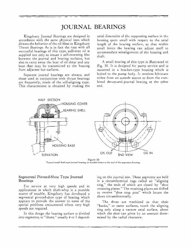
JOURNAL BEARINGS Kingsbury Journal Bearings are designed in
accordance with the same physical laws which dictate the behavior of the oil films in Kingsbury Thrust Bearings. As is in fact the case with all successful bearings of this type, sufficient oil is supplied not only to insure a self-renewing film between the journal and bearing surfaces, but also to carry away the heat of oil shear and any heat that may be transmitted to the bearing from adjacent hot surfaces.
Separate journal bearings are always, and those used in conjunction with thrust bearings are frequently, made of the self-aligning type. This characteristic is obtained by making the
HALF SECTION HOUSING COVER
HOUSING BASE
ELEVATION
axial dimension of the supporting surface in the housing qmte small with respect to the axial length of the bearing surface, so that within small limits the bearing can adjust itself to accommodate misalignment of the housing and shaft.
A small bearing of this type is illustrated in Fig. 30. It is designed for pump service and is mounted in a bracket-type housing which is bolted to the pump body. It receives lubricant either from an outside source or from the combined thrust-and-journal bearing at the other end.
OIL OUT END VIEW
OIL IN
Figure 30 Typical small shell-type journal bearing in bracket bolted to the end of th~ apparatus housing.
Segmental Pivoted-Shoe Type Journal Bearings
For service at very high speeds and in applications in which shaft-whip is a possible source of trouble, Kingsbury has developed a segmental pivoted-shoe type of bearing which appears to provide the answer to some of the special problems encountered where very high speeds are required.
In this design the bearing surface is divided into segments, or "shoes," usually 4 or 5 depend-
ing on the journal size. These segments are held in a circumferential cage called an "aligning ring," the ends of which are closed by "shoe retaining plates." The retaining plates are drilled to receive "shoe stop pins" which locate the shoes circumferentially.
The shoes are machined so that their "backs," or outer surfaces, touch the aligning ring only along a narrow axial surface, about which the shoe can pivot by an amount determined by the radial clearance.

OIL OUT
\
\
An ample supply of oil is fed into the spaces between the shoes and as soon as rotation starts a film of oil is drawn in between the journal and each of the shoes, the film being thicker at the entering edge. Thus is established the automatically se lf-renewing "wedge-shaped film of oil" between each shoe and the journal, which is the distinguishing characteristic of Kingsbury bearing design.
Since the shoes are equally spaced around the journal, and each has between it and the journal a supporting and cushioning film of oil,
Fii:urc J2 L~rc:er bc-~rinJ: of thC' pivoted•
"h<'r 1ypc wlth fiv~ thocs.
A
' I ;-~ ~~~---,----~
B
Bulletin
T
Fii:urc ) 1 J<'urn.11 bearin::; of 1he- pivoted•
1.hoC' tV~ wi1h four 1.hcw:1.,
it can readily be seen that this arrangement is highly effective in damping out any tendency toward whip or vi brat ion.
These bearings are used both as separate journal bearings and in combination with a suitable type of Kingsbury Thrust Bearing, and in vertical as well as horizontal applications. Figures 31 and 32 show typical separate journal bearing examples, whil e Figure 29 shows a vertical unidirectional equa lizing thrust bearing with a pivoted-shoe jou rnal bea ring.
B_
SECTION A A

SPARE PARTS A Kingsbury Bearing correctly chosen, prop
erly aligned and supplied with clean oil, is practically indestructible for the life of the ship. However, spare parts are customarily provided as a matter of insurance.
For marine machinery, American Bureau of Shipping rules will usually determine what spare parts are required. These regularly include thrust
shoes, occasionally thrust collars, also journal bearing shells and cooler parts where fitted.
For other applications, it is usually sufficient to stock thrust shoes, and thrust collars or runners.
The other parts of the bearing practically never need replacement. Therefore, there is no need to carry complete bearings as spares.
DATA NEEDED WITH INQUIRIES In order that we may be able to cooperate
intelligently in the selection of the proper Kingsbury bearing for a new application, we should receive full information regarding the expected conditions of operation.
Specifically, we should have at least the answers to the following:
(A) Is shaft horizontal or vertical?
(B) What are thrust loads, normal and maximum?
(C) What reverse thrust is expected, if any?
(0) What are the rpm, normal and maximum?
(E) What is shaft diameter m way of bearing?
(F) Will thrust collar be integral with shaft or separate?
(G) Are solid or split base rings desired (6 or 8 shoe only)?
(H) What are characteristics of lubricant to be supplied and what is expected inlet temperature?
(J) What is Journal bearing load (when applicable)?
In addition, the kind of service should be stated, the general arrangement of the machine should be sketched or described, and any pertinent space limitations indicated.
STANDARD GUARANTEE Any bearing or part furnished by us, which
shall prove defective in design, material or workmanship within one year after installation and test, will be replaced without charge f.o.b. Philadelphia, if returned to our factory. This period is, however, limited to a maximum of two years from the date of shipment from the fac-
tory. No allowance will be made for labor or other expense in connection therewith unless authorized in writing by an officer of the Company.
For oil coolers and cooling coils, in accordance with usual trade practice, there is no specific guarantee period.
PRESS OF S. H. BUPU!ANK & CO., INC.
PHILADELPHIA, PA .

,
•