Embed Size (px)
Citation preview

sepr
o

Contents
Suckers and nozzles P.24
Grabbers and grabberfingers P.28
Support flanges P.22
Sprue cutters P.34
Structures, profiles,tubes... P.10
Pneumatic and electrical connections
P.8
Base plates formounting on robotand base plate holders
P.4
and to assemble your grippers :
◆ Screws and fixings . . . . . . . . . . . . . . . . . . . . P.38
◆ Assembly recommendations . . . . . . . . P.38
◆ Pneumatic fittings . . . . . . . . . . . . . . . . . . . . . . P.40
3

4
Base plates
locating device
BP 90
233 g
Roll pin 3x25
484 g
Roll pin 3x25
locating device
BP 120

Base plates
5
677 g
CHC M6 x 16
CHC M6 x 16
locating device
BP 135
BP 146
764 g
locating device

6
Base plates holders
BPH 1
395 g
BPH 2
742 g

Base plates
7
RBP 150
294 g
521 g
1.4 kg
RBP 200
RBP 300

8
Pneumatic and electrical connections
For Range 3000
PP 01
PP 02
PP 03
PP 04
PP 05
PP 06
PP 07
PP 11
PP 12
PP 13
PP 14
PP 15
✗
✗
Pipe ø in mm (*) code
4
6
In packs of : 1 10
SP 4
SP 6
EPF 1 EPM 1
◆ 8 port connection block complete with plugs, with locating device
◆ 2 port connection block
◆ Stopper
PP 42
PP 62
code
position 2
position 1
position 0
EPF 1
EPM 1Pipe ø in mm (*) position 0 position 1 position 2
4 4 4 4
4 4 4 6
4 4 6 6
4 6 6 6
6 6 6 6
- 4 4 4
- - 4 4
PP 21
PP 22
PP 23
PP 24
PP 25
✗
✗
(*) pipe ø = external pipe ø

Pneumatic and electrical connections
9
◆ Locating device
Connection number
Pipe ø (*)in mm
Male code
6 4 4 4 6 4 4 4
6 6 4 4 6 6 4 4
6 6 6 4 6 6 6 4
6 6 6 6 6 6 6 6
MP 1
MP 2
MP 3
MP 4
EPM 1
EPM 2
5 mm allen key
Location pin position
(*) pipe ø = external pipe ø ◆ 8 port connection block complete with plugs, with locating device
1 2 3 4 5 6 7 8
9

10
6x6 tube and accessories
T 6
LT6 C
LT6 D
L weight
1 m 91 g/m
LT6 F
for grabber weight
ø 20 8 g
ø A weight
6 7 g
8.5 7 g
LT6 A
LT6 B
LT6 E
11 g
ø A weight
6 11 g
8.5 10 g

Accessories for 6x6 tube
11
LT6 G
for grabber weight
ø 20 13 g
ø A weight
6 17 g
8.5 16 g
L2T6 B
L2T6 C
8 g
L2T6 A
L2T6 D
23 g

12
ø12 tube and accessories
LT12 B
LT12 C
LT12 D
LT12 A
ø A weight
6 39 g
8.5 38 g
10.5 37 g
12.5 36 g
LT12 F
LT12 G
LT12 H
LT12 E
L weight
1 m 255 g/m
L2T12 A
73 g
LT12 I
32 g
T 12
ø A weight
6 24 g
8.5 23 g
10.5 22 g
12.5 21 g
ST 12
In packs of 10

13
Accessories for ø12 tube
for grabber weight
ø 20 38 g
ø 25 37 g
LT12 J
LT12 K
for grabber weight
ø 20 22 g
ø 25 21 g
LT12 L
LT12 M
14
Accessories for ø12 tube
26 g 27 g
L2T12 C L2T12 D
21 g
L1T12
L2T12 B
16 g
M5 nuts locate internally
2 holes M5 x 16,5 to be drilled for
assembly in this way + 2 x C 20 Assembly with 2 x
+ 2 x
C 16
NUT 4
Assembly with 1 x
+ 1 x
C 20
NUT 4
Assembly with 2 x
+ 2 x
C 40
NUT 4
◆ Recommendations for correct assembly
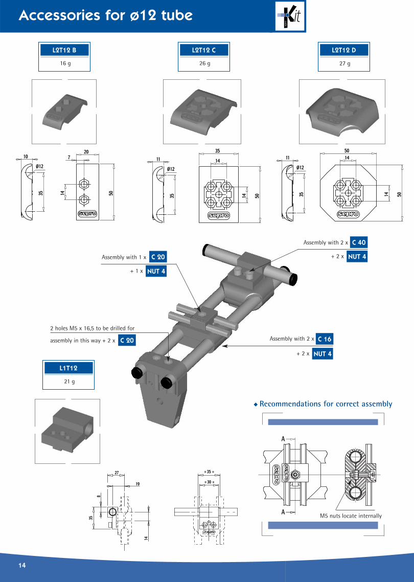
Accessories for ø12 tube
15
44 g
L2T12 E
37 g
L2T12 F
69 g
L2T12 G
Assembly with 2 x
+ 2 x
C 16
NUT 4
Assembly with 2 x
+ 2 x
C 16
NUT 4
Assembly with 1 x
+ 1 x
C 16
NUT 4
Assembly with 2 x
+ 2 x
C 20
NUT 4
Assembly with 2 x
+ 2 x
C 20
NUT 4
16
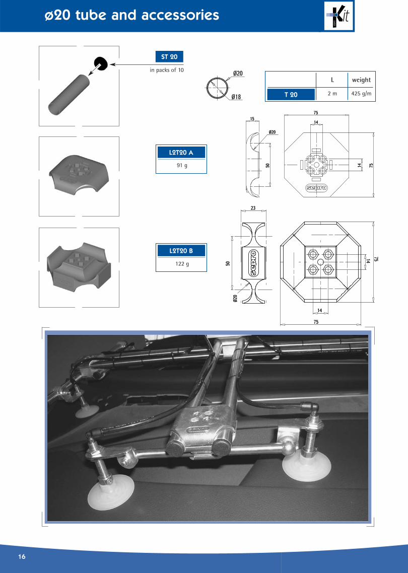
ø20 tube and accessories
91 g
L2T20 A
L weight
2 m 425 g/mT 20
in packs of 10
ST 20
122 g
L2T20 B

Accessories for ø20 tube
17
LT20
92 g
LT12 20
125 g
L2T20
150 g

18
Accessories for ø20 tube
◆ Recommendations for correct assembly
LT12 20 B
143 g
2 x M5 screws
M5 Nuts locate internally
Assembly with 2 x
+ 2 x
C 30
NUT 4
Assembly with 2 x
+ 2 x
C 16
NUT 4
Assembly with 2 x
+ 2 x
C 30
NUT 4
Assembly with 2 x
+ 2 x
C 25
NUT 4
LT12 20 A
100 g

Accessories for ø20 tube
19
L1T12
21 g
L1T20
35 g
◆ Recommendations for correct assembly
2 x M5 screws
M5 Nuts locate internally
Assembly with 2 x
+ 2 x
C 40
NUT 4
Assembly with 2 x
+ 2 x
C 40
NUT 4
Assembly with 2 x C 40
Assembly with 2 x C 40
Assembly
with 2 x + 2 x C 25 NUT 4
20
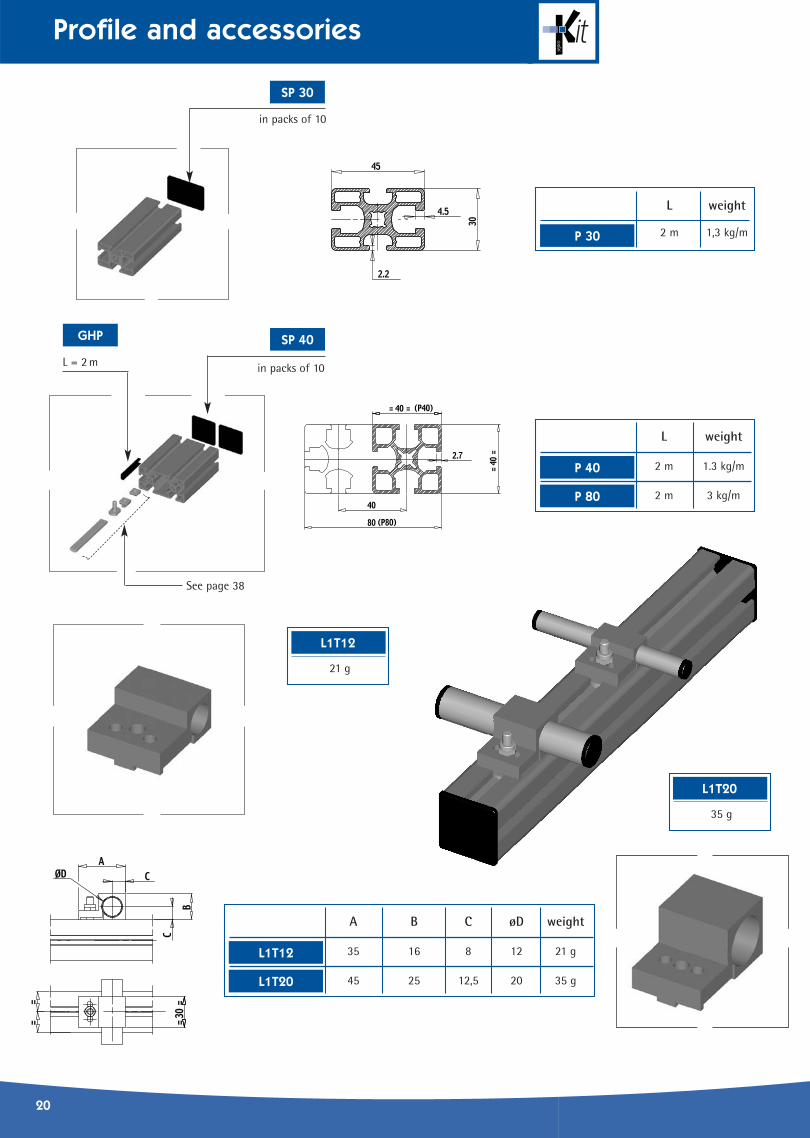
Profile and accessories
L weight
2 m 1,3 kg/mP 30
L weight
2 m 1.3 kg/m
2 m 3 kg/m
P 40
P 80
A B C øD weight
35 16 8 12 21 g
45 25 12,5 20 35 g
L1T12
L1T20
SP 30
SP 40GHP
See page 38
L = 2 m
in packs of 10
in packs of 10
L1T12
21 g
L1T20
35 g

Profile and accessories
21
F G H J weight
26 14 16 3 25 g
36 19 23 4 65 g
LP 26
K L M N P R weight
80 100 24 44 95 127 82 g
100 120 44 64 116 145 106 g
LP 100
LP 120
43 g
LP 12
LP 36
LP 12+ L2T12C
LP 26/36
LP 100/120

22
Support flanges
SG 20 L
SG 25 L
ø F weight
20 81 g
25 76 g
SG 20
SG 25
B B1 C C1 D for grabber weight
22.5 13 65 40 20 ø 20 36 g
25 16 77 52 25 ø 25 66 g
2 holes M5 x 16.5 to be drilled to assemble in this orientation with 2 x
C 20
NUT 4
Assembly with 2 x
C 20
+ 2 x

Support flanges
23
ø E F weight
8 22 20° 13 g
10 22 20° 12 g
12 22 20° 11 g
20 22 20° 6 g
25 16 10° 2 g
BL 8
BL 10
BL 12
BL 20
BL 25
ø G weight
8.2 91 g
10.2 90 g
12.2 89 g
SV 8
SV 10
SV 12
65 g
SBL
Required orientation
for ball
2 holes M5x16.5 to be drilled
to assemble in this orientation with 2 x
Please align slots
for efficient tightening
C 20

24
Suckers
ø (mm) Nozzle end Silicon Nitrile H* H1**
10 4
15 4
20 4
25 4
26 8
35 8
52 8
60 8
75 12
95 12
5.5 4
11 4
16 4
19 4
25 4
26 8
33 8
53 8
63 8
6 4
7 4
9 4
12 4
14 4
18 4
25 4
26 8
42 8
62 8
VD 25 S
VD 26 S
VD 33 S
VD 53 S
VD 63 S
VT 6 S
VT 7 S
VS 10 S
VS 15 S
VS 20 S
VS 25 S
VS 26 S
VS 35 S
VS 52 S
VS 60 S
VS 75 S
VS 95 S
VD 5 S
VD 11 S
VD 16 S
VD 19 S
VT 9 S
VT 12 S
VT 14 S
VT 18 S
VT 25 S
VT 26 S
VT 42 S
VT 62 S
VD 25 N
VD 26 N
VD 33 N
VD 53 N
VD 63 S
VT 6 N
VT 7 N
VS 10 N
VS 15 N
VS 20 N
VS 25 N
VS 26 N
VS 35 N
VS 52 N
VS 60 N
VS 75 N
VS 95 N
VD 5 N
VD 11 N
VD 16 N
VD 19 N
VT 9 N
VT 12 N
VT 14 N
VT 18 N
VT 25 N
VT 26 N
VT 42 N
VT 62 N
* Height without load ** Height with load
VS 60 S
VS 75 S
VS 95 S
VD 5 S
VD 11 S
VD 16 S
VD 19 S
10,5
11
11,5
12
19,5
20
22
22
32
38
11
16
19
16
23
24,5
27,5
34
34
13,2
14
15
21
23
23
34
33
46
55
9
8,75
8,5
9
17
17
17,5
17,5
27,5
26
9
10,5
10,5
11
11
18,5
16,5
19
19
10,2
10
12
14
13
13
14
21
24
24
VD 25 N
VD 26 N
VD 33 N
VD 53 N
VD 63 N
VT 6 N
VT 7 N
VT 9 N
VT 12 N
VT 14 N
VT 18 N
VT 25 N
VT 26 N
VT 42 N
VT 62 N
Suckers
25
* Height without load ** Height with load
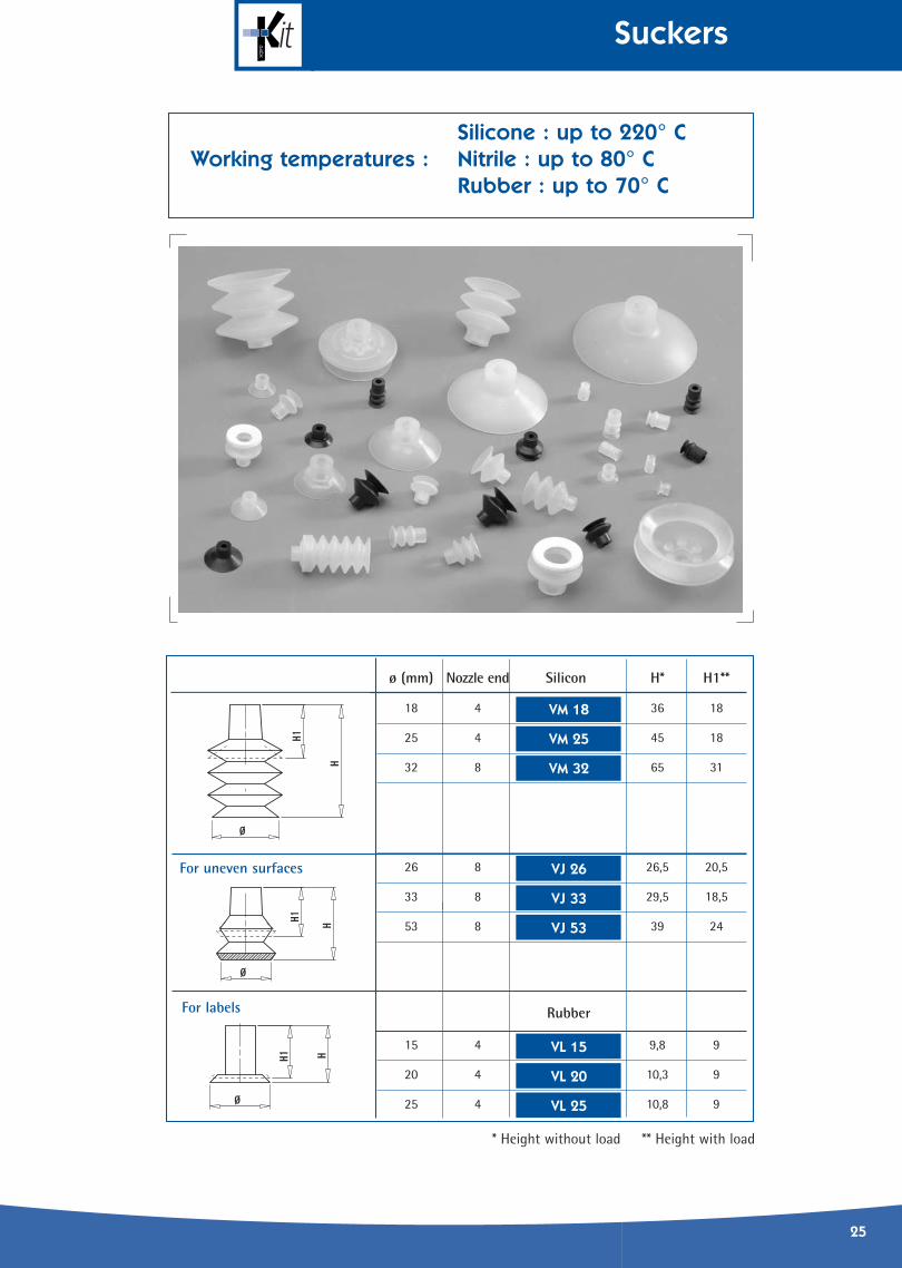
ø (mm) Nozzle end Silicon H* H1**
18 4 4Í 36 18
25 4 45 18
32 8 65 31
26 8 26,5 20,5
33 8 29,5 18,5
53 8 39 24
15 4 9,8 9
20 4 10,3 9
25 4 10,8 9
VM 18
VM 25
VM 32
VJ 26
VJ 33
VJ 53
VL 15
VL 20
VL 25
Rubber
For uneven surfaces
For labels
Silicone : up to 220° CNitrile : up to 80° CRubber : up to 70° C
Working temperatures :

26
Nozzles
A M8x1 M8x1 M10x1 M10x1 M12x1,25 M12x1,25
B 33 43 38,5 53,5 48,5 68,5
Weight 18 g 21 g 48 g 56 g 75 g 91 g
Nozzle end 4 4 8 8 12 12
Complete with one M5 plug
FN 4 C FN 4 D FN 8 A FN 8 B FN 12 A FN 12 B
2 g
FN 4 A
9 g
FN 4 B
Assembly example
Pneumatic connection
Pneumaticconnection
Pneumatic fittings To be ordered separately. See page 40.

Nozzles
27
RS 12
Proximity sensor
Pneumaticconnection
Pneumaticconnection
Complete set with sensor
F M8 x 1 M10 x 1 M12 x1,25
G 64,5 64,5 70,5
G1 45 45 50
G2 3 3 4
Weight 30 g 60 g 85 g
4 8 12
Spring tension
Soft Soft Hard
SN 4 SN 8 SN 12
Nozzle end
Weight 88 g 108 g
4 8
Spring tension
Soft Hard
SN 4 L SN 8 L
Nozzle end
Weight 160 g 180 g
4 8
Spring tension
Soft Hard
DU 4 DU 8
Nozzle end

28
Grabbers
S S1 S2 S3 T T1 T2
ø 20 grabber 47 4 14,5 26 9 12 17
ø 25 grabber 60 6,5 19,5 31,5 11 14 19
Force at A :6 bars
40 N
56 N
B B1 B2 C C1 D
ø 20 grabber 69 20 32 34 39 15
ø 25 grabber 91 27 38 40 46 28
ø 20 grabber 76 g 72 g 90 g
ø 25 grabber 139 g 134 g 155 g
GS 20
GS 25GR 25
GR 20
G 25
G 20
SPG 25
SPG 20ø 20 grabber
ø 25 grabber
without detection with detection
weight
3 g
5 g
Grabbers
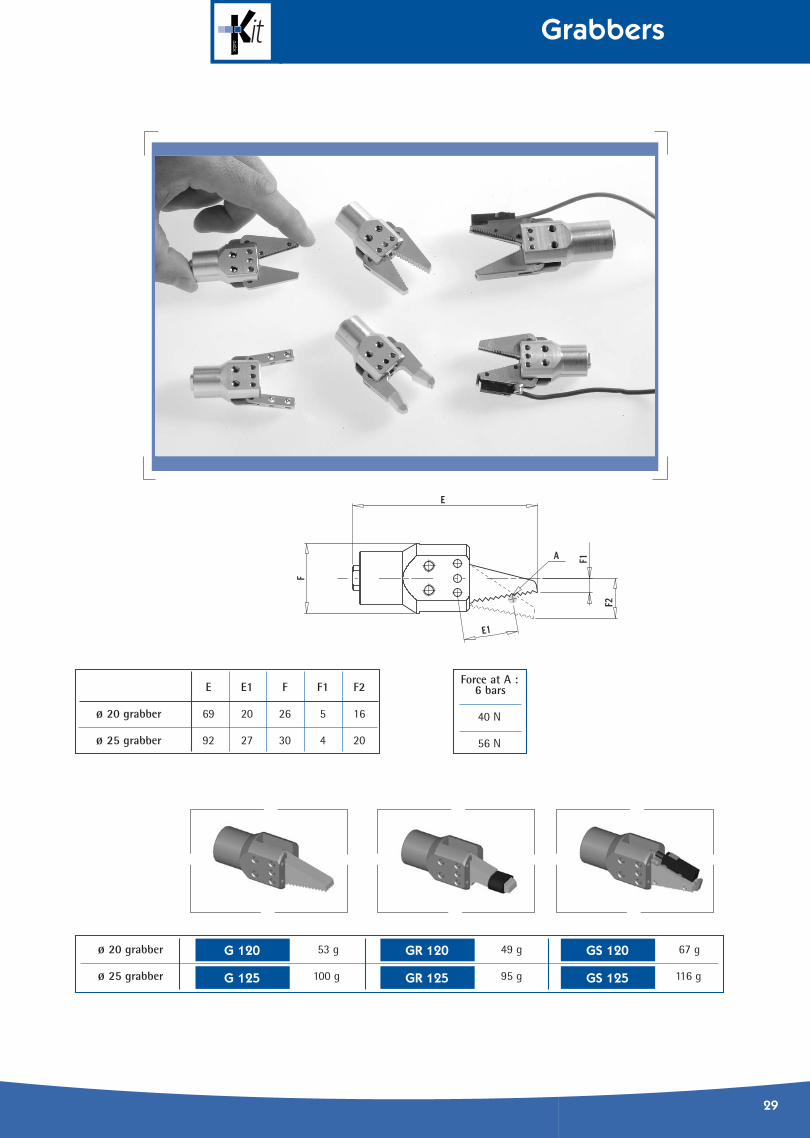
29
Force at A :6 bars
40 N
56 N
E E1 F F1 F2
ø 20 grabber 69 20 26 5 16
ø 25 grabber 92 27 30 4 20
ø 20 grabber 53 g 49 g 67 g
ø 25 grabber 100 g 95 g 116 g
GS 120
GS 125GR 125
GR 120
G 125
G 120

30
Grabbers
N N1 P P1 P2 R
ø 20 grabber 63 21,5 18 7,5 5 11,5°
ø 25 grabber 80 26 22 8,5 6 14° GV 25
GV 20ø 20 grabber 60 g
ø 25 grabber 108 g
In packs of 10
RRGRSG◆ Replacement parts
Nozzles accessories to be ordered separately.
FN 4B

Grabbers
31
H H1 H2 J J1 J2 J3 K K1 K2 K3 K4 K5 K6 L L1 M
ø 20 grabber 60 53 20 34 50 18 26 14 21 3 8 6 12 15 7° 12° M3
ø 25 grabber 78,5 72 27 44 64 20 31 18 25 4 10 7 14,5 19,5 12° 20° M4
U U1 U2 U3 V V1 W1 Y
ø 20 grabber 43,5 39 28,5 16 ø 20 9 8 M4
ø 25 grabber 59 53,5 39,5 26 ø 25 11 10 M5
Force at A
40 N
56 N
ø 20 grabber 56 g 56 g
ø 25 grabber 100 g 6 g 105 gGJ 25 A
GJ 20 A
GJ 25
GJ 20
Identical dimensions for all types of grabbersScrews
supplied

32
Grabber fingers
GF 90
200 g
GF 30
190 g

Accessories for grabber fingers
33
LGFE
42 g
SGFE
17 g
JGFL
40 g
JAW
Screw supplied

34
Sprue cutters
L weight Force at A
L1= 203 2,3kg 800 daN
L2 = 148 1,6 kg 280 daN
GK 60 A
GK 60 B
70 g
SB 60 L
200 g
FF 60
84 g
IB 60 L
◆ Straight cutting blades (hardened steel)
◆ Inclined cutting blades(hardened steel)
Screws supplied
Set of blades only(hardened steel)
Cutting edge
Body (without blades)

Sprue cutters
35
330 g
CKI 40 A
330 g
CKS 40 A
135 g
FF 40
67 g
FA 40
330 g
CKS 40 B
330 g
CKI 40 BSet of blades only(hardened steel)
Cutting edgeBody completewith 1 set of blades
Body completewith 1 set of blades
IB 40
Set of blades only(hardened steel)
SB 40
Maximum force :6 bar at point A= 200 daN

36
Sprue cutters
700 g
CKI 60 A
700 g
CKS 60 A
700 g
CKS 60 B
700 g
CKI 60 B
Set of blades only(hardened steel)
Body completewith 1 set of blades
Body completewith 1 set of blades
IB 60 S
Set of blades only(hardened steel)
SB 60 S
Maximum force :6 bar at point A= 350 daN
Cutting edge
Cutting edge

Sprue cutters
37
700 g
CKQ 60 A
700 g
CKQ 60 BSet of blades only(hardened steel)
Body completewith 1 set of blades
Body completewith 1 set of blades
QB 60 S
Maximum force :6 bar at point A= 280 daN
200 g
FF 60
Cutting edge

38
Screws and fixings
Assembly recommendations
◆ Recommended methods for fixing
M6 M6 M5 M6 M5
In packs of x1 x20 x50 x20 x50
L = 12 - B12 C12 D12 E12
L = 16 A16 B16 C16 - E16
L = 20 A20 B20 C20 - E20
L = 25 - - C25 - E25
L = 30 - - C30 - E30
L = 40 - - C40 - E40
NUT1 NUT2 NUT3 NUT4 WASH1 WASH2 PBAR
M6 M6 M6 M5 Ø6 Ø6 L = 90 mm
A16
NUT1 NUT2 NUT3 NUT4 WASH1 WASH2 PBAR
A20
A25
B16
B12
B20
C16
C12 D12
C20
C25
C30
C40
E16
E12
E20
E25
E30
E40
x50 x20 x50 x50 x50 x50 x1

Assembly recommendations
39
◆ Assembly methods : profile + base plate + gripper plate
◆ Assembly methods : profile + base plate + gripper plate
◆ Assembly methods : profile + base plate

40
Pneumatic fittings
Semi-rigidpolyamidepipe Ø4
black
red
blue
black
red
blue
black
grey
red
blue
black
grey
red
blue
Semi-rigidpolyamidepipe Ø6
Flexible polyurethane
pipe Ø6
Flexible polyurethane
pipe Ø4L = 5 m
Connection size
In packs of
Connection size
In packs of
Connection size
In packs of
Connection size
In packs of
Connection size
In packs of
Connection size
SP 4
RQ 44
RT4BK
RT4RD
RT4BL
RT6BK
RT6RD
RT6BL
FT4BK
FT4GY
FT4RD
FT4BL
FT6BK
FT6GY
FT6RD
FT6BL
SP 6 MP 64 RP 44 RP 66
PM 54 PM 56 RM 54 RM 56 QM 54 QM 56 Q 186
ø 4-
ø 6-
M5ø 4
M5ø 6
M5ø 4
M5ø 6
TP 44 TP 66 CROS 44 CROS 66
ø 4ø 4
ø 6ø 6
ø 4ø 4
ø 6ø 6
M5ø 4
M5ø 6
1/8ø 6
ø 4ø 4
ø 6ø 6
ø 6ø 4
ø 4ø 4
SM 5
M5
RQM 54 RQM 56 RQ 186
M5ø 4
M5ø 6
1/8ø 6
DP 44 DP 64 DP 66
ø 4ø 4
ø 6ø 4
ø 6ø 6
QP 44 QP 64 QP 66
ø 4ø 4
ø 6ø 4
ø 6ø 6
EP 44 EP 46 EP 66
ø 4ø 4
ø 4ø 6
ø 6ø 6
x 10 x 10
x 10 x 10
x 1 x 1 x 1 x 1
x 10 x 10 x 10 x 10 x 1
x 10 x 10 x 1
x 1 x 1 x 1 x 1 x 1 x 1 x 10 x 10 x 10
x 10 x 10
x 1 x 1 x 1
Connection ø = external connection ø Pipe ø = external pipe ø