Embed Size (px)
Citation preview
REV.
1/2
5/20
17
INST
95-7
631B
INSTALLATION INSTRUCTIONS FOR PART 95-7631B
METRA – The World’s best kits.® metraonline.com © COPYRIGHT 2017 METRA ELECTRONICS CORPORATION
CAUTION! All accessories, switches, climate controls panels, and especially air bag indicator lights must be connected before cycling the ignition. Also, do not remove the factory radio with the key in the on position, or while the vehicle is running.
• ISO DDIN radio provision• Painted matte black
• A) Radio trim panel • B) Radio brackets • C) (4) #8 x 3/8” Phillips screws
KIT FEATURES
KIT COMPONENTS
WIRING & ANTENNA CONNECTIONS (sold separately)Wiring Harness: • 70-7552 Antenna Adapter: • 40-NI12
• Panel removal tool • Phillips screwdriver • 12mm socket wrench • T-20 Torx driver
TOOLS REQUIRED
Nissan Titan 2017-up, Titan XD 2016-up95-7631B
Table of Contents
A B C
Dash Disassembly ..............................................2-5
Kit Assembly .......................................................... 6
95-7631B
2
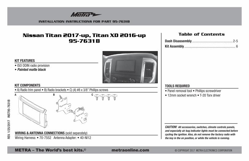
Dash Disassembly
1. Remove the (2) Phillips screws securing the knee bolster panel below the steering column, and then unclip the panel. It is not necessary to completely remove the panel. (Figure A)
2. Unclip and remove the passenger door sill and kick panel. (Figure B)
3. Remove the (5) T-20 Torx screws securing the glove box and then remove. There are (2) screws below the glove box, and (3) screws exposed when you open the glove box. (Figures C and D)
Continued on next page
(Figure B)
(Figure D)
(Figure A) (Figure C)
Upper screws
Lower screws

95-7631B
3
Dash Disassembly
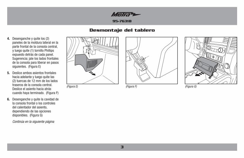
4. Unclip and remove the (2) side trim panels at the front of the center console, and then remove the (1) Phillips screw exposed behind each panel. Tip: Pull out on the front sides of the console to release for later steps. (Figure E)
5. Slide both of the front seats forward and then remove the (2) 12mm bolts from the rear sides of the center console. Slide the seat back once done. (Figure F)
6. Unclip and remove either the front console pocket or heated seat controls, depending on options available. (Figure G)
Continued on next page
(Figure F)(Figure E) (Figure G)

95-7631B
4
Dash Disassembly
7. Unclip and remove the trim panel where the center console and the dashboard meet, and then remove the (2) Phillips screws exposed. (Figure H)
8. Slide the center console back, and then unclip and remove the vent panels from each side of the radio/climate control panel. (Figure I)
9. Remove the (2) Phillips screws securing the accessory panel below the climate control panel, and then unclip and remove. (Figure J)
Continued on next page
(Figure J)(Figure I)(Figure H)
95-7631B
5
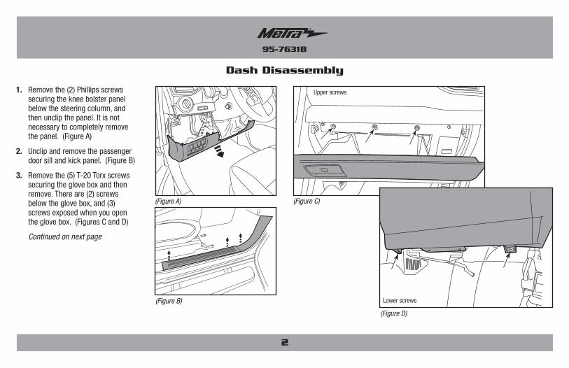
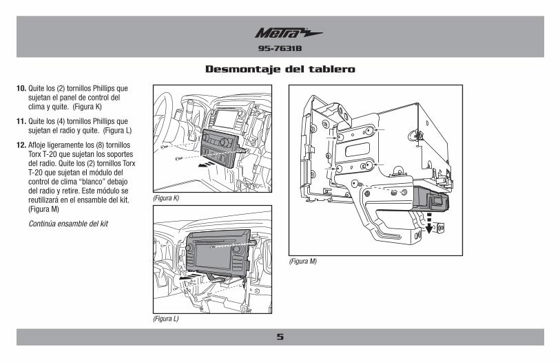
10. Remove the (2) Phillips screws securing the climate control panel and then remove. (Figure K)
11. Remove the (4) Phillips screws securing the radio and then remove. (Figure L)
12. Slightly loosen the (8) T-20 Torx screws securing the radio brackets. Remove the (2) T-20 Torx screws securing the “white” climate control module below the radio and then remove. This module will be reused in kit assembly. (Figure M)
Continue to kit assembly
Dash Disassembly
(Figure M)
(Figure L)
(Figure K)
95-7631B
6
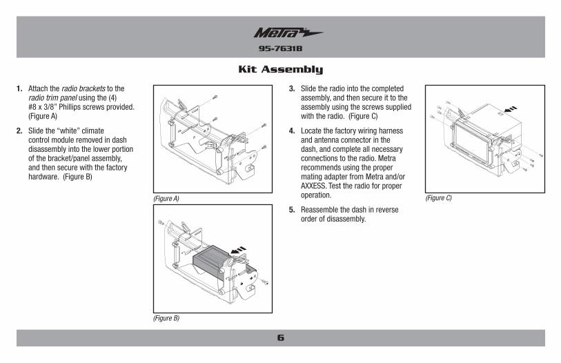
Kit Assembly
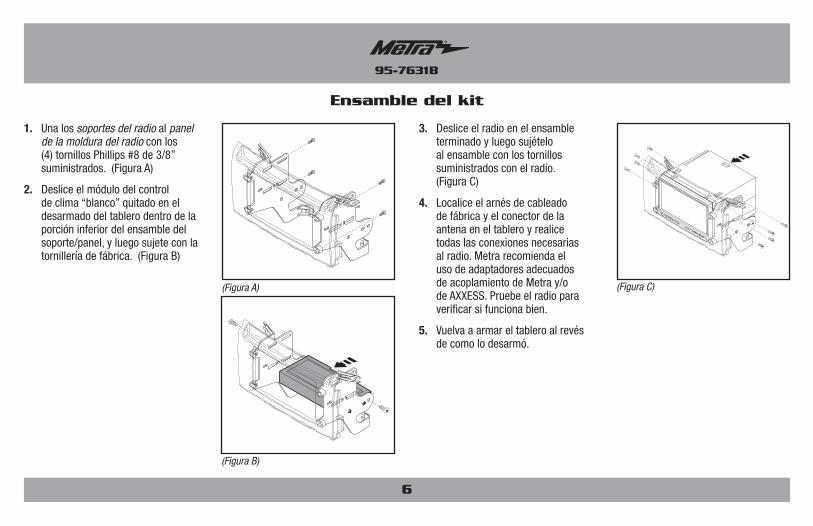
1. Attach the radio brackets to the radio trim panel using the (4) #8 x 3/8” Phillips screws provided. (Figure A)
2. Slide the “white” climate control module removed in dash disassembly into the lower portion of the bracket/panel assembly, and then secure with the factory hardware. (Figure B)
3. Slide the radio into the completed assembly, and then secure it to the assembly using the screws supplied with the radio. (Figure C)
4. Locate the factory wiring harness and antenna connector in the dash, and complete all necessary connections to the radio. Metra recommends using the proper mating adapter from Metra and/or AXXESS. Test the radio for proper operation.
5. Reassemble the dash in reverse order of disassembly.
(Figure C)
(Figure B)
(Figure A)

95-7631B
7

REV.
1/2
5/20
17
INST
95-7
631B
INSTALLATION INSTRUCTIONS FOR PART 95-7631B
KNOWLEDGE IS POWEREnhance your installation and fabrication skills by enrolling in the most recognized and respected mobile electronics school in our industry.Log onto www.installerinstitute.com or call 800-354-6782 for more information and take steps toward a better tomorrow.
Metra recommends MECP certified technicians
IMPORTANTIf you are having difficulties with the installation of this product, please call our Tech Support line at 1-800-253-TECH. Before doing so, look over the instructions a second time, and make sure the installation was performed exactly as the instructions are stated. Please have the vehicle apart and ready to perform troubleshooting steps before calling.
METRA – The World’s best kits.® metraonline.com © COPYRIGHT 2017 METRA ELECTRONICS CORPORATION

INSTRUCCIONES DE INSTALACIÓN PARA LA PIEZA 95-7631B
METRA. The World’s best kits.® metraonline.com1-800-221-0932 © COPYRIGHT 2017 METRA ELECTRONICS CORPORATION
REV.
1/2
5/20
17
INST
95-7
631B
¡PRECAUCIÓN! Todos los accesorios, interruptores, paneles de control climático y especialmente las luces indicadoras de bolsa de aire deben estar conectados antes de encender el encendido. Además, no extraiga la radio de fábrica con la llave en la posición de encendido, o mientras el vehículo esté funcionando.
Indice
• Herramienta para quitar paneles • Destornillador Phillips • Llave del tubo 12mm • Destornillador T-20 Torx
HERRAMIENTAS REQUERIDAS
Desmontaje del tablero................................................2
Ensamble del kit .................................................... 3
• Provisión de radio ISO DDIN• Pintura negra mate
• A) Panel de la moldura del radio • B) Soportes del radio • C) (4) Tornillos Phillips #8 x 3/8”
CARACTERÍSTICAS DEL KIT
COMPONENTES DEL KIT
CABLEADO Y CONEXIONES DE ANTENA (se venden por separado)Arnés de cables: • 70-7552 Adaptador de antena: • 40-NI12
Nissan Titan 2017 y mas, Titan XD 2016 y mas95-7631B
A B C

95-7631B
Desmontaje del tablero
2
1. Quite los (2) tornillos Phillips que sujetan el panel del protector de rodillas debajo de la columna de dirección, luego desenganche el panel. No es necesario quitar el panel por completo. (Figura A)
2. Desenganche y quite el apoyo de la puerta y el panel de protección. (Figura B)
3. Quite los (5) tornillos T-20 Torx que sujetan la caja de la guantera y luego quítela. Hay (2) tornillos debajo de la caja de la guantera y (3) tornillos expuestos cuando abre la caja de la guantera. (Figura C, D)
Continúa en la siguiente página
(Figura B)
(Figura D)
(Figura A) (Figura C)
Tornillos superiores
Tornillos inferiores
95-7631B
3
4. Desenganche y quite los (2) paneles de la moldura lateral en la parte frontal de la consola central, y luego quite (1) tornillo Phillips expuesto detrás de cada panel. Sugerencia: jale los lados frontales de la consola para liberar en pasos siguientes. (Figura E)
5. Deslice ambos asientos frontales hacia adelante y luego quite las (2) tuercas de 12 mm de los lados traseros de la consola central. Deslice el asiento hacia atrás cuando haya terminado. (Figura F)
6. Desenganche y quite la cavidad de la consola frontal o los controles del calentador del asiento, dependiendo de las opciones disponibles. (Figura G)
Continúa en la siguiente página
(Figura F)(Figura E) (Figura G)
Desmontaje del tablero

95-7631B
4
7. Desenganche y quite el panel de la moldura donde se unen la consola central y el tablero, y luego quite los (2) tornillos Phillips expuestos. (Figura H)
8. Deslice de vuelta la consola central y luego desenganche y quite los paneles de la rejilla de cada lado del panel de control del radio/clima. (Figure I)
9. Quite los (2) tornillos Phillips que sujetan el panel de accesorios debajo del panel de control del clima, y después desenganche y quite la cavidad. (Figure J)
Continúa en la siguiente página
(Figura J)(Figura I)(Figura H)
Desmontaje del tablero
95-7631B
5
10. Quite los (2) tornillos Phillips que sujetan el panel de control del clima y quite. (Figura K)
11. Quite los (4) tornillos Phillips que sujetan el radio y quite. (Figura L)
12. Afloje ligeramente los (8) tornillos Torx T-20 que sujetan los soportes del radio. Quite los (2) tornillos Torx T-20 que sujetan el módulo del control de clima “blanco” debajo del radio y retire. Este módulo se reutilizará en el ensamble del kit. (Figura M)
Continúa ensamble del kit
(Figura M)
(Figura L)
(Figura K)
Desmontaje del tablero
95-7631B
Ensamble del kit
6
1. Una los soportes del radio al panel de la moldura del radio con los (4) tornillos Phillips #8 de 3/8” suministrados. (Figura A)
2. Deslice el módulo del control de clima “blanco” quitado en el desarmado del tablero dentro de la porción inferior del ensamble del soporte/panel, y luego sujete con la tornillería de fábrica. (Figura B)
3. Deslice el radio en el ensamble terminado y luego sujételo al ensamble con los tornillos suministrados con el radio. (Figura C)
4. Localice el arnés de cableado de fábrica y el conector de la antena en el tablero y realice todas las conexiones necesarias al radio. Metra recomienda el uso de adaptadores adecuados de acoplamiento de Metra y/o de AXXESS. Pruebe el radio para verificar si funciona bien.
5. Vuelva a armar el tablero al revés de como lo desarmó.
(Figura C)
(Figura B)
(Figura A)

95-7631B
7
INSTRUCCIONES DE INSTALACIÓN PARA LA PIEZA 95-7631B
METRA. The World’s best kits.® metraonline.com1-800-221-0932 © COPYRIGHT 2017 METRA ELECTRONICS CORPORATION
REV.
1/2
5/20
17
INST
95-7
631B
KNOWLEDGE IS POWEREnhance your installation and fabrication skills by enrolling in the most recognized and respected mobile electronics school in our industry.Log onto www.installerinstitute.com or call 800-354-6782 for more information and take steps toward a better tomorrow.
Metra recomienda técnicos con certificación del Programa de Certificación en Electrónica Móvil (Mobile Electronics Certification Program, MECP).
EL CONOCIMIENTO ES PODERMejore sus habilidades de instalación y fabricación inscribiéndose en la escuela de dispositivos electrónicos móviles más reconocida y respetada de nuestra industria. Regístrese en www.installerinstitute.com o llame al 800-354-6782 para obtener más información y avance hacia un futuro mejor.
IMPORTANTESi tiene dificultades con la instalación de este producto, llame a nuestra línea de soporte técnico al 1-800-253-TECH. Antes de hacerlo, revise las instrucciones por segunda vez y asegúrese de que la instalación se haya realizado exactamente como se indica en las instrucciones. Por favor tenga el vehículo desarmado y listo para ejecutar los pasos de resolución de problemas antes de llamar.