Embed Size (px)
Citation preview

KONTI KAN PE/PP
SPIRAL
ISO 9001:2008ISO 14001:2004
No. 01442/0No. 00211/0

GENERAL
PROPERTIES OF PE AND PP PIPELINES
STRUCTURE OF GRAVITY PIPES
HYDRAULIC CALCULATIONS FOR GRAVITY FLOWS
DESIGN PARAMETERS OF PE AND PP GRAVITY PIPES
STATIC CALCULATIONS FOR PE AND PP PIPELINES
LAYING GRAVITY PIPELINES IN THE GROUND
DIMENSIONS
GRAVITY PIPE CONNECTIONS
LEAK PROOF TESTS FOR GRAVITY PIPELINES
TYPE OF KK SPIRAL MANHOLES
INSTALLATION OF KK SPIRAL MANHOLES
TRANSPORT AND STORAGE OF PE AND PP PIPES
FITTINGS
- APPLICATIONS OF GRAVITY SYSTEMS
- ADVANTAGES OF PE / PP MATERIAL
- CORROSION RESISTANCE
- CONSTRUCTION OF STRUCTURAL PIPES
- A FLOW THROUGH THE FULLY FILLED CONDUIT
- FLOW THROUGH PARTIALLY FILLED CONDUITS
- RING STIFFNESS
- PIPE DEFLECTION
- VERTICAL LOAD
- COMPRESSION MODULUS E’S OF THE PIPE SURROUNDING GROUND
- MODIFIED PROCTOR DENSITY VERSUS STANDARD PROCTOR DENSITY
- BUCKLING
- MAXIMUM SHORT-TERM DEFECTION
- SOIL CLASSIFICATION
- TRENCH CONSTRUCTION
- METHOD FOR INSTALLATION OF PIPELINES IN THE GROUND
- BACKFILL
- EXCAVATION WATER DRAINAGE
- SELECTION OF PIPE STIFFNESS FOR THE TYPE OF GROUND
- RECOMMENDED METHODS FOR SOIL COMPACTION
- RECOMMENDED COMPACTION METHODS
- REPLACEMENT OF SOIL
- GRAVITY PIPE WALL PASSES
- FRANK TYPE THE RUBBER SEALING SLEEVES
- CONNECTIONS WITH RIGID STRUCTURES
- IN-SITU CONNECTIONS WITH EXISTING COLLECTOR / MANHOLE
- IN-SITU CONNECTOR SHOULD BE USED FOR MAKING CONNECTION WITH COLLECTOR OR MANHOLE. - SNAP-JOINT CONNECTION
- SNAP-JOINT
- DIMENSIONS
- EXTRUSION WELDING CONNECTION
- LEAK PROOF TEST OF GRAVITY PIPELINES (WITH FLOW CAUSED BY GRAVITY)
- DIAGRAM EVALUATION OF WATER-PRESSURE TEST RESULTS BASED ON AMOUNT OF ADDED-UP WATER (GRAVITY PIPELINES)
- DIAGRAM SHOWING THE PROCEDURE FOR PRESSURE TESTING OF GRAVITY PIPELINE BETWEEN MANHOLES
- DIAGRAM SHOWING THE PROCEDURE FOR PRESSURE TESTING OF SEWAGE SYSTEM INSPECTION CHAMBERS
- TANGENTIAL MANHOLE
- COVER OF MANHOLE
- INSTALATION OF PE / PP MANHOLES
- CHECKING HYDROSTATIC STABILITY OF SEWAGE MANHOLES
...................................................................................................................................................... 3
.......................................................................................................... 4
.................................................................................................................... 5
....................................................................................... 6
.................................................................................. 8
....................................................................................... 9
............................................................................................. 13
..................................................................................................................... 20
.............................................................................................................................................. 20
.............................................................................................. 23
.................................................................................................................. 25
....................................................................................... 29
................................................................................................... 27
..................................................................................................................................................... 31
CONTENTS
www.konti-hidroplast.com.mk [email protected]

KONTI KAN SPIRAL PIPE, gravity system, is structured-wall ( high-density polyethylene (PE-HD) or polypropylene (PP) pipe with nominal diameter DN/ID 1300 - 2000 mm. KK Spiral pipe are made of hollow PE-HD /PP sections helically wounded with a specific diameter.KONTI KAN SPIRAL PIPE provides all technical advantages of equivalent polyethylene / polypropilene solid wall pipe with substantial saving in weight combining greater ease of installation with increased cost effectiveness. Its unique structure can offer a range of pipe sizes and ring stiffness, depending of customer requirements.
EN 13476-1:2007
EN 13476-2:2007
EN 476:2001
EN 1610:2002
EN 1852-1:1999
ENV 1046:2002(U)
SFS 5906:2004
Designation DescriptionPlastics piping systems for non-pressure underground drainage and sewerage - Structured-wall piping systems of unplasticized poly(vinyl chloride) (PVC-U), polypropylene (PP) and polyethylene (PE) - Part 1: General requirements and performance characteristicsPlastics piping systems for non-pressure underground drainage and sewerage - Structured-wall piping systems of unplasticized poly(vinyl chloride) (PVC-U), polypropylene (PP) and polyethylene (PE) - Part 2: Specifications for pipes and fittings with smooth inside and outside surface, Type AGeneral requirements for components used in discharge pipes, drains and sewers forgravity systems
Construction and testing of drains and sewers
Plastics piping systems for non-pressure underground drainage and sewerage -
Polypropylene (PP) - Part 1: Specif cations for pipes, fittings and the system
Plastics piping systems for non-pressure underground drainage and sewerage -
Polypropylene (PP) - Part 1: Specifications for pipes, fittings and the system
Plastics pipes. Structured-wall PE and PP pipes and fi ttings for non-pressure
underground sewage and drainage systems. Nominal sizes larger than 1200 mm
Reference standards
Oxidation Induction Time (OIT) (200?C)
MFR (PE 190?C/5kg; PP 230?C/2,16kg)
Density 3kg/m[g/10min]
1
2
3
4
5
6
7
Property PE PP
[min]
? 930 ? 890
? 1,6 ? 1,5
? 20 ? 8
GENERAL
Elongation to break point PE/ elongation to flow point PP
Thermal linear expansion coeffi ciant
Tensile strength at yield
E modules [MPa]
[%]
[MPa]
-4 -1[10 K ]
1200 1500
28 33
? 350 ?3501,5 - 2,0 1,4
APPLICATIONS OF GRAVITY SYSTEMS
?Sewage system – waste water and combined sewage system?Highway engineering?Surface water drainage and building draining systems?Industrial and process pipelines?Underwater pipelines?Renovations
KONTI KAN PE/PP
SPIRAL
www.konti-hidroplast.com.mk [email protected]

ADVANTAGES OF PE / PP MATERIAL
Favourable properties of the PE / PP material have had a decisive effect on general use of polyethylene /polypropilene pipes and fittings in water supply and sewage systems.
The most crucial advantages include:
High abrasion resistanceCorrosion resistance (chemical compounds) Very good fluid-flow properties Non toxic material
u
u
u
u
u
u
u
u
100% tight joints Flexibility Light weight Reliability
PROPERTIES OF PE AND PP PIPELINES
High abrasion resistance belongs to the most distinctive features of PE / PP pipes among other materials used in pipeline construction. Owing to this advantage, PE / PP pipes are used for transport of sludge, sand and other highly abrasive media.
Pipes made of commonly used materials were tested using the Darmstadt method. Pipe samples were filled with water and sand mixture and subjected to cyclic swinging motion. Amount of the rubbed off pipe wall material was regularly measured. Test results demonstrate high abrasion resistance of polyethylene pipes. For example, a 0.3 mm loss of PE / PP pipe surface was measured after 400,000 cycles while the loss measured for glass fibre pipes (GRP) was 6 - 8 times greater.
Asbestos pipes
Glass fibre pipes
Concrete pipes
Clay pipes
PVC pipes
PE pipes
N
Number of cycles during test, N
Ab
rasio
n [
mm
]
CORROSION RESISTANCE
PE / PP pipes are resistant to many chemical compounds – unlike pipes made of conventional materials that easily corrode and age when exposed to most of acids (excluding nitric acid), bases, salts, aliphatic solvents (pH 0 – 14). Polyethylene / polypropilene pipes are low-resistant to oxidants and aromatic solvents.
Resistance of PE/PP pipes to chemical compounds depends on their temperature, concentration and working pressure. Detailed information on chemical resistance of PE / PP and other thermoplastics may be found in the ISO/TR 10358 Standard.
www.konti-hidroplast.com.mk [email protected]

PROPERTIES OF PE AND PP PIPELINES
STRUCTURE OF GRAVITY PIPES
Fluid-flow propertiesPE / PP pipes retain low and constant roughness grade k = 0.01 mm.Lack of corrosion and resistance to clogging of PE / PP pipes belong to the most important functional qualities of PE / PP systems.
100% tight jointsPE / PP gravity pipes can be welded together using polyethylene / polypropilene wire (extrusion method) or connected by means of socket joints, or screw joints.
FlexibilityWith natural bend radius of R = 50 outside diameters, PE / PP pipes may be laid according to variations of the pipeline route and in many cases use of expensive fittings can be avoided. Flexibility is the distinctive feature of PE / PP pipes among other conventional materials.
Low pipe weightLow pipe weight permits to reduce the costs and shorten the installation time. Owing to their light weight, PE pipes do not require heavy equipment for laying a pipeline as well as for unloading the pipes at the construction site.
ReliabilityFailure frequency of PE / PP pipes is much lower than that of rigid pipes (concrete, clay, GRP). PE / PP pipes are resistant to changing atmospheric conditions. They may be installed and transported both in low (below freezing point) and high ambient temperatures (tropical conditions). Therefore, PE / PP pipes are used worldwide regardless of climatic conditions.
CONSTRUCTION OF STRUCTURAL PIPES
KONTI KAN SPIRAL pipes (PE / PP)Diameters from ID 1300 to 2000 mm
KONTI KAN PE/PP
SPIRAL
www.konti-hidroplast.com.mk [email protected]

HYDRAULIC CALCULATIONS FOR GRAVITY FLOWS
A FLOW THROUGH THE FULLY FILLED CONDUIT
Hydraulic analysis of gravity flow conduits is based on correct relations between variables of a flow and flow resistance resulting in velocity and potential energy losses. Hydraulic resistance is expressed as a loss of pressure head along the pipe length and as local losses resulting from disturbances of the stream. These relations are defined by the following Darcy-Weisbach formula:
u1
i -unit pressure drop [-] lub [‰]g -acceleration of gravity [m/sec2]? - hydraulic resistance coefficient [-]dw - conduit inside diameter [m]v - mean velocity of flow [m/sec]κ - proportional allowance for local losses as part of losses over conduit length [%]
u3
k - absolute roughness of conduit wall surface [m]Re - Reynolds number calculated from the formula:
u2
Q - mean flow rate [m3/sec ]Turbulent flow occurs in transient range between hydraulically smooth and totally rough conduits (the so called B zone) in pipelines with free surface of liquid.
For such flow conditions, hydraulic resistance coefficient representingresistance generated at the point of contact between liquid and the conduit wall, can be determined using the Colebrooke-White formula:u4
v - mean velocity of flow [m/sec]ν - coefficient of kinematic viscosity [m2/sec]
2Values of the coefficient of kinematic viscosity ν [m /sec] depending on temperature and concentration
of the matter suspended in liquid wastes:
In the existing design practice fixed value of the coefficient of kinematic viscosity both for water and liquid wastes is usually assumed:
ν = 1,31 * 10-6 m2/sec for water (liquid wastes) temperature of 10° C.
Conduit wall relative roughness depends on conduit material and pipe inside wall surface wear. As regards PE / PP pipes, standard value for k is 0.01 mm. By assuming respective roughness the type of transported liquid may be modelled. For pipelines carrying liquids containing considerable amount of deposits bigger roughness should be assumed - according to their content and up to a value between 0.05 and 0.4 mm. If the above formulas are combined in one and standard liquid temperature is assumed at 10 degrees Celsius, mean flow rate can be calculated using the following formula:
2
5
10
20
25
-61,67 x 10-61,52 x 10-61,31 x 10-61,01 x 10-60,90 x 10
-62,17 x 10-61,60 x 10-61,33 x 10-61,02 x 10-60,90 x 10
-63,17 x 10-61,76 x 10-61,37 x 10-61,02 x 10-60,91 x 10
-64,17 x 10-61,92 x 10-61,41 x 10-61,04 x 10-60,92 x 10
Temperature
[°C]Water
Liquid wastes
with concentration of suspended matter
100 mg/l 300 mg/l 500 mg/l
www.konti-hidroplast.com.mk [email protected]

HYDRAULIC CALCULATIONS FOR GRAVITY FLOWS
u5
This formula is a basis for preparing flow nomograms. It combines three quantities essential in hydraulic dimensioning – rate of flow, pipe bottom falling gradient (pressure drop) and pipe diameter.
Basing on the flow nomograms it is possible to determine one of the three values mentioned above if two values are known.
u6
Rh - Hydraulic radius [m]τ min - minimum tangential stress on the pipe-
2liquid border [N/m ]
Value of hydraulic radius used in the above formula should correspond to the type of liquid flowing through a pipe. In case of industrial and municipal waste water systems - hydraulic radius corresponding to filling ratio of 60% is assumed while in case of rain-water disposal systems they are considered as fully filled with water. Minimum tangential stresses are assumed 2.20
2 2N/m and 1.47 N/m respectively.
FLOW THROUGH PARTIALLY FILLED CONDUITS
In design of gravity flow conduits their partial filling is often assumed. Consequently, the formulas applying to fully filled conduits are corrected accord ingly by introducing a coefficient depending on the h/dw ratio (see the diagram next to this text).
α - flow rate for partially filled conduit to flow rate for fully filled conduit ratio [-]Qα - flow velocity for partially filled conduit to flow velocity for fully filled conduit ratio [-] να - fluid stream cross section for partially filled conduit to conduit cross section ratio [-]A
Flow capacityreduction as
compared with PEand PP pipes
Flow rate
AbsoluteroughnessMaterial
Reinforcedconcrete
PVC
Steel
PE, PP
Q [l/sec] [%]k [mm]
New
New
New
Old
Old
Old
0,001
0,1
3,0
0,05
0,07
0,5
3,0
235
220
153
227
224
193
153
0
6,4
34,9
3,4
4,7
17,9
28,1
1
0,9
0,8
0,7
0,6
0,5
0,4
0,3
0,2
0,1
0 0,1 0,2 0,3 0,4 0,5 0,6 0,7 0,8 0,9 1 1,1
a Q a v
a A
KONTI KAN PE/PP
SPIRAL
www.konti-hidroplast.com.mk [email protected]

DESIGN PARAMETERS OF PE AND PP GRAVITY PIPES
RING STIFFNESSPipe section stiffness is characterized by the so called ring stiffness. Ring stiffness depends on geometry of a pipe (diameter and wall thickness) as well as on the strength of the structural material.As regards pipes made of the most popular plastics: PE and PP, their ring stiffness marked with SN should be determined according to the Standard EN ISO 9969/1995 “Thermoplastics pipes. Determination of ring stiffness”.
In case of solid wall pipes their ring stiffness may be determined using the above mentioned methods.
a) Ring stiffness - as per Standard ISO 9969 - is determined experimentally following the described procedures consisting in measurement of the force causing 3% pipe defl ection within 3 minutes.This force varies with time during the test and is acting on the pipe with constant speed.
where:ER - modulus of elasticity of the structural materialI - unit moment of inertia of the pipe wallD - mean (neutral) pipe diameter
Another method for determination of ring stiffness is based on the DIN 16961 Standard. In this method constant pressure is applied to the pipe and pipe defl ection is measured after 1, 6 and 24 hours. 24-hour deflection under defined load should be 3% (the so called Constant Load Method). Pipe stiffness according to the DIN method can be calculated from the following formula:
where:ER - modulus of elasticity of the structural materialI - unit moment of inertia of the pipe wallrm - mean pipe radius
2SN [kN/m ]Acc. to
ISO9969
2SN [kN/m ]Acc. to
DIN16961
2
4
6
8
10
16
16
32
48
64
80
128
Table Ring stiffness SN according to different methods
where:2SN – ring stiffness of a pipe [kN/m ]
Table Ring stiffness (acc. to ISO9969) of structural pipes and ring stiffness values of solid wall (pressure) pipes.
3 2SN = ER?I / D [kN/m ]3 2SR (ATV) = ER?I / rm [kN/m ]
Pressure pipelines2Ring stiffness SN* [kN/m ]
Pipe
KK Spiral
SDR[-]2[kN/m ]
33
2,5
26
5
22 21
10
17
19
11
75
27,6 17,6 13,6
38
9
150
Gravity pipelines2Ring stiffness SN* [kN/m ]
Pipe
KK Spiral
Type2[kN/m ]
medium
2; 4
heavy
8
www.konti-hidroplast.com.mk [email protected]
STATIC CALCULATIONS FOR PE AND PP PIPELINES
VERTICAL LOAD
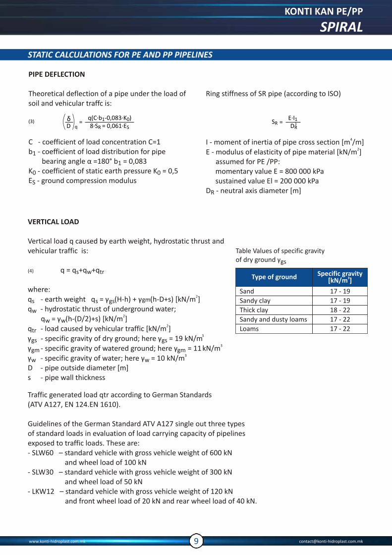
Vertical load q caused by earth weight, hydrostatic thrust and vehicular traffic is:
(4) q = q +q +qs w tr
where:q - earth weight q = γgms
q - hydrostatic thrust of underground water;w2 q = γ (h-(D/2)+s) [kN/m ]w w
2q - load caused by vehicular traffic [kN/m ]tr3γ - specific gravity of dry ground; here γ = 19 kN/mgs gs
3γ - specific gravity of watered ground; here γ = 11 kN/mgm gm3γ - specific gravity of water; here γ = 10 kN/mw w
D - pipe outside diameter [m]s - pipe wall thickness
2γ (H-h) + (h-D+s) [kN/m ]s gs
Traffic generated load qtr according to German Standards (ATV A127, EN 124.EN 1610).
Guidelines of the German Standard ATV A127 single out three typesof standard loads in evaluation of load carrying capacity of pipelinesexposed to traffic loads. These are:- SLW60 – standard vehicle with gross vehicle weight of 600 kN
and wheel load of 100 kN- SLW30 – standard vehicle with gross vehicle weight of 300 kN
and wheel load of 50 kN- LKW12 – standard vehicle with gross vehicle weight of 120 kN
and front wheel load of 20 kN and rear wheel load of 40 kN.
PIPE DEFLECTION
Theoretical deflection of a pipe under the load of soil and vehicular traffc is:
C - coefficient of load concentration C=1b - coefficient of load distribution for pipe 1
bearing angle α =180° b = 0,0831
K - coefficient of static earth pressure K = 0,50 0
E - ground compression modulusS
Ring stiffness of SR pipe (according to ISO)
4I - moment of inertia of pipe cross section [m /m]2E - modulus of elasticity of pipe material [kN/m ]
assumed for PE /PP:momentary value E = 800 000 kPasustained value El = 200 000 kPa
D - neutral axis diameter [m]R
Type of ground Specific gravity3[kN/m ]
Sand
Sandy clay
Thick clay
Sandy and dusty loams
Loams
17 - 19
17 - 19
18 - 22
17 - 22
17 - 22
Table Values of specific gravityof dry ground γgs
KONTI KAN PE/PP
SPIRAL
www.konti-hidroplast.com.mk [email protected]

Type of load Type of loadFA
[kN]?FE
[kN]rA
[m]rE
[m]
SLW60
SLW30
LKW12
SLW60
SLW30
LKW12
100
50
40
1,2
1,4
1,5
500
250
80
0,25
0,18
0,18
1,82
1,82
2,26
Load acting on the top of pipe and caused by particular type of standard vehicle can be calculated using the following formulas:
(5) p = ? . a . pv F F
where: ? – dynamic coefficient
(6)
(7)
STATIC CALCULATIONS FOR PE AND PP PIPELINES
Table Coefficients used in calculations of traffic generated load qtr
Soil compression modulus E’s depends not only on degree of compaction but also on type of soil and thickness of cover Hp. Diagram shows minimum values of ground compression modulus E’s for underground water level below pipe and
3specific gravity of the backfill of 19 kN/m and compaction degree acc. to modified Proctor for such grounds as loam, sand and gravel.For covers Hp exceeding 6 m constant value of E’s, corresponding to Hp=6m were assumed.
Thickness of cover above the pipe top Hp {m}
Diagram Ground compression modulus E’s depending on the modified Proctor density of soil and Hp for underground water level below pipe.
Thickness of cover above the pipe top Hp {m}
Diagram Ground compression modulus E’s dependingon the modified Proctor density of soil and Hp for underground water level above pipe.
Diagram shows minimum values of E’s for underground water level above pipe and compaction degree acc. to modified Proctor forsuch grounds as loam, sand and gravel.For covers Hp exceeding 6 m constant value of E’s, corresponding to Hp=6m were assumed.
0 1 2 3 4 5
4000
3500
3000100%
2500
90%2000
85%1500
80%1000
75%500
E's
[kP
a]
0 1 2 3 4 5 6
4000
3500
3000100%
2500
90%2000
85%1500
80%1000
75%500
E's
[kP
a]
COMPRESSION MODULUS E’S OF THE PIPE SURROUNDING GROUND
www.konti-hidroplast.com.mk [email protected]

STATIC CALCULATIONS FOR PE AND PP PIPELINES
One of parameters defining foundation conditions that may be selected in the program is Modified Proctor Density (MPD). Its value is slightly smaller in comparison with Standard Proctor Density (SPD), however, no direct and clear quantitative relation exists between these two numbers.This relation is closely connected with type of soil. In common practice, for non-cohesive soil used for pipeline foundations, Modified ProctorDensity constitutes reliable parameter to define mechanical properties of soil.
External pressure (generated by soil and underground water) that generates circumferential compressive stress in the pipe wall may lead to buckling damages of pipe. Buckling risk depends on external pressure (Hp and h), possible negative pressure inside the pipe, pipe ring stiffness and type of soil. As regards pipes laid in grounds with relatively high and uniform compaction, risk of buckling is small.Permissible (critical) load can be calculated using the following formula:
(8)
where:F - factor of safety, here F = 2E’ - ground deformation modulus, here E’t = 2E’stδ/D - total relative pipe deflectionmLong-term pipe ring stiffness S = 0,25 S was Rl Rassumed in this formula.For pipes with low ring stiffness, laid down in shallow trenches (Hp < 1.5 m)
and subjected to vehicular traffic loads, the following formula is additionally used:
(9)
Short-term pipe ring stiffness should be used here.
Dimensioning criteria are: short-term relative deflection and critical pressure causing buckling.
In order to obtain proper value of Modified Proctor Density for pipe backfilling, with particular consideration given to the sub-base zone, it is necessary to choose appropriate type of soil, thickness of compacted layers and suitable compacter equipment. Methods for ground compaction are shown in Table
MODIFIED PROCTOR DENSITY VERSUS STANDARD PROCTOR DENSITY
Table Values of Standard Proctor Density and relevant valuesof Modified Proctor Density
Max. layer thickness Number of cyclesWeight
[kg]Type of
equipment Gravel,sand
Loam, clay,silt
85 %of Modified
Proctor Density
90 %of Modified
Proctor Density
Manualtamper
Vibratorycompactor
Dustvibrator
50 - 100
100 - 200
400 - 600
0,15
0,20
0,40
-
-
0,20
1
15 Min.
50 - 100
4
1
1
3
3
0,30
0,15 0,10
0,20 - 0,25
Standard ProctorDensity
Modified ProctorDensity
88
93
85
90
BUCKLING
KONTI KAN PE/PP
SPIRAL
www.konti-hidroplast.com.mk [email protected]

STATIC CALCULATIONS FOR PE AND PP PIPELINES
LAYING GRAVITY PIPELINES IN THE GROUND
MAXIMUM SHORT-TERM DEFECTION
Recommended maximum short-term deflection is 6%. This value includes considerable margin for unpredictable effects resulting from operating conditions rather than from strength of pipe material.Excessive pipe deflection and self-consolidation of the backfill soil may lead to surface damages. When tube jointing sleeves are used, excessive pipe deflection may result in unsealed joints.Verification of permissible load is based on the formulas:
- for Hp ≤1,5m - formula (8) assuming long-term pipe ring stiffnessS = 0,25S and formula (9) when short-term pipe ring stiffness S is assumed. Rl R Rl
Smaller permissible load of the two values calculated according to theabove scheme is considered reliable value.
- for Hp > 1,5 m – formula (8) assuming long-term pipe ring stiffnessS = 0,25SRl R
For thermoplastics pipes laid down in ground, buckling will rarely havedecisive effect on load carrying capacity.
Soil group Type of soils
Single size gravel, highly screenedgravel, mix of gravel and sand, mix ofpoorly-screened gravel and sand.
Crushed rock, river gravel, morainic gravel, volcanic ashes
Single size gravel, mix of sand and gravel, mix of poorly screened graveland sand.
Dune sand and alluvialdeposits, morainic gravel,coast sand
Gravel with silt, gravel with clay, sandwith silt, sand with clay, poorly screenedmix of gravel, silt and sand. Inorganic silt, fine sand with silt andclay, inorganic clay.
Organic silt, clayish organic silt, organic clay, clay with organic mix
Peat, other highly organic soils, sludge Peat, sludge
Gravel with clay, sand with soil, alluvial clay
Soil, alluvial marl, clay
Superficial layer, tufa sand, sea limestone, mud, soil
Name ExampleNo
Granular soil
Granular soil
Cohesive soil
Organic soil
Organic soil
1
2
3
4
5
6
SOIL CLASSIFICATION
Table Classification of soil used for pipe-laying according to Standard ENV 1046:2001
www.konti-hidroplast.com.mk [email protected]

Type of soil Max. slope H:x
Highly cohesive
Rocky
Other cohesive soils
Non-cohesive
2:1
1:1
1:1.25
1:1.5
Permissible slope in open trench without boarding
Type of soil Max. trench depth
Solid rocky ground
without cracks
Cohesive soils
Other soils
4,0m
1,5m
1,0m
Permissible depth of vertical wall trench without boarding
Name ofsoil
Fine gravel
Medium gravel
Coarse gravel
2,0 - 6,0
6,0 - 20,0
20,0 - 60,0Z
Dusty clay
Clay
Sandy clay
0,002 - 0,006
0,006 - 0,02
0,02 - 0,06
Loam
Symbol Sub-type Fraction [mm]
Fine sand
Medium sand
Coarse sand
0,06 - 0,2
0,2 - 0,6
0,5 - 2,0
Clay
Sand
Gravel
I
G
P
<0,002
LAYING GRAVITY PIPELINES IN THE GROUND
Classification of mineral soils
x
H
Sectional view of open trench without boarding
H
Sectional view of vertical wall trench without boarding
Table Slopes in open trench without boarding.
Table Slopes in open trench without boarding.
For other cases sloping should be indicated in the engineering design
TRENCH CONSTRUCTION
Open trench without boarding
a. Open trench, sloping walls without boards In case of trenches up to 4.0 m deep with no underground water and without land slips, with no load on surcharge within reach of soil wedge, the following safe sloping is allowed:
b. Open trench with vertical walls without boardingSuch trench is allowed in a dry soil only provided the ground is not under the load of a bank or construction equipment located near trench edges at a distance less than one trench depth H. Excavated material should be stored at least 0.5 m away from trench edges while the damp must not present any risk to stability of the trench walls.
KONTI KAN PE/PP
SPIRAL
www.konti-hidroplast.com.mk [email protected]

LAYING GRAVITY PIPELINES IN THE GROUND
METHOD FOR INSTALLATION OF PIPELINES IN THE GROUND
Table Required granulation of soil
Preparation of subgrade
1
Main and upper backfills
2
3
NO SOIL COMPACTION
Determination of soil conditions is crucial for engineering design that precedes earth work and laying a pipeline in the ground
(1) Subgrade: soil compacted to approx. 90 – 95% SPD
Layer of approx. 100-150 mm, gravel, sand, well graded aggregate, loam, clay (group 1 – 4 in the table), manual compaction.Pipes should be laid down at the trench bottom so that they evenly rest on subgrade along their entire length.Strength of subgrade may not be less than assumed in the engineering design (static calculations of pipeline). Moreover, hydraulic gradient should be ensured.
Main backfill (2) and upper backfill (3): soil compacted to approx. 90 – 95% SPD
Backfill should be symmetrical at both sides of pipe in layers not exceeding 0.2 m, paying particular attention to careful compactionof soil in pipe support zone. It is necessary to ensure that pipe would not go up during compacting operation. Use of light vibratory equipment(weight up to 100kg) is recommended. Use of the compactor directly above pipeline is not allowed. This may be used only when the cover is at least 0.3 m thick.For the first layer - up to 0.3 m thick - material belonging to group 1-4 with granularity specifi ed in Table should be used.
Virgin soil may be used for backfilling in the pipe foundation zone provided it satisfies all the criteria given below:
a) does not contain particles larger than allowed for given pipe diameter as per table;
b) does not contain lumps larger than double size of particles for specific application as shown in table;
c) if the material is not frozen;d) does not contain foreign matter (such as asphalt,
bottles, cans, pieces of wood)e) if compaction using flexible material is required.
If no detailed information about original material is available, density factor of 91 to 97% acc. to Standard Proctor Density (SPD) is assumed.
SystemNominal
diameter of pipeMaximum
particle size
KK SPIRAL(manholes,
tanks, fittings)1300 < DN ≤ 2000 50
www.konti-hidroplast.com.mk [email protected]

LAYING GRAVITY PIPELINES IN THE GROUND
Sectional view of a trench made in the green belt area
4
Sectional view of a trench made under street
4
BACKFILL
The green belt: If a pipeline is laid down in the green belt area, virgin soil (from excavation) It may be used since it belongs to group 1-4. In this case it should be compacted to approx. 88% SPD.
EXCAVATION WATER DRAINAGE
Lowering of the water table in trench should be done if excavation work or laying the pipelines is hindered by underground water. Lowering of the water table should be done without disturbing subgrade soil structure or subgrade soil of neighbouring buildings. Underground water tableshould be lowered by minimum 0.5 m below the trench bottom. Due to harmful effect of water table variations on the trench bottom soil structure, lowering of the underground water table should include 24-hour periods. Moreover, excavated trench should be protected against inflow of rain water. Structures protecting trench walls should stand out at least 0.15 m above the adjacent ground, while ground surface should be suitably sloped for easier water removal.
Any loose ground (dewatered for the time of construction) without grains exceeding 20 mm(not more than 16 mm in case of crushed stone) or cohesive soil satisfying the requirements for grounds with symbols ms, ss, be used as subgrade for the pipeline. Strength parameters of subgrade may not be worse than assumed in the design documentation (static calculations for the pipeline). If cohesive soil occurs at the trench bottom, a layer of loose ground backfi ll not less than 0.15 m thick and not less than 0.25 pipe diameter should be made before the pipeline is laid down. This backfill should be compacted up to 95% SPD. Pumping of underground water may be stopped only when the pipeline is completely backfilled. Civil engineering design must describe detailed method for trench dewatering.
Excavations under the streets: Virgin soil may be used for backfilling. Vibratory equipment with weight of up to 200 kg may be used also. Density according to SPD should satisfy the requirements for road construction.For pipelines laid under streets frost heave soils may not be used as upper layer of backfill (thickness depending on frost penetration conditions).
KONTI KAN PE/PP
SPIRAL
www.konti-hidroplast.com.mk [email protected]

RECOMMENDED METHODS FOR SOIL COMPACTION
The structural properties of the pipe zone backfill material are primarily dependent upon the type of material and the degree of compaction achieved. The degree of compaction can be varied by using different types of equipment and by varying the numbers of layers. Table represents groups of material classified in conformance with Annex A the degree of compaction expressed in Standard Proctor Density (SPD) for the three classes of compaction used in this prestandard, i.e “W”, “M” or “N”.
NOTE Proctor Density determined in accordance with DIN 18127
Class of compaction 4 3 2 1
N (not)
M (moderate)
W (well)
75-80 %
81-89 %
90-95 %
79-85 %
86-92 %
93-96 %
84-89 %
90-95 %
96-100 %
90-94 %
95-97 %
98-100 %
Embankment group
back?ll
upper back?ll
top charge
b
subgrade (bottom back?ll)
Division of trench into zones of virgin soil (2) and
the ground around pipeline (1)
Layers of soil with different density
12
SELECTION OF PIPE STIFFNESS FOR THE TYPE OF GROUND
Type of ground and degree of its compaction are crucial factors in construction of gravity pipelines.
LAYING GRAVITY PIPELINES IN THE GROUND
www.konti-hidroplast.com.mk [email protected]

Selected pipe stiffness should be verified by static calculations (e.g. according to Scandinavian Method). In general, it is assumed that the trench is dewatered prior to installation. If underground wateris present, allowance for additional pipe load should be made in pipeline calculations.In general, selection of pipe stiffness depends on the type of virgin soil, top charge material and its density, thickness of cover above pipe, water table, size and geometry of load as well as the boundary values for given pipe.Matching pipeline stiffness with installation conditions should be agreed with the designer. Tables below show general values of ring stiffness relative to given ground properties
LAYING GRAVITY PIPELINES IN THE GROUND
KONTI KAN PE/PP
SPIRAL
www.konti-hidroplast.com.mk [email protected]
Recommended minimum stiffness for pipes laid in ground not exposed to traffic generated loads
Recommended minimum stiffness for pipes laid in ground not exposed to traffic generated loads
1
1 W
W
W
W
W
W
W
W
2
2
3
3
4
4
1
1
2
2
3
3
4
4
Backfill material[Group]
Backfill material[Group]
Class of density
Class of density
2Pipe stiffness [kN/m ]
2Pipe stiffness [kN/m ]
1 m < Thickness of cover < 3 m
1 m < Thickness of cover < 3 m
Virgin soil group
Virgin soil group
WM
44
44
44
44
48
8888
88
48
44
44
8**
88
88
48
8**
8**
8**
WMWMWM
WMWMWMWM
1
1
2
2
3
3
4
4
5
5*
6
6*
44
44
44
48
88
888**
88
88
48
48
****
8**
8**
8**
****
****
****
3 m < Thickness of cover < 6 m
3 m < Thickness of cover < 6 m
*) In grounds with low carrying capacity, pipe foundation should be reinforced e.g. with geotextiles **) Static calculations are necessary for determination of geometry of trench and pipe stiffness.
*) In grounds with low carrying capacity pipe foundation should be reinforced e.g. with geotextiles**) Static calculations are necessary for determination of geometry of trench and pipe stiffness.In addition, when pipeline is laid under unsurfaced road (particularly if depth is small) pipeline may be covered with reinforced slabs for greater safety.
4
4
4
8
4
4
8
8
8
4
4
8
8
8
**
**
8
8
8
**
8
**
**
**
8
8
8
**
**
**
**
**
8
8
**
**
Equipment
Number of presses for compaction class
Maximum layer thickness, in metres, after compaction
for soil group
Minimum thicknessover pipe crown
before compaction
Well Moderate 1 2 3 4 m
see soil group table
Foot or hand tempermin. 15kg
3
3
4
4
4
4
4
6
6
6
6
6
6
6
6
6
1
1
1
1
1
1
1
2
2
2
2
2
2
2
2
2
0,15
0,30
0,10
0,15
0,20
0,30
0,40
0,35
0,60
1,00
1,50
0,15
0,25
0,35
0,50
0,25
0,10
0,25
-
0,10
0,15
0,25
0,30
0,25
0,50
0,75
1,10
0,10
0,20
0,30
0,40
0,20
0,10
0,20
-
-
0,10
0,15
0,20
0,20
0,30
0,40
0,60
-
0,15
0,20
0,30
0,20
0,10
0,15
-
-
-
0,10
0,15
-
-
-
-
-
-
-
-
-
0,20
0,30
0,15
0,15
0,20
0,30
0,50
0,60
1,20
1,80
2,40
0,20
0,45
0,60
0,85
1,00
Plate vibrator
min. 50kg
min. 100kg
min. 200kg
min. 400kg
min. 600kg
Vibrating roller
min. 15kN/m
min. 30kN/m
min. 45kN/m
min. 65kN/m
Twin vibrating
min. 5kN/m
min. 10kN/m
min. 20kN/m
min. 30kN/m
Vibrating tampermin. 70kg
Triple heavy roller(no vibration)min. 50kN/m
LAYING GRAVITY PIPELINES IN THE GROUND
RECOMMENDED COMPACTION METHODS
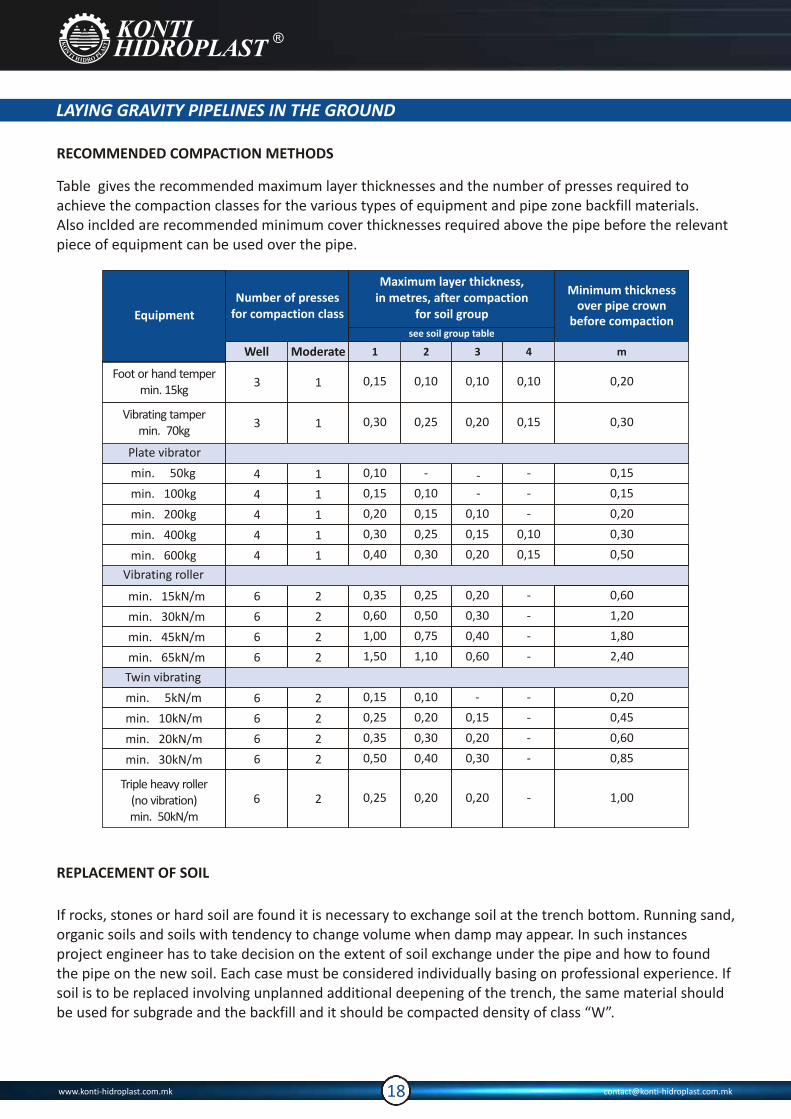
Table gives the recommended maximum layer thicknesses and the number of presses required to achieve the compaction classes for the various types of equipment and pipe zone backfill materials. Also inclded are recommended minimum cover thicknesses required above the pipe before the relevant piece of equipment can be used over the pipe.
REPLACEMENT OF SOIL
If rocks, stones or hard soil are found it is necessary to exchange soil at the trench bottom. Running sand, organic soils and soils with tendency to change volume when damp may appear. In such instances project engineer has to take decision on the extent of soil exchange under the pipe and how to found the pipe on the new soil. Each case must be considered individually basing on professional experience. If soil is to be replaced involving unplanned additional deepening of the trench, the same material should be used for subgrade and the backfill and it should be compacted density of class “W”.
www.konti-hidroplast.com.mk [email protected]
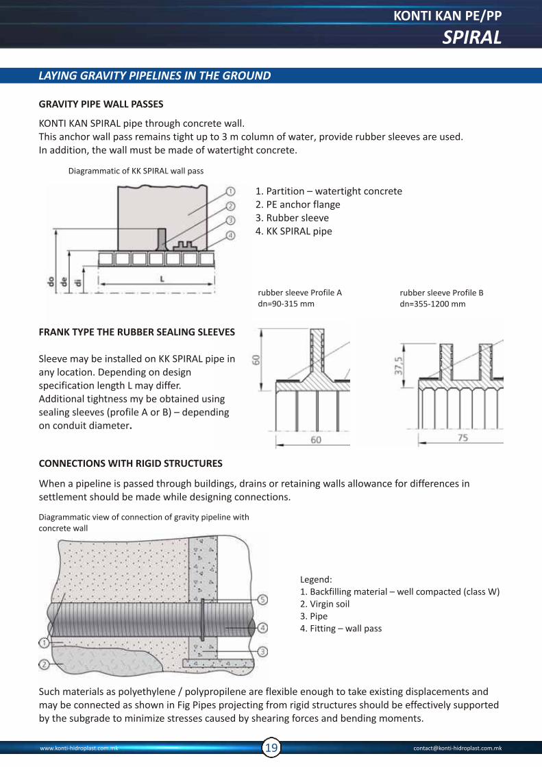
rubber sleeve Profile Bdn=355-1200 mm
rubber sleeve Profile Adn=90-315 mm
LAYING GRAVITY PIPELINES IN THE GROUND
GRAVITY PIPE WALL PASSES
KONTI KAN SPIRAL pipe through concrete wall.This anchor wall pass remains tight up to 3 m column of water, provide rubber sleeves are used. In addition, the wall must be made of watertight concrete.
Diagrammatic of KK SPIRAL wall pass
1. Partition – watertight concrete2. PE anchor flange3. Rubber sleeve4. KK SPIRAL pipe
FRANK TYPE THE RUBBER SEALING SLEEVES
Sleeve may be installed on KK SPIRAL pipe in any location. Depending on design specification length L may differ.Additional tightness my be obtained using sealing sleeves (profile A or B) – depending on conduit diameter.
CONNECTIONS WITH RIGID STRUCTURES
When a pipeline is passed through buildings, drains or retaining walls allowance for differences in settlement should be made while designing connections.
Diagrammatic view of connection of gravity pipeline withconcrete wall
Legend:1. Backfilling material – well compacted (class W)2. Virgin soil3. Pipe4. Fitting – wall pass
Such materials as polyethylene / polypropilene are flexible enough to take existing displacements and may be connected as shown in Fig Pipes projecting from rigid structures should be effectively supported by the subgrade to minimize stresses caused by shearing forces and bending moments.
KONTI KAN PE/PP
SPIRAL
www.konti-hidroplast.com.mk [email protected]

DIMENSIONS
GRAVITY PIPE CONNECTIONS
IN-SITU CONNECTIONS WITH EXISTING COLLECTOR / MANHOLE
Dimensions of In-Situ connections
OD 110
ID 110
OD 160
ID 160
OD 200
ID 200
OD 250
ID 250
OD 315
ID 300
114
125
166
193
208
240
262
295
337
355
Diametar of knife (mm)
OD / ID
www.konti-hidroplast.com.mk [email protected]
DN OD ID Thickness of profile (e)Heigh of
profile (H)
mm
1300
1400
1500
1600
1800
2000
mm
1422
1534
1655
1765
1975
2205
mm
1302
1404
1505
1605
1805
2005
mm
5
5,2
5,9
6,3
7
8,2
mm
5,5
5,7
6,5
6,93
7,7
9
mm
6,05
6,3
7,15
7,16
8,5
10
mm
60
65
75
80
85
100
SN 4 SN 8 SN 10
Signify dimensions and weights in the table are indicative and they are applying on class wich is responding on the require product. The signify values are medial values for manufacture. Table shows the guaranteed manufacturing values provided for by EN 13476 and SFS 5906:2004 standards.

GRAVITY PIPE CONNECTIONS
SNAP-JOINT CONNECTION
Before connection, pipes should be aligned coaxially and then one pipe end should be pushed into another with the use of excavator. Force F required to make this connection varies depending on pipe diameter. Snap on terminal is factory fitted on the pipe end.
SNAP-JOINT
Connection is a permanent joint.
di
[mm] [mm]
1300
1400
1500
1600
1800
2000
L
219
219
267
267
314
314
EXTRUSION WELDING CONNECTION
Extrusion welding is connection of KK SPIRAL pipe with use of hand extruder using same material made PE/PP rod.
KONTI KAN PE/PP
SPIRAL
www.konti-hidroplast.com.mk [email protected]
3. Place In-Situ connector in the hole 4. Insert connection pipe in the rubber In-Situ connector
1. Define connection diameter 2. Cut suitable hole in the manhole wall
IN-SITU CONNECTOR SHOULD BE USED FOR MAKING CONNECTION WITH COLLECTOR OR MANHOLE.
Proceed as follows:
GRAVITY PIPE CONNECTIONS
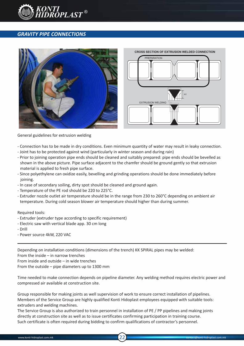
General guidelines for extrusion welding
- Connection has to be made in dry conditions. Even minimum quantity of water may result in leaky connection.- Joint has to be protected against wind (particularly in winter season and during rain)- Prior to joining operation pipe ends should be cleaned and suitably prepared: pipe ends should be bevelled as
shown in the above picture. Pipe surface adjacent to the chamfer should be ground gently so that extrusion material is applied to fresh pipe surface.
- Since polyethylene can oxidize easily, bevelling and grinding operations should be done immediately before joining.
- In case of secondary soiling, dirty spot should be cleaned and ground again.- Temperature of the PE rod should be 220 to 225°C.- Extruder nozzle outlet air temperature should be in the range from 230 to 260°C depending on ambient air
temperature. During cold season blower air temperature should higher than during summer.
Required tools:- Extruder (extruder type according to specific requirement)- Electric saw with vertical blade app. 30 cm long- Drill- Power source 4kW, 220 VAC
H1
EXTRUSION WELDING
CROSS SECTION OF EXTRUSION WELDED CONNECTION
PREPARATION
Depending on installation conditions (dimensions of the trench) KK SPIRAL pipes may be welded:From the inside – in narrow trenchesFrom inside and outside – in wide trenchesFrom the outside – pipe diameters up to 1300 mm
Time needed to make connection depends on pipeline diameter. Any welding method requires electric power and compressed air available at construction site.
Group responsible for making joints as well supervision of work to ensure correct installation of pipelines. Members of the Service Group are highly qualified Konti Hidoplast employees equipped with suitable tools: extruders and welding machines.The Service Group is also authorized to train personnel in installation of PE / PP pipelines and making joints directly at construction site as well as to issue certificates confirming participation in training course. Such certificate is often required during bidding to confirm qualifications of contractor’s personnel.
www.konti-hidroplast.com.mk [email protected]

LEAK PROOF TESTS FOR GRAVITY PIPELINES
LEAK PROOF TEST OF GRAVITY PIPELINES (WITH FLOW CAUSED BY GRAVITY)
General
The following components are subjected to water-pressure test at the construction site:
• Gravity thermoplastics pipelines, in sections of limited length (e.g. between manholes);
• Pipelines composed of KK SPIRAL pipes 1000 m long Maximum;
• Manholes.
Tested pipeline is filled with clean water and pressurized with definite hydrostatic pressure. Leaktightness is assessed by measuring amount of water necessary to fill in for retaining required pressure or water level in the pipeline.
Required minimum test pressure:
P01 = 10 kPa = 0,1 bar = 1,0 m column of water, and maximum 50kPa, on top of the pipeIf underground water is present, test pressure depends on the difference of levels between pipeline axis and underwater water tableP02 = P01 + 1,1 x a (m column of water]) (2)
where:
min or 5.0 m maxP01 = 1,0 m column of water, a = pressure exerted by underground water(m column of water)
Test pressure values relative to pipeline level and underground water table
Hydraulic test procedure acc. to EN 1610
Difference in height between
pipeline axis and underground
water table
Test pressure P01
a (m)
a<0
0<a<0.5
0.5<a<1.0
1.0<a<1.5
1.5<a<2.0
2.0<a<2.5
2.5<a<3.0
3.0<a<3.5
3.5<a<4.0
4.0<a<4.5
4.5<a<5.0
kPa
10.0
15.5
21.0
26.5
32.0
37.5
43.0
48.5
54.0
59.5
65.0
mm H O2
1000
1550
2100
2650
3200
3750
4300
4850
5400
5950
6500
Phase I:Test pressure or water level increased to:
P = 1,0 + 1,1 a (column of water)e1Prior to starting Phase II maintain pressure Pe1 for at least 10 minutes
Phase II:
Phase III:
Test pressure P = 1,0 + 1,1 a (m column of water) is maintained for half an hour by adding water to the pipelinee1 (if necessary).Amount of makeup water is measured 3 times, always for 6 minutes, in litres (Q ,Q ,Q ). 1 2 3
Conclusion of the test.
Average value of Q , Q , Q is calculated: Q = 1/3 x (Q + Q + Q ) (3)1 2 3 a 1 2 3Next, Q is transformed into Q , expressed in litres/m x hour:a ap k1 = 60 / 6 = 10 (1/hour) k2 = 1/L (L = lenght of section under test)
Q = Q x k1 x k2 (4)ap a
Test result is satisfactory if Qap value remains in the shaded area - see Diagram 10.1.a
NOTE: 100 kPa = 1 bar = 1 atm = 10 m column of water.
Temperature of water inside pipeline during test:
T = 20°C +∆T; ∆T<10°Cmean
(for gravity fl ow pipes)
Temperature of leakage makeup water:
T = T ± 3°Ca mean
Explanation of symbols are used:L = ength of pipeline section under test;a = underground water table measured from pipe axis in the middleof tested section (1/2 L)Di = Pipeline inside diameterPe1 = test pressure
Test pressure may be calculated using the formula:Pe1 = P10 + 1,1 a (m column of water) (2)where: P10 = 1,0 m column of water (= 1,0 x 10⁻² kPa)
KONTI KAN PE/PP
SPIRAL
www.konti-hidroplast.com.mk [email protected]
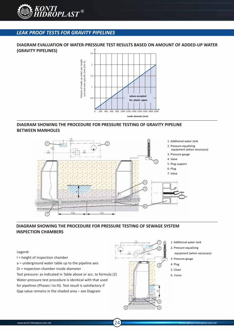
1. Additional water tank
2. Pressure equalizing equipment (when necessary)
3. Pressure gauge
4. Valve
5. Plug support
6. Plug
7. Valve
LEAK PROOF TESTS FOR GRAVITY PIPELINES
DIAGRAM EVALUATION OF WATER-PRESSURE TEST RESULTS BASED ON AMOUNT OF ADDED-UP WATER (GRAVITY PIPELINES)
1. Additional water tank
2. Pressure equalizing
equipment (when necessary)
3. Pressure gauge
4. Plug
5. Chain
6. Valve
Inside diameter [mm]
Vo
lum
e o
f m
ake-
up
wat
er p
er le
ngt
hu
nit
an
d o
ver
spec
ific
tim
e [l
/m h
]
DIAGRAM SHOWING THE PROCEDURE FOR PRESSURE TESTING OF GRAVITY PIPELINE BETWEEN MANHOLES
DIAGRAM SHOWING THE PROCEDURE FOR PRESSURE TESTING OF SEWAGE SYSTEMINSPECTION CHAMBERS
Legend:
l = height of inspection chamber
a = underground water table up to the pipeline axis
Di = inspection chamber inside diameter
Test pressure: as indicated in Table above or acc. to formula (2)
Water-pressure test procedure is identical with that used
for pipelines (Phases I to III). Test result is satisfactory if
Qap value remains in the shaded area – see Diagram
www.konti-hidroplast.com.mk [email protected]
0 200 400 600 800 1000 1200 1400 1500 1600 1800 2000
0,5
1
1,5
2
2,5
values accepted
for plastic pipes
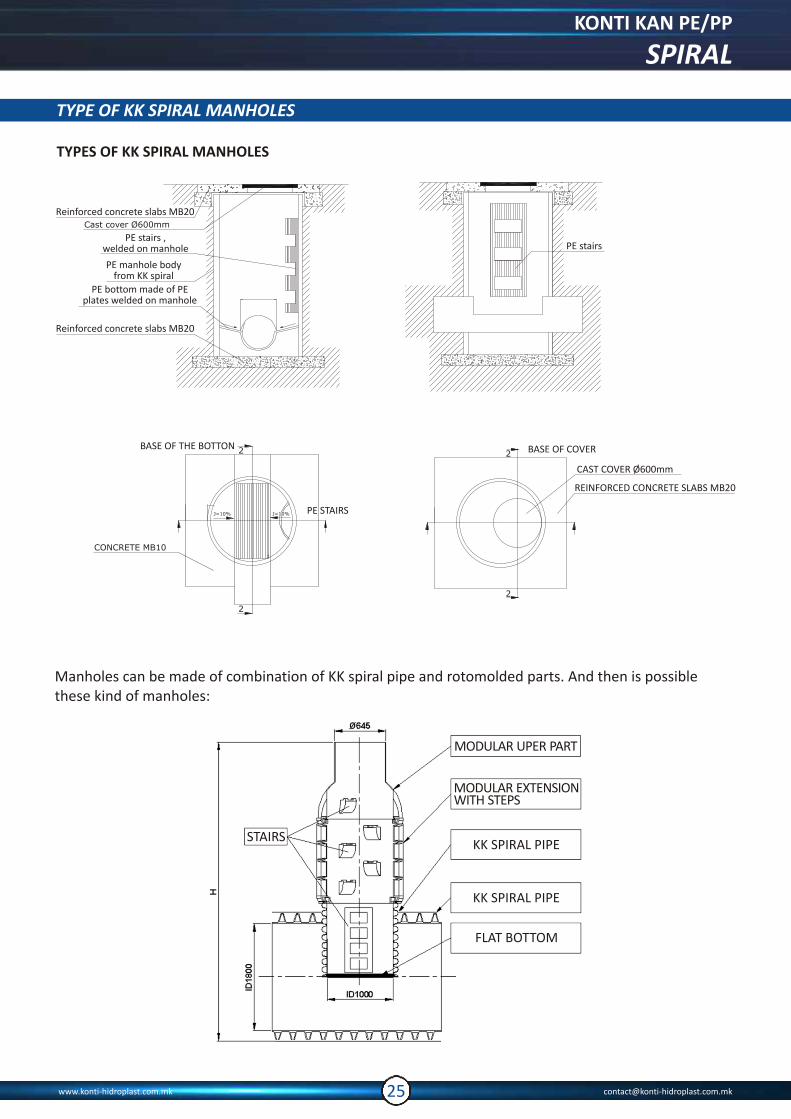
TYPES OF KK SPIRAL MANHOLES
2
BASE OF THE BOTTON
CONCRETE MB10
PE STAIRS
2
2
Ј=10% Ј=10%Ј=10%Ј=10%
BASE OF COVER
CAST COVER Ø600mm
REINFORCED CONCRETE SLABS MB20
PE stairs
2
2
TYPE OF KK SPIRAL MANHOLES
Reinforced concrete slabs MB20Cast cover Ø600mm
PE stairs , welded on manhole
Reinforced concrete slabs MB20
PE manhole body from KK spiral
PE bottom made of PEplates welded on manhole
Manholes can be made of combination of KK spiral pipe and rotomolded parts. And then is possible these kind of manholes:
STAIRSKK SPIRAL PIPE
KK SPIRAL PIPE
FLAT BOTTOM
MODULAR UPER PART
MODULAR EXTENSIONWITH STEPS
KONTI KAN PE/PP
SPIRAL
www.konti-hidroplast.com.mk [email protected]
TYPE OF KK SPIRAL MANHOLES
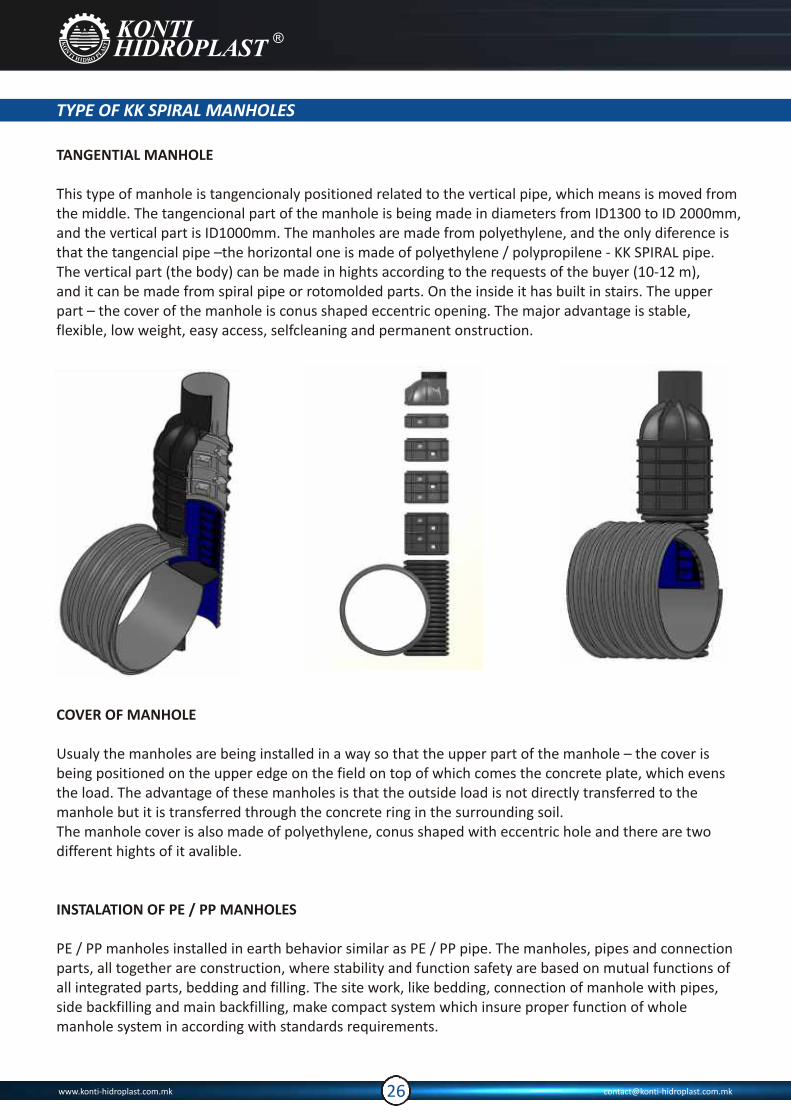
TANGENTIAL MANHOLE
This type of manhole is tangencionaly positioned related to the vertical pipe, which means is moved from the middle. The tangencional part of the manhole is being made in diameters from ID1300 to ID 2000mm, and the vertical part is ID1000mm. The manholes are made from polyethylene, and the only diference is that the tangencial pipe –the horizontal one is made of polyethylene / polypropilene - KK SPIRAL pipe.The vertical part (the body) can be made in hights according to the requests of the buyer (10-12 m), and it can be made from spiral pipe or rotomolded parts. On the inside it has built in stairs. The upper part – the cover of the manhole is conus shaped eccentric opening. The major advantage is stable, flexible, low weight, easy access, selfcleaning and permanent onstruction.
COVER OF MANHOLE
Usualy the manholes are being installed in a way so that the upper part of the manhole – the cover is being positioned on the upper edge on the field on top of which comes the concrete plate, which evens the load. The advantage of these manholes is that the outside load is not directly transferred to themanhole but it is transferred through the concrete ring in the surrounding soil.The manhole cover is also made of polyethylene, conus shaped with eccentric hole and there are two different hights of it avalible.
INSTALATION OF PE / PP MANHOLES
PE / PP manholes installed in earth behavior similar as PE / PP pipe. The manholes, pipes and connection parts, all together are construction, where stability and function safety are based on mutual functions of all integrated parts, bedding and filling. The site work, like bedding, connection of manhole with pipes, side backfilling and main backfilling, make compact system which insure proper function of whole manhole system in according with standards requirements.
www.konti-hidroplast.com.mk [email protected]
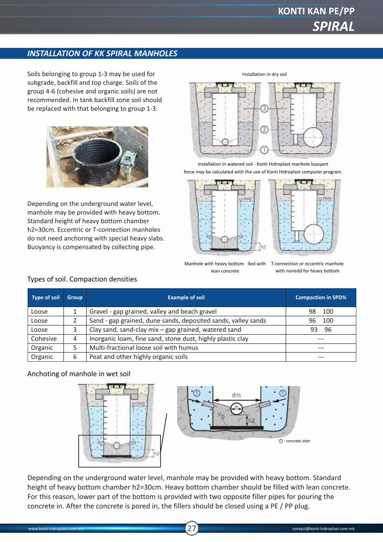
Installation in dry soil
Installation in watered soil - Konti Hidroplast manhole buoyant
force may be calculated with the use of computer program.Konti Hidroplast
Manhole with heavy bottom ?lled with
lean concrete
T-connection or eccentric manhole
Soils belonging to group 1-3 may be used for subgrade, backfill and top charge. Soils of the group 4-6 (cohesive and organic soils) are not recommended. In tank backfill zone soil should be replaced with that belonging to group 1-3.
Depending on the underground water level, manhole may be provided with heavy bottom. Standard height of heavy bottom chamber h2=30cm. Eccentric or T-connection manholes do not need anchoring with special heavy slabs. Buoyancy is compensated by collecting pipe.
- concrete inlet
INSTALLATION OF KK SPIRAL MANHOLES
Anchoting of manhole in wet soil
Type of soil
Loose
Loose
Loose
Cohesive
Organic
Organic
Gravel - gap grained, valley and beach gravel
Sand - gap grained, dune sands, deposited sands, valley sands
Clay sand, sand-clay mix – gap grained, watered sand
Inorganic loam, fine sand, stone dust, highly plastic clay
Multi-fractional loose soil with humus
Peat and other highly organic soils
1
2
3
4
5
6
98 ? 100
96 ? 100
93 ? 96
---
---
---
Group Example of soil Compaction in SPD%
Types of soil. Compaction densities
Depending on the underground water level, manhole may be provided with heavy bottom. Standard height of heavy bottom chamber h2=30cm. Heavy bottom chamber should be filled with lean concrete. For this reason, lower part of the bottom is provided with two opposite filler pipes for pouring the concrete in. After the concrete is pored in, the fillers should be closed using a PE / PP plug.
with nonedd for heavy bottom
KONTI KAN PE/PP
SPIRAL
www.konti-hidroplast.com.mk [email protected]
INSTALLATION OF KK SPIRAL MANHOLES
CHECKING HYDROSTATIC STABILITY OF SEWAGE MANHOLES
In order to check hydrostatic stability of a sewage manhole we should compare the design value of hydrostatic lift exerted on the manhole with the sum of values of the bearing forces (tare weight and friction of the soil against the external lateral surface of the manhole).The calculation diagram is shown in fig Checking of hydrostatic stability refers to such design cases, where the ratio between the nominal diameter of the collector and diameter of manhole chamber does not exceed 0.7 and the nominal diameter of manhole is at least 800 mm. In other cases, especially when the collector diameter is larger than diameter of manhole chamber, the calculation of additional load can be neglected. If the condition for manhole hydrostatic stability is not met, the manhole must be equipped with a loading chamber filled with concrete, placed in the bottom part of the manhole.
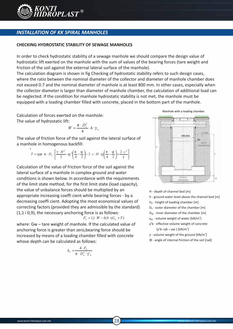
Calculation of forces exerted on the manhole:The value of hydrostatic lift:
The value of friction force of the soil against the lateral surface of a manhole in homogenous backfill:
Calculation of the value of friction force of the soil against the lateral surface of a manhole in complex ground and water conditions is shown below. In accordance with the requirements of the limit state method, for the first limit state (load capacity), the value of unbalance forces should be multiplied by an appropriate increasing coeffi cient while bearing forces - by a decreasing coeffi cient. Adopting the most economical values of correcting factors (provided they are admissible by the standard) (1,1 i 0,9), the necessary anchoring force is as follows:
where: Gw – tare weight of manhole. If the calculated value of anchoring force is greater than zero,bearing force should be increased by means of a loading chamber filled with concrete whose depth can be calculated as follows:
Manhole with a loading chamber.
H - depth of channel bed [m]
h - ground water level above the channel bed [m]
h - height of loading chamber [m]2
D - outer diameter of the chamber [m]z
D - inner diameter of the chamber [m]w3γ - volume weight of water [kN/m ]w
γ'b - effective volume weight of concrete3 (γ'b =γb – γw ) [kN/m ]
3γ - volume weight of the ground [kN/m ]
Φ - angle of internal friction of the soil [rad]
www.konti-hidroplast.com.mk [email protected]
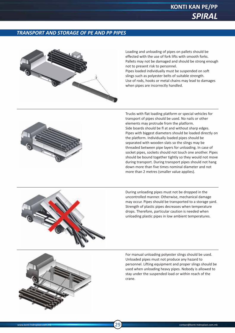
Trucks with flat loading platform or special vehicles for transport of pipes should be used. No nails or other elements may protrude from the platform.Side boards should be fl at and without sharp edges. Pipes with biggest diameters should be loaded directly on the platform. Individually loaded pipes should be separated with wooden slats so the slings may be threaded between pipe layers for unloading. In case of socket pipes, sockets should not touch one another. Pipes should be bound together tightly so they would not move during transport. During transport pipes should not hang down more than five times nominal diameter and not more than 2 metres (smaller value applies).
During unloading pipes must not be dropped in the uncontrolled manner. Otherwise, mechanical damage may occur. Pipes should be transported to a storage yard. Strength of plastic pipes decreases when temperature drops. Therefore, particular caution is needed when unloading plastic pipes in low ambient temperatures.
For manual unloading polyester slings should be used. Unloaded pipes must not produce any hazard to personnel. Lifting equipment and proper slings should be used when unloading heavy pipes. Nobody is allowed to stay under the suspended load or within reach of the crane.
Loading and unloading of pipes on pallets should be effected with the use of fork lifts with smooth forks. Pallets may not be damaged and should be strong enough not to present risk to personnel.Pipes loaded individually must be suspended on soft slings such as polyester belts of suitable strength. Use of rods, hooks or metal chains may lead to damages when pipes are incorrectly handled.
TRANSPORT AND STORAGE OF PE AND PP PIPES
KONTI KAN PE/PP
SPIRAL
www.konti-hidroplast.com.mk [email protected]

KK SPIRAL 3,0 - 4,0 m
System Maximum approximate stacking height h [m]
TRANSPORT AND STORAGE OF PE AND PP PIPES
Pipe storage yard should be accessible to personnel, e.g. quality control staff. Easy access should be also provided for further transport. Pipes must not be stored near open fire, sources of heat or dangerous substances: fuel, solvents, oils, paints, etc.
Wooden separators should be used during storage of pipes- in the same way as in transport. Wooden slats should be flat and wide to avoid deformation of pipes. Biggest diameter pipes should be placed at the bottom. In case of socket pipes deformation of sockets should be avoided (alternating arrangement).
Pipes should not rest directly on the floor. It is necessary to use supports- similar to wooden slats placed between pipes.Distance between supports should not exceed 2.5 m.The floor should be flat and without sharp elements. Stacking height should not exceed 3-4 m.
Pipe stacking height
www.konti-hidroplast.com.mk [email protected]
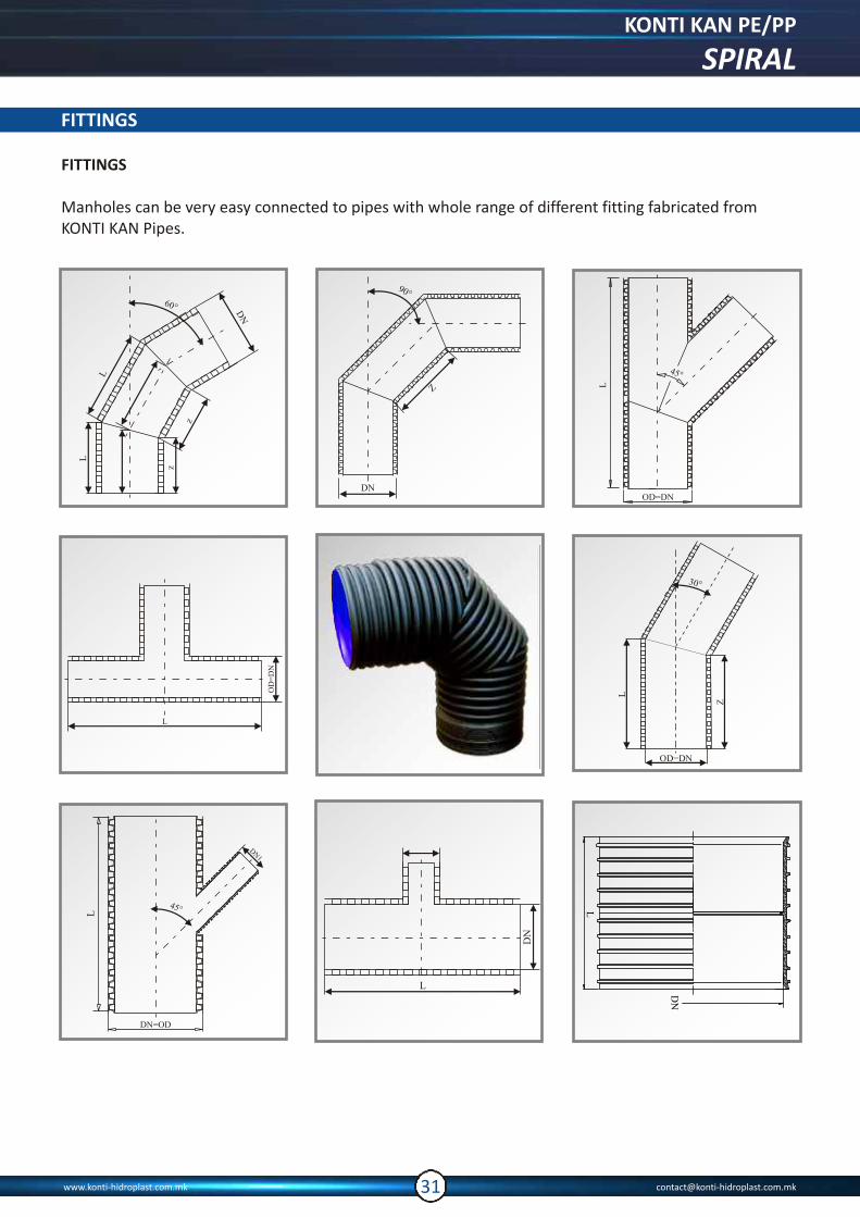
FITTINGS
FITTINGS
Manholes can be very easy connected to pipes with whole range of different fitting fabricated from KONTI KAN Pipes.
KONTI KAN PE/PP
SPIRAL
www.konti-hidroplast.com.mk [email protected]
DN
Z
90°
45°
DN
1
L

Tel:00 389 034 212 06400 389 034 211 75700 389 034 215 22500 389 034 215 226
Fax:00 389 034 211 964
e-mail: [email protected]: [email protected] bb 1480 GevgelijaMACEDONIA
Representatives
Greece
Themis Panayiotidis00 30 210 609 62 43 Croatia Hidrokom00 385 33 620 095 Reus00 385 1 6060 090 Serbia Konti Hidroplast Beograd00 381 21 444 66200 389 71 315 210
Albania Konti Hidroplast Albania 00 389 75 221 043 00 355 67 2022 04300 355 4 2419 304e-mail:[email protected] Bulgaria Eurocom2000 OOD00 359 29 659 095 Mariva SY00 359 28 708 148 BiH and Montenegro 00 389 71 315 210