Embed Size (px)
Citation preview

KKu
J F N4 P r%$.1 S-1 ~ R - 0 -A<
B A.C
Best Available Cop,"
!ICCUlITY CLASSIFICATION OF THIS PAGE (WNien Data Entered)READ INSTRUCTIONS
REPORT DOCUMENTATION PAGE BEFORE COMPLETING FORM
1. REPORT NUMBER 12. GOVT ACCESSION NO. 3. RECIPIENT'S CATALOG NUMBER
_UiSWC TR 82-57 )-IZ4e4. TITLE (and Subtitle) $- TYPE OP "EPORT 6 PERIOD COVEMEb
FinalANALYSIS TECHNIQUES FOR AIRBORNE LASER RANGESAFETY EVALUATIONS 6, PERFORMING ORO. REPORT NUMBER
7. AUTHOR() I. CONTRACT ORRANT NUMIMUR )
M. S. RamsburgD. L. JenkinsR. D. Doerflein
11 PERFORMING ORGANIZATION NAME AND ADDRESS 10, PRQGRAM I0, 1MINTP ROJECT,"tASKAREAl WOPk UNIT NMlMEl
Naval Surface Weapons Center (N41)Dahlgren, VA 22448
1,1 CONTROLLINU OFFICE NAME AND ADDRESS It. REPORT DATE
Naval Electronic Systems Command Au ust 1982Washington, DC 20360 13. NUMBER OF PAGES
__5614, MONITORINO AGENCY NAME i ADDRESS(It diffeent tram Contiollinl Office) I1, SECURITY CLASS, (of this report,)
UNCLASSIFIEDIlla, DECM AUSIIICATION/DOWNGRADiNG
S. DISTRIBUTION STATEMENT (of thli Report)
Approved for public release; distribution unlimited.
17. DISTRIBUTION STATEMENT (of the abstract entered In Block 20, it differemt leam Report)
III SUPPLEMENTARY NOTES
''I
It. KEY WORDS (Continue on reverse side if noceasory and identify by block number)
Airborne lasersLaser hazardsSafety, laserRange
20- ABSTRACT (Continue an reverse olde it necessary end identify by block number)
Techniques to evaluate safety of airborne laser operations on the rangeare reported. The objectives of the safety evaluations were to (a) protectcivilian and military personnel from the hazards associated with lasers,(b) provide users with the least restrictive constraints in which to performtheir mission and still maintain an adequate degree of safety, and (c)develop a data base for the Navy in the event of suspected laser exposure orother related incidents involving military or civilian personnel.
(Continued on back)
DD F .ON.Ns 1473 EDITION OF I NOV 45 IS OBSOLETES/N 0102.LF-014-6601 UNCLASSIFIED
SECURITY CLASSIPICATION OF THIS PAGE (lten Data Entered)
"* ...... ,.. ...," ... .. . . . . . . . . . . . . . . . . . . . . ',

U7N(MAS S ITEDSECURITY CLASSIFICATION Off THIS PAGE (I$7,.n Dsta Entered)
(Block 20 continued)
A microcomputer code, written in ANSIi 77 FORTRAN, has been developed,which will provide safe flight profiles for airborne laser systems. Theoutput of this code can also be used in establishing operating areas forground-based lasers. input to the code includes output parameters, NOHDand assigned buffer zone for the laser system, as well as parameters describ-ing the geometry of the range.
M`1
.4M~q~r~
SE U IYC ASIIAINO HI 4'Wo Dt rtrd

FOREWORD
The Naval Surface Weapons Center was tasked as the Navy's TechnicalDirection Agent for laser safety in 1979 and has been providing technicalassistance to Navy and Marine Corps range personnel and system users in thearea of laser safety, In order to properly assist these personnel, techniques
have been developed to perform safety evaluations of laser operations on theranges. This report discusses the techniques used to perform these evalu-ations.
The assistance provided by H. L. Simpson of the Electro-Optics Branch(Code N54) in the development of these techniques is gratefully acknowleged.
This report hae been reviewed and approved by J. P. Horton, Head, SystemsSafety Division.
Released byt
T. A. CLARE, HeadCombat Systems Department
Aacession ForDTIC NTIS GRA&IS ELECTE DTIC TAB
Unannounced
FEB 1 1983 just•'ioation.Hy---
....Distribution/
Availability CodesAva il arnd/or
Dist Special
Laxis,~ ~~~ ....
O..PY.. .
•.,, ,•: .,.. . •, ?",..•..,'. . .,? , ' . ". , ...,. . . .• •" . ". . .. .' • ,. , . , . . . . . .

CONTENTS
ePage
EXECUTIVE SUMMARY . o • .... • ... .. • .e * . .o. . . I
INTRODUCTION 3 . o ......... * o * * o * * * * * * .* .... 3BACKGROUND . 3 . . . o . . , . . . ......... . . • . . . . 3CURRENT PROGRAM 3 . . . . . . . . . . . o o . . . . • .. • . 3
SCOPE . . . . . . . . . • e * e * * * • , * . . . . . . . . . . .. , * • 4
APPROACH . . . . , * . . . . s . * . . * . , .* * e .* , * * * . 5OBJECTIVE • . . . . . . . 5
NOMINAL OCULAR HAZARD DISTANCE *.. ..... .. .. e.g... 5SAFETY BUFFER ZONE . ee...... ..• ... . • * * , 9
SURVEY o . .. . o • . * . o e . ... • • e .a . , 10RANGE FACILITIES o o ......... . * 10TARGET/TARGET AREA CONDITION . . .. .. . ........ .. 11RANGE OPERATIONS .• o o ... o e e o s a , 9 12
SYSTEM PERFORMANCE .... • • , • ..... , . . . • . . . . . .• • 12
CALCULATIONS a o •e o a * e o e • • .a. .a e v a a # e 13DERIVATION OF EQUATIONS * *.. a 0 0 0.. • 13SAMPLE APPLICATIONS ,• •o• . ....... 18
RESULTS e . , • • • • • • , o , . . .. . . . . * a o * • o e o * • s a 20
CONCLUSIONS 0 a 0 4 a 0 6 0 0 0 0 e 6 0 0 0 0 0 a 0 0 0 0 e 20
RECOMMENDATIONS • a • * . • a a 0 . • • * 0. * o e * a * • .e • 21
LIST OF VARIABLES .... ........ . . e • .. .... ..... 22
REFERENCES 23 ......... o e • , • . .... .a ... 2
APPENDIXESA--Safety Parameters of Currently Deployed Laser Systems .. .. . . A-iB--Range Safety Computer Code .e...... . • .. ..-
DISTRIBUTION
V

ILLUSTRATIONS
Figure m
1 Focusing of a LASER Beam and a Conventional LightSource by the Eye e . . . . . . . . . . . . . . . . .. .. . . . 6
2 A Simple Spherical Wavefront of Radius r , . , , ..... , . . 6* 3 A Spherical Wavefront with a Gaussian Transverse Intensity
Variation . . .s a o s . . .s .# . .* . . .a s a . o * * s 74 Beam Divergence a . a a . a a o . . . . a . ,* s .o * * . . . . 85 Example of the use of a Buffer Zone .......... . .. 106 Laser Footprint . . .. . . . . . , . , * . * , a * * , a a * . 147 Near BoundaryGeometry 158 Par Boundary Geometry.......... , , . ., , 16
"4. 9 Standing Water Geometry.., , ..... ,.. 1710 Typical Range Geometry for Airborne Laser Operations, (a) Plan
View and (b) Terrain Profile Relative to MSL AlongRun-in-Line . ,*.*, .*, * • ., . . . . . . , * * , 19
TABLES
Table !Mo
'.1A-i Laser System Safety Parameters . . . . . . . * . , . . a . * • A-3
vi
-", I

LEXECUTIVE SUMMARY
A program is currently under way at the Naval Surface Weapons Center(NSWC) to evaluate the safety of laser rangefinder/designator operations on
,. Navy and Marine Corps range facilities. The principle laser hazard of concernis the retinal damage that can be caused by direct viewing of the laser beam orits specular (mirror-like) reflection. Light from lasers currently being used
*on Navy and Marine Corps ranges (visible and near infrared) is focused by theeye, making the retina on the order of 100,000 times more sensitive to damagethan the remainder of the body.
Range safety evaluation techniques have been developed that provide maxi-mum operational capability, while assuring the safety of military and civilianpersonnel. Equations have been derived for determining the minimum laser alti-tude at any given range to the target which will maintain the laser beam, andits associated safety buffer zone, within property and airspace owned and/orcontrolled by the government. These techniques have been applied to numerousNavy and Marine Corps ranges worldwide.
A microcomputer code, written in ANSI 77 FORTRAN, has been developed,7 which will provide safe flight profiles for airborne laser systems* The outputof this code can also be used to establish operating areas for ground-basedlaser systems.
I,
1
bI
INTRODUCTION
BACKGROUND
Prior to 1979, there was no coordinated effort within the Navy for lasersafety, and each command was responsible for implementing a laser safety pro-gram. This approach placed the burden of responsibility on personnel who didnot possess the background to institute a comprehensive laser safety program.This lack of coordination resulted in large variations in the laser safetyprograms at the different installations, with some being overly restrictive,while others were less than optimum.
In order to overcome these difficulties, the Chief of Naval Material des-ignated the Naval Electronic Systems Command (NAVELEX) as the lead agency forlaser safety within the Naval Material Command (Reference 1). This responsi-bility was given to the NAVELEX Safety Office (ELEX-01K), who tasked the NavalSurface Weapons Center to serve as the Navy's Technical Direction Agent (TDA)for laser safety. As part of its TDA responsibilities, NSWC was requested toconduct laser safety surveys of Navy and Marine Corps ranges to provide techni-cal assistance and guidance in the safe use of laser systems.
In order to perform consistent range surveys, a comprehensive plan wasdeveloped to provide maximum operational capabilities while ensuring safe useof laser systems. The first step in establishing the survey plan was to formu-late the criteria by which the surveys would be performed. The basic objec-tives were as follows:
a. Protect both civilian and military personnel from the hazards
associated with lasers
b. Provide users with the least restrictive constraints in which toperform their mission and still maintain an adequate degree of safety
c. Develop a data base for the Navy in the event of suspected laser expo-
sure or other related incidents involving military or civilian personnel
CURRENT PROGRAM
A program is now under way to evaluate the safety of laser operations onNavy and Marine Corps facilities. Training of operational forces includesactive laser illumination (rangefinding or illumination for laser-guided ord-nance) of shore and at-sea targets.
Range operations, procedures, and safety regulations are being revised toreflect laser range safety requirements suitable to the needs of the ranges and
at-sea training e::ercises. Shore targets are normally located within specifiedrestricted areas within well-defined boundaries. Constraints for at-sea towed
targets are primarily related to the fixed relationship between the target andthe towing ship.
3

The principal laser hazard of concern is the retinal damage that can becaused by direct viewing of the laser beam or its specular reflection. Person-nel required to be in a laser hazarl area must wear eye protection. However,to protect personnel outside of controlled and restricted areas, the laser beamand its specular reflection must be contained inside the boundaries of suchareas. This can be accomplished by establishing constraints (i.e., flightprofiles for airborne lasers or specified operating areas for shipboard andground lasers) that assure the containment of the laser beam within specifiedboundaries of the range/target areas. A related consideration is the require-ment that any hazards due to the laser beam or its specular reflection willterminate within a prescribed restricted airspace. The methods describedherein have been developed by NSWC and used successfully to perform laser safe-ty evaluations of Navy and Marine Corps ranges worldwide. Although the basicequations were derived for airborne laser systems, they are equally applicableto ground-based lasers.
The equations derived lead to a direct solution for laser altitude abovemean sea level (MSL), which will satisfy the safety constraints of a particularrange and at a specified distance from the target. If specular reflectionsfrom water are present in the target area, the complexity of the problem isincreased significantly. A computer code using an iterative solution is em-ployed.
Required input parameters include the measured output parameters and nomi-nal ocular hazard distance (NOHD) of the laser system(s) to be used on therange and the safety buffer zone assigned to the system(s). Data collectedduring a site survey of the range facility (i.e., topological maps, targetlocations, range operating procedures, numbers and locations of specular re-flectors on the range, restricted ground space and airspace, etc.) are also re-
qui red.
The need for actual field measurement of laser system parameters should beaccentuated. Atmospheric effects, such as scintillation and scattering, willcause the laser system parameters as measured in the far field to vary signifi-cantly from the same parameters as measured in the laboratory on the same lasersystem. As an example, the effective beam divergence of a laser system as
measured in a field environment may be a factor of two to three smaller than asmeasured in the laboratory. This would cause the NOHD for the system to be on
the order of two or three times longer than would be expected from laboratory
data.
4. SCOPE
This report addresses the analytical and mathematical techniques used toprepare safe flight profiles for airborne laser systems to assure that laserbeams and associated safety zones fall within the prescribed boundaries of
""
A
4

controlled and restricted ground space and airspace. The equations and analyt-ical approach have been applied to ground laser systems and are directly appli-cable to shipboard lasers.
APPROACH
OBJECTIVE
The objective of performing laser safety evaluations of Navy and MarineCorps ranges is to assure that no unprotected personnel are exposed to laserradiation above the protection standards specified in Reference 2 without plac-ing unnecessary restrictions on laser system utilization. in order to meetthis objective, every reasonable and prudent precaution must be taken to ter-minate the laser beam and its associated buffer zone on property or airspaceowned And/or controlled by the government. This is accomplished by eitherusing a backstop (i.e., vegetation, berms, terrain, etc.) or terminating thehazard at the NOHD of the system.
On most ranges some personnel ar8 required to be on the range during laseroperations for instrumentation operations, fall of shot spotting, and otherrequired activities. The locations of all occupied areas must be determinedand evaluated relative to the laser hazard area. The type of laser protectivedevices required, if any, must then be determined for each manned location.
Other items considered during the evaluation include: extent of rangebuundaries, required warning signs, number and locations of any specular re-flectors, ease of public access to the range, airspace restrictions and localoperating procedures. Any conditions peculiar to the specific range, such ascattle grazing rights or endangered wildlife, must be considered.
NOMINAL OCULAR HAZARD DISTANCE
The part of the body which is most sensitive to damage from the types oflasers currently in use on Navy ranges (visible and near infrared lasers) isthe eye. This hazard is best illustrated by referring to Figure 1. The lightfrom a conventional light source is focused by the eye to form an extendedimage on the retina, whereas laser light is focused to a very small spot (onthe order of 2 to 10 micrometers (pm)).
This focusing effect causes the eye to be much more sensitive to laserradiation than other body parts. When viewing a point source of light such asa laser or a distant star, the retinal irradiance is greatly amplified overthe corneal irradiance. That is, the "optical gain" of the eye (the ratio ofthe corneal-to-retinal irradiance) is approximately 100,000 times (Reference3).
'5

LAMP
LASER
Figure 1. Focusing of a LASER Beam and ConventionalLight Source by the Eye
Since the output of a laser is monochromatic and all waves are in phase,the wave produced can be expressed as a simple spherical wave with a radius r.Figure 2 illustrates this principle.
r
Figure 2. A Simple Spherical Wavefrontof Radius r
6

If one would measure the energy level of small sections of the crosssection of the laser beam for most currently fielded military lasers, one wouldsee a Gaussian energy distribution (Figure 3). Of interest to laser safetyhazard analysis is what fraction of the total energy available will passthrough various aperture sizes (i.e., 8-cm entrance aperture optics). Oneapproximation is the range equation based on a rectangular beam profile as usedin ANSI and other documents. A more accurate formula is that developed byMarshall (Reference 4) and appears as follows:
-Do2 /DL2
H , 2.6 Q 1 - e
where
DL 0 Diameter of the laser beams at the 1/e pointsDo a Diameter of the measuring or collecting apertureQ a Total available energy out of the laser11 - Radiant energy
RELATIVE RADIANT ENERGY1.0 ".,,
I• .,•.,
-0.5
e20 .
BEAM• DIAMETER -
Figure 3. A Gaussian-Shaped Laser Beam Profile
7

When predicting radiant energy values at some point downrange from thelaser, the beam diameter will be a function of the output beam diameter and theamount of divergence the beam will have (Figure 4). Consequently, for small-beam divergences, the beam diameter can be calculated by
DL, a + Rý (2)
where
a - exit beam diameter expressed in cm at the 1/e points= -beam divergence as expressed in radians
R - distance from the laser in cm
Equation 1 now becomes:
-Do 2 /(a + Ra) 2
,•H - 2.6 (1 -e )(3)
SLASERD
L.*
'!'" 8/2"
Figure 4. Beam Divergence
This equation is really only valid for small distances downrange. Theatmosphere then plays an important role in attenuating or reducing the avail-able energy through absorption and scattering. one could use Equation 3, withthe knowledge that this equation will predict radiant energy values much higherthan real-life values, The distances required to reduce the radiant energy tolevels below the protection standards would be quite long and could be much too
4 restrictive for a given range. The best approach is to obtain the amount ofreduction of the radiant energy that a given atmosphere would provide. Theamount of energy available at a given distance from the laser is given by
Q(r) - Q(o) eaR (4)
where
"0 - atmospheric attenuation in cm" 1
R - distance from the laser in cm
8.1
' 8
'4

Equation 3 now becomes-o/(a + R iO)2T
H = 2.6 Q (1-e ) 2 /(a +5 R ).2 ;,.,.
The nominal ocular hazard distance (NOHD) is that distance downrange fromthe laser where the radiant energy incident to the cornea of an unprotectedperson would be below current protection standards. To determine this r.:'nge,one substitutes tnto H of Equation 5 the protection standard as determined byANSI and then solves for R. Thi.; calculation would appear as
R a 1o (6)
2.6 Q e"R
Solution of Equation 6 requires an iterative technique ideally suited forprogrammable calculators or computers.
The NOHDs of several laser systems that could be used on Navy and MarineCorps ranges are listed in Appendix A.
SAFETY BUFFER ZONE
Before performing a range safety analysis, a safety buffer zone must beestablished for each laser system to be used on the range. This buffer zone isa conical volume centered on the laser's line of sight with its apex at theaperture of the laser (see Figure 5) in which the beam will be contained witha high degree of certainty. The size of the buffer zone is typically set, as alminimum, to five times the demonstrated pointing accuracy of the system. Tofacilitate uniformity of application and to avoid confusion when multiple lasersystems are used on the various ranges, standard buffer zones of 2, 5, 10, and15 mrad (half angle) have been informally established.
The factors evaluated to determine this zone include the boresight reten- "tion capability of the system, tracking accuracy, and the operator's ability toaccurately track the target. This evaluation is generally performed concur-rently with the measurements to determine the NOHD of the system. :"'
The buffer zones applies to several laser systems, which may be used onNavy and Marine Corps ranges, are listed in Appendix A.
9
-- A A. 4 .
him.;

S~BUFFER
J ZONE
Figure 5, Example of the Use of a Buffer Zone
SURVEY
Prior to performing a laser safety evaluation# a site survey of the pro-posed laser range must be performed to:
a. Collect appropriate input information for the evaluation
"i ~be Evaluate the physical condition of the targets and target areas to do-:•'i termine what types of specular reflection hazards, if any, are present
c. Assure that no hazards exist on the range which would not be recog-nized as such by personnel who are untrained in laser safety
The various items evaluated during the site survey are discussed below.
RANGE FACILITIES
The range facilities are evaluated in terms of location relative to popu-lated areas, military and civilian industrial sites, and water surface traffic*The methods used to control access to the potential laser hazard area (i~e.,fences, warning signs, airspace restrictions, water surface danger areas, etc*)must be evaluated for adequacy. The locations of all occupied areas on therange, such as control towers, must be determined, as well as the habitat ofany endangered wildlife in the range area.
10
Locations of target areas and high-explosive-impact areas are determined.Target areas are evaluated for types of targets currently in position. Vehicu-lar targets, in particular, could have chrome bumpers, windshields, or otherflat glass or chrome surfaces. Presence of these types of surfaces could gen-erate a specular reflection when optical radiation is incident to the target.This hazard could even exist if the surface were bent or broken due to previousordnance impact or explosion. Broken or bent specular surfaces could stillhave an adequately large flat surface remaining to generate a specular reflec-tion. Unexploded ordnance areas in or surrounding the proposed target areacould have an impact on the advisability of policing or masking existing specu-lar surfaces.
Terrain features on and surrounding the range are evaluated for impact onlaser safety. Usable terrain and vegetation backstops are identified and lo-cated on maps of the range area. Any mountain peaks outside the range areexamined to verify that such obstructions as radio or television towers or parkservice observation towers do not extend into the laser buffer zone between thelaser and the target. This consideration should only effect airborne lasersystems when active target illumination commences before the aircraft entersthe range boundaries.
TARGET/TARGET AREA CONDITION
Careful attention must be paid to the condition of the target and sur-rounding laser hazard area. Any specular reflectors on or around the lasertargets must be either removed or rendered diffuse. Specular reflectors may berendered diffuse by painting with a flat (non-specularly reflecting) paint.Merely covering a specular reflector is not adequate, since the covering ma-terial is usually susceptible to damage by ordnance. The position and orienta-tion of any specular reflectors, which cannot be removed or rendered diffusemust be noted so that they can be considered during the laser safety evalua-tion@
Standing water (i.e., lakes, ponds, lagoons, marshes, etc.) in the poten-tial laser hazard area must be noted so they may be considered during the lasersafety evaluation. The possibility and locations of seasonal standing water,such as puddles after rainfall or wet weather marshes, must be determined dur-ing discussions with range personnel.
Standing water does not usually make a range area unusable since the re-flected beam is directed upward into controlled airspace. Some ranges, how-ever, do not have adequate restricted airspace to terminate the hazard. Inthose cases, requirements must be generated to prevent laser operations ifstanding water is present on the range.
11
.*.. ..* , .. . . .. .. .... ... . *. *.. .. ...

RANGE OPERATIONS
General range operating and safety requirements are the responsibility ofthe Commanding officer an•d are generally promulgated by way of local instruc-
tions. These instructions are reviewed to determine which existing require-ments impact the safety of laser operations on the range and recommended addi-tions, if any. Existing operational safety requirements impacting the lasersafety evaluation would include:
a. Limitations on allowable run-in headings (airborne lasers only)
b. Minimum flight altitudes (airborne lasers only)
c. Airspace surveillance
d. Flyover requirements to assure range security
e. Locations of control towers and other manned areas
SYSTEM PERFORMANCE
In order to meet mission requirements, the stability, pointing accuracyand boresight retention capabilities of a laser rangefinder/designator systemmust exceed those required for range safety. In establishing the laser safetybuffer zone for a particular system, a factor of at least five times the demon-strated accuracy of the system is used. This factor has been used to compen-sate for such factors as untrained operators, adverse environmental factors,and use of the system at the limits of its capability.
.4 ;
If multiple laser systems with similar capabilities are to be used on thesame range, only the worst-case parameters arc used in the laser safety evalu-ation of the range. As an example, the A-6E Target Recognition Attack Multi-sensor (TRAM), the OV-10D Night Observation System (NOS) and the F-111 PaveTack systems have similar performance capabilities and may be used in the samerange facility. The NOHDs of the systems, as measured in the far field, are8.1 nmi, 6.1 nmi, and 8.6 nmi, respectively (References 5, 6, and 7). Allthree systems have been assigned a safety buffer zone of 5 mrad. A range safe-
ty evaluation based on an NOHD of 8.6 nmi and a 5-mrad buffer zone would,therefore, allow safe use of all three systems on the range without theconfusion of three different sets of restrictions. The system parameters arealso adequately similar that the least hazardous system is not undulyrestricted.
S 12
.1,

CALCULATIONS
The equations derived herein lead to a direct solution for the minimumlaser altitude above MSL, which will satisfy the safety constraints for use ofan airborne laser system on a particular range and at a specified distance fromthe target. Although derived for airborne laser systems, the equations areequally applicable to ground-based lasers.
The use of these equations in the case of shipboard laser systems wouldprovide pessimistic results. The lack of terrain features to act as a backstop Kin an open ocean environment, when combined with the longer NOHD of a morepowerful shipboard laser system, causes the curvature of the earth to play asignificant role in shipboard laser evaluations. The optical horizon from anelevation of 80-ft MSL is approximately 9.5 nmi. Since at a range of 19 nmini(the approximate NOID for unaided viewing of some proposed shipboard lasersystems), the propagated beam could not possibly be below 80-ft MSL, the use ofoptical aides aboard other surface vessels would not increase the probabilityof exposure. It would, however, increase the extent of damage should an expo-sure occur-
DERIVATION OF EQUATIONS
Buffered Footprint Definition
The buffered footprint is the projection of the laser beam and its associ-ated buffer zone on the ground surrounding the intended target. The footprintconfiguration and size are determined by the range from the laser aperture tothe target, the incident angle of the laser beam line of sight on the target orrange area plane and the assigned buffer.
Figure 6 illustrates the geometry of the buffered footprint. The foot-print is an ellipse whose width is typically quite small and a simple functionof the distance to the target. The spreading of the beam along the ground inthe direction of the laser line of sight is of primary concern and changes,'. -
drastically as a function of the aircraft's height above and distance to thetarget,
Without Specular Reflections
Provided that the laser target and surrounding area are clear of specularreflectors, the mathematical model used to evaluate range safety must assurethat the laser beam and its associated buffered footprint fall within the pre-scribed boundaries of the controlled and restricted ground space. The follow-ing paragraphs describe the derivation of the equations used for this model.
The problem can be broken into two constraints, the first being that thebuffered footprint does not exceed the available controlled area between thetarget and the laser (near buffer). Likewise, the second constraint is thatthe buffered footprint does not exceed the available controlled area beyond thetarget (far buffer). I
13

4.,
TARGET
FOOTPRINT
Figure 6. Laser Footprint
Addressing ths near boundary constraint first, Figure 7 illustrates thegeometry of the problem. In Figure 7, LA is the laser altitude above thetargety NA is the near range boundary elevation above the targetp RL is thelaser to near boundary rangel RN is the near boundary to target rangel a is theangle formed by the line from the near boundary to the laser and the vertical;and 0 is the assigned laser system buffer (half angle).
From Figure 7, the following relationships are readily apparent:
tan at RLLA - NA (7)
ard
RL + RNtan + 0 (8)
A trigonometric identity exists that
tan (w + 0) a tan a + tan 0I - tan a tan 0 (9)
Setting Equation 8 Aqual to Equation 9 and substitut.ng Equation 7 for tan =,one obtainst
RL + RN - RL + (LA + NA) tan 0LA LA + NA - RL tan 9 (10)
Equation 10 can now be rearranged to the standard form oaf
ax2 + bx + c fl (11)
14

where
x -LA
a - -tan 0
b - RN - NA tan 0
and
c - RL*NA + RN*NA - (RL) 2 tan 0 RN*RL*tan 0
LASER
FAR BOUNDARY
RL R N -
Figure 7. Near Boundary Geometry
Solving Equation 11 for x and taking the positive solution provide theminimum laser altitude for the near boundary constraint:
-b + Vb 2 -4acLA-x- (12)
Figure 8 illustrates the geometry for the far boundary constraint. InFigure 8, RF is the far boundary to target range, Ph is the far boundary eleva-tion above target, and RL + RN + RT is the laser-to-target range. RT is thelength of the target area and for the case of a point target is equal to zero.
Following the same logic used for the near boundary constraint, the mini-mum laser altitude for the far boundary constraint is:
LA- -b +'ib7 - 4ac2 ,k (13 )
15

LASER
b+t
NEAR BOUNDARYr" RL+ RT+RN -.... -
Figure 8. Par Boundary Geometry
where
x m LA
a - -tan 0
b a RF + FA*tan 0
and
c - -(RL + RT + RN + RF)*(RL + RT + RN)*tan 0 + FA(RL + RT + RN)
Solving boLh Equations 12 and 13 for LA and taking the more restrictive1ý1,ý answer will provide the minimum safe laser altitude at a specified range. It
should be noted that, if the slant range between laser and target is greaterthan the NOHD of the laser, the far boundary is not a limiting case and nohazard exists beyond the far range boundary. In this case, only the nearboundary constraint need be satisfied.
With Specular Reflections
In most applications, such specular reflectors as mirrors, glass, orPlexiglas can be avoided either by appropriate selection of laser target loca-
,,4 tion or physically removing them from the target area. Water, on the other- hand, quite often cannot be avoided. The equations derived in the following, paragraphs should, therefore, be applied as additional criteria whenever stand-
ing water is or is likely to be present irn the target area.
Figure 9 illustrates the geometry involved if standing water is present in, the target area. The standing water surface can be considered to always be
horizontal, since any wave action will cause the water surface to be curved,resulting in a loss of collimation of the beam. Any reflections from the water
16
A9 0 9 . .*. -. q -

surface will continue along the same azimuth as the primary beam and will be
directed upwards at an angle equal to the incident angle.
RESTRICTEDAIRSPACE
LASER ~1I H2TARGET
Figure 9. Standing Water Geometry
In Figure 9, R1 is the laser-to-target range; H1 is the laser elevationabove target, R2 is the target to restricted airspace boundary range, H2 is theelevation of the reflected beam above target as it exits the restricted air-upace, and y is the angle of the direct and reflected beams to the horizontal.
From Reference 3, the radiant energy, H, at the point that the beam inter-cepts the restricted airspace boundary isH +( H + H"H +H"2 )2/1 2
-d 2 /(a + 2 2H -26Q ( - e cgy )e -• col K
where
K P, tan2 (y - y) P Psin2 (y -y)
tan2 (y + y.) sin2 (y + y')
y'- sin 1 (siny/N)
and
N - Index of retraction of the water
where Q is the output energy in joules, y is the angle of the refracted laserbeam in the water, P1 is the fraction of the laser beam polarized perpendicu-lar to the horizontal, P&, ic the fraction of the laser beam polarized parallelto the horizontal, 0 is the beam divergence in radians, and P is the atmospher-ic attenuation coefficient. Current military laser rangefinders/designatorsare either circular polarized or unpolarized and both P1 and P1, can be safely
* iassumed to equal 0.5.
Equation 14 must now be solved for the minimum laser altitude, HI, atwhich H is less than the appropriate MPE. Since this requires an iterativesolution, the task is best performed by a computer code (see Appendix B). The
17

Si
highest altitude determined by this solution or the near and far boundary con-straints discussed in the previous section is then the limiting factor.
SAMPLE APPLICATIONS
Assume that the A-6E TRAM laser is to be used on the range depicted inFigure 10. From Appendix A, the NOHD is 8.1 nmi (15 kim) and the assigned buf-fer zone is 5 mrad. Choosing a laser to target range of 5 nmi, the minimumsafe lasing altitude may be found by taking the worst case of the three con-straints illustrated in the following paragraphs.
First, set up the variables relative to the target for the near boundaryevaluation.
NA - +20 ft
RL - 30,380.6 ft
RN - 5000 ft
Equation 12 would be used for the minimum aircraft lasing altitude thatwill still constrain the beam and its associated buffer within the near bound-a ry constraints as follows:
%Za w -tan (5 x 10⁻³rad) - -5 x 10⁻³ rad
b - 5000 ft - (20 ft) tan (5 x 10⁻³ rad) - 4999.9 ft
o - (30380.6 ft)(20 ft) + (5000 ft)(20 ft) - (30380.6 ft)2 tan e -(5000 ft)(30380.6 ft) tan 0 w -4666852.07 ft 2
LA -4999.9 ft + (4999.9 ft) 2 -5 x 10⁻³ rad)(-4666852.07 ft)
2 (-5 x 10⁻³ rad)
LA = 934.26 ft I'
Equation 13 would then be used to obtain the minimum altitude of the As
lasing aircraft that would constrain the laser beam and its associated bufferwithin the far boundary as follows,
FA - 25 ft
RL - 30380.6 ft
RN 5000 ft
RT = 300 ft
RF 5200 ft
,' 18

RL + RN + RT - 30380.6 ft + 5000 ft + 300 ft = 35680.6 ft
(RL + RN + RT) + RF - 35680.6 ft + 5200 ft u 40880.6 ft
a - -tan (5 x 1"03 rad) - -5 x I0- 3
b - RF + FA tan 0 - 5200 ft + 25 ft (tan)(5 x 10"31 - 5203,125 ft
c- -(RF + RN + RT + RF)(FL + RT + RN) tan 0 + FA(RL + RT + RN)
-(40880.6 ft)(35680.6 ft) tan(5 x 10⁻³ rad) + 25 ft (35680.6 ft)
-- 6401267.457 ft 2
LA - -5203.125 +%/(5203.125 ft)2 -4(-5 x 10⁻³ rad)(-6401267.457 ft)2(15 x I0-3 rad)
LA - 1231.7 ft
__RANGE
.•j•,'1," UNDARY
i;;'
TARGETAREA
RUNIN LINE AREA
5. - nmI 5000 It 520ft
300 ft
(I)
2120
J 215021402130212021102100
(b)
Figure 10. Example Range Geometry for Airborne Laser Operations,(a) Plan View and (b) Terrain Profile Relative to MSL Along
Run-in Line
19
• .' ,. . . . -. . . -. . * - . . . . .... . . . . . . . . .

Clearly for this particular range of laser to target, the far boundaryconditions are the most restrictive. The minimum aircraft altitude for firingthe laser would be 1231.7 ft above the target or 3356.7 ft above MSL.
If standing water were present in the target area, one would need to con-sider the specular reflection hazard. Knowing the distance to and maximum
altitude of the restricted airspace associated with the range, Equation 14 maybe solved, using an iterative technique to determine the third constraint.
Based on the relative motion of both the laser and observer aircraft, theprobability of receiving more than a single pulse exposure is considered ex-tremely remote. The appropriate MPE for this instance would be the singlepulse exposure standard of 5 x 10⁻⁶ joules per square centimeter. This wouldprovide an NOHD of 5.1 nmi and the laser beam would therefore be safe for air-borne observation prior to exiting the controlled range. .
RESULTS
Methods have been developed to perform laser safety evaluations of Navyand Marine Corps ranges and have been used to assure the safety of laser opera-tions on numerous ranges worldwide. Because airborne lasers are currentlybeing deployed in increasing numbers, the basic approach and equations werederived for these systems. They are, however, equally applicable to ground-based lasers,
A microcomputer code, written in ANSI 77 FORTRAN, has been developed,which will provide safe flight profiles for airborne laser systems. The outputof this code can also be used in establishing operating areas for ground-basedlasers* Input to the code includes output parameters, NOHD and assigned bufferzone for the laser system, as well as parameters describing the geometry of therange,
t'.
CONCLUSIONS
The methods described can, if applied judiciously by a person knowledgablein lasers and laser safety, provide constraints under which a specified laserrangefinder/designator system or group of systems may be safety operated on aparticular range. Only those restrictions necessary to assure the protectionof civilian and military per3onnel are applied. *,.
These methods should only be applied by personnel who are trained andexperienced in the area of laser safety. Each range facility presents a uniqueset of problems; all of which cannot be adequately addressed in this report.
20

RECOMMENDATIONS
Shipboard laser systems are currently being developed. When these systemsare deployed in the mid 1980s, the techniques described herein should be up-dated to include the special hazards of shipboard lasers, The lack of terrainfeatures to act as a backstop in an open ocean environment and the relativelylow elevation above the water, when combined with the longer NOHD of a morepowerful shipboard laser system, will causa such factors as the curvature ofthe earth to play a significant role in shipboard laser safety evaluations.
.ba
II
II'4£
l'4,
•J.7
P
21
.........................................................................
.. 4 . 4 . . 4 4 - .{
4% * . 4 ,. 4, 4,4, ,4* 4 . . . . . . . 4 ,, . . , •
~ wA .. -- '4~44~ ~. I. ~. a -' -, .1 .. 4 .~. .1 .4 * - . . . . ., . . .. 4

.4d
LIST OF VARIABLES
"Variable Description
a Diameter of laser output at I/e peak power points,' D Diameter of laser beam at a specified distance from laser
E Amplitude of IntensityFA Far boundary elevation relative to targetH Radiant Energy (joules/CM2 )H1 Height of lasing aircraft above the targetH Height of observing aircraft above the target1 2 Irradiance at a distance R from laser (watts/cm2 )o10 Irradiance at output of laser (watts/cm2 )
LA Laser elevation above targetNA Near boundary elevation relative to targetP0 Power of CW laser (watts) at outputPl Percentage of laser energy polarized perpendicular to plane
of reflectorSP.1 Percentage of laser energy polarized horizontal to plane of
reflectorQ Energy of pulsed laser (joules)R Distance downrange from laserr Radius of curvature of spherical waveRF Distance of target to far boundaryRL Distance of laser to near boundaryRN Distance of near boundary from targetRT Target separationR Distance of lasing aircraft to targetR2 Distance of observing aircraft to targetY Angle of incidence for laser beam relative to plane of
reflector" •Atmospheric attenuation coefficient
- Buffer angle' •Beam Divergence (full angle)
22
.4
L• 22
REFERENCESI.4
1. CHNAVMAT message 071656Z Mar 79.
2. ANSI Z136.1--1980, American National Standard for the Safe Use ofLasers (6 June 1980).
3. D. Sliney and M. Wolbarsht, Safety with Lasers and Other OpticalSources--A Comprehensive Handbook (1980 Plenum Press, New York).
4. Wesley J. Marshall, "Hazard Analysis on Gaussian Shaped Laser Beams,"American Industrial Hygiene Association Journal ('41), August 1980.
5. D. L. Jenkins, Nonionizing Radiation Protection Special Study No.25-42-0327-80 Hazard Evaluation of the A-6E Target Recognition AttackMultisensor Laser System (U), U. S. Army Environmental Hygiene Agency,(Aberdeen Proving Ground, Maryland, January-February 1980).
6. D. L. Jenkins and D. W. Griffis, Nonionlzing Radiation ProtectionSpecial Study No. 25-42-0325-81 Hazard Evaluation of the Production ModelAN/AAS-37 Laser System Mounted on the OV-10 Aircraft (U), U. S. Army "Environmental Hygiene Agency (Aberdeen Proving Ground, Maryland, May-August 1980).
7. D. H. Sliney, Nonionizing Radiation Protection Special Study No.25-42-0320-80 Hazard Evaluation of the AN/AVQ-25 Pave Tack LaserRangefinder/Designator on the F-111F Aircraft, Engineering DevelopmentModel (U), U. S. Army Environmental Hygiene Agency (Aberdeen ProvingGround, Maryland, March 1980).
LEI
23
23 .

I-.°
APPENDIX A
SAFETY PARAMETERS OF CURRENTLY
DEPLOYED LASER SYSTEMS
. ..
. . . . . . . . . . . .

Table A-1 provides information on laser systems currently deployed or inthe later stages of engineering development, which are likely to be used onNavy and Marine Corps range facilities. This information is necessary to acomplete and meaningful evaluation of the system's use on the range.
'I,"
4, All the lasers addressed in Table A-I are Class IV, high-power lasers and"are either randomly or circularly polarized. Other system parameters and de-tailed hazard analyses of the systems may be found in the source data referencedocuments (References A-I through A-6).
Table A-I, Laser System Safety Parameters
A-63 TRAM OV-10D ,OIS P-111? Pave Tack P-43 Pave 8•ike MULl GLLD
NOHW (lingle Pulse) (km) 7.1 8.8 6.6 6.5 8.0
NOWD (Multipulse) (km) 14.6 11.2 16.0 10.0 20.0 25.0
MONOND (i-=m Objective Lane) (km) 58.0 56.2 52.0 48.0 see SeeNote 4 Note 4
NOWD (Diffuse Reflections) 0 01 03 0 0 0
Assigned Beffaer zne (erad) 5 5 5 5 so 27
Skin Hasard Range (a) 47 Sao 47 0 0 beaNote 2 Note a
Bye Pro!oction (Unaided Viewing) OD 4.6 5.2 4.3 4.2 3.9 3.9
lye Protection (Aided Viewing) OD 5.0 5.6 5.8 5.6 5.6 5.5
Souroe n,%lA R.oference A-1 A-2 A-3 A-4 A-S A-6
NOTIES
1. Due to an apparent focus between 25 and 35 m from the exit port, adiffuse white tarqgt placed at this distanoce will produce a hazardous diffusereflection.
2. A specific skin hazard distance is not given in the basic reference. Skin hasards from lasers of this powerlevel are, however# usually not adequately severe to be of significant concern.
"3. Due to a f,)s2u hetwoen 5n and 15n meters from the exit port, a diffuse 4t1W. argeat placed at this distanciwill produce a hasardous diffuse reflection.
4. NUHD a 35 k (single pulse) 79 km (multipules)
S. Buffer - 2 mrad (stabilized tracking tripod module used) or 10 mred (hand held)
6. NORD - 40 km (single pulse) or 80 km (multipulse)
7. suffer - 2 eard (stabilised mount tieed)
S. The GLLD laser only merginally exceneds the protection standard for pulse repetition rates grepter than 19.
A-3A- 3
t o.,. . .. . . .

REFERENCES
A-i. Do L. Jenkins, Nonionizing Radiation Protection Special Study No.,'. 25-42-0327-80, Hazard Evaluation of the A-6E Target Recognition Attack
.Multisensor Laser System (U), U. S. Army Environmental Hygiene Agency(Aberdeen Proving Ground, Maryland, January-February 1980)o
A-2. D. L. Jenkins and D. W. Griffis, Nonionizing Radiation ProtectionSpecial Study No. 25-42-0325-81 Hazard Evaluation of the Production Model
j", AN/AAS-37 Laser System Mounted on the OV-10 Aircraft (U), U.S. ArmyEnvironmental Hygiene Agency (Aberdeen Proving Ground, Maryland, May-August 1980).
- A-3. D. H. Sliney, Nonionizing Radiation Protection Special Study No.25-42-0320-80 Hazard Evalution of the AN/AVQ-25 PAVE TACK LaserRangefinder/Designator on the F-IIIF Aircraft, Engineering DevelopmentModel (U), U. S. Army Environmental Hygiene Agency (Aberdeen ProvingGround, Maryland, March 1980)o
A-4. T. Le Lyon and Do Wo Griffis, Nonionizing Radiation ProtectionSpecial Study No. 25-42-0304-80, Hazard Evaluation of the ProductionModel PAVE SPIKE AN/ASQ-153 Target Designator System, With AN/AVQ-23Pod Laser on the F-4E Aircraft, U. S. Army Environmental HygieneAgency (Aberdeen Proving Ground, Maryland, 28-30 April 1980).
A-5. T. L. Lyon and W. J. Marheall, Nonionizing Radiation ProtectionSpecial Study No. 25-42-0305-81, Hazard Evaluation of the EngineeringDevelopment Model Modular Universal Laser Equipment (MULE) AN/PAQ-3Laser (U), U. So Army Environmental Hygiene Agency (Aberdeen ProvingGround, Maryland, 5-6 November 1980).
A-6. T. L. Lyon and D. L. Jenkins, Nonionizing Radiation ProtectionSpecial Study No. 25-42-0391-79, Evaluation of the EngineeringDevelopment Model Laser Designator Rangefinder (LDR) of the GroundLaser Locator Designator (GLLD) System (U), U. S. Army EnvironmentalHygiene Agency (Aberdeen Proving Ground, Maryland, September-December1978).
A-4

APPENDIX B
COMPUTER PROGRAM FOR RANGE EVALUATIONS

COMPUTER PROGRAM FOR RANGE EVALUATIONS
The following program was written in ANSI 77 FORTRAN for use on an APPLEII PLUS Microcomputer with two disc drives and an EPSON MX-80 Printer. Exter-nal graphics capability had not been developed at the time of publication so itis not included in this program. Due to the limited amount of memory avail-able, the dimensioned arrays have been kept small. All of these arrays can beincreased for larger micro or main frame computers.
Due to the limited speed available on the APPLE, the approach was to pro-vide the maximum options available with a minimum of hands-on time. This wouldallow the operator to work on other jobs, while the computation and printeroperations were in process. The same approach will be used on the externalgraphics once the plotter and interface are included in the system,
A block diagram of the main program is included to aid the reader in fol-lowing the flow of the option selections. Block diagrams at the subroutineshave not been included, since it is relatively easy to follow the flow of theprograms. A table of variables and their meanings are included for each indi-vidual subroutine and the main program. The subroutines are loaded into coreas overlays to reduce the amount of memory used. This facilitates main programexpansion, as required.
Figure B-1 illustrates the variables used in computing the minimum alti-
tude of the lasing aircraft for the boundary conditions closest to the air-craft. Refer to the main text for the derivation and form of the equationused.
NA 4.
a K'
TAR (1,
RS- NEAR (1, NEAR (2,
Figure B-I. Near Boundary Range Evaluation Using Variables inComputer Subroutine COMPU
Figure B-2 illustrates the variables used in computing line-of-sightclearance and the appropriate buffer for peak clearance, if a terrain peak isbetween the lasing aircraft and the target. In the subroutine COMPU, thL mili-mum altitude calculated for the near boundary is evaluated to determine ifappropriate line of sight exists between the lasing aircraft and the nearboundary. The formula used is as follows:
B-3
'I.

TEST = NEAR(i,I) + ((RS - NEAR(2,I)) + (PEAKS(I,I,k) - NEAR(I,I,)/
(PEAKS)(2,I,k) - NEAR(2,I)))
where
I the run number being evaluated
"K - the peak number being evaluated
The derivation is as follows:
tan(a) -RS - NEAR(,I) '
NA - NEAR(2,I)
tan(a) also equals RS - PEAKS(,1 IK)NA - PEAKS(2,IK)
;"'NA cut•p
I
- 'Il S- '
NA -PEAKS (2,
RS-NEAR (1, NA('!•.• • , NEAR (2, ':
",Figure B-2. Variables Used to Evaluate Peak Line of Sight
* ii
therefore
RS - NEAR(I,I) RS - PEAKS(1,JK)NA - NEAR(2,I) NA - PEAKS(2,I,K)
and
(RS - NEAR(1,I))*NA - PEAKS(2,I,K)*RS - NEAR(1,I))
, NA(RS - PEAKS(I,IK) " NEAR(2,I)*(RS " PEAKS)(I,I,K)
I Solving for NA
NA -(PEAKB(2,1,K)*(RS -NEAR(1,I)) -(NEAR(2,1)*(RS -PEAKS(1,X,K)
"/(PEAKS(1,I,K) - NEAR(1,I))
B-4
-... .

If this value of NA is below that calculated from the near boundaryparameters, than it is ignored as adequate clearance exists. If this value isabove the NA previously calculated, than a new NA must be calculated accordingto the variables of Figure B-3. Derivation of the formula used is as follows:
tan(e + 0) RSNA - TAR(1,I)
tan() - R3- PEAKS(2,IK)N A - P EA K S ( I, , )Xi
K!;
NA -PEAKS (1, I, K)
NA
RS - PEAKS (2, I, K)
RS TAR (1, 1) 1%
Figure B-3. Variables Used to Calculate a Peak Clearance Equal toat Least the Laser System Buffer Zone
tan (C 40) tan o + tan 01.• - tan ot ta
~tan tan~
RS - PEAKS(2,IOK) + tan 0SRS NA - PEAKS(11,,K)
NA - TAR(1,I) 1 - RS - PEAKS(2,I,K)NA - PEAKS(1,I,K) tan 0
Multiplying the numerator and denominator of the righthand expression by(NA - PEAKS(I,I,K)) results in the following equation:
RS RS - PEAKS(2,I,K) + NA TAN 0 - PEAKS(I,I,K)TAN 0NA - TAR (1,I) NA - PEAKS(1,I,K) - RS TAN 0 + PEAKS(2,I,K)TAN 0
• B-5
*ili• I I - - * * *

Performing the necessary operations to obtain the form of Equation 14, oneobtains
-BP +-,(BP) .-.4*AP*CPNA.
2AP
where
AP -TAN 0
BP - PEAKS(1sI,K)*TAN 0 -TAR(1,1)*TAN 0 -PEAKS(2,1,K)
CP -RS*PEAKS(1,I,K) + RS2TAN e - RS*PEAICS(2,1,K)*TAN e-RS*TAR(1,I) + TAR(1p4)*PEAKS(2,,X,K) + TAR(1j,I)*PEAKB(1,I,K)*TAN e0 p
The far boundary solution for a minimum altitude follows a similar ap-proach. Figure B-4 illustrates the variables and their associated meanings.The derivation of the equation used can be found in the main text.
FA
17.
NEAR (2, 1)
Figure B-4. Variables Used to Evaluate the Minimum~ Altitude Requiredto Maintain the Laser Ream and it. Associated Buffer Within the
Controlled Range Areas Farthest from the Laser
8.

Upon obtaining a minimum altitude for the far boundary, this value iscompared with the near boundary minimum altitude. The highest value is chosenfor the minimum altitude for that particular range to target on that particularrune
If specular reflections are present, i.e., reflections off water, then theprogram calculates the altitude of the lasing aircraft required to reduce theenergy value to at least the protection standards within the restricted air-space boundaries.
L.
*1"44,
A
B,
4,,
I.
B- 7

$USES UDISKR IN FORT2tDISKR.CODE OVERLAY$USES UCOMPU IN FORT2iCOMPU.CODE OVERLAY
$USES UPRINT IN FDRT~sPRINT.CODE OVERLAYU PROGRAM RANGEDIMENSION NEAR(2,lO),FAR(2,lO),TAR(3,1OU),LASER(1O,2,150),IRUN(1Q),PEAKS(2,10,10),NPEAKS(lO),NDATA(IO),COM(lO),2RPRINT( 10) ,AIR (2,10), IFLAG( 0), RET( 10)
ijREAL NEAR, FAR, TAR, LASER, PEAK'.S, NOHD, KI START, SUF, INCINTEGER ROPT, POPT, WOPT,C3OPT,NRUN,NPEAKS,NDATA,RPRINT,COM,1FNUM,NADDCHARACTER RUN*20,TITLE*20,ANS*1 , NAMR*2ý,FNAMW*25COMMON/READ/NEAR, FAR, TAR, PEAKS, (.ASER, NDATA, NPEAKS,UNNOHD,OPNOHD,1DSiF/COMP/AIR, IFLAG, AINOHO, D,A, DIV,g, ATMOS, P1,P2, RST
"j, COMMON/CHAR/TI TLE, RUNC SELECT READ OPTIONS
K1=6076. 1155WRITE (41,100PIREAD OPTIONS I'p~jWRITE (*,105)11 w READ DATA ONLY'WRITE (*,105!P2 - READ DATA & ADO RUNS'WRITE (*,105)13 - CREATE NEW DATA'WRITE (*0,110)'SELECT READ OPTION'READ (41,115)ROPT
36? WRITE(,'(AI1)-'RAD IL NAME iREAD (*,'(A)')FNAMR
C SELECT WRITE OPTIONS C37 WRITE (0,100)'WRITE OPTIONS a"
WRITE (*,l05)11 - WRITE TO DATA FILE'WRITE (*,105)12 - NO WRITE'WRITE *I0l10:)'5ELECT WRITE OPTION'
READ (*,P(A)P)FNAMWCSELECT PRINTER OPTIONS
39 WRI TE (41,I0011PRINTER OPTIONS i'WRITE (*,105)'l w PPINT ALL RUNS'WRITE (*,105)12 - PRINT SELECTED RUNS'WR ITE (*, 105)'3 - NO PR INTER OUTPUT'WRITE (*,Iio)'SELECT PRINTER OPTION'READ (*, 115) PUPTGOTO (3-S,3, 35) POPT
33 WRITE(Il,1(AS)I)INCREMENTS FOR DATA PRINT mREAD (*,l(F8.2)P)INC
C READ DISK' OR ENTER RUN DATA USING DlirEKR SUBROUTINE35 K3- 1 r
CALL DISKI,::R~,ý,NRUN,FNAMrý.R(OPT,NAD)D,PS)C NOW LI OT ALL RUNS FOR PRINTER UPI IONS 2 OR :351:1 GOTO (41,42,4i)POPTC DETERMINE HOW MANY RUNS ARE P-RESBENT
v, 42 (OTO (43, 44,44) RUP1C DETERMINE NWRIT FOR ROPTI'a43 NWRIT-NRUN
C; DETERMINE NWRIT FOR RUPT-2 04S44 NWRITNNADDU NOW LIST ALI.. RUNS
B-8

52 00 46 lml,NWRITWRITE( ,135) I, RUN (I)
46 CONTINUEOPEN(&PFILE``PRINTER' lFORM-'UNFORMATTED')WRITE(6)7CLOSE(b)
C NOW SELECT RUNS FOR PRINTOUT OR COMPOPITE51 SOTO (41,47p41)POPTC SELECT RUNS FOR PRINTING SELECTED RUNS47 WRITE(*,110)'# OF RUNS FOR PRINTING-'
READ (*$115)NPRINTDO 22 I-l1NPRINTWRITE($0I10)RUN # TO BE PRINTED -.READ (*,115)RPRINT(I)
22 CONTINUESOTO 41
41 SOTO (4,49,49)ROPTC NOW COMFUTE ALL RUNS THAT DO NOT HAVE DATA49 CALL COMPU(NRUNNADD P5)
WRITE(*,' (A)' ) 'FINISHED WITH COMPUTE'NRUNNADD
C DISK WRITING OPTIONS4 SOTO (15,16)WOPT15 WRITE(*,'(A)')-DISK WRITING OPTION"
CALL DISKR (K3,NRUNFNAMWROPTNADDPB)C PRINTER OPTIONS16 SOTO (17,18,20)POPTC PRINT ALL RUNS17 DO 21 IwINRUN
CALL PRINT (IINCO j%.21 CONTINUE "
SOTO 20C PRINT SELECTED RUNSIS DO 23 I-INPRINT
DO 24 J=IjNRUNIF (J.EQ.RPRINT(I)) THENCALL PRINT(JINC)SOTO 23ENDIF
24 CONTINUE23 CONTINUE20 STOP100 FORMAT (A)105 FORMAT (3XA)110 FORMAT (A*)115 FORMAT (BN 1,1)120 FORMAT (A,13,A$)125 FORMAT (FS.2) L."
130 FORMAT (A,I3,A,A)135 FORMAT (2X,I3,''`,A)
., END
B-"9
1*A~~~~~~~~i..~~~~~~: A. b *- ** S- , . .S ,.., '

SUBROUTINE DI8KR (K3, NRUN,FNAME, ROPT, NADD, PS)DIMENSION NEAR(2,101),FAR(2,10I),LABER(IQ,2,150),TAR(3,lO),RSTC1O),
IPEAKS(2,10,1O)NPEAKS(1C'),NDATA(I0),RUNCIO),AIR(2,1O),IFLAG(I0)CHARACTER TITLE*2o,RUN*20,FNAMEs25,ANu*1,FDrSK*5,AREF*IREAL NEAR, FAR, TARP LASER, PEAKS, NOND, BUFINTEGER NOATA, NRUN, NPEAK8, FNUM, NADO, ROPTCOMMON/ReAD/NEAR,FAR, TAR, PEAK<S, LASER, NOATA, NPEAKS,IUNNOHD,OPNOHD,BUF/CHAR/TI7'LE,RUN/COMP/AIR, IFLArN,AIN0HD,D,A,DIV,2GI,ATMOS,PI,P2,RST
C IF <3-2 THEN SO TO WRITE PORTION OF SUDROUTINK90THERWISE READSOTO (411,41)K3
40 SdOTO (1,1,2)ROPT1 OPEN (6,FILE.FNAME,STATUS-' OLD' ,FORMu'UNFORMATTED')
K4=0READ (6)TITLEWRITE (*, 225) TITLEREAD (6) UNNOHD,CPNOHD,E4UFREAD (6) NRUNDO 10 I-±,NRUNREAD16) RUN (I)WRITE(*,230) I,RUN(I)READ (6) NEAR(1,I) ,NEAR(2, I) ,FAR(2, I) ,FAR(1, I)READ (6) TAK(II),TAR(2,t),TAR(3,I)READ (6) NPEAKS(I)IF (NPEAKS(I).GT.C0) THENDO 20 J=1,NFEAKS(IýREAD (6) PEAK!(i,I,J),PEAKS(2,I,J)
20 CONTINUEENDIFREAD (6) NDATA(I)DO 30 2-1,NDATA(I)READ (6) LA8ER(I,2,J),LASER(I,i,J3)
30 CONTINUE10) CONTINUE
CLOSE (6)SOTO (4,3,2) ROPT
'1C FIND NO OF ADDITIONS IF READ OPTI!ON IS 2C OBTAIN TITLE, NOHO, BUFFER ANGLE AND NO OF RUNS IF READ OPTION IS 3
C. INPUT FOR NEW DATA FILE2 WRITE (*,110)IND OF RUNS -1
READ (*,115)NADD'1 NRUNmw1WRITS(*,l1':) TITLE a'READ (*,10dXi)TITLEWRITE (*,110)'NQHD (UNAIDED VIEWING )(N Ml)-'READ (*,125)UNNOHOUNNOHD-UNNOHD*6(176.*12WRITE (*o,110)INOHD (W/OPTICS)(N MI) w"READ (*,125)OF'NDHDOPNDHD-OFlNOHD*6076. 12WRITE (*,Ill.'BU :FR ANGLE (M RAD)~READ (*,125)BUrSUPF-BUF *. 1:10:SOTO a .
C INPUT FOR ADDITIONAL RUNS TO EXISTING DATA FILE3 WRITE (*,11C0'NU OF' ADDITIONS I
READ (*,115)NADDNAUDDNRUN+NADI)
B- 10
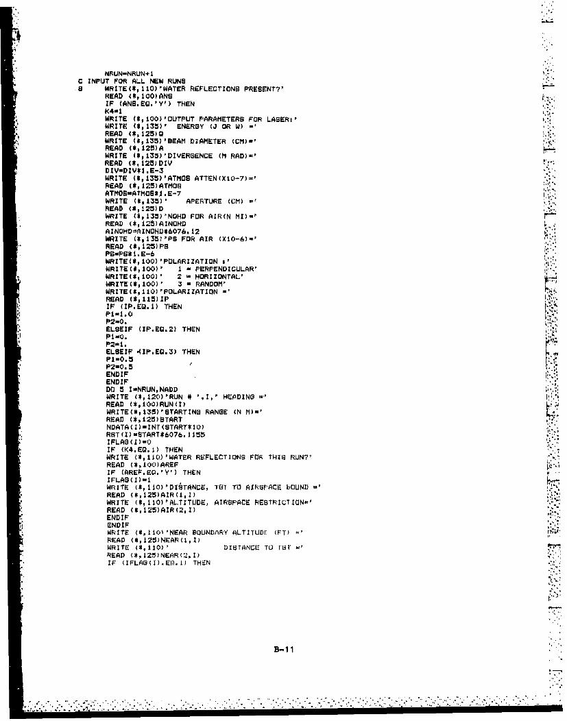
NRUNwNRUN+1C INPUT FOR ALL NEW RUNS.5 WRITE(*, 110) 'WATER REFLECTIONS PRESENT?'
READ (*,100)ANSIF (ANS.EW.'V9 ) THENK4=1 h'
& WRITE (*,100)'OUTPLJT PARAMETERS FOR LASERi'WRITE (*,l35)1 ENERGY (J OR W)-READ (*,125)QWRITE (*,135)'DEAM DIAMETER (CM)-'READ (*,125)AWRITE (*,135)'DIYERSENCE (M RAD)w'READ (*,125)DZYDZV-DZV*1 .E-3WRITE (*,135)'ATMOS ATTEN(XIO)-7)-'READ (*,125)ATMOSATMOS-ATMOS*. . E-7WRITE (*,135)' APERTURE (CM) -
READ (*.125)DWRITE (*,135)'NOHD FOR AIR(N MI)wlREAD (5, 12S)AINOHDLAINOHD=AZNOHV*607&. 12WRITE (*,1351'PS FOR AIR (XIO-6)-'READ (*,125)PSPS-PBS*1.EWRITE(*, 100) 'POLARIZATION aWRZTE(*, 100)' 1 - PERPENDICULAR'WRITE*, 100)' 2 w HORIZONTAL'WRITE(*,100)' 3 a RANDOM'WRZTE($,110) 'POLARIZATION -READ (S,115)XPIF (IP.Eg.1) THENP101.0P2-0.
*ELSEIF (IP.EG.2) THENP1-0. 2P2-I.ELSEIF $IP.EW.3) THENP1-0.5P2=0.5ENDIFENDIFDO 5 I-NRUNpNAODWRITE (*,120)'RUN * ',Ip' HEADING -1 IREAD (*,100)RUN(I)WRITE(*,135)'STARTING RANGE (N M)-'READ (*,125)STARTNDATAC I)-INT (STARTS 10)RST(I)-START*6076. 1155IFLAG(I)-0IF (K4.EQ.1) THENWRITE (*,IICIJ'WATER REFLECTIONS FOR THIS RUW'ýREAD (*,10CI')AREFIF (AREF.EQI.'Y') THENIFLAG(I)1lWRITE (10'D1tTANCE, TOT TO AIRSPACE LV0UND mREAD (*,125)AIR(1,I)WRITE (*,110)'ALTITLJDE, AIRSPACE RIESTRICTIONo'READ (*,125)AIR(2,I)ENDIFENDIFWRITE (*,110i'NEAR BOUNDARY ALTITUDE (FT) 17READ (*,125)NEAR(1,I)WRITE (5,110)' DISTANCE 'TO TGTREAD (*,12*)NEAR(Z2,I)IF (IFLAG(I).EQ.1) THEN
B-i11

FAR(2, I)mAIR(l, I)GOTO 5OEND IFWRITE (*,110)' FAR BOUNDARY ALTITUDE a
READ (*,125)FAR(1,I)WRITE (*,IlO)' DISTANCE TO TOTREAD (*,l25)FAR(2,I)
50 WRITE (*,110)' NEAR TOT ALTITUDE mpREAD (*,125)TAR(1,I)WRITE (2,110)' FAR TOT ALTITUDE a
READ (*,125)TAR(2,I)WRITE (*,±10)' TOT SEPERATION *
2"READ (*,125)TAR(3,I)WRITE (*.110)'NO OF PEAffS -
READ (*,115)NPEAKS(I)IF (NPEAKS(IkG8T.0) THENDO 6 JalNPEAKS(I)WRITE (*,IZOPOPEAI< ALTITUDE a'READ (*,125)PEARB(1,I,J)WRITE (*,110)'RANSE TO TOT -
READ (*,125)PEAKB(2,I,J)6 CONTINUE
ENDIFWRITE ~*10'SDATA CORRECT ?pREAD (* p1 CI) ANBIF (ANG.Eg.'N') THEN(30T0 7ENDIF
5 CONTINUE4 RETURNC WRITING TO A DATA FILE t41 OPEN (6pFILE-FNAME, STAT'US-' NEW' ,FORMN' UNFORMATTED')
WRITE(6)TITLEWRITE(6)UNNOHD,OF'NOHD, SUPWRITE (6)NRUNDO 42 I-1,NRUNWRITE (6)RUN (X)WRITE(6)NEAR(1, I),NEARC2, I) ,rAR(2,I) ,FAR(1, I)
* ~WRITE(6)TA-(1, I),TAR(2, I),TAR(3,I)WRITE(6)NF'EAKS(I)IF (NPEAKB(I).WT.C:U THEN
PDO 43 JwPAElWR'ITE (6)PEAK:S , I, 3) ,PEAKS (2, I, )
43 CONTINUEEND IFWRITE (6) NDATA ( )DO 44 J-1,NOATA(I)WRITE(6)LASER(I,2,3) ,LASER(I, 1,3)
44 CONTINUE42 CONTINUE
ENOFILE 6CLOSE (6, STATUS-'Rý:EEF")RETURN
100 FORMAT (A)105 FORMAT (3X,A)110 FORMAT (A0)115 FORMAT (BN,13)
'1120 FORMAT (A, I3,A*)125 FORMAT (F8.2)131') FORMAT (A,13,A,A)200 FORMAT (A)205 FORMAT (FS.2,EB.2)
4210 FORMAT an3215 FORMAT (VUS. 2)
*220 FORMAT (s FW cq*225 EORMAT e' mio P-ILL CONTrAINS S0Al O N ',A)
2Z' 3 FORMAT ('RUN # , 3 HAS ",A)*13b FORMAT' (.TX, A$)
ENS
B-12
'S.1

SBUROUTINE COMPt (NFRLIN, NADD, PS)C THIS SUBROUTINE COMPUTES MINIMUM ALTITUDE RESTRICTIONS r-ROM GIVEN RANGEC DATA
DIMENSION NEAR(2,1O),LASER(10,2,150),FAR(2,iO),TAR(3,10),RST(10)11PEAKS(2,10,10),NPEAKS(IO),NDATA(10),AIR(2,1 O),IFLAG(10),ALT(120)REAL NEAR,FAR,TAR,LASER,PEAKS,NOHD,DUF,NA,K1,K2,K3INTEGER NDATA,NRUN, NFEAKSCOMMON/REAfl/NEAR,FAR, TARE PEAKS, LASER, NDATA, NPEAKS, UNNOHD, OPNOHD,IBUF/COMP/AIR, IFLAG ,AINOHD,D,A,DIV,G,ATMOS,Pl,P2,RST
C OBAN LOWEST ALTITUDEB0A 30 IoNRUN,NADD
RS-RST C )SMALLmNEAR(l,I)IF (TAR(l,Ik.LT.SMALL) THENSMALLoTARCI, I) 1END IFIF (TAR(2,I).LT.SMALL) THENSMALL-TAR(2, I)ENDIF
A ~IF (FAR(1,I).LT.SMALL) THENSMALLuFAR C 1, )ENDIFDO 10 Jw1,NDATA(I)
C COMPUTE ALTITUDE RESTRICTION FROM NEAR BOUNDARY CONDI'(IONSAN-TAN (BUF)
f B~~N--NEAR(,1)-(AN*(NEAR±,i)+,rAR(1,1'))KiUTAR(i, I)*C-RS+NEAR(2, I))K2-NEAR(I,I)$(CAN*TAR(1,I))-RS)K3UAN*RS* CRS-NEAR(2. I))CNwKI-K2+K3KImBN**2K2w4*AN*CN
C IF FOLLOWING IS TRUE, NO BUFFER IS AVAILABLEIF (k2.GT.KI) THENNA--UNNOHD
C NO MORE CC1MPUTATION REQUIRED FOR THIS DISTANCESOTO 10EN I F
C ELSE COMPUTE ALTITUDE RESTRICTION,NEAR BOUNDARYC O ARGET I(S AVAkIADLE (2AN
CIF PEAKS PRESENT, INSURE BUFFER IS AVAILABLE OVER PEAK AND LINE OF SISHT
IF (NPEAKS(I).ST.Q) r'HENDO 20 K*1,NPEAI<S(I)I F (RS. ST. PAKB(2,1, K) ) THE~N
K2m(SQRT(Ki))*ANK'3uNA-(PEAKS(1, I,K.)+K2)Xm (RS-PEAKS (1,1, K)) /K3rESTw (RS--NPAR (2, 1))(NA-NEAR (1,I'1
C IF' THIS IS FALSE, THEN ADEQUATE CLEAR~AN'CE BY NEAR L40UNDARY ALTITUDE ISC AVAILAB~LE
IF' (X.LT.TEsr) THENKI- (RS*FIEAKB (I, I, K) )- (NEAR (2, 1) *PEAK'i3 (1±, 1, k)
K3wKI-K2MAnK3/ (PEAKS (2, 1 K) -NEAR (2,!1)ENDI FENL)LF
B-13
,~ ~~ a,
-. -iii

20 CONTINUEENDIF
C DETERMINE IF HYPOTENUSE IS LESS THEN OPTICS NOHDTEST-SORT ( ((RS+TAR(3, I +FAR (2,1)) **2). C(NA-FAR( 1,I))*)
C IF IT IS LESS, THEN COMPUTE ALTITUDE RESTRICTION FOR FAR B'OUNDARY
KU-1
IRUNwOIF (TEST. ST. OPNOHD) THENSOTO 6END IF
C IF RErLECTIONS ARE PRESENT THEN 130 TO PART TWOIF (IFLASCI).Eg.1) THENGOTO 2ENDIF
C IF NOT THEN COMPUTE ALTITUDE FOR BUFFERRFARmFAR(2,I)K1-RS+TAR (3,, I) 4FAR (2, I)K2-RS+TAF%(3, I)SF.k2-Kl-(TAR(2,I)*AN)-(FAR(1,I)*AN)K3ini:*TAR(2,Z))+(Kl*K2*AN)-(FAR~IC,I)*K'2)CF-K3+(FAR(2, I)*TAFR(2, I)*AN)K I3F * *2K2-4*AN*CF
C IF THE FOLLOWING IS TRUE THEN NO BUFFER EXISTSIF (K2.GT.Ki) THEN
04 NAw-UNNOHDC NO FARTHER CALCULATION IS REQlUIRED FOR THIS DISTANCE
S~OTO 40C ENfl IF
COTHERWISE CALCULATE FAR BOUNDARY ALTITUDE RESTRICTIONSFA-(-SF-(SORT((DF**2)*-44*AN*eFC )))/(2*AN)IF (IFLAS(I)sEQ.0) THENGOTO ZENDIF
C WATER REFLECTIONS ARE INVOLVEDC SET ALL DISTANCES TO CM AND ESTABLISH AN INITIAL ALTITUDE2. R3wRS*30.48
* ~RI-5C'CI. *30. 48RHi-iOCI. *30. 40RL-0.TR-TAR (3,I) *3l. 4STA-TAR (2, I)*30.48IF (TA.GT.R1) THENRI-TA
.Y., ENDIFC FIND DISTANCE FROM TARGET TO MAINTAIN THE BUrFER
I THETA-BUF+(ATAN((R3+TR)/(Ri-'TAC)))RFAR- (Ri* (TAN(THETA)))-(RZ.+TR)A2-Ai-RFARvR2-A2/(TAN(THETA))
C NOW DETERMINE THE ENERGY AT THE BOUNDARYDIST- (Ri+R2)/'(COS(THETA))E N-2. 6* Q* ( I-(E XFP(- D * *2)((A + (1) S T* DIYV) )*2)REDATwEXP C-ATMOS**DIST)THEPR-ASIN((8IN(THETA)/1.325)REDAN-Pi*U(SIN(THETA-THEFPR))**2)/( (SIN(T'HE-TA+TIHEFR))**2) 9
REDi-P2*( (TAN(THETA-THEPR))**2)/((TAN(THETA4+THEPR))**2-)EN-EN* (REDAN+REDI)C*REDATIF (EN.t3T.PS) THENRL-Rl
S3OTO 1ELSE IF (EN. LT. (C).t*P) THENRH-Ri
B-1 4

Rin(Rl+RL) /2.IF (RI.LE.TA) THENRlr*TASOTO 5ENDIF t'GOTO IENDIFIF (R2.GT.(AINOHD*30.4e)) THEN
12 RI-Rl+(50.*30.4S)THETA=BUF+ (ATAN C(R3+TR) /(RI-r.?))RFARu(Rl*(TANCTHETA)))-(R3*.-.A',A2mAlI-RFARR2nA2/ (TAN (THETA)) ~IF (R2.GT.(AINOHD*30.4S)) THENGOTO 12ENDIFENDIF
5 FA-RI/30.4eSOTO 3
4 NAw-UNNOHOSOTO 40
C NOW COMPARE WITH NEAR BOUNDARY REsTRICTIONS AND OBTAIN HIGHESTs IF (FA.GT.NA) THEN
NAmFAENDIF
*C IF THIS 18 LESS THEN THE MINIMUM ALTITUDE THE RANGE CONTAINS THEN USEC THAT MINIMUM6 IF (NA.LT.8MALL) THEN
NAwSMALLENDIF
C NOW SET ARRAY VARIABLES E(WUAL TO THE COMPUTED VALUES40 LASER(I,IJ)mNA
LASER(1,2,J)*'RgRS-RS-607. &I
10 CONTINUE30 CONTINUE
RETrURNEND
I Il
B-i15

SUBROUTINE PRINT(I, ING)t DIMENSION NEAR(2,1O),LASER(1O,2,15ObFAR(2,10),TAR(3,1O),IPEAKS(2,IO,IC'),NPEAKS(1O),NDATA(1O),RUN(ILi)CHARACTER TITI.E*20, RUNS2Q, A*lREAL NEAR, FAR, TAR,LASER,PEAKSNOHD, BUF, INCI ~INTEGER NDATA,NPEAKS,FNUM, NADD,II, NPR, NREC
490 COMMON/READ/NEAR, FAR, TAR, PEAKS, LASER, NOATA, NPEAKS,UNNOHD,OPNOHD,'t" ~ IBUF/CHAR/TITLE,RUN V
WRITE(*, (A)')'SUDROUTINE PRINT'C THIS SUBROUTINE SENDS DATA TO THE PRINTER
CSTOPEN(6,ILEwIPRINTERil)CSTTAB FOR MAIN TITLE
WRITE (6,210)CLOSE (6)OPEN (6,FILE-'PRINTERu ',FORM-'UNFORMATTED')
C SET DOUBLE SIZE MODE
C RETURN3CRRIG~ E?2
C SET TO STANDARD LETTER SIZE
WRITE(6) 149I ~CLOSE (6)OPEN (6,FILE-'PRINTERm ,rORM-'FORMATTED')
C LINE FEEDWRITE (6,290)CLOSE (6)OPEN (6,FILE'lPRINWERa',FORMw'UNFORMATTED')
C SET TO DOUDLE SIZE MODEWRITE(6) 14WRITE (6) RUNQ()
CSET TO STANDARD LETTER SIZEWRITE(6) 149 VCLOBE(6)OPEN(6,FILE-'PRINTERm' ,FORM-'FORMATTED')
C LINE FEEDWRITE(6,215)WRITE(6, 105)
C SET NOHDIS TO NAUTICAL MILESXi-UNNOHD/6076. 12X2OaPNOHD/6076. 12
CSE? BUFFER ANGLE TO MILLIRADIANSYwDUF/. 001
C WRITE NOHD'S AND SUFFER ANGLE
IF (X1.EQ.X2) THEN
.4 WRITE(6,1iS)YIXIWRITE(6,1105)X
.1 WRITE(6,12')Y
WRITE (6, 105)C WRITE FEAR BOUNDARY PARAMETERS
WRITE(6, 135)
B-1 6
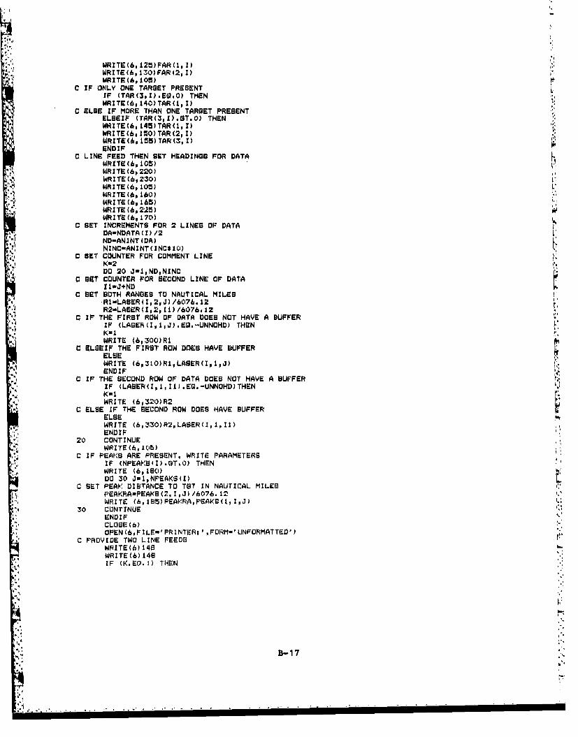
WRITE(6,125)FAR(1,l)WRITE (6,130) FAR (2, I)WRITE(6,105)
C IF ONLY ONE TARGET PRESENTIF (TAR(3,I).Eg.0) THENWRITE(6, 140)TAR(1, I)
C ELSE IF MORE THAN ONE TARGET PRESENTELBEIF (TAR(3,I).ST.0) THENWRITE(A, 145)TAR(l, I)WRITE(6, 10) TAR (2, I)WRITE(6, 155)TAR (3, I)ENDIF
C LINE FEED THEN SET HEADINGS FOR DATAWRITE(6, 105)WRITE Cb,220)WRITE(6,230)WRITE (6, 105) LWRITE(6, 160)
*WR ITE (6, 1615)W'RITE (6, 225)WRITE (6, 170)
C SET INCREMENTS. FOR 2 LINES OF DATADA-NDATA(I)/2ND-ANINT(VA)NINC-ANINTt INC* 10)
C SET COUNTER FOR COMMENT LINEKw2DO 20 3u1,NDpNINC
C SET COUNTER FOR SECOND LINE OF DATAI 1-J+ND
C SET BOTH RANGES TO NAUTICAL MILES-Rl'.LAUER(1,2pJ)/6076.12R2wLASER(Iw2oI1)/6076.12
0 IF THE FIRST ROW OF DATA DOES NOT HAVE A BUFFERIF (LASER(I,1,J3).EW.-UNNOHD) THEN
4~) iKu1WRITE (6,300)RI
C ELSEIF THE FIRST ROW DOES HAVE BUFFERELSEWRITE (6,310)Rl,LASER(I,1,J)
C IF THE SECOND ROW OF DATA DOES NOT HAVE A BUFFERIF (LASER(Z, 1,11).EQ.-UNNOHD)THEN
LEWRITE (6,320)R2C LEIF THE SECOND ROW DOES HAVE BUFFER
WRITE (6,-330)R2,LASER(I,1,I1)ENDIF
20 CONTINUEWR ITE (6, 11:1)
C IF PEAKS5 ARE PRESENT, WRITE PARAMETERSIF (NPEAKB(I).GT.0) THENWRITE (6,19o)DO 30 Jw1,NPEAKS,(I)
C SET PEAK' DISTANCE TO TGT IN NAUTrICAL MILESPEK~mEKS21,3) /6076. ±2WRITE (,185)PEAIKRA,FEAIKW(l,I,3)
30 CONTINUEENDIFCLOSE (6)OPEN(6,FIl-E-'FRINTERi ',FORM-'UNFORMATTED')
C PROVIDE TWO LINE FEEDSWRITE(6) 148WRITE(6) 148IF (K. E0. 1) THEN
B-i17

WRIT(6)1*** NO BUFFER AVAILABLE'ENDIFWRITEW()12L'LOSE (6RETURN
100 FORMAT(5X,A)105 FORMAT('')
* . 110 F'ORMAT(2X,'NOHD (UJNAIDEDl VILWINS)-*.,Fl3.2,I N4M') .
112 FORMATC2X,'NOHD (VIEWZI't I /S;,F. NMI)115 FORMATC'BUFFER *',F7.$. Pf RAriTANS')120 FORMATC'NEAR BOUNDARY I)125 FORMATC5X,IALTITUDE (MC-.) *',FB.O,' FT 1)130 FORMAT(4X,'DISTANCE IQ, TOT r'l,F8.0,' FTI)135 FORMAT('FAR BOUNDARY'.140 FORMAT('TARGET ALl'I.UDL~ *',FS.O,I FT MSL,')145 FORMAT('NEAR TARGET ALTITUDE -',FS.Op' FT MSLI)150 FORMAT('FAR TARGET ALTITUDE -',FS.O,' FT MSL')155 FORMAT('TARGET BEPERATION -',FI.Op' FTI)160 FORMAT(5X,'DIBTANCE',SXw'ALTITLDOE',LOXp'DISTANCE',5X,'ALTITUDE')185 FORMAT(8X,'TO TGT',BX,'(FT)',13X,'TO TGT'1 9X,I(FT)')170 FORMAT(5X, ----------- 5X,---------- LOX,'----------- 5X t- -- -- - - ---P)175 FORMAT( 1XF10. 2o7X, F7.0,"7X, FIO.2,6XF7.0)190 FORMAT('FEAKS ALQN~q FLIGHT LINE')195 FORMAT('DISTANCE TO TGT m-'FF.2,1 N M'p5X,IALTITUDE -1,FS.2p! FT')190 FORMAT(A)195 FORMAT('INCREMENTS 40.1,1D.Zl.0) ml$)
1200 FORMAT(F4.1)205 FORMAT(I3)210 FORMAT(20X,S)
*215 FORMAT(l)220 FORMAT(20X,'HINIMUM FLIGHT PROFILE DATA')225 FORMAT(6X,I(N M)',l0X,IMSL',14X~p(N M)',1()X,'MSL')
4 * 290 FORMAT(20X,*)300 FORMATC1XF10i.2p7Xpl*******'*)
* 310 FORMAT(1X,F10.2,7XF7.0*).320 FORMAT(7X,P10.2,6X,'*S*S***')330 FQRMAT(7XIFIO.2,6X,F7.0)
END
B:11

"IKREAO No OPTIONSNITNOPINI RAD DATA PIl DI OLY I RNT ALL RUNS*ADDATA ANDDDAT * PRINT SELECTED NUNS3 No Disk INPUT 3 - NO PAINTER OUTPUT
INPUT NRo? INPUT PUPlINNADING PFRINTER
Is Ropy No Is POP? No
INPUT DATA IINCO - INTISOFPILE NAME 0ISTANCE .. PRON.2 LAIN"
To TOT TO , IN ' INTOD
DISK WRITING OPTIONS$E D*O.WR'IT TO DATA PIL NAOSNTSNN 01,0INO DiSk OUTpuT OATA USING DISKS
IRNITING CALL DISK READINGOPTION) BumROIJIIN DISKS
ISOP NO3 11POT60
INPUT DATAPILE NAME
PONWm NITING
SN"OPT I sNORT SONS
tons ICOMPI.ITSA IUweNSFOR IIIAm 1010 IT - NIN NWI T"N AOD
ALTITE NS0R101,111 ITOYAL NO, OP NUNS TOA OF OP USUSING CONU SUN OUTINI INPUT PROM ATA FILEI IUN IATAM P05
ISWOPNUN AGOYIDCNINU.U NUNS, NOD
OSOR I UTLS
a UNROUTINK IsOPN1D
UIROPTIN I 'sNTomeSS
ADiIDUNI 'UNINGHAN
1,U TITLES
I As
MNUN NATA AND ATR
B- 19

TABLE OF VARIABLES IN MAIN PROGRAM
ROPT Read options. The value of ROPT would determine whether the datafile was to be read from the disk, whether any runs were to beadded, or if it is a new data file. s
WePT Write option. The value of WOPT will determine if the data is to bewritten to a data file on the disk.
POPT Printer options. This will determine whether all runs are to beprinted, whether selected runs are to be printed, or no printeroutput.
FNAMR Data File name to be read from the disk.i
FNAMW Data File name to which the run data and minimum flight profilespreviously computed are to be written.
INC Increments of ranges (laser to target) in nautical miles that is tobe printed on the minimum flight profile table.
DISKR Subroutine that reads run data and minimum flight profile altitudesfrom data file FNAMR, prompts for run data for new data files orexisting data files, and outputs ALL RUN data and correspondingminimum flight profile to data file FNAMW.s
RIRT Number of runs that already exists in data file prior to adding anyrune.,
NRUN Number of rurs input from data file.
NADD Number of now runs or addition runs to existing runs input from data
RUN Title of each run.s
NPRINT Number of runs for output to the printer.
RPRINT The run number to be printed.
COMPU Subroutine for computation of minimum flight altitudes for run datathat has not been read from an existing data file.
K3 Selects whether subroutine DISKR is to be used for reading data fileor creating a data file-
BI
fl-2 0 •-

2ABLk" OF VARIABLES IN SUBROUTINE DISKR
TITLE Title of data file that resides in either FNAMW or FNAMR. This isthe title that will be printed as the main heading on the printeroutput.
.1; LUNNOHD This is the NOHW for the laser system to be used on the range beingevaluated for unaided intrabeam viewing.
OPNOHD This is the NOHD for this laser system for intrabeam viewing using
optical devices.
BUF One-half the buffer angle for the type of laser to be used.
NRUN The run number for selected run printout.
RUN Title of each individual run. This can either be different headingsfor the laser aircraft, different range parameters or targetlocations.
NEAR(1, Altitude of the range boundary closest to the lasing aircraftexpressed in feet relative to mean sea level
NEAR(2, Distance from the target to the range boundary closest to theaircraft.
FAR(1, Altitude of the range boundary farthest from the lasing aircraftexpressed in feet relative to mean sea level
FARM2, Distance from the target to the range boundary farthest from theaircraft.
*TAR(1 Target altitude relative to mean sea level for the target closest tothe lasing aircraft.
TAR(2, Target altitude relative to mean sea level for the targnt farthest
from the lasing aircraft
TAR(3, Target separation. This is zero when only one target is present.
NPEAKS Number of terrain peaks along the aircraft flight line that are to beconsidered
PEAKS(1, Altitude of the peak relative mean sea level
PEAKS(2, Distance that the peak is from the closest target
B-21
! ".4 .. ..... ...... . .
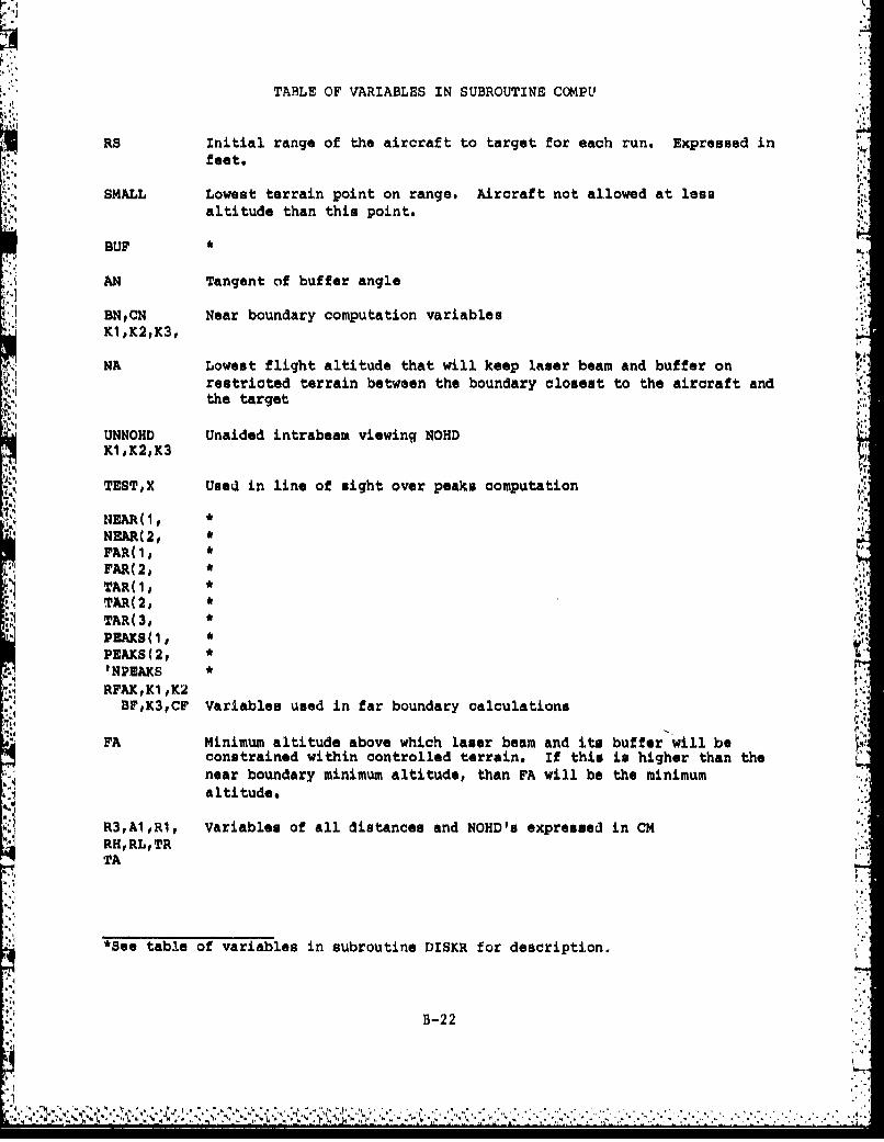
TABLE OF VARIABLES IN SUBROUTINE COMPU
RS Initial range of the aircraft to target for each run. Expressed infeet.
SMALL Lowest terrain point on range. Aircraft not allowed at lessaltitude than this point.
BUF *
AN Tangent of buffer angle
BNCN Near boundary computation variablesIK1,K2,K3,
NA Lowest flight altitude that will keep laser beam and buffer onrestricted terrain between the boundary closest to the aircraft andthe target
3,:4
UNNOHD Unaided intrabeam viewing NOHDKIK2,K3
TEST,X Used in line of sight over peaks computation
NEAR(1, *
NEAR(2, *
FAR(2,TAR(I, *TAR(2, *
TAR(3, *
PEAKS(I, *"
PEAS(2, *
I.NPEAKS * .44
RFAK,K1,K2BF,K3,CF Variables used in far boundary calculations
FA Minimum altitude above which laser beam and its buffer will beconstrained within controlled terrain. if this is higher than thenear boundary minimum altitude, than FA will be the minimumaltitude.
R3,A1,R1, Variables of all distances and NOHD's expressed in CMRH,RL,TRTA
*See table of variables in subroutine DISKR for description..
B-22

,10
TABLE OF VARIABLES IN SUBROUTINE COMPU (CONTINUED)
THETA, A2 Variables used in reflection calculationsR2,
DIST Altitudes of viewing aircraft and lasing aircraft
REDAT Reduction of energy due to atmospheric attenuation
REDAN, REDI Reduction of energy for horizontal and vertical reflectioncoefficients, respectively
EN Energy at viewing aircraft
AINOHD Single pulse NOHD for aircraft crew unaided intrabeam viewing
LASER(,1 Minimum altitude of lasing aircraft where laser beam will beconstrained within either controlled range boundaries orrestricted airspace
LASER(,2 Corresponding range to target of lasing aircraft for which laser-(1I applies
%4
B-23
I'7!

DISTRIBUTION
4.1
ATNNaval Electronics Systems CommandATTNt 01K 'jWazhington, DC 20360 (2)
U. S. Army Environmental Hygiene AgencyATTNt HSE-RLAberdeen Proving Ground, MD 21010 (2)
Fleet Analysis Center (3)ATTNt 8523Naval Weapons Station, Seal BeachCorona, CA 91720
Local_
N41 (15)3431 (10)
i"
a'
A:, 'A
has"-
4 -,
4 4 4 44 * .. , 4
ft 4 - 4-4 4 4.4
444 *4.. ,4 . 4*44 4 . . ... . .
'4 .4 'W . 4 . 4 . ~ * I 4 . , 4 4 4 - 4... . . . . . . .. 4 ',