Embed Size (px)
Citation preview

Konvekta AG Am Nordbahnhof 5 34613 Schwalmstadt Germany ✆ +49 ( 0 ) 66 91 / 76 – 0 � +49 ( 0 ) 66 91 / 76 - 200 � [email protected] www.konvekta.com
Operating and maintenance
instructions KONVEKTA air conditioning unit
KL85T
SCANIA HIGER Touring
With controller KS410
Type:
• R134a
• 24 Volt DC
ID#:BBA-KL60T12AK Version: A02
BAKL60T12AK Edition: 15.05.2012 Page: 2/31
Contents
Page:
• Introduction ......................................................................................................................... 4
• Information on the operating instructions ........................................................................ 5
1. Directives for installation, connection and use ............................................................. 6
2. Overview KONVEKTA thermo system in SCANIA HIGER A80 ...................................... 7
3. Technical data .................................................................................................................. 7
3.1. Air conditioning unit............................................................................................................ 8
3.2. Frontbox ............................................................................................................................ 8
3.3. Pressure Switch ................................................................................................................. 8
3.4. Compressors ..................................................................................................................... 8
3.4.1. Type KVX40/470-655 .................................................................................................... 8
4. Intended use ..................................................................................................................... 9
5. Generally information for a/c unit ................................................................................... 9
5.1. Operating Conditions ......................................................................................................... 9
5.2. General notes on controller KS410 .................................................................................... 9
6. Operation ........................................................................................................................ 10
6.1. Description keys driver’s seat .......................................................................................... 10
7. Description keys passenger compartment .................................................................. 11
7.1. Time adjustment .............................................................................................................. 13
7.2. Adjust starting time of the additional heating .................................................................... 13
7.3. Read trouble memory ...................................................................................................... 14
8. Error codes KS 410-NC ................................................................................................. 14
8.1. Sensor error: .................................................................................................................... 14
8.2. Response: ....................................................................................................................... 14
8.3. Potentiometer response: .................................................................................................. 15
8.4. Digital outputs (DA): ......................................................................................................... 15
8.5. Webasto error message auxiliary heating device: ............................................................ 15
9. Maintenance / Service ................................................................................................... 16
9.1. Maintenance schedule for air conditioning system KL85T ................................................ 16
9.2. Legend to the maintenance schedule .............................................................................. 17
9.2.1. Check charging level of the refrigerant system at the sight glass (item 1) .................... 18
9.2.2. Check oil level of the compressor (point 2) .................................................................. 18
9.2.3. Operation test of the high pressure switch (point 3) ..................................................... 18
9.2.4. Operation test of low pressure switch (point 4) ............................................................ 19
9.2.5. Operation test of HP and LP switch (points 3 + 4) ....................................................... 20
9.2.6. Replacement of filter drier (point 5) ............................................................................. 20
9.2.7. Ckeck condenser and and evaporator battery for contamination (point 6) ................... 20
9.2.8. Check refrigerant receiver ........................................................................................... 20
9.2.9. Check filter for contamination, replace if necessary ..................................................... 21
9.2.10. Operation test of the air flaps (point 9)......................................................................... 21
BAKL60T12AK Edition: 15.05.2012 Page: 3/31
9.2.11. Operation test of condenser fan (point 10) .................................................................. 21
9.2.12. Operation test of evaporator blowers (point 11) ........................................................... 21
9.2.13. Check condensed water drains (point 12) ................................................................... 22
9.2.14. Check refrigerant pipes/hoses for leak tightness and firm seat (point 13) .................... 22
9.2.15. Check heating lines for leak tightness and firm seat (point 14) .................................... 23
9.2.16. Operation and leak tightness test of water valves ( point 15) ....................................... 23
9.2.17. Exchange compressor oil charging (point 16) .............................................................. 24
9.2.18. Check screw connections at compressor and compressor bracket (point 17) .............. 24
9.2.19. Check tension and condition of V-belt (points 18 + 19) ................................................ 24
9.2.20. Operation test and firm seat check of temperature sensors and (point 20) .................. 25
9.2.21. Check plug connections and fuses (point 21) .............................................................. 27
9.2.22. Check heating perfomance (point 22) .......................................................................... 28
9.2.23. Check cooling perfomance (point 23) .......................................................................... 29
9.2.24. Fresh air / recirculating air filter ................................................................................... 29
9.2.25. Condenser battery ....................................................................................................... 29
9.3. Troubleshooting ............................................................................................................... 30
10. Warranty Conditions ...................................................................................................... 30
11. Waste disposal in accordance with legal provisions .................................................. 31
12. History of modification .................................................................................................. 31
Appendix:
� Maintenance Schedule Bus WP07050618
BAKL60T12AK Edition: 15.05.2012 Page: 4/31
Introduction
These operating instructions have been written for drivers, operators and the maintenance staff of your air conditioning unit.
In this context, we refer implicitly to the compliance with our general installation guidelines. These can be obtained from the KONVEKTA technical after sales service: [email protected].
Please observe our valid safety instructions, available under www.konvekta.de/asv.html. In case of order placement or any other conclusion of contract the safety instructions get in-tegral part of the contract.
These operating instructions have to be read carefully and made use of before the first start-up and after that regularly by each person who is involved in handling the machine:
• Operation including troubleshooting and waste disposal of fuels and auxiliary agents.
• Servicing, inspection, repair
• Transport
This facilitates the handling and avoids trouble caused by improper operation. Working in compli-ance with these operating instructions increases operation reliability and service life of the air con-
ditioning unit and reduces life cycle costs.
Please complete these instructions by adding the national provi-sions for prevention of accidents and environmental protection.
These instructions are part of the air conditioning unit. Always have a copy at hand in the driver’s cabin.
You will certainly understand that we will not recognize any warranty claims due to improper han-dling, inadequate maintenance, applications that do not correspond with the determined use, utili-zation of none-admitted fuels or the non-observance of safety provisions. KONVEKTA will annul without prior notice all obligations concerning guarantee, service contracts etc. regardless if granted by KONVEKTA or its distributors in case other than original KONVEKTA spare parts or parts bought from KONVEKTA AG have been used for maintenance and repair. These operating instructions contain all necessary information to operate your air conditioning unit. In case you need more explanations, please contact the next KONVEKTA service station�.
� On our website www.konvekta.com in category >service< you will find a survey of contact details of all our service partners close to your location.

BAKL60T12AK Edition: 15.05.2012 Page: 5/31
Information on the operating instructions
These operating instructions are valid for the a/c-units type:
� KL 85T
When taking the unit into operation we recommend adding the following data. This will also be important for your orders of spare parts, and in case of warranty.
Serial number of the unit: ..................................................
Order No.: A /: ..................................................
Year of construction: .................................................. (MM/JJ)
Date of first operation: .................................................. (TT/MM/JJ)
The machine is in accordance with the EC machinery directive 2006/42/EC.
The unit contains or needs fluorinated greenhouse gas for operation and is subject to identification requirements in accordance with F-Gas Regulation 517/2014.
Due to the fact that scope of supply depends on the order, equipment of your product may differ in some parts of description.
In case your product is equipped with details not shown or described in the operating in-struction, your KONVEKTA Service Station will always be at disposal for informing you about correct operation.
In the course of further developments we reserve the right to technical modifications without prior notice. Warranty and liability conditions of KONVEKTA AG’s general business conditions are not enlarged by the above notes.
Indications and photos should neither be copied and circulated nor used for competitor’s purposes. All rights according to the copyright remain expressly reserved.
Manufacturer: KONVEKTA AG, P.O. Box 2280, D-34607 Schwalmstadt

BAKL60T12AK Edition: 15.05.2012 Page: 6/31
1. Directives for installation, connection and use
Please read the following instructions carefully before installing, connecting and operating the de-vice. We assume no liability for incorrect handling and usage.
WARNING
CAUTION
MAKE THE CORRECT CONNECTIONS. Failure to make the proper connections may result in fire or product damage.
USE ONLY SUITABLE VOLTAGE. The usage with an unsuitable voltage may result in fire. In addition, an unsuitable voltage may result in failure or product damage.
ENSURE THAT THE WIRES ARE NOT CARRY-ING CURRENT WHILE CONNECTING. Connecting wires which carry current may result in electrical shorts or product damage.
ONLY USE WIRES WITH SUFFICIENTLY LARGE CROSS SECTIONS. Using wires with insufficiently large cross sections will exceed the current carrying capacity of the wires and result in fire or electric shock.
DO NOT DISASSEMBLE OR ALTER. Doing so may result in an accident, fire or electric shock.
DO NOT INSTALL IN LOCATIONS WHICH MIGHT HINDER VEHICLE OPERATIONS. Doing so may obstruct forward vision or hamper movement and result in serious accident.
DO NOT BLOCK VENTS OR RADIATOR PAN-ELS. Doing so may cause heat to build up inside and may result in fire.
USE THE CORRECT AMPERE RATING WHEN REPLACING FUSES. Failure to do so may result in fire or electric shock.
DO NOT PLACE HANDS, FINGERS OR FOR-EIGN OBJECTS IN INSERTION SLOTS OR GAPS. Doing so may result in personal injury or damage to the product.
AVOID SEVERE IMPACTS. Do not expose the device to severe impacts or blows. Doing so may result in product damage.
HAVE THE WIRING AND INSTALLATION DONE BY EXPERTS. The wiring and installation of this device requires special technical skills and experience and must be conducted by experts.
ARRANGE THE WIRING SO IT IS NOT CRIMPED OR PINCHED BY A SHARP METAL EDGE. Arrange the wiring so it will not be damaged.
DO NOT INSTALL IN LOCATIONS WITH A GREAT DEAL OF MOISTURE OR DUST. Avoid installing the device in locations with incidence great deal of moisture or dust. Moisture or dust that enters this device may result in product failure or damage.
USE SPECIFIED ACCESSORY PARTS AND IN-STALL THEM SECURELY. Be sure to use the specified accessory parts. Use of other than designated parts may damage this device internally or may render it unsafe to install and use.
CEASE USE IMMEDIATELY IF A PROBLEM OC-CURS. Failure to do so may cause personal injury or dam-age to the product. Return it to your authorised cus-tomer service.
TEMPERATURE. Be sure the environmental temperature is in the al-lowed range before turning the device on.
USE DEVICE ONLY FOR THE SPECIFIED APPLI-CATION AREA. Using the device for another purpose or in another application area than the intended one may result failure, product damage or injury.
PRODUCT CLEANING. Use a soft dry cloth for cleaning the device. For more severe dirt, please dampen the cloth with water only. Anything else has the chance of damage the product.
Scope of these guidelines. These guidelines apply for all devices which are pro-duced and/or marketed by the above manufacturer.
Transport terms Handle the unit with care at all times. During transport make sure that the unit is stored safely and cannot be damaged. If more than one unit is trans-ported, every unit has to be packed singly to avoid the units damaging one another. The carrier is liable for all damages during transport.
BAKL60T12AK Edition: 15.05.2012 Page: 7/31
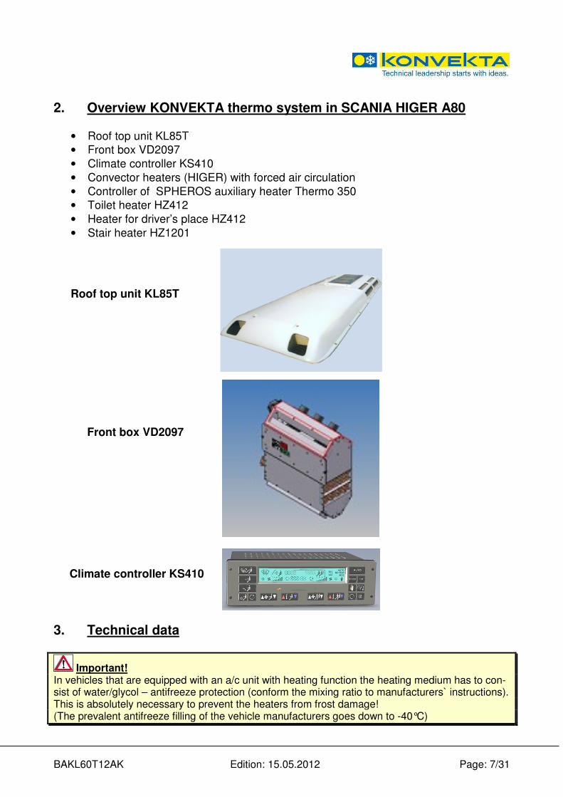
2. Overview KONVEKTA thermo system in SCANIA HIGER A80
• Roof top unit KL85T
• Front box VD2097
• Climate controller KS410
• Convector heaters (HIGER) with forced air circulation
• Controller of SPHEROS auxiliary heater Thermo 350
• Toilet heater HZ412
• Heater for driver’s place HZ412
• Stair heater HZ1201
Roof top unit KL85T
Front box VD2097
Climate controller KS410
3. Technical data
Important! In vehicles that are equipped with an a/c unit with heating function the heating medium has to con-sist of water/glycol – antifreeze protection (conform the mixing ratio to manufacturers` instructions). This is absolutely necessary to prevent the heaters from frost damage! (The prevalent antifreeze filling of the vehicle manufacturers goes down to -40°C)

BAKL60T12AK Edition: 15.05.2012 Page: 8/31
3.1. Air conditioning unit
Type KL85T
Operating voltage [V] 24
Refrigerant Typ R134a
-quantity approx [kg] 10
GWP 1.430
Current consumption [A] 95
Cooling capacity at +50°C [W] 38.000
Heater output Q=100 [W] 45.000
Air volume [m3/h] 6.600
Measurements:
- length [mm] 4.545
-width [mm] 1.892
- hight [mm] 185
Weight of unit approx.: [kg] 220
3.2. Frontbox
Cooling capacity [W] 7200
Heating capacity [W] 20.000
Air volume [m³/h] 1.092
Current consumption [V / A] 26 / 16
3.3. Pressure Switch
Low pressure switch 0,3 ± 0,1 off 2,1 ± 0,2 on
High pressure switch 25,5 ± 0,5 off 18,0 ± 1,0 on
3.4. Compressors
Important: To avoid leakages at the shaft seal of the compressor: The compressor should be started every 4 weeks for approx. 15 minutes! This also applies when the vehicle is not into operation for a longer period or when the air condi-tioning unit is not used!
� Compressor type depending on scope of delivery, see identification plate at compressor.
3.4.1. Type KVX40/470-655
Compressor Type KVX40/470 KVX40/560 KVX40/655
Weight 1) 35 kg 35 kg 35 kg
Oil brand / quantity (litres) Esteröl SE55/2 Esteröl SE55/2 Esteröl SE55/2
Magnetic clutch2) 24V DC 24V DC 24V DC
BAKL60T12AK Edition: 15.05.2012 Page: 9/31
4. Intended use
The KONVEKTA air conditioning unit is an air conditioning system that works with the ozone friendly refrigerant R134a and which creates a pleasant and individually adjustable room tempera-ture by means of forced convection. The determined use includes also the observance of the oper-ating instructions as well as the proof of regular inspections.
5. Generally information for a/c unit
Attention in case of roof top a/c units: Never switch on the a/c unit during car-wash!
− The air conditioning unit is operational with running engine only.
− At cooling operation the humidity inside the vehicle is decreased, which avoids steamed-up windows.
− The air conditioning unit works most effectively with windows and doors shut. If, however, the interior of the standing vehicle has been heated up severely by exposure to sunlight, short-time opening of windows/doors may accelerate the cooling down process.
− At high outside temperature and humidity, condensate might drip off the evaporator and make a puddle under the vehicle. This is quite normal and no sign for a leakage.
− The filter in the return air grid (optional) retains contaminants. If the outside air is contaminated with gas, switch over to return air operation. The filter should be cleaned or replaced respective-ly on a regular basis so that the capacity of the a/c unit is not affected.
− If you think that the air conditioning unit has been damaged switch it off immediately in order to avoid further damage. The air conditioning unit may be taken into operation again only after it has been checked at a KONVEKTA Service Station.
5.1. Operating Conditions
NOTE: KONVEKTA uses components made of copper and aluminium, which last a whole unit lifetime un-der normal environmental conditions. Should the units be operated under aggressive environmen-tal conditions, i.e. air containing salt-, phosphate- or ammoniac extremely, a corrosion of the cup-per- and aluminium components cannot be ruled out. The cupper- and aluminium components of the KONVEKTA systems are not suitable for such extreme application conditions. We indicate em-phatically, that corrosion is not subject to warranties for defects. KONVEKTA does not take over any warranties for defect, neither for corrosion nor for consequential damage resulting there from, nor for damages caused by cleaning the systems with highly compressed or corrosion advancing substances.
5.2. General notes on controller KS410
KS410 is an easy to handle control unit for air conditioning systems in modern coaches. The sim-ple and well-arranged operation of this unit relieves the driver from all questions regarding the op-timal air conditioning of the passengers’ compartment. The control unit is connected with the original instrument-panel illumination of the vehicle. This means that if vehicle illumination is turned on also the night illumination of the control unit is acti-vated.
Self-test After switching on the control unit runs a self-test. After self-test time, actual temperatures are shown in the display.
BAKL60T12AK Edition: 15.05.2012 Page: 10/31
6. Operation
Danger of accidents! - Focussing your attention on the road traffic is of top priority
- Only operate your air conditioning unit when the traffic situation allows it
- Make sure you can clearly recognize and read all operation and display elements at any time
- Protect all displays against irritating sun glare and any other optical disturbances
- Please note that the control panel keys have not been designed for heavy stressing
- Excessive or fast pressing of the keys for adjusting the set temperature does not accelerate the cooling down process. It possibly damages the control panel and so affects the general perfor-mance of the air-conditioning unit
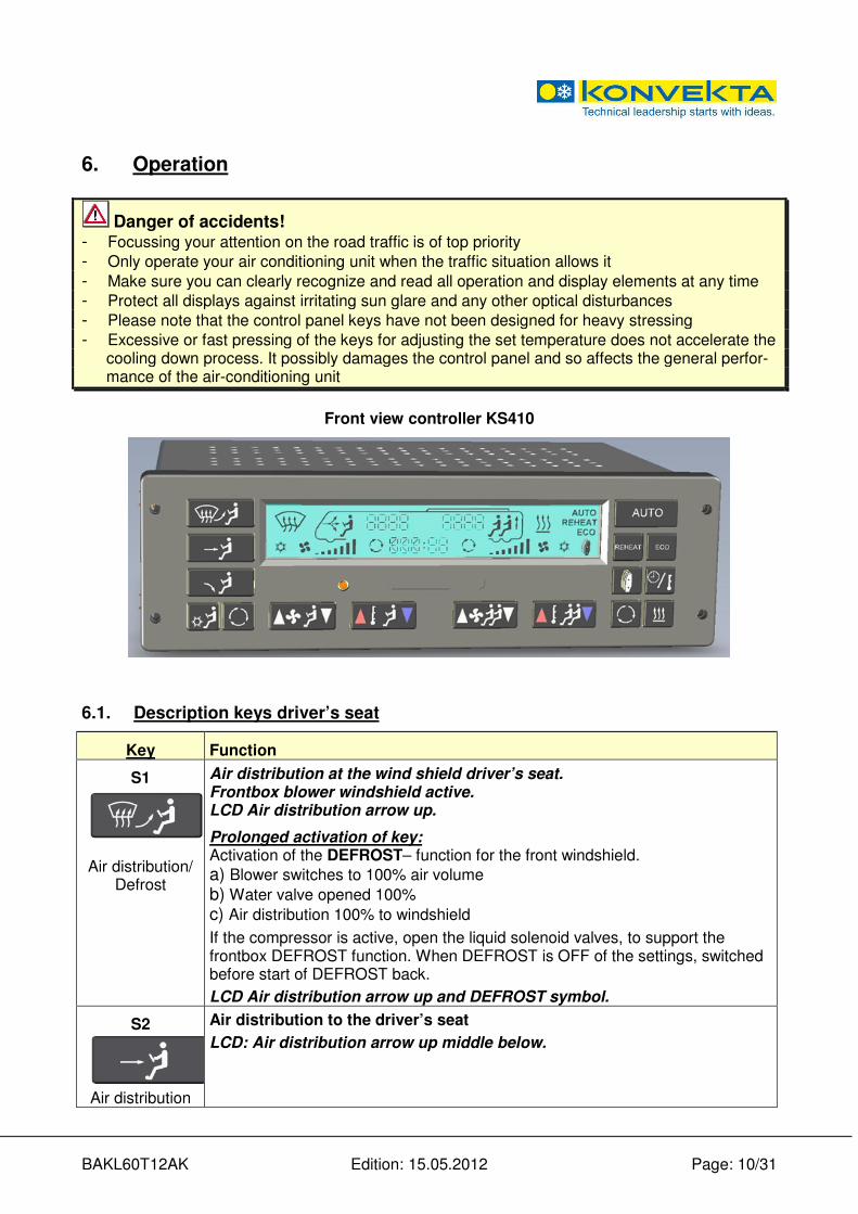
Front view controller KS410
6.1. Description keys driver’s seat
Key Function
S1
Air distribution/
Defrost
Air distribution at the wind shield driver’s seat. Frontbox blower windshield active. LCD Air distribution arrow up.
Prolonged activation of key: Activation of the DEFROST– function for the front windshield.
a) Blower switches to 100% air volume
b) Water valve opened 100%
c) Air distribution 100% to windshield
If the compressor is active, open the liquid solenoid valves, to support the frontbox DEFROST function. When DEFROST is OFF of the settings, switched before start of DEFROST back.
LCD Air distribution arrow up and DEFROST symbol.
S2
Air distribution
Air distribution to the driver’s seat
LCD: Air distribution arrow up middle below.

BAKL60T12AK Edition: 15.05.2012 Page: 11/31
Key Function
S3
Air distribution
Air distribution to the foot area driver’s seat LCD: Air distribution arrow down.
S4
Frontbox
Activate the frontbox
When AUTO is active, the frontbox can be activated. If it was OFF before, the front box blower is automatically adjusted to the minimum level.
S5
Recirculating air
flap
Operate the recirculating air flap at driver’s seat Recirculating air flap is permanently placed to recirculating air function. (Without automatic back space mechanism.)
S6
Blower
Adjust air volume driver’s seat
With Key S6 you can increase or decrease the set point. Setting of the frontbox blower is made in 7 stages. When ignition is ON without run of engine, the blower is limited to stage 3. While frontbox is activated, blower cannot be switched off. LCD: Bar graph left 1-7.
S7
Temperature adjustment
Adjustment of air temperature driver’s seat
With Key S7 you can increase or decrease the set point. The desired temperature can be set from 12 to 90°C in 10 levels. As a result of suitable positioning of the sensor in the frontbox, the outlet temperature to the driver is held constant.
LCD: Display left step 1-10.
7. Description keys passenger compartment
Key Function
S8
blower
Adjustment of air volume driver’s seat While AUTO operation, blower step is automatically adjusted depending on room temperature. With key S8, you can increase or reduce the air speed man-ually. The adjustment of the front box blower is implemented in 7 levels. When ignition is ON the blower is limited to 3 levels.
LCD: Bar graph right 1-7.
S9
Temperature
adjustment
Adjustment of room temperature in the passengers compartment With key S9, you can increase or reduce the set temperature. The set temperature can be adjusted from 12°C to 30°C. In AUTO mode, the temperature in the passenger space is fixed to the set tem-perature. LCD: Display right 12°C to 30°C.
BAKL60T12AK Edition: 15.05.2012 Page: 12/31
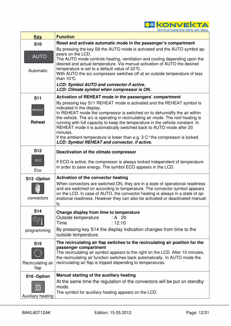
Key Function
S10
Automatic
Reset and activate automatic mode in the passenger’s compartment
By pressing the key S9 the AUTO mode is activated and the AUTO symbol ap-pears on the LCD. The AUTO mode controls heating, ventilation and cooling depending upon the desired and actual temperature. Via manual activation of AUTO the desired temperature is set to a default value of 22°C. With AUTO the a/c compressor switches off at an outside temperature of less than 10°C.
LCD: Symbol AUTO and convector if active. LCD: Climate symbol when compressor is ON.
S11
Reheat
Activation of REHEAT mode in the passengers’ compartment
By pressing key S11 REHEAT mode is activated and the REHEAT symbol is indicated in the display. In REHEAT mode the compressor is switched on to dehumidify the air within the vehicle. The a/c is operating in recirculating air mode. The roof heating is running with full capacity to keep the temperature in the vehicle constant. In REHEAT mode it is automatically switched back to AUTO mode after 20 minutes. If the ambient temperature is lower than e.g. 3 C° the compressor is locked. LCD: Symbol REHEAT and convector, if active.
S12
Eco
Deactivation of the climate compressor If ECO is active, the compressor is always locked independent of temperature
in order to save energy. The symbol ECO appears in the LCD.
S13 -Option
convectors
Activation of the convector heating
When convectors are switched ON, they are in a state of operational readiness and are switched on according to temperature. The convector symbol appears on the LCD. In case of AUTO, the convector heating is always in a state of op-erational readiness. However they can also be activated or deactivated manual-
ly.
S14
programming
Change display from time to temperature
Outside temperature : A 20 Time : 12:10
By pressing key S14 the display indication changes from time to the outside temperature.
S15
Recirculating air
flap
The recirculating air flap switches to the recirculating air position for the passenger compartment The recirculating air symbol appears to the right on the LCD. After 10 minutes,
the recirculating air function switches back automatically. In AUTO mode the recirculating air flap is tripped depending to temperatures.
S16 -Option
Auxiliary heating
Manual starting of the auxiliary heating
At the same time the regulation of the convectors will be put on standby mode. The symbol for auxiliary heating appears on the LCD.

BAKL60T12AK Edition: 15.05.2012 Page: 13/31
7.1. Time adjustment
Key Function
S1 +
S14
S9
The time can be programmed only when the ignition is off.
By simultaneous pressing of S1 and S14 at display day flashes up. (z. B. „DAY1“) With key S14, the adjustment is changed between day and time. With key S9, the selected value can be changed and increased or reduced.
DAY 1 = Monday DAY 2 = Tuesday DAY 3 = Wednesday DAY 4 = Thursday DAY 5 = Friday DAY 6 = Saturday DAY 7 = Sunday After programming the time, the display switches back automatically after 5 sec. to (or by simultaneous pressing of S1 and S14) the normal display.
7.2. Adjust starting time of the additional heating
Key Function
S1 +
S16
S9
Starting time of the additional heating programmed With ignition „OFF” the starting time of the auxiliary heating can be programmed. Via pressing simultaneously keys S1 and S16 the day is blinking. (e.g.: „dAY0“ ) With key S16, the adjustment is changed between day, time and ON/OFF. With key S9 the selected value can be changed, increased or reduced
Programming without day:
If start of the auxiliary heating system should not depend on the weekday, the adjustment must be on "dAY0” (every day). In the pre-selection you have to enter the starting time with S9 and with „ON / OFF“ you have to choose, whether the additional heating system should start at the adjusted time.
Programming with day:
If the auxiliary heating system should start on defined days, for every day Mon. - Sun. = ”dAY1" - "day7" a separate schedule can be adjusted. For this pur-pose, you select the required day with S9, after that select the time, and with "ON/OFF" select whether the auxiliary heating should start on the adjusted day and time. After the programming of the auxiliary heating / time, the display switches back automatically after 5 s. (or through pressing key S1 and S16) to the normal display. If a pre-selection is activated, with ignition OFF, the next starting time appears on the display in addition to the time.
dAY0 0600 PrEH
BAKL60T12AK Edition: 15.05.2012 Page: 14/31
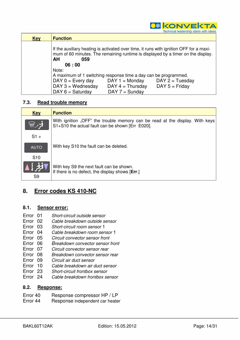
Key Function If the auxiliary heating is activated over time, it runs with ignition OFF for a maxi-mum of 60 minutes. The remaining runtime is displayed by a timer on the display.
AH 059 06 : 00 Note: A maximum of 1 switching response time a day can be programmed.
DAY 0 = Every day DAY 1 = Monday DAY 2 = Tuesday DAY 3 = Wednesday DAY 4 = Thursday DAY 5 = Friday DAY 6 = Saturday DAY 7 = Sunday
7.3. Read trouble memory
Key Function
S1 +
S10
S9
With ignition „OFF” the trouble memory can be read at the display. With keys S1+S10 the actual fault can be shown [Err E020]. With key S10 the fault can be deleted. With key S9 the next fault can be shown. If there is no defect, the display shows [Err.]
8. Error codes KS 410-NC
8.1. Sensor error:
Error 01 Short-circuit outside sensor
Error 02 Cable breakdown outside sensor
Error 03 Short-circuit room sensor 1
Error 04 Cable breakdown room sensor 1
Error 05 Circuit convector sensor front
Error 06 Breakdown convector sensor front
Error 07 Circuit convector sensor rear
Error 08 Breakdown convector sensor rear Error 09 Circuit air duct sensor
Error 10 Cable breakdown air duct sensor Error 23 Short-circuit frontbox sensor Error 24 Cable breakdown frontbox sensor
8.2. Response:
Error 40 Response compressor HP / LP Error 44 Response independent car heater

BAKL60T12AK Edition: 15.05.2012 Page: 15/31
8.3. Potentiometer response:
Error 63 error roof valve potentiometer Error 64 error convector valve potentiometer Error 65 error frontbox valve potentiometer Error 68 error frontbox air distribution flap potentiometer
8.4. Digital outputs (DA):
Error 100 Short circuit DA evaporator blower level 1 (release DZM ) Error 101 Short circuit DA evaporator blower level 2 Error 102 Short circuit DA evaporator blower level 3 Error 103 Short circuit DA compressor Error 105 Short circuit DA condenser Error 107 Short circuit DA auxiliary heating Error 108 Short circuit DA water pump Error 109 Short circuit DA air conditioning circulating air damper 1/A Error 110 Short circuit DA air conditioning circulating air damper 1/B Error 113 Short circuit DA roof water valve A Error 114 Short circuit DA roof water valve B Error 117 Short circuit DA convector water valve A Error 118 Short circuit DA convector water valve B Error 121 Short circuit DA frontbox water valve A Error 122 Short circuit DA frontbox water valve B Error 123 Short circuit DA frontbox circulating air damper A Error 124 Short circuit DA frontbox circulating air damper B Error 125 Short circuit DA frontbox air flap A Error 126 Short circuit DA frontbox air flap B Error 134 Short circuit DA frontbox air conditioning Error 145 Short circuit DA lower chair blower of 1 level 1 Error 146 Short circuit DA lower chair blower of 1 level 2
8.5. Webasto error message auxiliary heating device:
Error Number Error coding = no start in the safety time 188 Error coding = flame interruption from burning operation, repeat start unsuccessful 189 Error coding = low-voltage identification 190 Error coding = extraneous light identification in the preliminary/over-running 191 Error coding = flame monitor defective 192 Error coding = temperature detector = defective 193 Error coding = solenoid valve defective 194 Error coding = combustion-air blower fan motor defective 195 Error coding = circulation pump defective 196 Error coding = temperature limiter (thermostat) defective 197 Error coding = ignition radio transmitter defective 198 Error coding = heater interlocking through error/flame interruption 199 Legend: DA : digital output AE : analog input (Sensor) DE : digital input VPOT : analog input (control motor) AA : analog output ZBR : central board computer
BAKL60T12AK Edition: 15.05.2012 Page: 16/31
9. Maintenance / Service
Please arrange regular dates for maintenance works and services with a KONVEKTA service sta-tion, as indicated in maintenance schedule bus no. WP07050618. On our website www.konvekta.com in category >service< you will find a survey of contact details of all our service partners close to your location.
- Only qualified staff is allowed to carry out these works! -
For general instructions on repair – and maintenance works please contact via email: [email protected]
Danger of accidents! Qualified staff in charge of installation and maintenance have to be trained in accordance with EN 378-Part 4 and (EG) No.307 / 2008 and must strictly follow the legal provisions. Any works or modifications at the air conditioner which are carried out improperly can lead to mal-function and so endanger operational reliability. We recommend having all works and modifications carried out at an authorized KONVEKTA Service Station. Before carrying out any maintenance works at your air conditioning unit, carefully read the KONVKETA safety provisions (TD00052A� ) in order to avoid any dangers and accidents!
� Source of supply: KONVEKTA AG, P.O. Box 2280, D-34607 Schwalmstadt
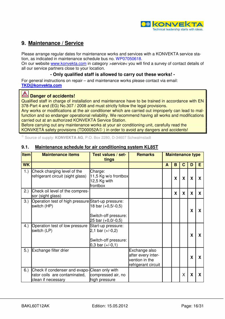
9.1. Maintenance schedule for air conditioning system KL85T
Item Maintenance items Test values / set-tings
Remarks Maintenance type
WK A B C D E
1.) Check charging level of the refrigerant circuit (sight glass)
Charge: 11,5 Kg w/o frontbox 12,5 Kg with frontbox
X X X X
2.) Check oil level of the compres-sor (sight glass)
X X X X
3.) Operation test of high pressure switch (HP)
Start-up pressure: 18 bar (+0,5/-0,5) Switch-off pressure: 25 bar (+0,0/-0,5)
X X
4.) Operation test of low pressure switch (LP)
Start-up pressure: 2,1 bar (+/-0,2) Switch-off pressure: 0,3 bar (+/-0,1)
X X
5.) Exchange filter drier Exchange also after every inter-vention in the refrigerant circuit
X X
6.) Check if condenser and evapo-rator coils are contaminated, clean if necessary
Clean only with compressed air, no high pressure
X X X
BAKL60T12AK Edition: 15.05.2012 Page: 17/31
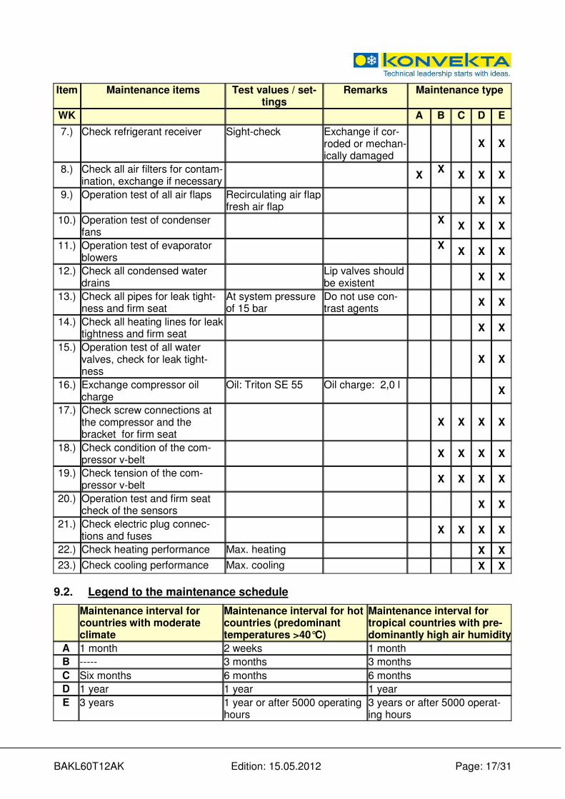
Item Maintenance items Test values / set-tings
Remarks Maintenance type
WK A B C D E
7.) Check refrigerant receiver Sight-check Exchange if cor-roded or mechan-ically damaged
X X
8.) Check all air filters for contam-ination, exchange if necessary
X
X X X X
9.) Operation test of all air flaps Recirculating air flap fresh air flap
X X
10.) Operation test of condenser fans
X X X X
11.) Operation test of evaporator blowers
X X X X
12.) Check all condensed water drains
Lip valves should be existent
X X
13.) Check all pipes for leak tight-ness and firm seat
At system pressure of 15 bar
Do not use con-trast agents
X X
14.) Check all heating lines for leak tightness and firm seat
X X
15.) Operation test of all water valves, check for leak tight-ness
X X
16.) Exchange compressor oil charge
Oil: Triton SE 55 Oil charge: 2,0 l
X
17.) Check screw connections at the compressor and the bracket for firm seat
X X X X
18.) Check condition of the com-pressor v-belt
X X X X
19.) Check tension of the com-pressor v-belt
X X X X
20.) Operation test and firm seat check of the sensors
X X
21.) Check electric plug connec-tions and fuses
X X X X
22.) Check heating performance Max. heating X X
23.) Check cooling performance Max. cooling X X
9.2. Legend to the maintenance schedule
Maintenance interval for countries with moderate climate
Maintenance interval for hot countries (predominant temperatures >40°C)
Maintenance interval for tropical countries with pre-dominantly high air humidity
A 1 month 2 weeks 1 month
B ----- 3 months 3 months
C Six months 6 months 6 months
D 1 year 1 year 1 year
E 3 years 1 year or after 5000 operating hours
3 years or after 5000 operat-ing hours
BAKL60T12AK Edition: 15.05.2012 Page: 18/31
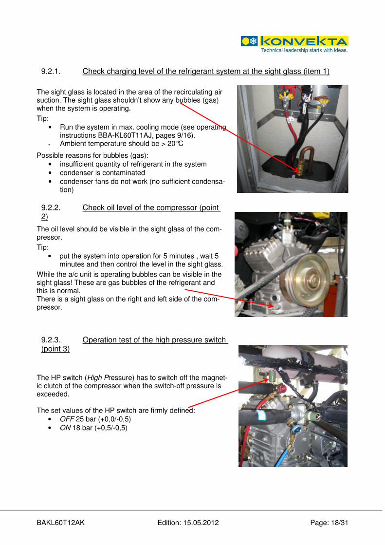
9.2.1. Check charging level of the refrigerant system at the sight glass (item 1)
The sight glass is located in the area of the recirculating air suction. The sight glass shouldn’t show any bubbles (gas) when the system is operating.
Tip:
• Run the system in max. cooling mode (see operating instructions BBA-KL60T11AJ, pages 9/16).
• Ambient temperature should be > 20°C
Possible reasons for bubbles (gas):
• insufficient quantity of refrigerant in the system
• condenser is contaminated
• condenser fans do not work (no sufficient condensa-tion)
9.2.2. Check oil level of the compressor (point 2)
The oil level should be visible in the sight glass of the com-pressor.
Tip:
• put the system into operation for 5 minutes , wait 5 minutes and then control the level in the sight glass.
While the a/c unit is operating bubbles can be visible in the sight glass! These are gas bubbles of the refrigerant and this is normal. There is a sight glass on the right and left side of the com-pressor.
9.2.3. Operation test of the high pressure switch (point 3)
The HP switch (High Pressure) has to switch off the magnet-ic clutch of the compressor when the switch-off pressure is exceeded. The set values of the HP switch are firmly defined:
• OFF 25 bar (+0,0/-0,5)
• ON 18 bar (+0,5/-0,5)

BAKL60T12AK Edition: 15.05.2012 Page: 19/31
Bring the a/c unit to HP fault. For that purpose remove the fuses (15A) of the condenser fans (F7-F11) which are located on the electric switch plate behind the recirculating air grid. Tip:
• Operate the unit in max. cooling mode (see Operating Instruction BBA-KL60T11AJ, page 9/16)
If the magnetic clutch is not switched off after the pressure has exceeded 25 bar, the HP switch is defective and has to be replaced!
9.2.4. Operation test of low pressure switch (point 4)
The LP switch (Low Pressure) has to switch off the magnetic clutch when the switch-off pressure falls below the set value. The set values of the HP switch are firmly defined:
• OFF 0,3 bar (+/-0,1)
• ON 2,1 bar (+/-0,2) Bring the a/c unit to LP fault. For that purpose remove the fuse (7,5 A) of the magnetic valve (F13) which is located on the electric switch plate behind the recirculating air grid. Tip:
• operate the unit in max. cooling mode (see Operating Instruction BBA-KL60T11AJ, page 9/16)
If the magnetic clutch is not switched off at a pressure of 0,3 bar, the LP switch is defective and has to be replaced!
BAKL60T12AK Edition: 15.05.2012 Page: 20/31
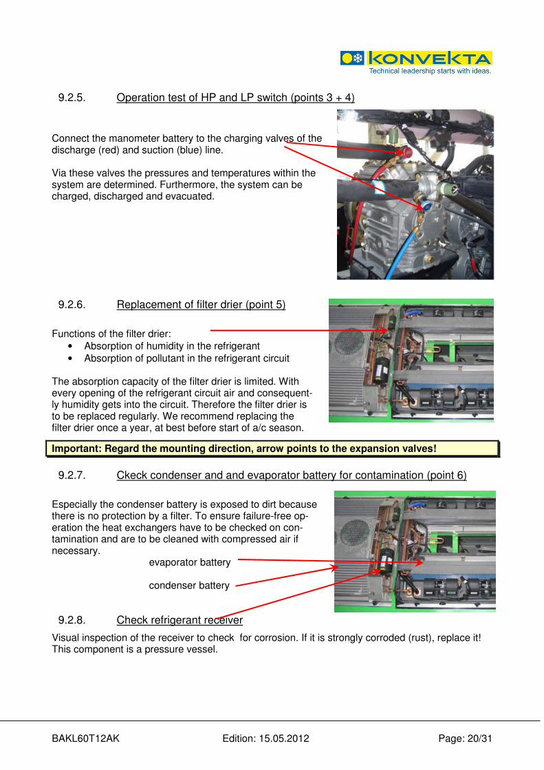
9.2.5. Operation test of HP and LP switch (points 3 + 4)
Connect the manometer battery to the charging valves of the discharge (red) and suction (blue) line. Via these valves the pressures and temperatures within the system are determined. Furthermore, the system can be charged, discharged and evacuated.
9.2.6. Replacement of filter drier (point 5)
Functions of the filter drier:
• Absorption of humidity in the refrigerant
• Absorption of pollutant in the refrigerant circuit
The absorption capacity of the filter drier is limited. With every opening of the refrigerant circuit air and consequent-ly humidity gets into the circuit. Therefore the filter drier is to be replaced regularly. We recommend replacing the filter drier once a year, at best before start of a/c season.
Important: Regard the mounting direction, arrow points to the expansion valves!
9.2.7. Ckeck condenser and and evaporator battery for contamination (point 6)
Especially the condenser battery is exposed to dirt because there is no protection by a filter. To ensure failure-free op-eration the heat exchangers have to be checked on con-tamination and are to be cleaned with compressed air if necessary.
evaporator battery
condenser battery
9.2.8. Check refrigerant receiver
Visual inspection of the receiver to check for corrosion. If it is strongly corroded (rust), replace it! This component is a pressure vessel.
BAKL60T12AK Edition: 15.05.2012 Page: 21/31
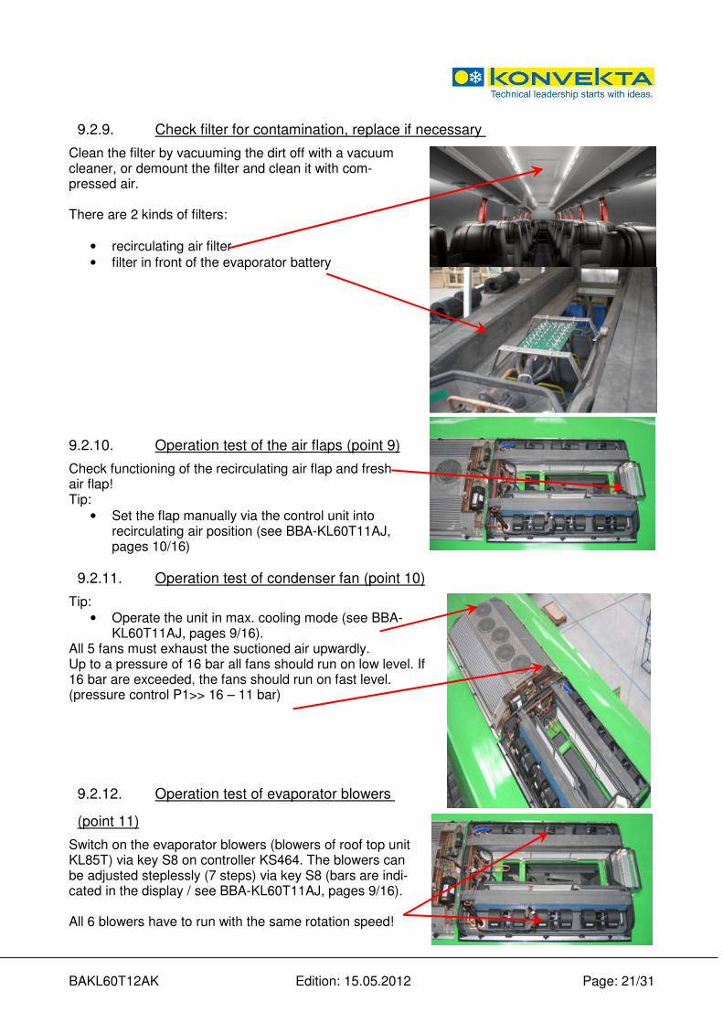
9.2.9. Check filter for contamination, replace if necessary
Clean the filter by vacuuming the dirt off with a vacuum cleaner, or demount the filter and clean it with com-pressed air. There are 2 kinds of filters:
• recirculating air filter
• filter in front of the evaporator battery
9.2.10. Operation test of the air flaps (point 9)
Check functioning of the recirculating air flap and fresh air flap! Tip:
• Set the flap manually via the control unit into recirculating air position (see BBA-KL60T11AJ, pages 10/16)
9.2.11. Operation test of condenser fan (point 10)
Tip:
• Operate the unit in max. cooling mode (see BBA-KL60T11AJ, pages 9/16).
All 5 fans must exhaust the suctioned air upwardly. Up to a pressure of 16 bar all fans should run on low level. If 16 bar are exceeded, the fans should run on fast level. (pressure control P1>> 16 – 11 bar)
9.2.12. Operation test of evaporator blowers
(point 11)
Switch on the evaporator blowers (blowers of roof top unit KL85T) via key S8 on controller KS464. The blowers can be adjusted steplessly (7 steps) via key S8 (bars are indi-cated in the display / see BBA-KL60T11AJ, pages 9/16). All 6 blowers have to run with the same rotation speed!
BAKL60T12AK Edition: 15.05.2012 Page: 22/31
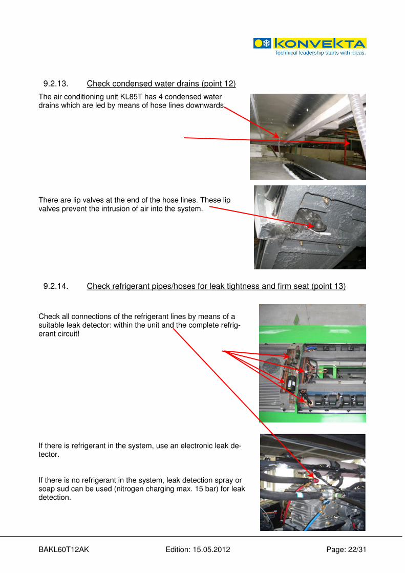
9.2.13. Check condensed water drains (point 12)
The air conditioning unit KL85T has 4 condensed water drains which are led by means of hose lines downwards. There are lip valves at the end of the hose lines. These lip valves prevent the intrusion of air into the system.
9.2.14. Check refrigerant pipes/hoses for leak tightness and firm seat (point 13)
Check all connections of the refrigerant lines by means of a suitable leak detector: within the unit and the complete refrig-erant circuit! If there is refrigerant in the system, use an electronic leak de-tector. If there is no refrigerant in the system, leak detection spray or soap sud can be used (nitrogen charging max. 15 bar) for leak detection.
BAKL60T12AK Edition: 15.05.2012 Page: 23/31
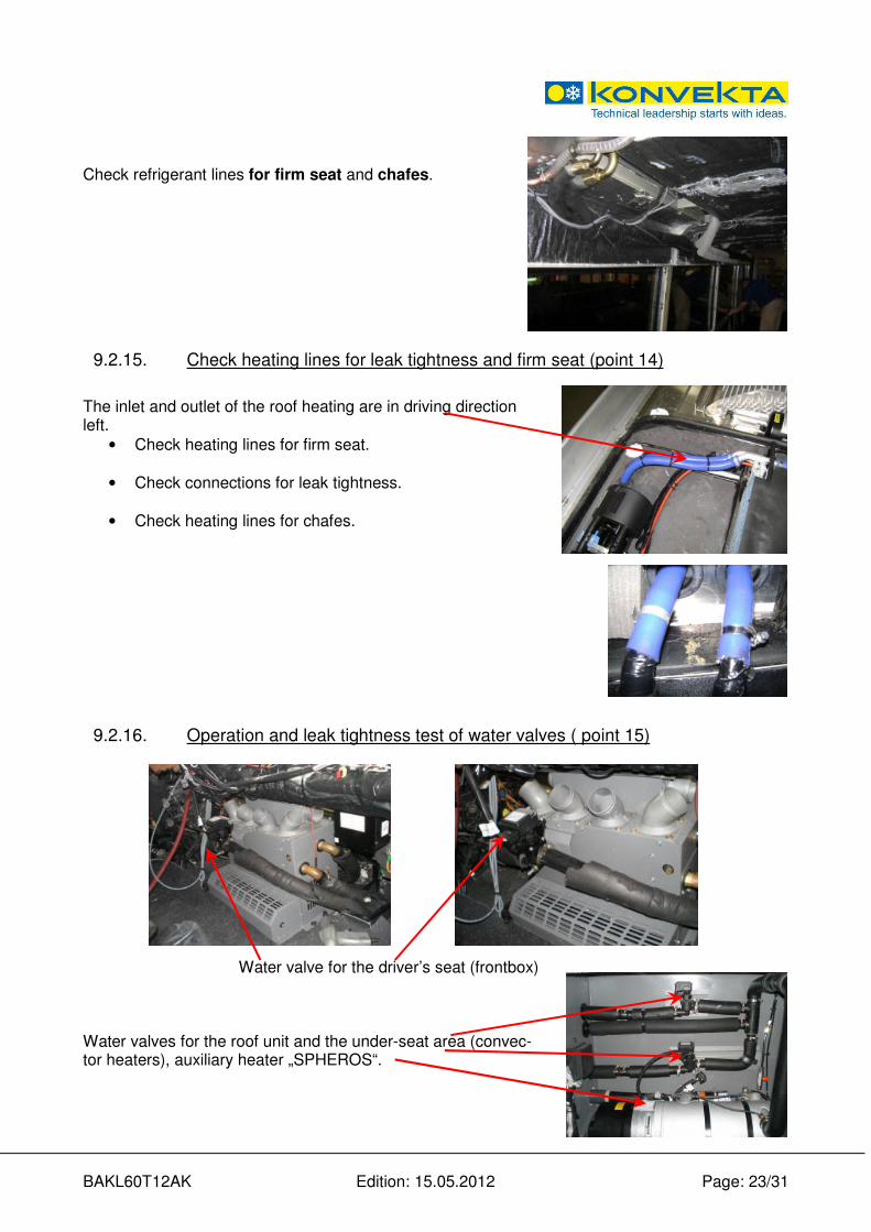
Check refrigerant lines for firm seat and chafes.
9.2.15. Check heating lines for leak tightness and firm seat (point 14)
The inlet and outlet of the roof heating are in driving direction left.
• Check heating lines for firm seat.
• Check connections for leak tightness.
• Check heating lines for chafes.
9.2.16. Operation and leak tightness test of water valves ( point 15)
Water valve for the driver’s seat (frontbox) Water valves for the roof unit and the under-seat area (convec-tor heaters), auxiliary heater „SPHEROS“.
BAKL60T12AK Edition: 15.05.2012 Page: 24/31
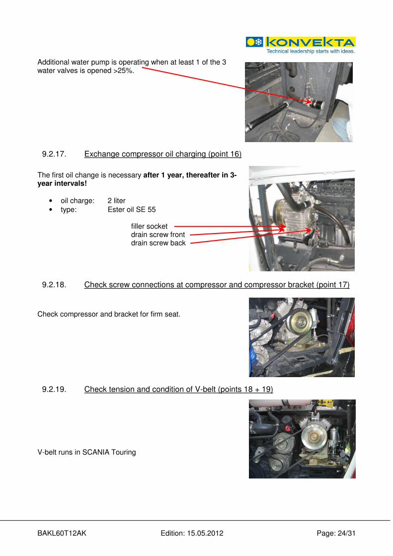
Additional water pump is operating when at least 1 of the 3 water valves is opened >25%.
9.2.17. Exchange compressor oil charging (point 16)
The first oil change is necessary after 1 year, thereafter in 3-year intervals!
• oil charge: 2 liter
• type: Ester oil SE 55
filler socket drain screw front drain screw back
9.2.18. Check screw connections at compressor and compressor bracket (point 17)
Check compressor and bracket for firm seat.
9.2.19. Check tension and condition of V-belt (points 18 + 19)
V-belt runs in SCANIA Touring
BAKL60T12AK Edition: 15.05.2012 Page: 25/31
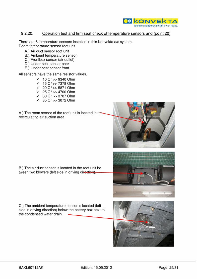
9.2.20. Operation test and firm seat check of temperature sensors and (point 20)
There are 6 temperature sensors installed in this Konvekta a/c system. Room temperature sensor roof unit
A.) Air duct sensor roof unit B.) Ambient temperature sensor C.) Frontbox sensor (air outlet) D.) Under-seat sensor back E.) Under-seat sensor front
All sensors have the same resistor values.
� 10 C° >> 9340 Ohm � 15 C° >> 7378 Ohm � 20 C° >> 5871 Ohm � 25 C° >> 4700 Ohm � 30 C° >> 3787 Ohm � 35 C° >> 3072 Ohm
A.) The room sensor of the roof unit is located in the recirculating air suction area
B.) The air duct sensor is located in the roof unit be-tween two blowers (left side in driving direction). C.) The ambient temperature sensor is located (left side in driving direction) below the battery box next to the condensed water drain.
BAKL60T12AK Edition: 15.05.2012 Page: 26/31
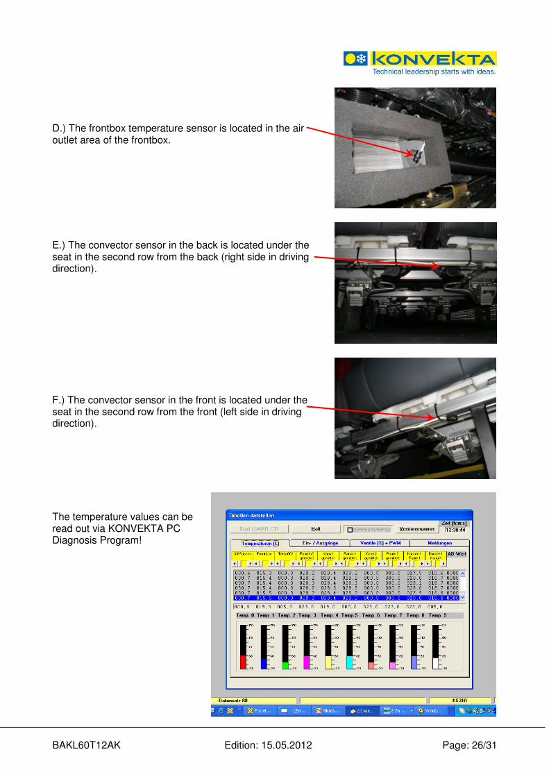
D.) The frontbox temperature sensor is located in the air outlet area of the frontbox. E.) The convector sensor in the back is located under the seat in the second row from the back (right side in driving direction).
F.) The convector sensor in the front is located under the seat in the second row from the front (left side in driving direction). The temperature values can be read out via KONVEKTA PC Diagnosis Program!

BAKL60T12AK Edition: 15.05.2012 Page: 27/31
9.2.21. Check plug connections and fuses (point 21)
Check plugs connections for firm seat: Plug connections at controller KS410 Plug connections at KL85T Plug connections in the engine compartment:
� at the compressor
� at the water valves
� at the water pump

BAKL60T12AK Edition: 15.05.2012 Page: 28/31
Check all fuse sizes according to wiring diagram BK1-70T-143. Fuses of the roof unit components Main fuse 125 A in the engine compartment
9.2.22. Check heating perfomance (point 22)
Tip:
• Operate the unit in max. heating mode (see BBA-KL60T11AJ, pages 9/16)
• Operate all evapora-tor blowers 100%
• Frontbox blower runs 100%
• All heating valves are 100% opened
• Check temperature development of the sensors via KON-VEKTA PC Diagno-sis Program

BAKL60T12AK Edition: 15.05.2012 Page: 29/31
9.2.23. Check cooling perfomance (point 23)
Tip:
• Operate the unit in max. cooling mode (see BBA-KL60T11AJ, pages 9/16)
• Operate all evaporator blowers 100%
• Frontbox blower runs 100%
• Condenser fans are switched on
• Magnetic clutch of the compressor is switched on
• All heating valves are closed
• Check temperature development of the sensors via KON-VEKTA PC Diagnosis Program
9.2.24. Fresh air / recirculating air filter
The fresh air / recirculating air filter is to be cleaned monthly or if it is contaminated heavily, weekly (clean with compresses air). The fresh air / recirculating air filter is located in the roof unit in front of the evaporator battery. It can be removed through the recirculating air suction (inside the vehicle) and by opening the unit cover (outside). If the filter is defective, it has to be replaced immediately.
9.2.25. Condenser battery
Please pay attention to the condenser fins, they have to be clean. When the fins are contaminated heavily, the system will automatically indicate failure due to high pressure.
Note:
The condenser fins are to be cleaned at least twice a year (with compressed air), or more often if the fins are contaminated heavily.
BAKL60T12AK Edition: 15.05.2012 Page: 30/31
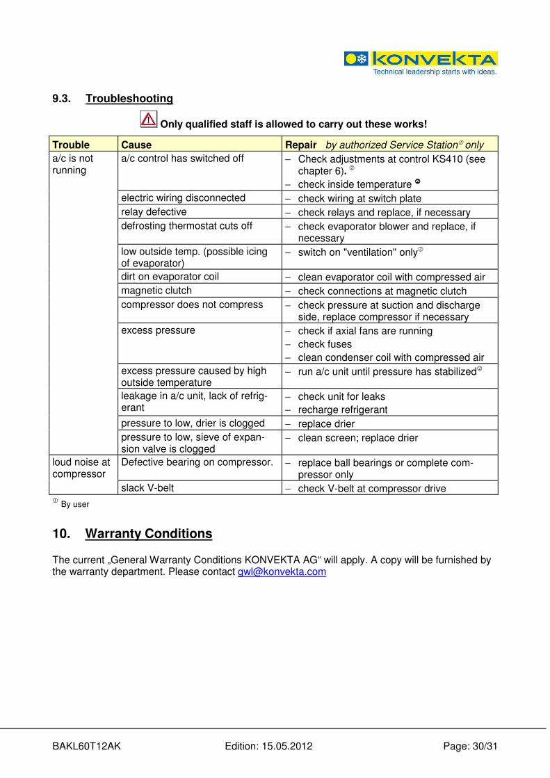
9.3. Troubleshooting
Only qualified staff is allowed to carry out these works!
Trouble Cause Repair by authorized Service Station� only
a/c is not running
a/c control has switched off − Check adjustments at control KS410 (see chapter 6).
2
− check inside temperature 2222
electric wiring disconnected − check wiring at switch plate
relay defective − check relays and replace, if necessary
defrosting thermostat cuts off − check evaporator blower and replace, if necessary
low outside temp. (possible icing of evaporator)
− switch on "ventilation" only2
dirt on evaporator coil − clean evaporator coil with compressed air
magnetic clutch − check connections at magnetic clutch
compressor does not compress − check pressure at suction and discharge side, replace compressor if necessary
excess pressure − check if axial fans are running
− check fuses
− clean condenser coil with compressed air
excess pressure caused by high outside temperature
− run a/c unit until pressure has stabilized2
leakage in a/c unit, lack of refrig-erant
− check unit for leaks
− recharge refrigerant
pressure to low, drier is clogged − replace drier
pressure to low, sieve of expan-sion valve is clogged
− clean screen; replace drier
loud noise at compressor
Defective bearing on compressor. − replace ball bearings or complete com-pressor only
slack V-belt − check V-belt at compressor drive 1 By user
10. Warranty Conditions
The current „General Warranty Conditions KONVEKTA AG“ will apply. A copy will be furnished by the warranty department. Please contact [email protected]

BAKL60T12AK Edition: 15.05.2012 Page: 31/31
11. Waste disposal in accordance with legal provisions
After the phase of use the last proprietor is responsible for the adequate waste manage-ment. The environmental regulations in the exporting country must be observed. The following list contains the most important regulating literature, valid for the Federal Rep. of Germany:
• Resolution for dangerous substances
• Law for waste circulation (KRW/AfgG))
• Resolution for the proofs of utilization and removal
• Criminal Code (StGB) 28th section „cri-minal acts against the environment” §326 - Environment jeopardizing waste management
• Law of chemicals § 27 - penal prescrip-tions
• Resolution for used oil
• Law of water balance
• Resolution for the waste management of old cars and the adaptation of road prescriptions
• Resolution (EC) No. 2037/2000 of the Euro-pean Parliament and of the Council for mate-rials that affect the ozone layer
• Resolution to prohibit certain ozone destroying halogen hydrocarbons.
The used refrigerant endangers the environment. When dealing with refrigerants the existing pre-scriptions and regulations are to be followed. Only qualified staff is allowed to carry out these works!
Water endangering substances - acc. to §§19g-19l - are solid, liquid, and gaseous substances. e.g.: mineral and tar oils (cooling oils), halogen containing organic combinations (refrigerants).
Source of supply: - Bundesanzeiger - Beuth Verlag - dtv (Deutscher Taschenbuch Verlag
12. History of modification
Version Date Name Remark File
A00 15.03.2011 B. Keßler Source file BAKL60T12AK
A01 15.05.2012 B. Keßler Refrigerant charge was 11.5kg; cover title was Scania Higer A80
BAKL60T12AK
A02 16.03.2017 B. Keßler Information on the operating instructions and technical data expanded with F-gas-regulation; Point 11 updaed
BAKL60T12AK