Embed Size (px)
Citation preview
KNEE
HIP
SHOULDER
EXTREMITIES
*smith&nephew
KNEE TECHNIQUE GUIDE
ACUFEX™ PINPOINT Anatomic ACL Guide SystemDarren L. Johnson, MD Luigi A. Pederzini, MD
10600951C_ACUFEX _PINPOINT.indd 1 4/18/12 9:54 AM

10600951C_ACUFEX _PINPOINT.indd 2 4/18/12 9:54 AM
3KNEE TECHNIQUE GUIDE 10600951 Rev. C
ACUFEX™ PINPOINT Anatomic ACL Guide System
The Smith & Nephew ACUFEX PINPOINT Anatomic ACL Guide System addresses some of the challenges associated with performing anatomic ACL reconstruction. Although there are often soft tissue remnants or bony landmarks that can help surgeons locate the femoral insertion site, sometimes these anatomic markers are not clear making it more challenging to drill femoral tunnels within the native ACL footprint. To add to the difficulty, there is tremendous size variability of the native insertion sites on the femur and tibia.
The ACUFEX PINPOINT Anatomic ACL Guide System helps ensure anatomic placement and acts as a template to allow the surgeon to visualize the tunnels before committing to a location or size. To address the variability in size of the native ACL, the guide helps the surgeon determine whether a single bundle or double bundle ACL technique is possible. Patients with a tibial insertion site size of greater than 16 mm are often candidates for double bundle surgery to ensure that the majority of the native ACL footprint is reproduced with the surgery.
The ACUFEX PINPOINT Anatomic ACL Guide System is easy to use and can be modified to address different technique preferences for drilling, including inside-out and outside-in, based on surgeon preference. Additionally, the guide system allows the surgeon to perform anatomic ACL surgery in a skeletally immature child by drilling the femoral tunnel as an all-epiphyseal outside-in technique.
This guide system offers the following advantages:
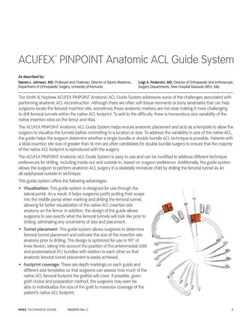
• Visualization: This guide system is designed for use through the lateral portal. As a result, it helps surgeons justify putting their scope into the middle portal when marking and drilling the femoral tunnel, allowing for better visualization of the native ACL insertion site anatomy on the femur. In addition, the design of the guide allows surgeons to see exactly what the femoral tunnels will look like prior to drilling, eliminating any uncertainty of size and placement.
• Tunnel placement: This guide system allows surgeons to determine femoral tunnel placement and estimate the size of the insertion site anatomy prior to drilling. The design is optimized for use in 90° of knee flexion, taking into account the position of the anteromedial (AM) and posterolateral (PL) bundles with relation to each other so that anatomic femoral tunnel placement is easily achieved.
• Footprint coverage: There are depth markings on each guide and different size templates so that surgeons can assess how much of the native ACL femoral footprint the graft(s) will cover. If possible, given graft choice and preparation method, the surgeons may even be able to individualize the size of the graft to maximize coverage of the patient’s native ACL footprint.
As described by:Darren L. Johnson, MD, Professor and Chairman, Director of Sports Medicine, Department of Orthopaedic Surgery, University of Kentucky
Luigi A. Pederzini, MD, Director of Orthopaedic and Arthroscopic Surgery Departments, New Hospital Sassuolo (MO), Italy
10600951C_ACUFEX _PINPOINT.indd 3 4/18/12 9:54 AM
4 KNEE TECHNIQUE GUIDE 10600951 Rev. C
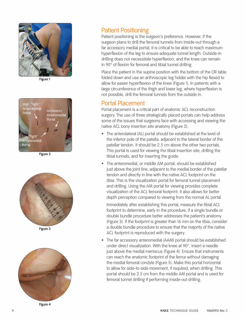
Patient PositioningPatient positioning is the surgeon's preference. However, if the surgeon plans to drill the femoral tunnels from inside-out through a far accessory medial portal, it is critical to be able to reach maximum hyperflexion of the leg to ensure adequate tunnel length. Outside-in drilling does not necessitate hyperflexion, and the knee can remain in 90° of flexion for femoral and tibial tunnel drilling.
Place the patient in the supine position with the bottom of the OR table folded down and use an arthroscopic leg holder with the hip flexed to allow for easier hyperflexion of the knee (Figure 1). In patients with a large circumference of the thigh and lower leg, where hyperflexion is not possible, drill the femoral tunnels from the outside in.
Portal PlacementPortal placement is a critical part of anatomic ACL reconstruction surgery. The use of three strategically placed portals can help address some of the issues that surgeons face with accessing and viewing the native ACL bony insertion site anatomy (Figure 2).
• The anterolateral (AL) portal should be established at the level of the inferior pole of the patella, adjacent to the lateral border of the patellar tendon. It should be 2.5 cm above the other two portals. This portal is used for viewing the tibial insertion site, drilling the tibial tunnels, and for inserting the guide.
• The anteromedial, or middle AM portal, should be established just above the joint line, adjacent to the medial border of the patellar tendon and directly in line with the native ACL footprint on the tibia. This is the visualization portal for femoral tunnel placement and drilling. Using the AM portal for viewing provides complete visualization of the ACL femoral footprint. It also allows for better depth perception compared to viewing from the normal AL portal.
Immediately after establishing this portal, measure the tibial ACL footprint to determine, early in the procedure, if a single bundle or double bundle procedure better addresses the patient’s anatomy (Figure 3). If the footprint is greater than 16 mm on the tibia, consider a double bundle procedure to ensure that the majority of the native ACL footprint is reproduced with the surgery.
• The far accessory anteromedial (AAM) portal should be established under direct visualization. With the knee at 90°, insert a needle just above the medial meniscus (Figure 4). Ensure that instruments can reach the anatomic footprint of the femur without damaging the medial femoral condyle (Figure 5). Make this portal horizontal to allow for side-to-side movement, if required, when drilling. This portal should be 2.5 cm from the middle AM portal and is used for femoral tunnel drilling if performing inside-out drilling.
Figure 1
Accessory Anteromedial Portal
Low “Tight” Anteromedial Portal
High “Tight” Anterolateral Portal
Figure 2
Figure 3
Figure 4
10600951C_ACUFEX _PINPOINT.indd 4 4/18/12 9:54 AM
5KNEE TECHNIQUE GUIDE 10600951 Rev. C
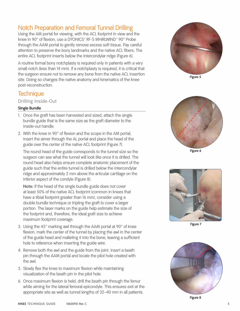
Notch Preparation and Femoral Tunnel DrillingUsing the AM portal for viewing, with the ACL footprint in view and the knee in 90° of flexion, use a DYONICS™ RF-S WHIRLWIND™ 90° Probe through the AAM portal to gently remove excess soft tissue. Pay careful attention to preserve the bony landmarks and the native ACL fibers. The entire ACL footprint inserts below the intercondylar ridge (Figure 6).
A routine formal bony notchplasty is required only in patients with a very small notch (less than 14 mm). If a notchplasty is required, it is critical that the surgeon ensure not to remove any bone from the native ACL insertion site. Doing so changes the native anatomy and kinematics of the knee post-reconstruction.
TechniqueDrilling Inside-OutSingle Bundle
1. Once the graft has been harvested and sized, attach the single bundle guide that is the same size as the graft diameter to the inside-out handle.
2. With the knee in 90° of flexion and the scope in the AM portal, insert the aimer through the AL portal and place the head of the guide over the center of the native ACL footprint (Figure 7).
The round head of the guide corresponds to the tunnel size so the surgeon can see what the tunnel will look like once it is drilled. The round head also helps ensure complete anatomic placement of the guide such that the entire tunnel is drilled below the intercondylar ridge and approximately 2 mm above the articular cartilage on the inferior aspect of the condyle (Figure 8).
Note: If the head of the single bundle guide does not cover at least 50% of the native ACL footprint (common in knees that have a tibial footprint greater than 16 mm), consider using a double bundle technique or tripling the graft to cover a larger portion. The laser marks on the guide help estimate the size of the footprint and, therefore, the ideal graft size to achieve maximum footprint coverage.
3. Using the 45° marking awl through the AAM portal at 90° of knee flexion, mark the center of the tunnel by placing the awl in the center of the guide head and malleting it into the bone, leaving a sufficient hole to reference when inserting the guide wire.
4. Remove both the awl and the guide from the joint. Insert a beath pin through the AAM portal and locate the pilot hole created with the awl.
5. Slowly flex the knee to maximum flexion while maintaining visualization of the beath pin in the pilot hole.
6. Once maximum flexion is held, drill the beath pin through the femur while aiming for the lateral femoral epicondyle. This ensures exit at the appropriate site as well as tunnel lengths of 32–40 mm in all patients.
Figure 5
Figure 6
Figure 7
Figure 8
10600951C_ACUFEX _PINPOINT.indd 5 4/18/12 9:54 AM
6 KNEE TECHNIQUE GUIDE 10600951 Rev. C
7. Maintain the knee in the flexed position for the remainder of femoral tunnel preparation.
8. Using the 4.5 mm ENDOBUTTON™ Drill Bit over the beath pin, drill the femoral tunnel, ensuring to breach the cortex.
9. Remove the drill and the pin and measure the total length of the femoral tunnel (32–40 mm) using the ENDOBUTTON Depth Probe.
10. Once the tunnel length is determined, reinsert the pin through the tunnel and drill a socket with a single fluted acorn drill bit that corresponds to the diameter of the graft. Be sure to drill the socket 10 mm deeper than the desired graft depth to ensure ample distance to flip the ENDOBUTTON CL ULTRA Fixation Device.
Double Bundle
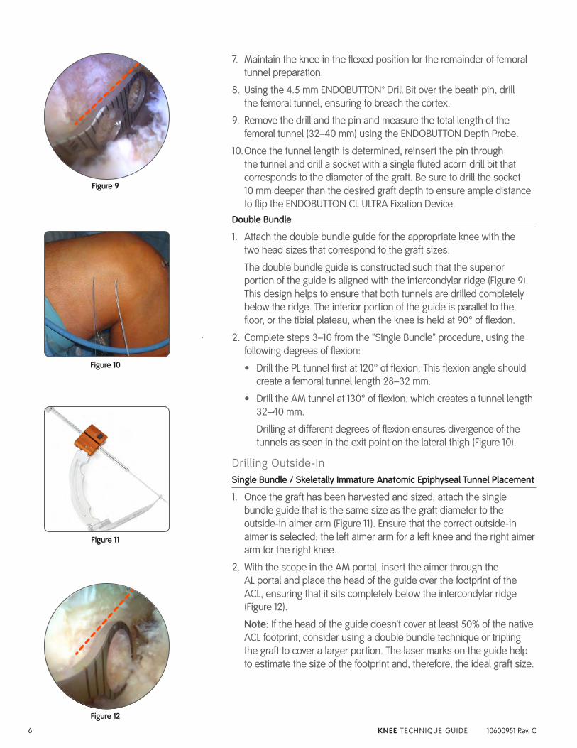
1. Attach the double bundle guide for the appropriate knee with the two head sizes that correspond to the graft sizes.
The double bundle guide is constructed such that the superior portion of the guide is aligned with the intercondylar ridge (Figure 9). This design helps to ensure that both tunnels are drilled completely below the ridge. The inferior portion of the guide is parallel to the floor, or the tibial plateau, when the knee is held at 90° of flexion.
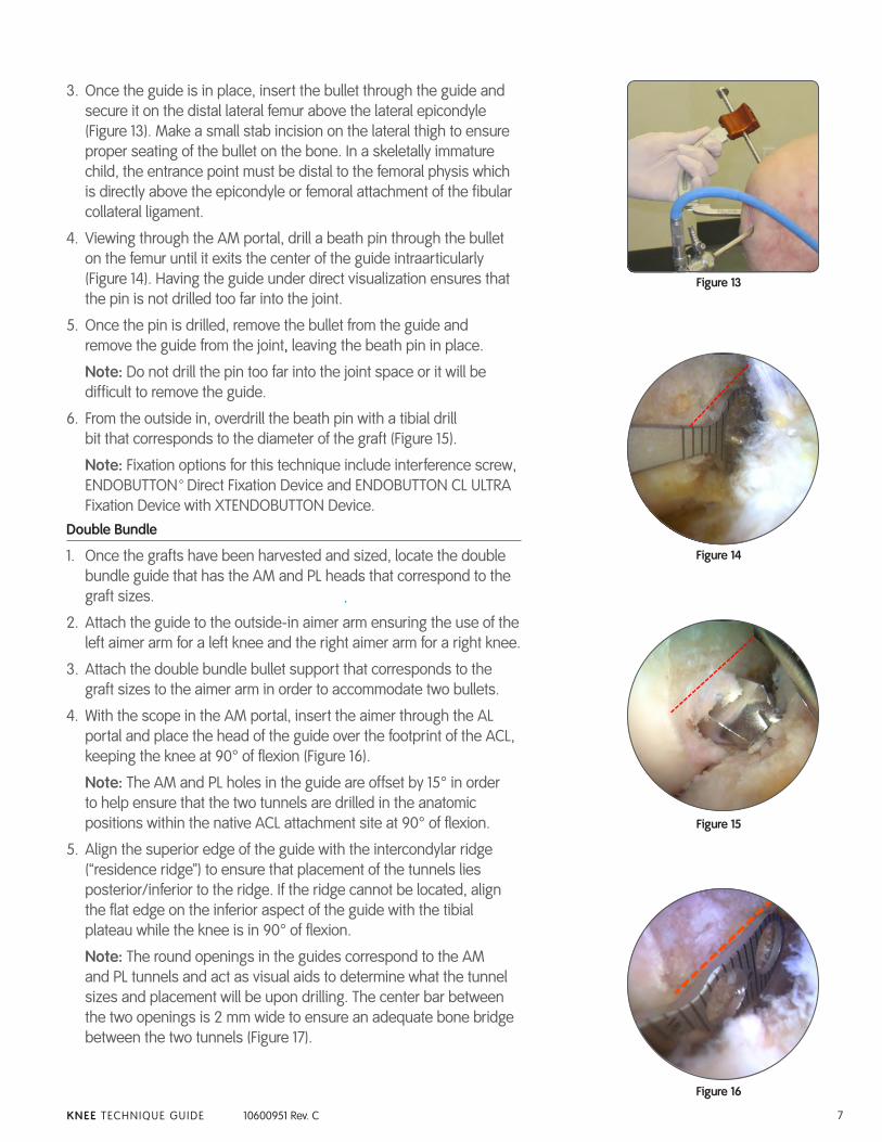
2. Complete steps 3–10 from the "Single Bundle" procedure, using the following degrees of flexion:
• Drill the PL tunnel first at 120° of flexion. This flexion angle should create a femoral tunnel length 28–32 mm.
• Drill the AM tunnel at 130° of flexion, which creates a tunnel length 32–40 mm.
Drilling at different degrees of flexion ensures divergence of the tunnels as seen in the exit point on the lateral thigh (Figure 10).
Drilling Outside-InSingle Bundle / Skeletally Immature Anatomic Epiphyseal Tunnel Placement
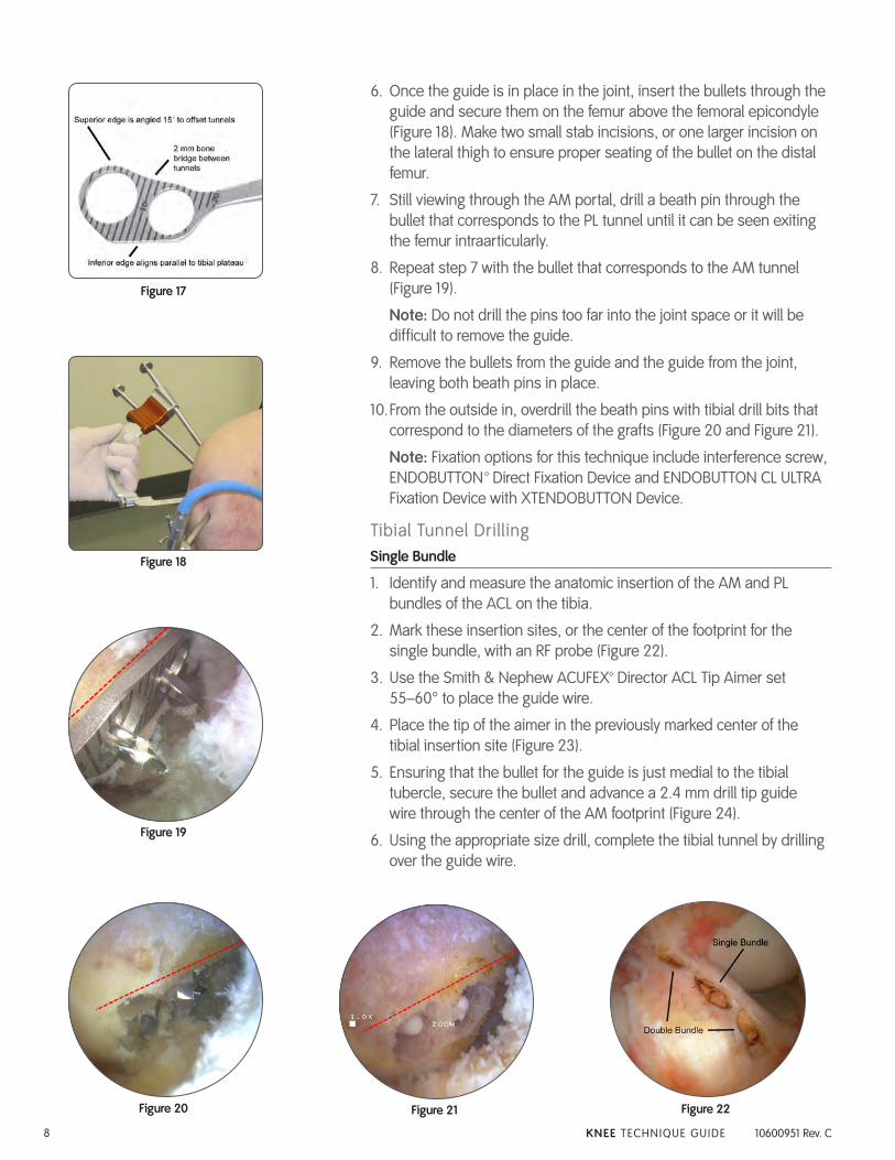
1. Once the graft has been harvested and sized, attach the single bundle guide that is the same size as the graft diameter to the outside-in aimer arm (Figure 11). Ensure that the correct outside-in aimer is selected; the left aimer arm for a left knee and the right aimer arm for the right knee.
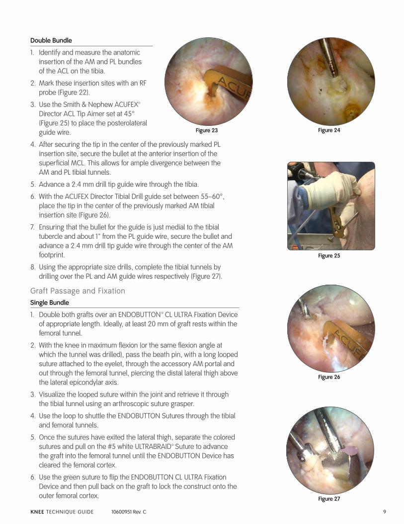
2. With the scope in the AM portal, insert the aimer through the AL portal and place the head of the guide over the footprint of the ACL, ensuring that it sits completely below the intercondylar ridge (Figure 12).
Note: If the head of the guide doesn’t cover at least 50% of the native ACL footprint, consider using a double bundle technique or tripling the graft to cover a larger portion. The laser marks on the guide help to estimate the size of the footprint and, therefore, the ideal graft size.
Figure 9
Figure 10
Figure 11
Figure 12
10600951C_ACUFEX _PINPOINT.indd 6 4/18/12 9:54 AM
7KNEE TECHNIQUE GUIDE 10600951 Rev. C
3. Once the guide is in place, insert the bullet through the guide and secure it on the distal lateral femur above the lateral epicondyle (Figure 13). Make a small stab incision on the lateral thigh to ensure proper seating of the bullet on the bone. In a skeletally immature child, the entrance point must be distal to the femoral physis which is directly above the epicondyle or femoral attachment of the fibular collateral ligament.
4. Viewing through the AM portal, drill a beath pin through the bullet on the femur until it exits the center of the guide intraarticularly (Figure 14). Having the guide under direct visualization ensures that the pin is not drilled too far into the joint.
5. Once the pin is drilled, remove the bullet from the guide and remove the guide from the joint, leaving the beath pin in place.
Note: Do not drill the pin too far into the joint space or it will be difficult to remove the guide.
6. From the outside in, overdrill the beath pin with a tibial drill bit that corresponds to the diameter of the graft (Figure 15).
Note: Fixation options for this technique include interference screw, ENDOBUTTON™ Direct Fixation Device and ENDOBUTTON CL ULTRA Fixation Device with XTENDOBUTTON Device.
Double Bundle
1. Once the grafts have been harvested and sized, locate the double bundle guide that has the AM and PL heads that correspond to the graft sizes.
2. Attach the guide to the outside-in aimer arm ensuring the use of the left aimer arm for a left knee and the right aimer arm for a right knee.
3. Attach the double bundle bullet support that corresponds to the graft sizes to the aimer arm in order to accommodate two bullets.
4. With the scope in the AM portal, insert the aimer through the AL portal and place the head of the guide over the footprint of the ACL, keeping the knee at 90° of flexion (Figure 16).
Note: The AM and PL holes in the guide are offset by 15° in order to help ensure that the two tunnels are drilled in the anatomic positions within the native ACL attachment site at 90° of flexion.
5. Align the superior edge of the guide with the intercondylar ridge (“residence ridge”) to ensure that placement of the tunnels lies posterior/inferior to the ridge. If the ridge cannot be located, align the flat edge on the inferior aspect of the guide with the tibial plateau while the knee is in 90° of flexion.
Note: The round openings in the guides correspond to the AM and PL tunnels and act as visual aids to determine what the tunnel sizes and placement will be upon drilling. The center bar between the two openings is 2 mm wide to ensure an adequate bone bridge between the two tunnels (Figure 17).
Figure 13
Figure 14
Figure 15
Figure 16
10600951C_ACUFEX _PINPOINT.indd 7 4/18/12 9:54 AM
8 KNEE TECHNIQUE GUIDE 10600951 Rev. C
6. Once the guide is in place in the joint, insert the bullets through the guide and secure them on the femur above the femoral epicondyle (Figure 18). Make two small stab incisions, or one larger incision on the lateral thigh to ensure proper seating of the bullet on the distal femur.
7. Still viewing through the AM portal, drill a beath pin through the bullet that corresponds to the PL tunnel until it can be seen exiting the femur intraarticularly.
8. Repeat step 7 with the bullet that corresponds to the AM tunnel (Figure 19).
Note: Do not drill the pins too far into the joint space or it will be difficult to remove the guide.
9. Remove the bullets from the guide and the guide from the joint, leaving both beath pins in place.
10. From the outside in, overdrill the beath pins with tibial drill bits that correspond to the diameters of the grafts (Figure 20 and Figure 21).
Note: Fixation options for this technique include interference screw, ENDOBUTTON™ Direct Fixation Device and ENDOBUTTON CL ULTRA Fixation Device with XTENDOBUTTON Device.
Tibial Tunnel DrillingSingle Bundle
1. Identify and measure the anatomic insertion of the AM and PL bundles of the ACL on the tibia.
2. Mark these insertion sites, or the center of the footprint for the single bundle, with an RF probe (Figure 22).
3. Use the Smith & Nephew ACUFEX™ Director ACL Tip Aimer set 55–60° to place the guide wire.
4. Place the tip of the aimer in the previously marked center of the tibial insertion site (Figure 23).
5. Ensuring that the bullet for the guide is just medial to the tibial tubercle, secure the bullet and advance a 2.4 mm drill tip guide wire through the center of the AM footprint (Figure 24).
6. Using the appropriate size drill, complete the tibial tunnel by drilling over the guide wire.
Figure 19
Figure 20 Figure 21 Figure 22
Figure 18
Figure 17
10600951C_ACUFEX _PINPOINT.indd 8 4/18/12 9:54 AM
9KNEE TECHNIQUE GUIDE 10600951 Rev. C
Double Bundle
1. Identify and measure the anatomic insertion of the AM and PL bundles of the ACL on the tibia.
2. Mark these insertion sites with an RF probe (Figure 22).
3. Use the Smith & Nephew ACUFEX™ Director ACL Tip Aimer set at 45° (Figure 25) to place the posterolateral guide wire.
4. After securing the tip in the center of the previously marked PL insertion site, secure the bullet at the anterior insertion of the superficial MCL. This allows for ample divergence between the AM and PL tibial tunnels.
5. Advance a 2.4 mm drill tip guide wire through the tibia.
6. With the ACUFEX Director Tibial Drill guide set between 55–60°, place the tip in the center of the previously marked AM tibial insertion site (Figure 26).
7. Ensuring that the bullet for the guide is just medial to the tibial tubercle and about 1" from the PL guide wire, secure the bullet and advance a 2.4 mm drill tip guide wire through the center of the AM footprint.
8. Using the appropriate size drills, complete the tibial tunnels by drilling over the PL and AM guide wires respectively (Figure 27).
Graft Passage and FixationSingle Bundle
1. Double both grafts over an ENDOBUTTON™ CL ULTRA Fixation Device of appropriate length. Ideally, at least 20 mm of graft rests within the femoral tunnel.
2. With the knee in maximum flexion (or the same flexion angle at which the tunnel was drilled), pass the beath pin, with a long looped suture attached to the eyelet, through the accessory AM portal and out through the femoral tunnel, piercing the distal lateral thigh above the lateral epicondylar axis.
3. Visualize the looped suture within the joint and retrieve it through the tibial tunnel using an arthroscopic suture grasper.
4. Use the loop to shuttle the ENDOBUTTON Sutures through the tibial and femoral tunnels.
5. Once the sutures have exited the lateral thigh, separate the colored sutures and pull on the #5 white ULTRABRAID™ Suture to advance the graft into the femoral tunnel until the ENDOBUTTON Device has cleared the femoral cortex.
6. Use the green suture to flip the ENDOBUTTON CL ULTRA Fixation Device and then pull back on the graft to lock the construct onto the outer femoral cortex.
Figure 23 Figure 24
Figure 25
Figure 26
Figure 27
10600951C_ACUFEX _PINPOINT.indd 9 4/18/12 9:54 AM
10 KNEE TECHNIQUE GUIDE 10600951 Rev. C
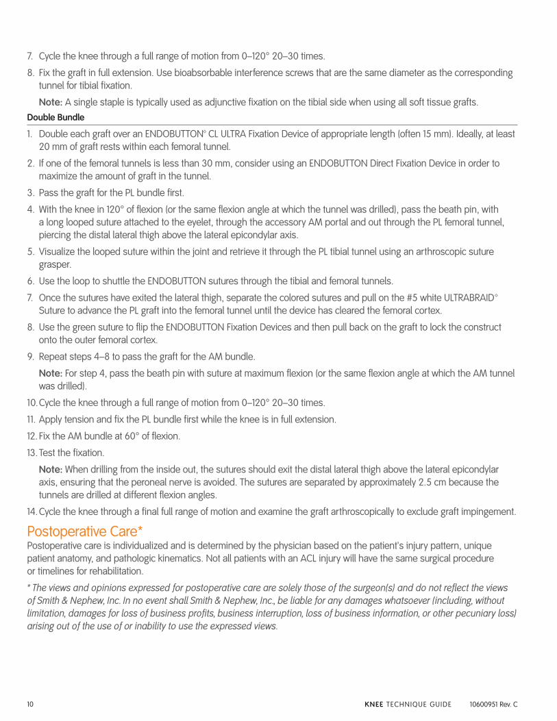
7. Cycle the knee through a full range of motion from 0–120° 20–30 times.
8. Fix the graft in full extension. Use bioabsorbable interference screws that are the same diameter as the corresponding tunnel for tibial fixation.
Note: A single staple is typically used as adjunctive fixation on the tibial side when using all soft tissue grafts. Double Bundle
1. Double each graft over an ENDOBUTTON™ CL ULTRA Fixation Device of appropriate length (often 15 mm). Ideally, at least 20 mm of graft rests within each femoral tunnel.
2. If one of the femoral tunnels is less than 30 mm, consider using an ENDOBUTTON Direct Fixation Device in order to maximize the amount of graft in the tunnel.
3. Pass the graft for the PL bundle first.
4. With the knee in 120° of flexion (or the same flexion angle at which the tunnel was drilled), pass the beath pin, with a long looped suture attached to the eyelet, through the accessory AM portal and out through the PL femoral tunnel, piercing the distal lateral thigh above the lateral epicondylar axis.
5. Visualize the looped suture within the joint and retrieve it through the PL tibial tunnel using an arthroscopic suture grasper.
6. Use the loop to shuttle the ENDOBUTTON sutures through the tibial and femoral tunnels.
7. Once the sutures have exited the lateral thigh, separate the colored sutures and pull on the #5 white ULTRABRAID™ Suture to advance the PL graft into the femoral tunnel until the device has cleared the femoral cortex.
8. Use the green suture to flip the ENDOBUTTON Fixation Devices and then pull back on the graft to lock the construct onto the outer femoral cortex.
9. Repeat steps 4–8 to pass the graft for the AM bundle.
Note: For step 4, pass the beath pin with suture at maximum flexion (or the same flexion angle at which the AM tunnel was drilled).
10. Cycle the knee through a full range of motion from 0–120° 20–30 times.
11. Apply tension and fix the PL bundle first while the knee is in full extension.
12. Fix the AM bundle at 60° of flexion.
13. Test the fixation.
Note: When drilling from the inside out, the sutures should exit the distal lateral thigh above the lateral epicondylar axis, ensuring that the peroneal nerve is avoided. The sutures are separated by approximately 2.5 cm because the tunnels are drilled at different flexion angles.
14. Cycle the knee through a final full range of motion and examine the graft arthroscopically to exclude graft impingement.
Postoperative Care*Postoperative care is individualized and is determined by the physician based on the patient's injury pattern, unique patient anatomy, and pathologic kinematics. Not all patients with an ACL injury will have the same surgical procedure or timelines for rehabilitation.
* The views and opinions expressed for postoperative care are solely those of the surgeon(s) and do not reflect the views of Smith & Nephew, Inc. In no event shall Smith & Nephew, Inc., be liable for any damages whatsoever (including, without limitation, damages for loss of business profits, business interruption, loss of business information, or other pecuniary loss) arising out of the use of or inability to use the expressed views.
10600951C_ACUFEX _PINPOINT.indd 10 4/18/12 9:54 AM

10600951C_ACUFEX _PINPOINT.indd 11 4/18/12 9:54 AM
ORDERING INFORMATION
To order the instruments used in this technique, call +1 800 343 5717 in the U.S. or contact an authorized Smith & Nephew representative.
Prior to performing this technique, consult the Instructions for Use documentation provided with individual components – including indications, contraindications, warnings, cautions, and instructions.
EndoscopySmith & Nephew, Inc.150 Minuteman RoadAndover, MA 01810USA
www.smith-nephew.com+1 978 749 1000+1 978 749 1108 Fax+1 800 343 5717 U.S. Customer Service
Courtesy of Smith & Nephew, Inc.
™Trademark of Smith & Nephew. Certain marks registered U.S. Patent & Trademark Office. ©2012 Smith & Nephew, Inc. All rights reserved. 04/2012 10600951 Rev. C
Reference # Description
72203454 ACUFEX™ PINPOINT Anatomic ACL Guide System
System Includes:
72203433 Single Bundle Guide, 6 mm
72203434 Single Bundle Guide, 7 mm
72203435 Single Bundle Guide, 8 mm
72203436 Single Bundle Guide, 9 mm
72203437 Single Bundle Guide, 10 mm
72203438 Double Bundle Guide, Left, 5–6 mm
72203439 Double Bundle Guide, Left, 5–7 mm
72203440 Double Bundle Guide, Left, 6–7 mm
72203441 Double Bundle Guide, Left, 6–8 mm
72203442 Double Bundle Guide, Left, 7–8 mm
72203443 Double Bundle Guide, Right, 5–6 mm
72203444 Double Bundle Guide, Right, 5–7 mm
72203445 Double Bundle Guide, Right, 6–7 mm
72203446 Double Bundle Guide, Right, 6–8 mm
72203447 Double Bundle Guide, Right, 7–8mm
72203425 Outside-In Aimer Arm, Left
72203426 Outside-In Aimer Arm, Right
72203432 Inside-Out Handle
72203427 Double Bundle Bullet Support, 5–6 mm
72203428 Double Bundle Bullet Support, 5–7 mm
72203429 Double Bundle Bullet Support, 6–7 mm
72203430 Double Bundle Bullet Support, 6–8 mm
72203431 Double Bundle Bullet Support, 7–8 mm
72203448 Anatomic ACL Guide Sterilization Tray
72203453 ACUFEX Insertion Site Marking Awl, 45°
72203450 Bullet 4 point – 6.5" (2 required)
Reference # Description
72203452 ACUFEX PINPOINT Anatomic ACL Single Bundle Guide System
System Includes:
72203433 Single Bundle Guide, 6 mm
72203434 Single Bundle Guide, 7 mm
72203435 Single Bundle Guide, 8 mm
72203436 Single Bundle Guide, 9 mm
72203437 Single Bundle Guide, 10 mm
72203425 Outside-In Aimer Arm, Left
72203426 Outside-In Aimer Arm, Right
72203432 Inside-Out Handle
72203451 Single Bundle Sterilization Tray
72203453 ACUFEX Insertion Site Marking Awl, 45°
72203450 Bullet 4 point – 6.5" (1 required)
CAUTION: U.S. Federal law restricts these devices to sale by or on the order of a physician.
10600951C_ACUFEX _PINPOINT.indd 12 4/18/12 9:54 AM


![[164] pinpoint](https://img.pdfslide.net/doc/110x75/587065dc1a28ab48378b4f79/164-pinpoint.jpg)