Embed Size (px)
Citation preview
B.E/B.Tech DEGREE EXAMINATION, NOV/DEC 2008
Third Semester
Mechanical Engineering
ME 2203/ME 35 / 10122 ME 404 / ME 1202 A / 080120010 – KINEMATICS OF MACHINERY
(Regulation 2008)
PART A
1. Define DOF of a Mechanism.
The DoF for a mechanism is defined as the number of coordinates or variables required to be specified such that the position and orientation of all the members of the mechanism can be stated as a function of time.
2. State Grubbler’s Criterion for planar mechanisms.
The following equation is used to describe mobility in 2D or planar systems:
M = 3(N-1) – 2 f1 – f2
Where,n = total number of links
M = DOF
f1 = number of 1DOF joints
f 2 = number of 2 DOF joints
This is known as GRUBLER’S EQUATION and is for mobility of planar systems.
M = 0 - Motion impossible - statically determinate
M = 1 - Single input /monitoring necessary
M = 2 - Double input/output necessary
M = -1 - Statically indeterminate structure
3. Define “Actual Mechanical Advantage”
It is defined as the ratio of the output torque, supplied by the driven link, to the input torque, required to be supplied to the driver link.
4. How the direction of coriolis component of acceleration is determined?
The direction of coriolis component of acceleration is obtained by rotating v, at 90°, about its origin in the same direction as that of ω.
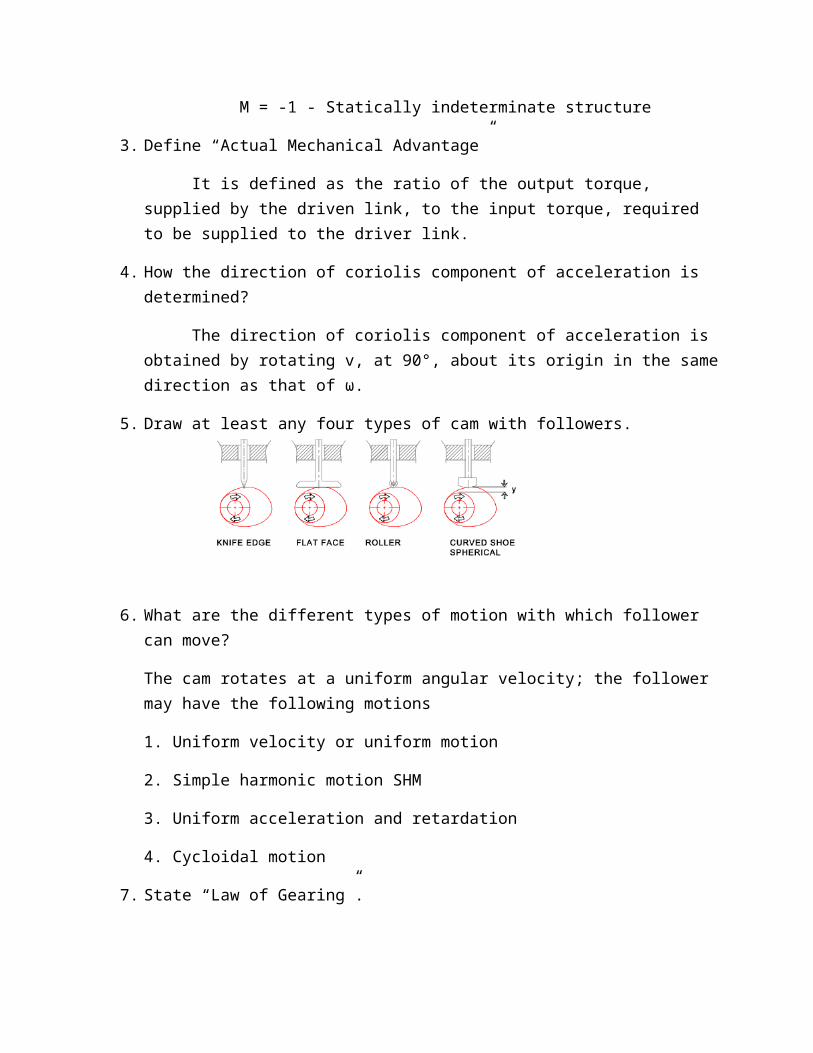
5. Draw at least any four types of cam with followers.
6. What are the different types of motion with which follower can move?
The cam rotates at a uniform angular velocity; the follower may have the following motions
1. Uniform velocity or uniform motion
2. Simple harmonic motion SHM
3. Uniform acceleration and retardation
4. Cycloidal motion
7. State “Law of Gearing”.
The common normal at the point of contact between a pair of teeth must always pass through the pitch point for all positions of the mating gears.
8. What are the various types of torques in an epicyclic gear train?
1) Impart torque on the driving member.
2) Resisting or holding torque on the driven member.
3) Holding or braking torque on the fixed member.
9. How Centrifugal tension affects the power transmission in belt drive?
During operation, as the belt passes over a pulley the centrifugal effect due to its weight tends to lift the belt from the pulley surface. This reduces the normal reaction and hence the frictional resistance. The centrifugal force produces additional tension in the belt.
10. Define the term “Limiting Friction”
This maximum value of frictional force, which comes into play, when a body just begins to slide over the surface of the other body, is known as limiting force of friction or simply limiting friction
PART B
11 (a) (i) Explain the following mechanism in kinematic point of view
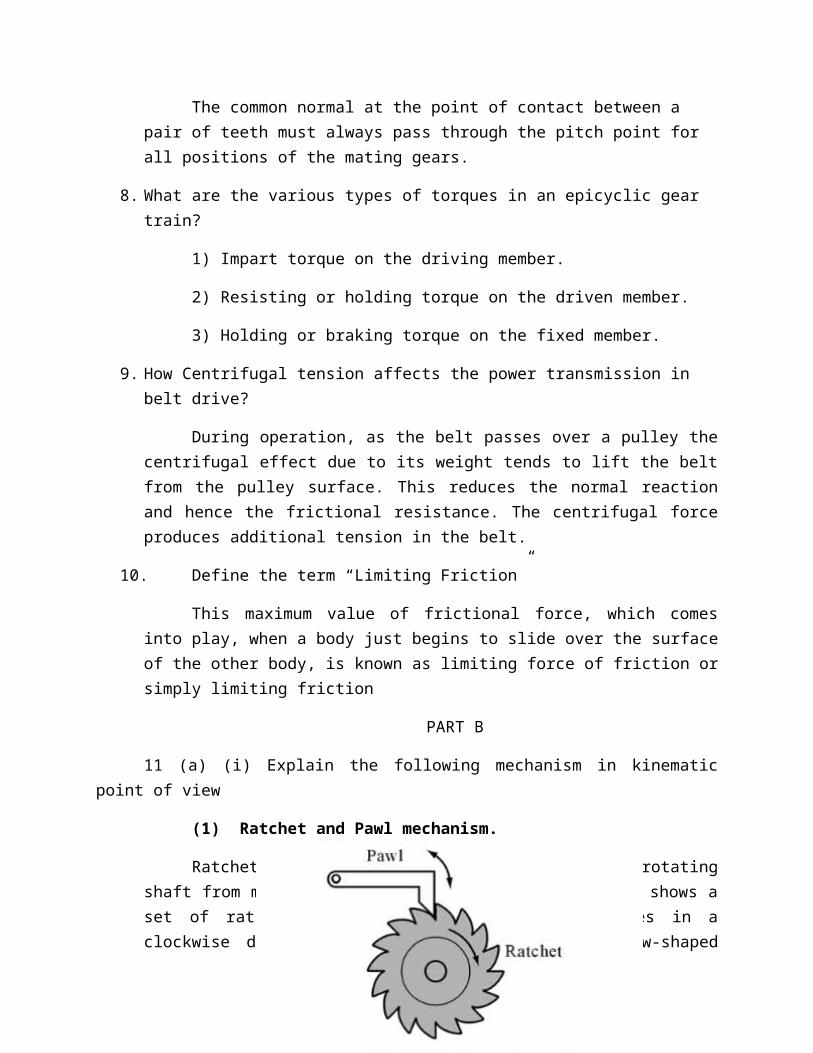
(1) Ratchet and Pawl mechanism.
Ratchet and pawl can be used to prevent the rotating shaft from moving in the opposite direction. Fig. 1 shows a set of ratchet and pawl. When the ratchet moves in a clockwise direction, the pawl will let every saw-shaped tooth pass. However, if the ratchet moves in an anti-clockwise direction, the pawl will be locked into the base of the ratchet so that the ratchet cannot move. One typical example is the straightening of the volleyball mesh with the use of ratchet mechanism.
` Fig. 1 Ratchet and pawl
Another application of ratchet and pawl is to change the swinging action of the pawl into a periodical and uni-directional rotary motion (Fig. 2). This can be applied to the metal sawing machine.
Fig. 2 Pawl driving the ratchet
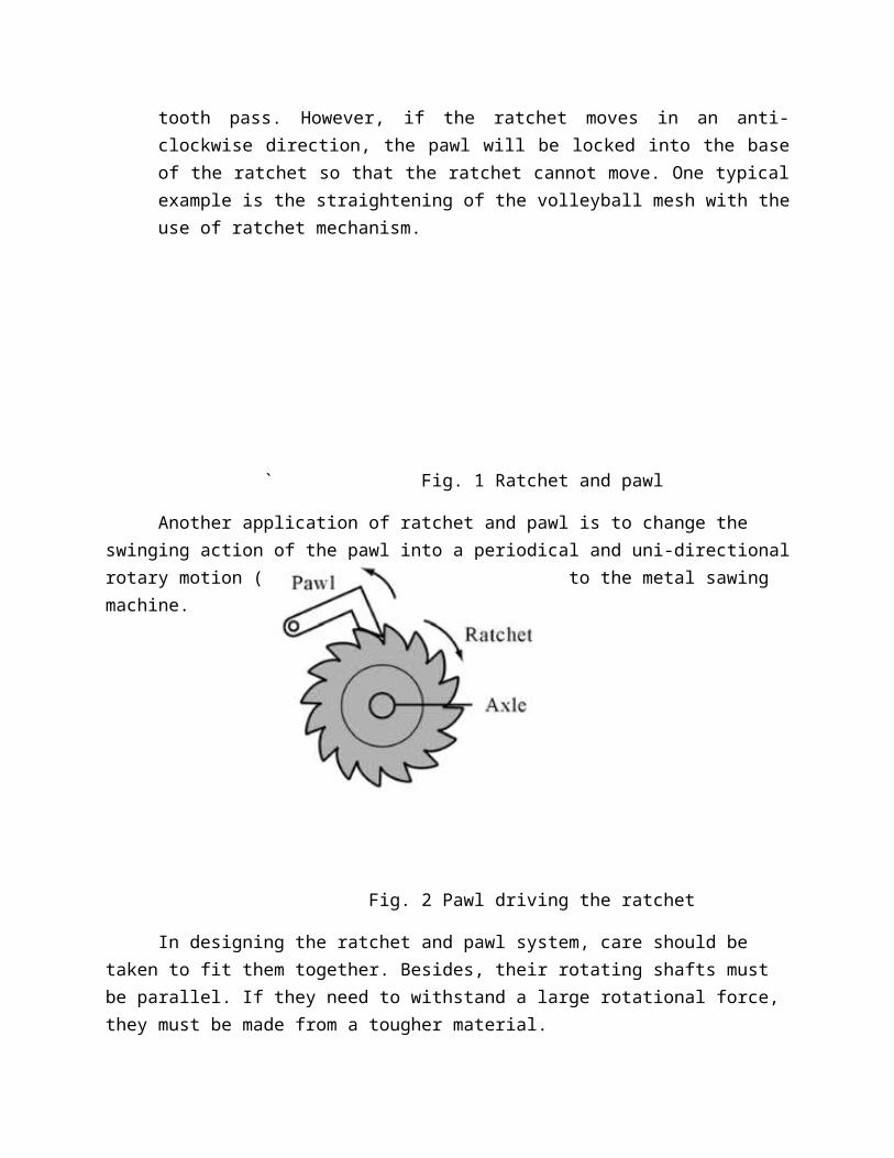
In designing the ratchet and pawl system, care should be taken to fit them together. Besides, their rotating shafts must be parallel. If they need to withstand a large rotational force, they must be made from a tougher material.
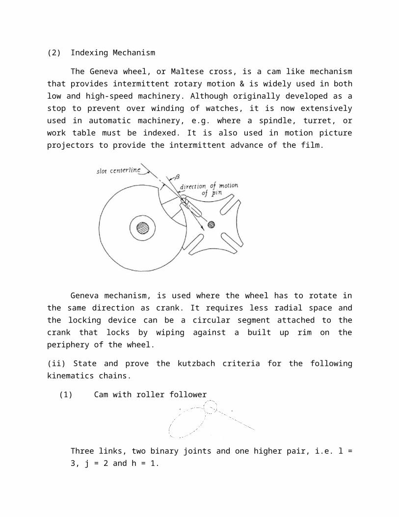
(2) Indexing Mechanism
The Geneva wheel, or Maltese cross, is a cam like mechanism that provides intermittent rotary motion & is widely used in both low and high-speed machinery. Although originally developed as a stop to prevent over winding of watches, it is now extensively used in automatic machinery, e.g. where a spindle, turret, or work table must be indexed. It is also used in motion picture projectors to provide the intermittent advance of the film.
Geneva mechanism, is used where the wheel has to rotate in the same direction as crank. It requires less radial space and the locking device can be a circular segment attached to the crank that locks by wiping against a built up rim on the periphery of the wheel.
(ii) State and prove the kutzbach criteria for the following kinematics chains.
(1) Cam with roller follower
Three links, two binary joints and one higher pair, i.e. l = 3, j = 2 and h = 1.
∴ n = 3 (3 – 1) – 2 × 2 – 1 = 1
(2) Three bar chain
The mechanism, as shown in Fig. 1 has three links and three binary joints, i.e. l = 3 and j = 3.
∴ n = 3 (3 – 1) – 2 × 3 = 0
(or)
(b) (i) Sketch and explain any three inversions of a double slider crank chain
The following three inversions of a double slider crank chain are important from the subject point of view:
1. Elliptical trammels. It is an instrument used for drawing ellipses. This inversion is obtained by fixing the slotted plate (link 4), as shown in Fig. 1(a). The fixed plate or link 4 has two straight grooves cut in it, at right angles to each other. The link 1 and link 3, are known as sliders and form sliding pairs with link 4. The link AB (link 2) is a bar which forms turning pair with links 1 and 3. When the links 1 and 3 slide along their respective grooves, any point on the link 2 such as P traces out an ellipse on the surface of link 4, as shown in Fig.1(a).
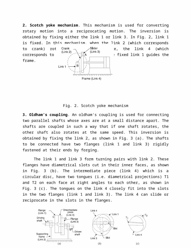
2. Scotch yoke mechanism. This mechanism is used for converting rotary motion into a reciprocating motion. The inversion is obtained by fixing either the link 1 or link 3. In Fig. 2, link 1 is fixed. In this mechanism, when the link 2 (which corresponds to crank) rotates about B as centre, the link 4 (which corresponds to a frame) reciprocates. The fixed link 1 guides the frame.
Fig. 2. Scotch yoke mechanism
3. Oldham’s coupling. An oldham's coupling is used for connecting two parallel shafts whose axes are at a small distance apart. The shafts are coupled in such a way that if one shaft rotates,

the other shaft also rotates at the same speed. This inversion is obtained by fixing the link 2, as shown in Fig. 3 (a). The shafts to be connected have two flanges (link 1 and link 3) rigidly fastened at their ends by forging.
The link 1 and link 3 form turning pairs with link 2. These flanges have diametrical slots cut in their inner faces, as shown in Fig. 3 (b). The intermediate piece (link 4) which is a circular disc, have two tongues (i.e. diametrical projections) T1 and T2 on each face at right angles to each other, as shown in Fig. 3 (c). The tongues on the link 4 closely fit into the slots in the two flanges (link 1 and link 3). The link 4 can slide or reciprocate in the slots in the flanges.
Fig. 3. Oldham’s coupling
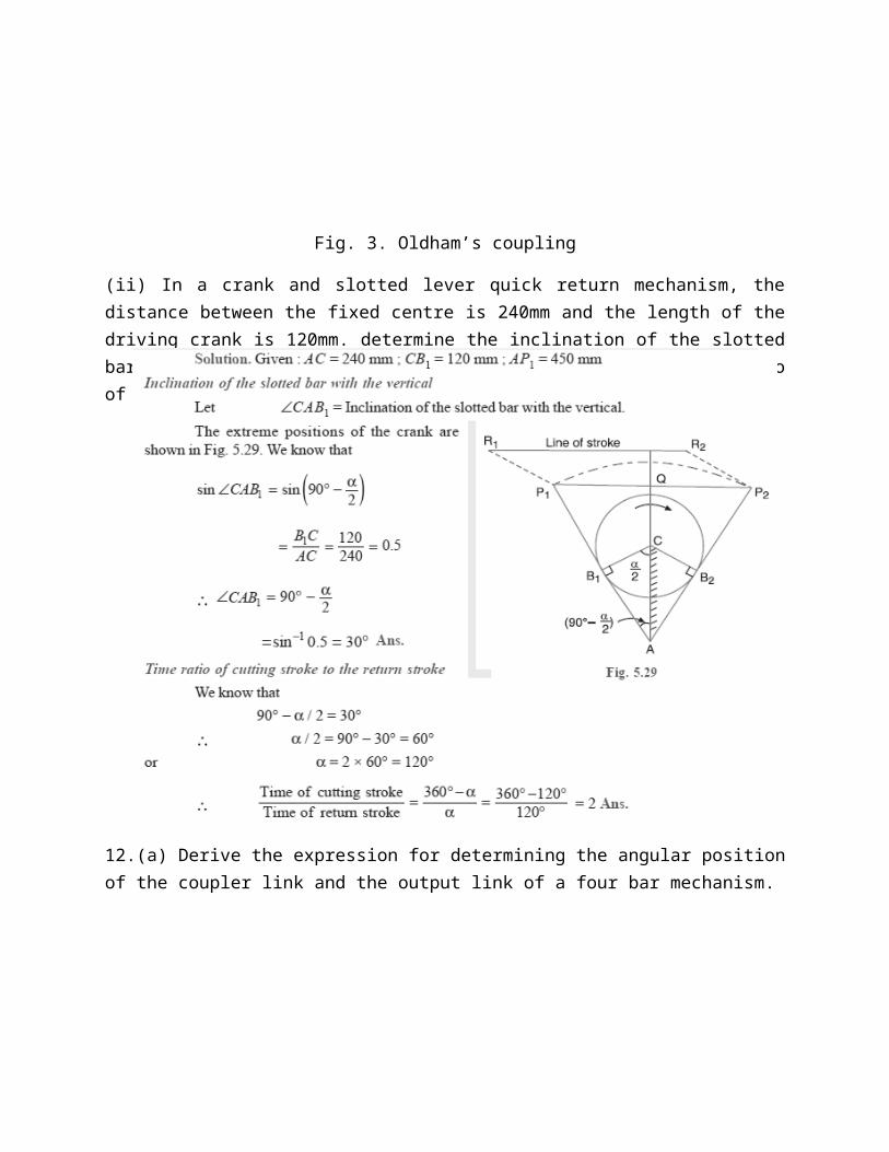
(ii) In a crank and slotted lever quick return mechanism, the distance between the fixed centre is 240mm and the length of the driving crank is 120mm. determine the inclination of the slotted bar with the vertical in the extreme position and the time ratio of cutting stroke to the return stroke.
12.(a) Derive the expression for determining the angular position of the coupler link and the output link of a four bar mechanism.
(or)
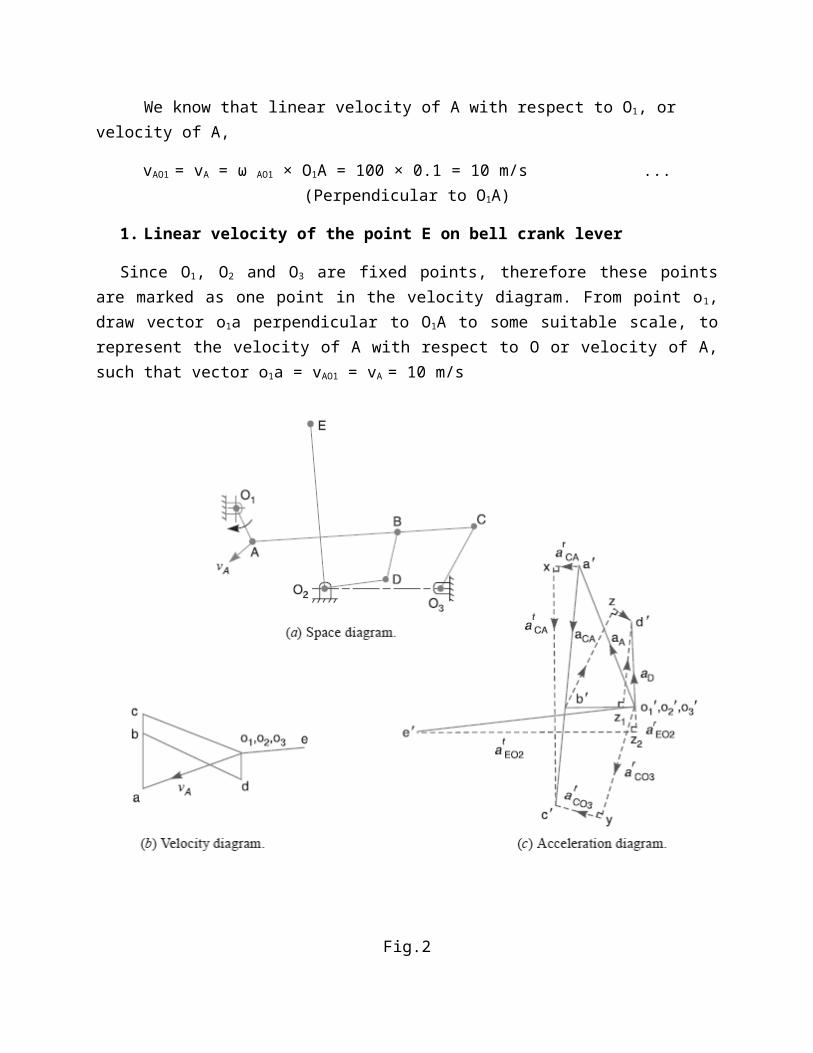
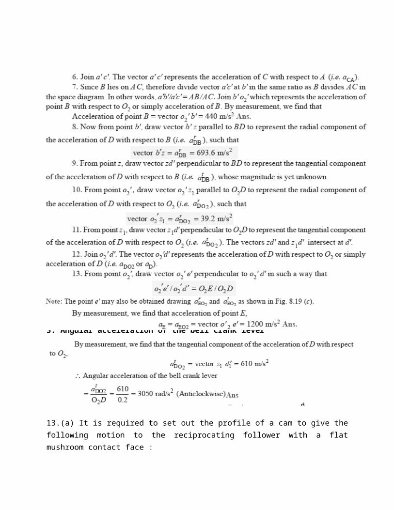
(b) The mechanism of a warping machine, as shown in Fig.1, has the dimensions as follows:O 1A = 100 mm; AC = 700 mm ; BC = 200 mm ; BD = 150 mm ; O2D = 200 mm ; O2E = 400 mm ; O3C = 200 mm. The crank O1A rotates at a uniform speed of 100 rad/s. For the given configuration, determine:
1. Linear velocity of the point E on the bell crank lever,
2. Acceleration of the points E and B, and
3. Angular acceleration of the bell crank lever.
Fig.1
Given : ωAO1 = 100 rad/s ; O1A = 100 mm = 0.1 m
We know that linear velocity of A with respect to O1, or velocity of A,
vAO1 = vA = ω AO1 × O1A = 100 × 0.1 = 10 m/s ...(Perpendicular to O1A)
1. Linear velocity of the point E on bell crank lever
Since O1, O2 and O3 are fixed points, therefore these points are marked as one point in the velocity diagram. From point o1, draw vector o1a perpendicular to O1A to some suitable scale, to

represent the velocity of A with respect to O or velocity of A, such that vector o1a = vAO1 = vA = 10 m/s
Fig.2
From point a, draw vector ac perpendicular to AC to represent the velocity of C with respect to A (i.e. vCA) and from point o3 draw vector o3c perpendicular to O3C to represent the velocity of C with respect to O3 or simply velocity of C (i.e. vC). The vectors ac and o3c intersect at point c.
Since B lies on AC, therefore divide vector ac at b in the same ratio as B divides AC in the space diagram. In other words, ab/ac = AB/AC
. From point b, draw vector bd perpendicular to BD to represent the velocity of D with respect to B (i.e. vDB), and from point o2 draw vector o2d perpendicular to O2D to represent the velocity of D with respect to O2 or simply velocity of D (i.e. vD). The vectors bd and o2d intersect at d.
5. From point o2, draw vector o2eperpendicular to vector o2d in such a way that

o2e/o2d = O2E/O2D
By measurement, we find that velocity of point C with respect to A,
vCA = vector ac = 7 m/s
Velocity of point C with respect to O3,
vCO3 = vC = vector o3c = 10 m/s
Velocity of point D with respect to B,
vDB = vector bd = 10.2 m/s
Velocity of point D with respect to O2,
vDO2 = vD = vector o2d = 2.8 m/s
and velocity of the point E on the bell crank lever,
vE = vEO2 = vector o2e = 5.8 m/s Ans.
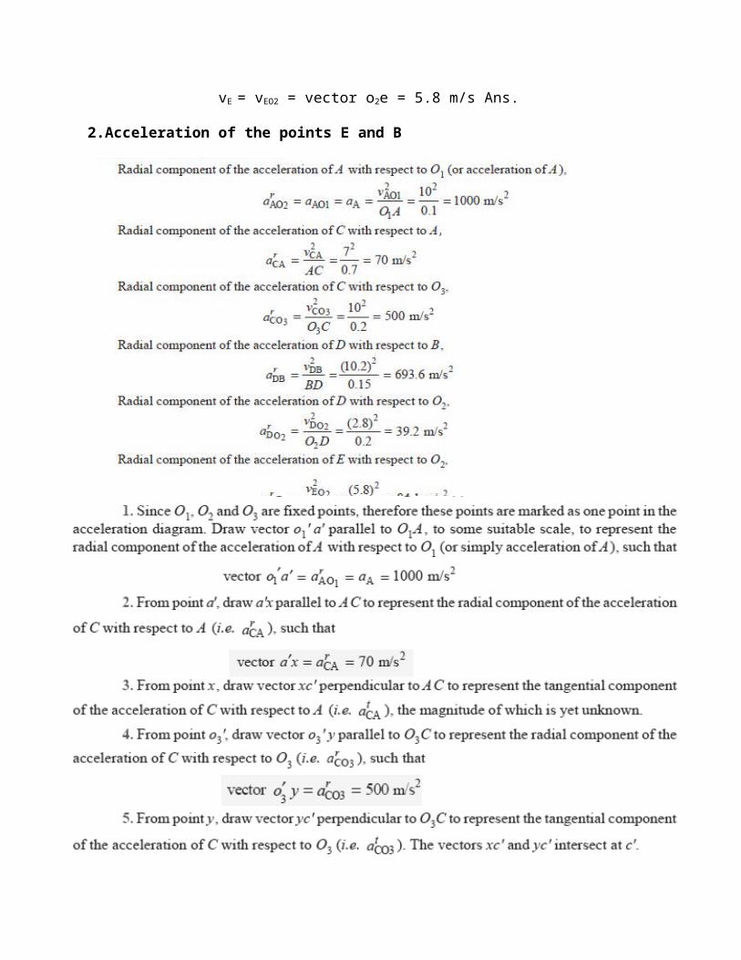
2.Acceleration of the points E and B
2
3. Angular acceleration of the bell crank lever
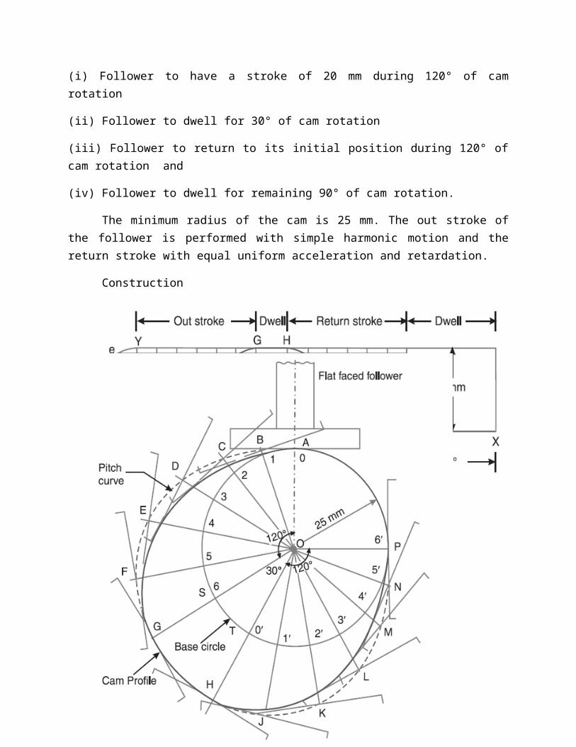
13.(a) It is required to set out the profile of a cam to give the following motion to the reciprocating follower with a flat mushroom contact face :
(i) Follower to have a stroke of 20 mm during 120° of cam rotation
(ii) Follower to dwell for 30° of cam rotation
(iii) Follower to return to its initial position during 120° of cam rotation and
(iv) Follower to dwell for remaining 90° of cam rotation.
The minimum radius of the cam is 25 mm. The out stroke of the follower is performed with simple harmonic motion and the return stroke with equal uniform acceleration and retardation.
Construction
(or)
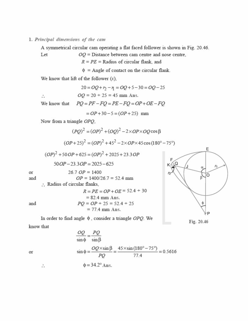
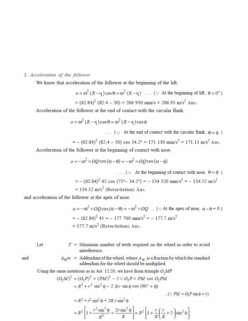
(b) A symmetrical circular cam operating a flat-faced follower has the following particulars : Minimum radius of the cam = 30 mm ; Total lift = 20 mm ; Angle of lift = 75° ; Nose radius = 5 mm ; Speed = 600 r.p.m. Find :
1. the principal dimensions of the cam, and
2. the acceleration of the follower at the beginning of the lift, at the end of contact with the circular flank , at the beginning of contact with nose and at the apex of the nose.
14. (a) (i) Derive an expression for minimum number of teeth on the wheel in order to avoid interference
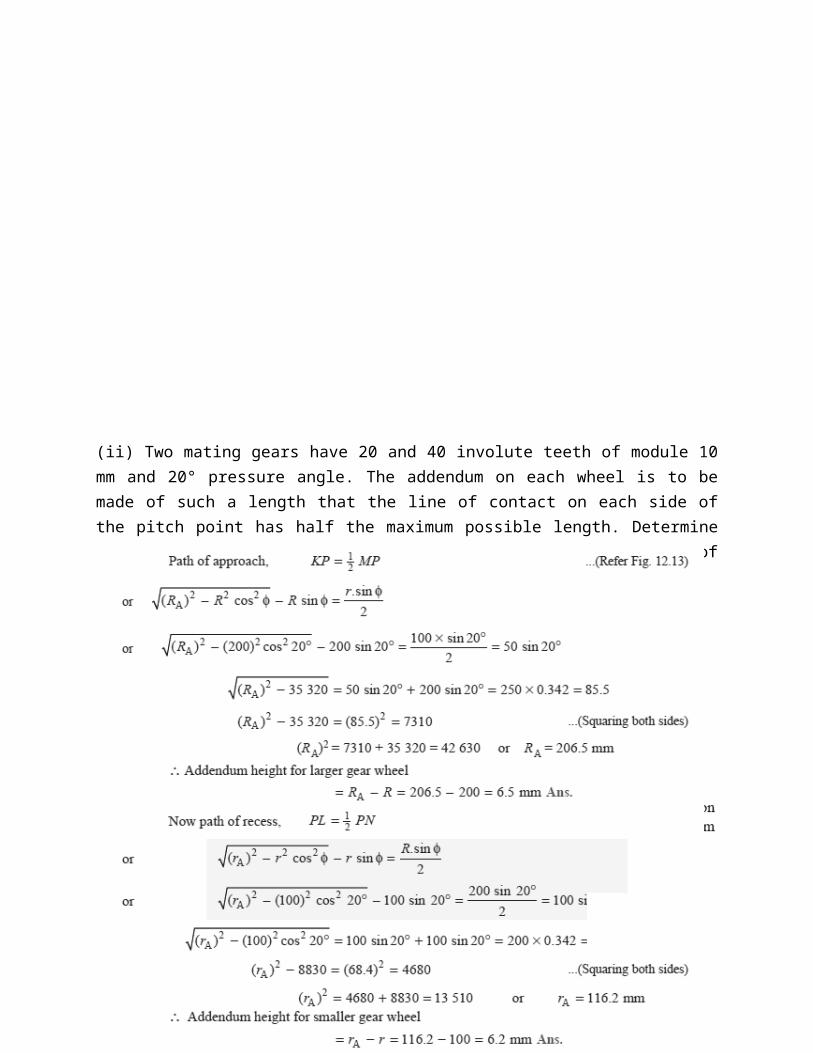
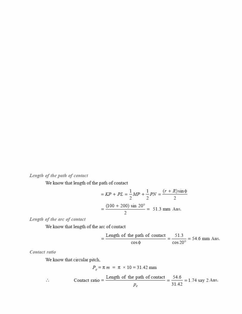
(ii) Two mating gears have 20 and 40 involute teeth of module 10 mm and 20° pressure angle. The addendum on each wheel is to be made of such a length that the line of contact on each side of the pitch point has half the maximum possible length. Determine the addendum height for each gear wheel, length of the path of contact, arc of contact and contact ratio.
(or)
(b).(i) Explain the procedure adopted designing the spur wheels.
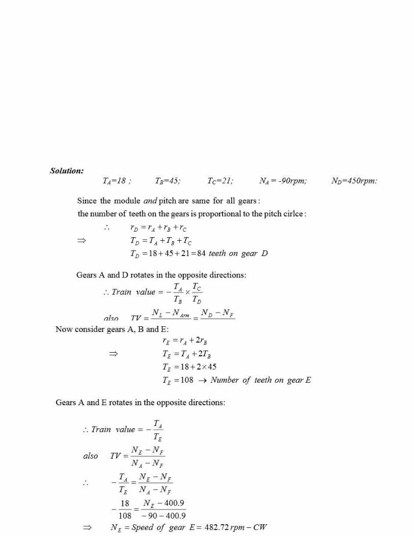
(ii) In a compound epicyclic gear train as shown in the figure, has gears A and an annular gears D & E free to rotate on the axis P. B and C is a compound gear rotate about axis Q. Gear A rotates at 90 rpm CCW and gear D rotates at 450 rpm CW. Find the speed and direction of rotation of arm F and gear E. Gears A,B and C are having 18, 45 and 21 teeth respectively. All gears having same module and pitch.

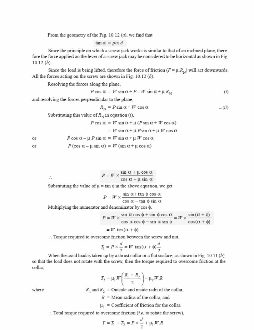
15.(a) (i) Derive an expression for the torque required to lift a load by a screw jack, if l is the length of the arm.
(ii) A leather faced conical clutch has a cone angle of 30º. If the intensity of pressure between the contact surfaces is limited to 0.35 N/mm2 and the breadth of the conical surface is not to exceed one-third of the mean radius, find the dimensions of the contact surfaces to transmit 22.5 kW at 2000 r.p.m. Assume uniform rate of wear and take coefficient of friction as 0.15.

Solution. Given : 2 α = 30º or α = 15º ; pn = 0.35 N/mm2; b = R/3 ; P = 22.5 kW =
22.5 × 10³ W ; N = 2000 r.p.m. or ω = 2 π × 2000/60 = 209.5 rad/s ; μ = 0.15
Let r1 = Outer radius of the contact surface in mm,
(or)
(b) (i) A compressor, requiring 90 kW is to run at about 250 r.p.m. The drive is by V-belts from an electric motor running at 750 r.p.m. The diameter of the pulley on the compressor shaft must not be greater than 1 metre while the centre distance between the pulleys is limited to 1.75 metre.
The belt speed should not exceed 1600 m/min. Determine the number of V-belts required to transmit the power if each belt has a cross sectional area of 375 mm2, density 1000 kg/m3 and an allowable tensile stress of 2.5 MPa. The groove angle of the pulley is 35°. The coefficient of friction between the belt and the pulley is 0.25. Calculate also the length required of each belt.
Solution.
Given : P = 90 kW ; N2 = 250 r.p.m. ; N1 = 750 r.p.m. ; d2 = 1 m ; x = 1.75 m ;
v = 1600 m/min = 26.67 m/s ; a = 375 mm2 = 375 × 10–6 m2 ; ρ = 1000 kg/m3 ;
σ = 2.5 MPa = 2.5 × 10⁶ N/m2 ; 2 β = 35° or β = 17.5° ; μ = 0.25

(ii) Derive an expression for braking torque on the drum of simple band brake
A band brake consists of a flexible band of leather, one or more ropes,or a steel lined with friction material, which embraces a part of the circumference of the drum. A band brake, as shown in Fig. 19.11, is called a simple band brake in which one end of the band is attached to a fixed pin or fulcrum of the lever while the other end is attached to the lever at a distance b from the fulcrum. When a force P is applied to the lever at C, the lever turns about the fulcrum pin O and tightens the band on the drum and hence the brakes are applied. The friction between the band and the drum provides the braking force. The force P on the lever at C may be determined as discussed below :
Let T1 = Tension in the tight side of the band,
T2 = Tension in the slack side of the band,
θ = Angle of lap (or embrace) of the band on the drum,
μ = Coefficient of friction between the band and the drum,
r = Radius of the drum,
t = Thickness of the band, and
re = Effective radius of the drum