Embed Size (px)
Citation preview
SERVICEMANUAL
FOREWORD
This manual includes procedure for mainte-nance, adjustment, service operation and re-moval and installation of components.
All information, illustrations and specificationscontained in this manual are based on the latestproduct information available at the time ofmanual approval.
The right is reserved to make changes at anytime without notice.
SECTION INDEX
DRIVE LINE/AXLE
BRAKES
TRANSMISSION
STEERING
HVAC(HEATING, VENTILATION,AND AIR CONDITIONING)
RESTRAINTS
BODY AND ACCESSORIES
3
4
5
6
7
8
9
ENGINE
SUSPENSION
1
2
FRONT MATTER
GENERAL INFORMATION
0A
0B
INCHON, KOREA
DAEWOO MOTOR CO., LTD.
KORANDO

PERSONAL INJURY CAUTION
Appropriate service methods and proper repair procedure are essentialfor the safe, reliable operation of all motor vehicles, as well as for thepersonal safety of the person doing the repair. There are manyvariations in procedures, techniques, tools and parts for servicingvehicles, as well as in the skills of the people doing the work. Thismanual cannot possibly anticipate all such variations and provide adviceor precautions for each. Anyone who deviates from the instructionsprovided in this manual must ensure their own safety and preservethe safety and integrity of the vehicle. The following list contains generalprecautions that should always be followed while working on a vehicle.
• Safety stands are required whenever a procedure calls forunderbody work.
• Do not smoke when you work on a vehicle.
• To prevent serious burns, do not touch any hot metal parts.
• Set the parking brake when you work on the vehicle.
• Turn the ignition switch OFF unless a procedure statesotherwise.
• The engine may operate only in a well-ventilated area.
• Avoid moving parts when the engine is running.
• Safety glasses must be worn for eye protection.
KORANDO
Service Manual
FOREWORDThis manual includes procedures for maintenance, adjustment, service operations, and re-
moval and installation of components for the KORANDO vehicle.
When reference is made in this manual to a brand name, number, or specific tool, an equiva-
lent product may be used in place of the recommended item.
All information, illustrations and specifications contained in this manual are based on the latest
product information available at the time of publication approval. The right is reserved to make
changes at any time without notice.
Daewoo Motor Company, Limited
Overseas Technical Service Department
391-9 Chong Chon-2 Dong, Pu Pyung-Gu,
Inchon, Korea
Tel : 82-32-509-4161 ~ 4164
Fax : 82-32-509-4160
E-mail : [email protected]
Daewoo Motor Company, Limited
All rights Reserved
No part of this publication may be reproduced, stored in any retrieval system or transmitted, in
any form or by any means, including but not limited to electronic, mechanical, photocopying,
recording or otherwise, without the prior written permission of Daewoo Motor Company, Lim-
ited

TABLE OF CONTENTS
Section 0A Front Matter
Section 0B General Information
Section 1 EngineSection 1A1 M162 General Engine InformationSection 1B1 M162 Engine MechanicalSection 1D1 M162 Engine CoolingSection 1E1 M162 Engine ElectricalSection 1F1 M162 Engine ControlsSection 1G1 M162 Engine Intake & ExhaustSection 1A2 M161 General Engine InformationSection 1B2 M161 Engine MechanicalSection 1D2 M161 Engine CoolingSection 1E2 M161 Engine ElectricalSection 1F2 M161 Engine ControlsSection 1G2 M161 Engine Intake & ExhaustSection 1A3 OM600 General Engine InformationSection 1B3 OM600 Engine MechanicalSection 1D3 OM600 Engine CoolingSection 1E3 OM600 Engine ElectricalSection 1F3 OM600 Engine ControlsSection 1G3 OM600 Engine Intake & Exhaust
Section 2 SuspensionSection 2A Suspension DiagnosisSection 2B Wheel AlignmentSection 2C Front SuspensionSection 2D Rear SuspensionSection 2E Tires and Wheels
Section 3 Drive Line / AxleSection 3A Front Drive AxleSection 3C Propeller ShaftSection 3D Rear Drive Axle
Section 4 BrakesSection 4A Hydraulic BrakesSection 4B Master CylinderSection 4C Power BoosterSection 4D Front Disc BrakesSection 4E Rear Disc BrakesSection 4F Antilock Brake SystemSection 4G Parking Brakes
Section 5 TransmissionSection 5A Automatic TransmissionSection 5B Manual TransmissionSection 5C ClutchSection 5D1 Transfer Case (Part Time 4480)Section 5D2 Transfer Case (TOD)
Section 6 SteeringSection 6A Power Steering SystemSection 6E Steering Wheel and Column
Section 7 H VAC (Heating, Ventilation & AirConditioning)
Section 7B/C Manual Control/Semiauto Tempera-ture Control Heationg, Ventilation,and Air Conditioning System
Section 7D Full Automatic Temperature ControlHeationg, Ventilation, and Air Condi-tioning System
Section 8 RestraintsSection 8A Seat BeltsSection 8B Supplemental Restraint System
(SRS)
Section 9 Body and AccessoriesSection 9A Body Wiring SystemSection 9B Lighting SystemsSection 9D Wipers/Washer SystemsSection 9E Instrumentation/Driver InformationSection 9F AudioSection 9H SeatsSection 9L Glass and MirrorsSection 9N Front and Under BodySection 9O Bumpers and FendersSection 9P DoorsSection 9Q RoofSection 9R Body Front EndSection 9T Remote Keless Entry and Anti-Theft
SystemSection 9U Control Units and SystemSection 9V SwitchesSection 9W Immobilizer System
ISSUED BYOVERSEAS TECH. SERVICEDAEWOO MOTOR CO., LTD.
391-9 CHONG CHON-2DONG, PU PYUNG-GU,INCHON, KOREA
TELEPHONE : 82-32-509-4161~4164FACSIMILE : 82-32-509-4160
KORANDOSERVICE MANUAL
SECTION 1A1 M162 GENERAL ENGINE INFORMATION
SECTION 1B1 M162 ENGINE MECHANICAL
SECTION 1D1 M162 ENGINE COOLING
SECTION 1E1 M162 ENGINE ELECTRICAL
SECTION 1F1 M162 ENGINE CONTROLS
SECTION 1G1 M162 ENGINE INTAKE & EXHAUST
SECTION 1A2 M161 GENERAL ENGINE INFORMATION
SECTION 1B2 M161 ENGINE MECHANICAL
SECTION 1D2 M161 ENGINE COOLING
SECTION 1E2 M161 ENGINE ELECTRICAL
SECTION 1F2 M161 ENGINE CONTROLS
SECTION 1G2 M161 ENGINE INTAKE & EXHAUST
SECTION 1A3 OM600 GENERAL ENGINE INFORMATION
SECTION 1B3 OM600 ENGINE MECHANICAL
SECTION 1D3 OM600 ENGINE COOLING
SECTION 1E3 OM600 ENGINE ELECTRICAL
SECTION 1F3 OM600 ENGINE CONTROLS
SECTION 1G3 OM600 ENGINE INTAKE & EXHAUST
ENGINE
CONTENTS
SUSPENSION
CONTENTS
SECTION 2A SUSPENSION DIAGNOSIS
SECTION 2B WHEEL ALIGNMENT
SECTION 2C FRONT SUSPENSION
SECTION 2D REAR SUSPENSION
SECTION 2E TIRES AND WHEELS
DRIVE LINE / AXLE
CONTENTS
SECTION 3A FRONT DRIVE AXLE
SECTION 3C PROPELLER SHAFT
SECTION 3D REAR DRIVE AXLE

BRAKE
CONTENTS
SECTION 4A HYDRAULIC BRAKES
SECTION 4B MASTER CYLINDER
SECTION 4C POWER BOOSTER
SECTION 4D FRONT DISC BRAKES
SECTION 4E REAR DISC BRAKES
SECTION 4F ANTILOCK BRAKE SYSTEM
SECTION 4G PARKING BRAKE
TRANSMISSION
CONTENTS
SECTION 5A AUTOMATIC TRANSMISSION
SECTION 5B MANUAL TRANSMISSION
SECTION 5C CLUTCH
SECTION 5D1 TRANSFER CASE (PART TIME 4408)
SECTION 5D2 TRANSFER CASE (TOD)

STEERING
CONTENTS
SECTION 6A POWER STEERING SYSTEM
SECTION 6E STEERING WHEEL AND COLUMN
HVAC (HEATING, VENTILATION &AIR CONDITIONING)
CONTENTS
SECTION 7B/C MANUAL CONTROL/SEMIAUTOTEMPERATURE CONTROLHEATING, VENTILATION, ANDAIR CONDITIONING SYSTEM
SECTION 7D FULL AUTOMATICTEMPERATURE CONTROLHEATING, VENTILATION, ANDAIR CONDITIONING SYSTEM

RESTRAINTS
CONTENTS
SECTION 8A SEAT BELTS
SECTION 8B SUPPLEMENTAL RESTRAINTSYSTEM (SRS)
BODY AND ACCESSORIES
CONTENTS
SECTION 9A BODY WIRING SYSTEM
SECTION 9B LIGHTING SYSTEMSECTION 9C HORNSSECTION 9D WIPERS/WASHER SYSTEM
SECTION 9E INSTRUMENTATION/DRIVER INFORMATIONSECTION 9F AUDIO SYSTEM
SECTION 9G INTERIOR TRIMSECTION 9H SEATSSECTION 9L GLASS AND MIRRORS
SECTION 9M EXTERIOR TRIMSECTION 9N FRAME AND UNDERBODY
SECTION 9O BUMPERS AND FASCIASSECTION 9P DOORS
SECTION 9Q ROOFSECTION 9R BODY FRONT ENDSECTION 9T REMOTE KEYLESS ENTRY AND ANTI-THEFT
SYSTEM
SECTION 9U CONTROL UNITS AND SYSTEMSECTION 9V SWITCHES
SECTION 9W IMMOBILIZER SYSTEM

SECTION 0B
GENERAL INFORMATION
Specifications. . . . . . . . . . . . . . . . . . . . . . . . 0B-1Technical Data . . . . . . . . . . . . . . . . . . . . . . . . 0B-1Vehicle Dimensions and Weights . . . . . . . . . . 0B-5Standard Bolts Specifications . . . . . . . . . . . . . 0B-6
Maintenance and Repair . . . . . . . . . . . . . . . 0B-7Maintenance and Lubrication . . . . . . . . . . . . . 0B-7
Normal Vehicle Use . . . . . . . . . . . . . . . . . . . . . 0B-7Explanation of Scheduled Maintenance Services . . . . . . . . . . . . . . . . . . . . . . . . . . . . 0B-7Scheduled Maintenance Charts (Gasoline Engine) . . . . . . . . . . . . . . . . . . . . . 0B-8Scheduled Maintenance Charts (Diesel Engine) . . . . . . . . . . . . . . . . . . . . . . 0B-10
Owner Inspections and Services . . . . . . . 0B-12
TABLE OF CONTENTS
While Operating the Vehicle . . . . . . . . . . . . . 0B-12At Each Fuel Fill . . . . . . . . . . . . . . . . . . . . . . 0B-12At Least Twice A Month . . . . . . . . . . . . . . . . 0B-12At Least Monthly . . . . . . . . . . . . . . . . . . . . . . 0B-12At Least Twice a Year . . . . . . . . . . . . . . . . . . 0B-12Each Time The Oil is Changed . . . . . . . . . . . 0B-13At Least Annually . . . . . . . . . . . . . . . . . . . . . 0B-13Recommended Fluids and Lubricants . . . . . 0B-14
General Description and System Operation . . . . . . . . . . . . . . . . . . . . . . . . 0B-15
General Repair Instructions . . . . . . . . . . . . . 0B-15Vehicle Identification Number System . . . . . . 0B-16Vehicle Lifting Procedures . . . . . . . . . . . . . . 0B-19
SPECIFICATIONSTECHNICAL DATA
Performance-Manual Transaxle
Application
Maximum Speed (Km/h)
Minimum Turning Radius (m)
661LA
140
5.8
662NA
137
5.8
662LA
148
5.8
2.0L DOCH
154
5.8
2.3L DOCH
165
5.8
3.2L DOCH
176
5.8
Application
Maximum Speed (Km/h)
Minimum Turning Radius (m)
Performance-Autumatic Transaxle661LA
140
5.8
662NA
137
5.8
662LA
140
5.8
2.3L DOCH
160
5.8
3.2L DOCH
170
5.8
0B-2 GENERAL INFORMATION
661LA
TREMEC
T5
3.969
2.341
1.457
1.000
0.851
3.705
4.55
3.4
Application
Ignition Type
Ignition Timing (BOTH)
Ignition Sequence
Spark Plug Gap (mm)
Spark Plug Maker
Spark Plug Type
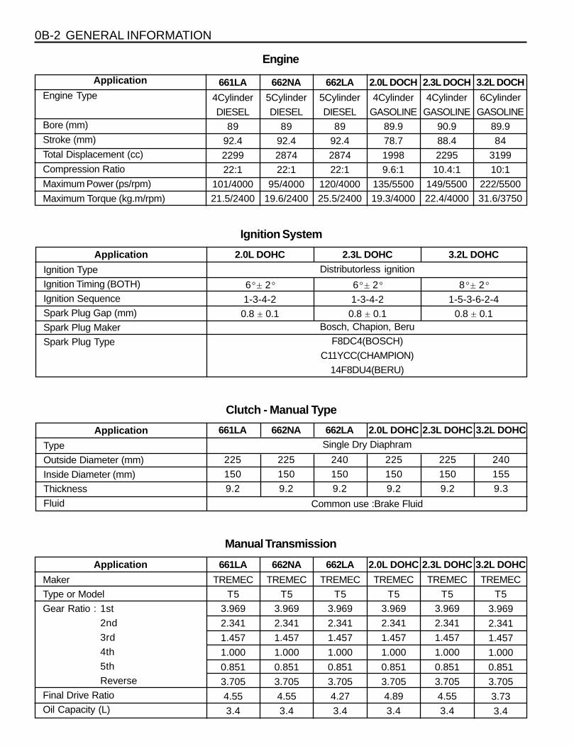
Ignition System
Clutch - Manual Type
2.0L DOHC
6° ± 2°
1-3-4-2
0.8 ± 0.1
2.3L DOHC
6° ± 2°
1-3-4-2
0.8 ± 0.1
3.2L DOHC
8° ± 2°
1-5-3-6-2-4
0.8 ± 0.1
Distributorless ignition
Bosch, Chapion, Beru
F8DC4(BOSCH)
C11YCC(CHAMPION)
14F8DU4(BERU)
661LA
225
150
9.2
662NA
225
150
9.2
662LA
240
150
9.2
2.0L DOHC
225
150
9.2
2.3L DOHC
225
150
9.2
3.2L DOHC
240
155
9.3
Application
Type
Outside Diameter (mm)
Inside Diameter (mm)
Thickness
Fluid
Single Dry Diaphram
Common use :Brake Fluid
Application
Maker
Type or Model
Gear Ratio : 1st
2nd
3rd
4th
5th
Reverse
Final Drive Ratio
Oil Capacity (L)
Manual Transmission
662NA
TREMEC
T5
3.969
2.341
1.457
1.000
0.851
3.705
4.55
3.4
662LA
TREMEC
T5
3.969
2.341
1.457
1.000
0.851
3.705
4.27
3.4
2.0L DOHC
TREMEC
T5
3.969
2.341
1.457
1.000
0.851
3.705
4.89
3.4
2.3L DOHC
TREMEC
T5
3.969
2.341
1.457
1.000
0.851
3.705
4.55
3.4
3.2L DOHC
TREMEC
T5
3.969
2.341
1.457
1.000
0.851
3.705
3.73
3.4
Engine
661LA
4Cylinder
DIESEL
89
92.4
2299
22:1
101/4000
21.5/2400
Application
Engine Type
Bore (mm)
Stroke (mm)
Total Displacement (cc)
Compression Ratio
Maximum Power (ps/rpm)
Maximum Torque (kg.m/rpm)
662NA
5Cylinder
DIESEL
89
92.4
2874
22:1
95/4000
19.6/2400
662LA
5Cylinder
DIESEL
89
92.4
2874
22:1
120/4000
25.5/2400
2.0L DOCH
4Cylinder
GASOLINE
89.9
78.7
1998
9.6:1
135/5500
19.3/4000
2.3L DOCH
4Cylinder
GASOLINE
90.9
88.4
2295
10.4:1
149/5500
22.4/4000
3.2L DOCH
6Cylinder
GASOLINE
89.9
84
3199
10:1
222/5500
31.6/3750
GENERAL INFORMATION 0B-3
661LA
BTRA
M74 4WD
2.741
1.508
1.000
0.708
2.429
5.38
9
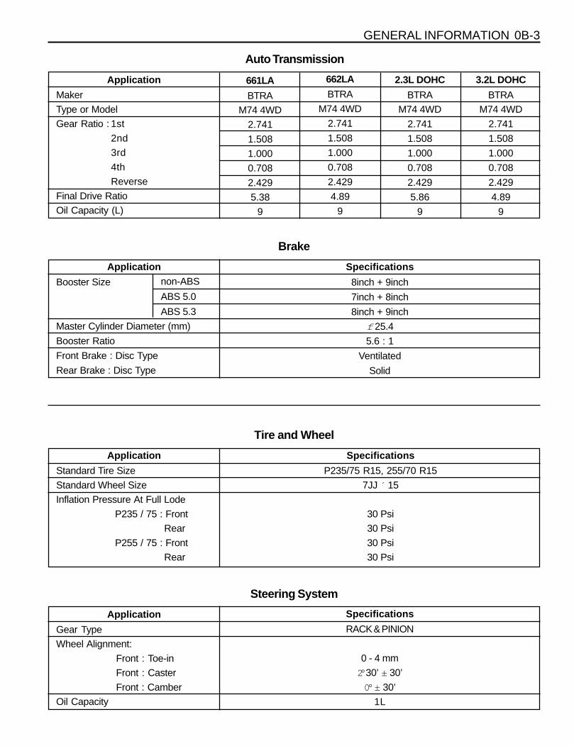
Auto Transmission
Application
Maker
Type or Model
Gear Ratio : 1st
2nd
3rd
4th
Reverse
Final Drive Ratio
Oil Capacity (L)
662LA
BTRA
M74 4WD
2.741
1.508
1.000
0.708
2.429
4.89
9
2.3L DOHC
BTRA
M74 4WD
2.741
1.508
1.000
0.708
2.429
5.86
9
3.2L DOHC
BTRA
M74 4WD
2.741
1.508
1.000
0.708
2.429
4.89
9
Specifications
RACK & PINION
0 - 4 mm
2° 30’ ± 30’
0° ± 30’
1L
Tire and Wheel
Specifications
P235/75 R15, 255/70 R15
7JJ ´ 15
30 Psi
30 Psi
30 Psi
30 Psi
Application
Standard Tire Size
Standard Wheel Size
Inflation Pressure At Full Lode
P235 / 75 : Front
Rear
P255 / 75 : Front
Rear
Application
Booster Size
Master Cylinder Diameter (mm)
Booster Ratio
Front Brake : Disc Type
Rear Brake : Disc Type
Specifications
8inch + 9inch
7inch + 8inch
8inch + 9inch
f 25.4
5.6 : 1
Ventilated
Solid
Brake
non-ABS
ABS 5.0
ABS 5.3
Application
Gear Type
Wheel Alignment:
Front : Toe-in
Front : Caster
Front : Camber
Oil Capacity
Steering System
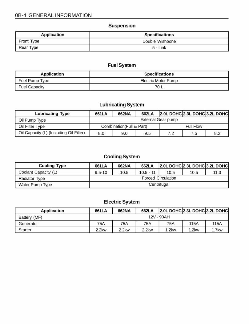
0B-4 GENERAL INFORMATION
Application
Front Type
Rear Type
Suspension
Specifications
Double Wishbone
5 - Link
Application
Fuel Pump Type
Fuel Capacity
Specifications
Electric Motor Pump
70 L
Fuel System
Lubricating Type
Oil Pump Type
Oil Filter Type
Oil Capacity (L) (Including Oil Filter)
Lubricating System
661LA
8.0
662NA
9.0
662LA
9.5
2.0L DOHC
7.2
2.3L DOHC
7.5
3.2L DOHC
8.2
External Gear pump
Combination(Full & Part) Full Flow
Cooling Type
Coolant Capacity (L)
Radiator Type
Water Pump Type
Cooling System
661LA
9.5-10
662NA
10.5
662LA
10.5 - 11
2.0L DOHC
10.5
2.3L DOHC
10.5
3.2L DOHC
11.3Forced Circulation
Centrifugal
Application
Battery (MF)
Generator
Starter
Electric System
661LA
75A
2.2kw
662NA
75A
2.2kw
662LA
75A
2.2kw
2.0L DOHC
75A
1.2kw
2.3L DOHC
115A
1.2kw
3.2L DOHC
115A
1.7kw
12V - 90AH
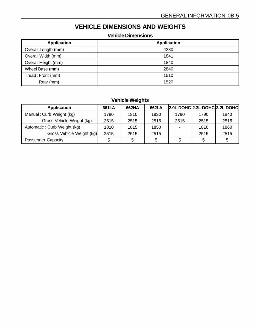
GENERAL INFORMATION 0B-5
Application
Overall Length (mm)
Overall Width (mm)
Overall Height (mm)
Wheel Base (mm)
Tread : Front (mm)
Rear (mm)
VEHICLE DIMENSIONS AND WEIGHTSVehicle Dimensions
Application
Manual : Curb Weight (kg)
Gross Vehicle Weight (kg)
Automatic : Curb Weight (kg)
Gross Vehicle Weight (kg)
Passenger Capacity
Vehicle Weights
Application
4330
1841
1840
2840
1510
1520
661LA
1790
2515
1810
2515
5
662NA
1810
2515
1815
2515
5
662LA
1830
2515
1850
2515
5
2.0L DOHC
1790
2515
-
-
5
2.3L DOHC
1790
2515
1810
2515
5
3.2L DOHC
1840
2515
1860
2515
5
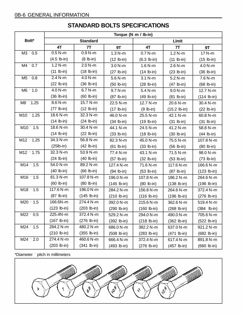
0B-6 GENERAL INFORMATION
STANDARD BOLTS SPECIFICATIONS
Bolt*Torque (N ·m / Ib-in)
Standard Limit4T 7T 9T 4T 7T 9T
M3 ´ 0.5
M4 ´ 0.7
M5 ´ 0.8
M6 ´ 1.0
M8 ´ 1.25
M10 ´ 1.25
M10 ´ 1.5
M12 ´ 1.25
M12 ´ 1.75
M14 ´ 1.5
M16 ´ 1.5
M18 ´ 1.5
M20 ´ 1.5
M22 ´ 0.5
M24 ´ 1.5
M24 ´ 2.0
0.5 N·····m
(4.5 lb-in)
1.2 N·····m
(11 lb-in)
2.4 N·····m
(22 lb-in)
4.0 N·····m
(36 lb-in)
8.6 N·····m
(77 lb-in)
18.6 N·····m
(14 lb-in)
18.6 N·····m
(14 lb-in)
34.3 N·····m
(25lb-in)
32.3 N·····m
(24 lb-in)
54.0 N·····m
(40 lb-in)
81.3 N·····m
(60 lb-in)
117.6 N·····m
(87 lb-in)
166.6N·····m
(123 lb-in)
225.4N·····m
(167 lb-in)
284.2 N·····m
(210 lb-in)
274.4 N·····m
(203 lb-in)
0.9 N·····m
(8 lb-in)
2.0 N·····m
(18 lb-in)
4.0 N·····m
(36 lb-in)
6.7 N·····m
(60 lb-in)
15.7 N·····m
(12 lb-in)
32.3 N·····m
(24 lb-in)
30.4 N·····m
(22 lb-in)
56.8 N·····m
(42 lb-in)
53.9 N·····m
(40 lb-in)
89.2 N·····m
(66 lb-in)
107.8 N·····m
(80 lb-in)
196.0 N·····m
(145 lb-in)
274.4 N·····m
(203 lb-in)
372.4 N·····m
(276 lb-in)
480.2 N·····m
(355 lb-in)
460.6 N·····m
(341 lb-in)
1.3 N·····m
(12 lb-in)
3.0 N·····m
(27 lb-in)
5.6 N·····m
(50 lb-in)
9.7 N·····m
(87 lb-in)
22.5 N·····m
(17 lb-in)
46.0 N·····m
(34 lb-in)
44.1 N·····m
(33 lb-in)
82.3 N·····m
(61 lb-in)
77.4 N·····m
(57 lb-in)
127.4 N·····m
(94 lb-in)
196.0 N·····m
(145 lb-in)
284.2 N·····m
(210 lb-in)
392.0 N·····m
(290 lb-in)
529.2 N·····m
(392 lb-in)
686.0 N·····m
(508 lb-in)
666.4 N·····m
(493 lb-in)
0.7 N·····m
(6.3 lb-in)
1.6 N·····m
(14 lb-in)
3.1 N·····m
(28 lb-in)
5.4 N·····m
(49 lb-in)
12.7 N·····m
(9 lb-in)
25.5 N·····m
(19 lb-in)
24.5 N·····m
(18 lb-in)
45.0 N·····m
(33 lb-in)
43.1 N·····m
(32 lb-in)
71.6 N·····m
(53 lb-in)
107.8 N·····m
(80 lb-in)
156.8 N·····m
(116 lb-in)
215.6 N·····m
(160 lb-in)
294.0 N·····m
(218 lb-in)
382.2 N·····m
(283 lb-in)
372.4 N·····m
(276 lb-in)
1.2 N·····m
(11 lb-in)
2.6 N·····m
(23 lb-in)
5.2 N·····m
(47 lb-in)
9.0 N·····m
(81 lb-in)
20.6 N·····m
(15.2 lb-in)
42.1 N·····m
(31 lb-in)
41.2 N·····m
(30 lb-in)
75.5 N·····m
(56 lb-in)
71.5 N·····m
(53 lb-in)
117.6 N·····m
(87 lb-in)
186.2 N·····m
(138 lb-in)
264.6 N·····m
(196 lb-in)
362.6 N·····m
(268 lb-in)
490.0 N·····m
(362 lb-in)
637.0 N·····m
(471 lb-in)
617.4 N·····m
(457 lb-in)
17 N·····m
(15 lb-in)
4.0 N·····m
(36 lb-in)
7.6 N·····m
(68 lb-in)
12.7 N·····m
(114 lb-in)
30.4 N·····m
(22 lb-in)
60.8 N·····m
(31 lb-in)
58.8 N·····m
(44 lb-in)
107.8 N·····m
(80 lb-in)
98.0 N·····m
(73 lb-in)
166.6 N·····m
(123 lb-in)
264.6 N·····m
(196 lb-in)
372.4 N·····m
(276 lb-in)
519.4 N·····m
(384 lb-in)
705.6 N·····m
(522 lb-in)
921.2 N·····m
(682 lb-in)
891.8 N·····m
(660 lb-in)
*Diameter ́ pitch in millimeters
GENERAL INFORMATION 0B-7
MAINTENANCE AND REPAIR
MAINTENANCE AND LUBRICATION
Fuel Filter ReplacementReplace the engine fuel filter every.
l Gasoline Engine : 60,000km (36,000 miles)
l Diesel Engine : 45,000km (24,000 miles)
Spark Plug ReplacementReplace spark plugs with same type.
l Type : BOSCH : F8DC4
BERU : 14F-8DU4
Champion : C11YCC
l Gap : 0.8 ± 0.1 mm
Spark Plug Wire ReplacementClean wires and inspect them for burns, cracks or otherdamage. Check the wire boot fit at the Distributor and atthe spark plugs. Replace the wires as needed.
Brake System ServiceCheck the disc brake pads or the drum brake linings.Check the pad and the lining thickness carefully.
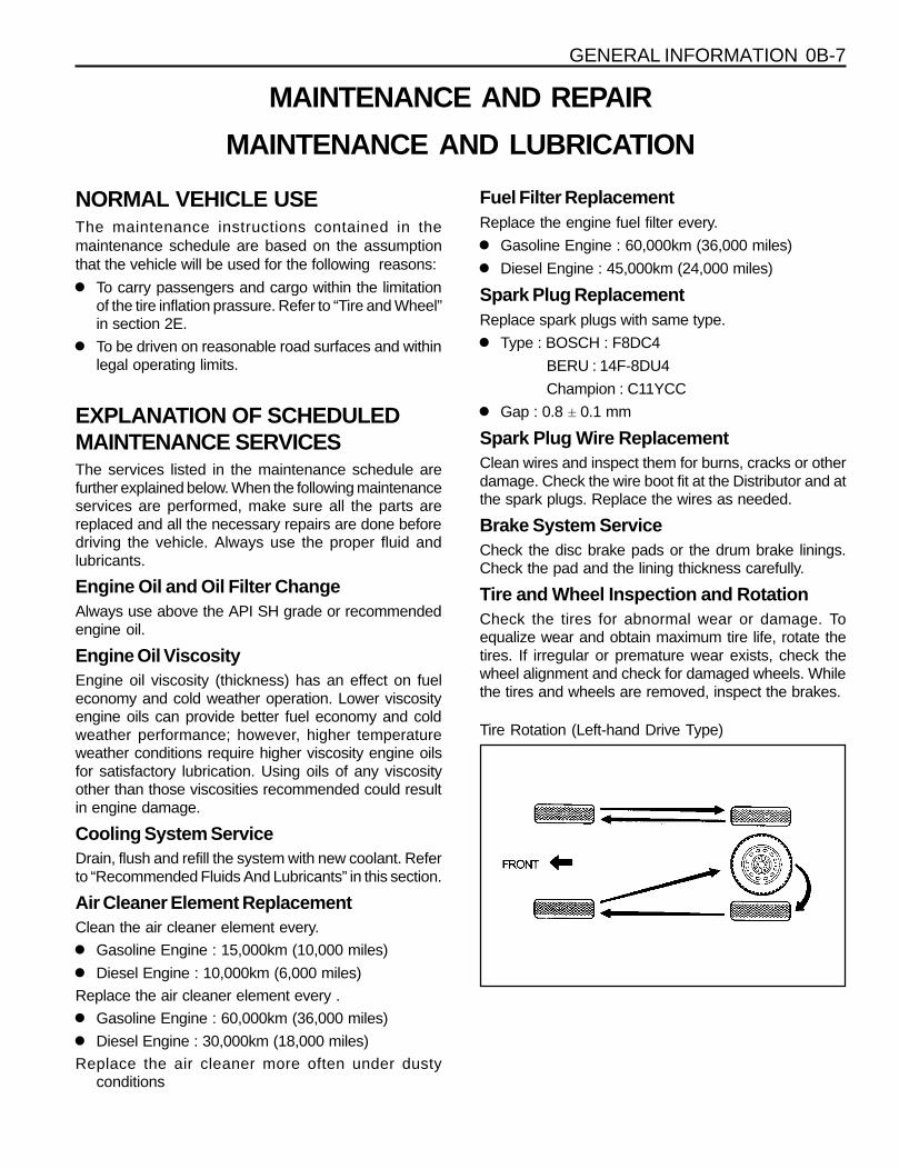
Tire and Wheel Inspection and RotationCheck the tires for abnormal wear or damage. Toequalize wear and obtain maximum tire life, rotate thetires. If irregular or premature wear exists, check thewheel alignment and check for damaged wheels. Whilethe tires and wheels are removed, inspect the brakes.
NORMAL VEHICLE USEThe maintenance instructions contained in themaintenance schedule are based on the assumptionthat the vehicle will be used for the following reasons:
l To carry passengers and cargo within the limitationof the tire inflation prassure. Refer to “Tire and Wheel”in section 2E.
l To be driven on reasonable road surfaces and withinlegal operating limits.
EXPLANATION OF SCHEDULEDMAINTENANCE SERVICESThe services listed in the maintenance schedule arefurther explained below. When the following maintenanceservices are performed, make sure all the parts arereplaced and all the necessary repairs are done beforedriving the vehicle. Always use the proper fluid andlubricants.
Engine Oil and Oil Filter ChangeAlways use above the API SH grade or recommendedengine oil.
Engine Oil ViscosityEngine oil viscosity (thickness) has an effect on fueleconomy and cold weather operation. Lower viscosityengine oils can provide better fuel economy and coldweather performance; however, higher temperatureweather conditions require higher viscosity engine oilsfor satisfactory lubrication. Using oils of any viscosityother than those viscosities recommended could resultin engine damage.
Cooling System ServiceDrain, flush and refill the system with new coolant. Referto “Recommended Fluids And Lubricants” in this section.
Air Cleaner Element ReplacementClean the air cleaner element every.
l Gasoline Engine : 15,000km (10,000 miles)
l Diesel Engine : 10,000km (6,000 miles)
Replace the air cleaner element every .
l Gasoline Engine : 60,000km (36,000 miles)
l Diesel Engine : 30,000km (18,000 miles)
Replace the air cleaner more often under dustyconditions
Tire Rotation (Left-hand Drive Type)
0B-8 GENERAL INFORMATION
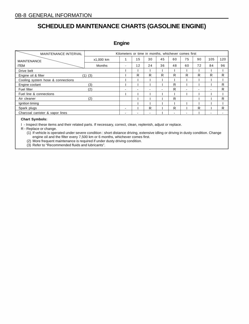
SCHEDULED MAINTENANCE CHARTS (GASOLINE ENGINE)
Engine
MonthsMAINTENANCEITEM
MAINTENANCE INTERVAL Kilometers or time in months, whichever comes first
1201059075604530151
9684726048362412-
x1,000 km
Chart Symbols:
I - Inspect these items and their related parts. If necessary, correct, clean, replenish, adjust or replace.R - Replace or change.
(1) If vehicle is operated under severe condition : short distance driving, extensive idling or driving in dusty condition. Changeengine oil and the filter every 7,500 km or 6 months, whichever comes first.
(2) More frequent maintenance is required if under dusty driving condition.(3) Refer to “Recommended fluids and lubricants”.
Drive beltEngine oil & filter (1) (3)Cooling system hose & connectionsEngine coolant (3)Fuel filter (2)Fuel line & connectionsAir cleaner (2)
Ignition timingSpark plugs
Charcoal canister & vapor lines
IIII-I
--
IRII-IIII-
IRII-IIIR-
IRII-IIIII
IRIRRIRIR-
IRII-I
II-
IRII-IIIRI
IRII-IIII-
IRIRRIRIR-
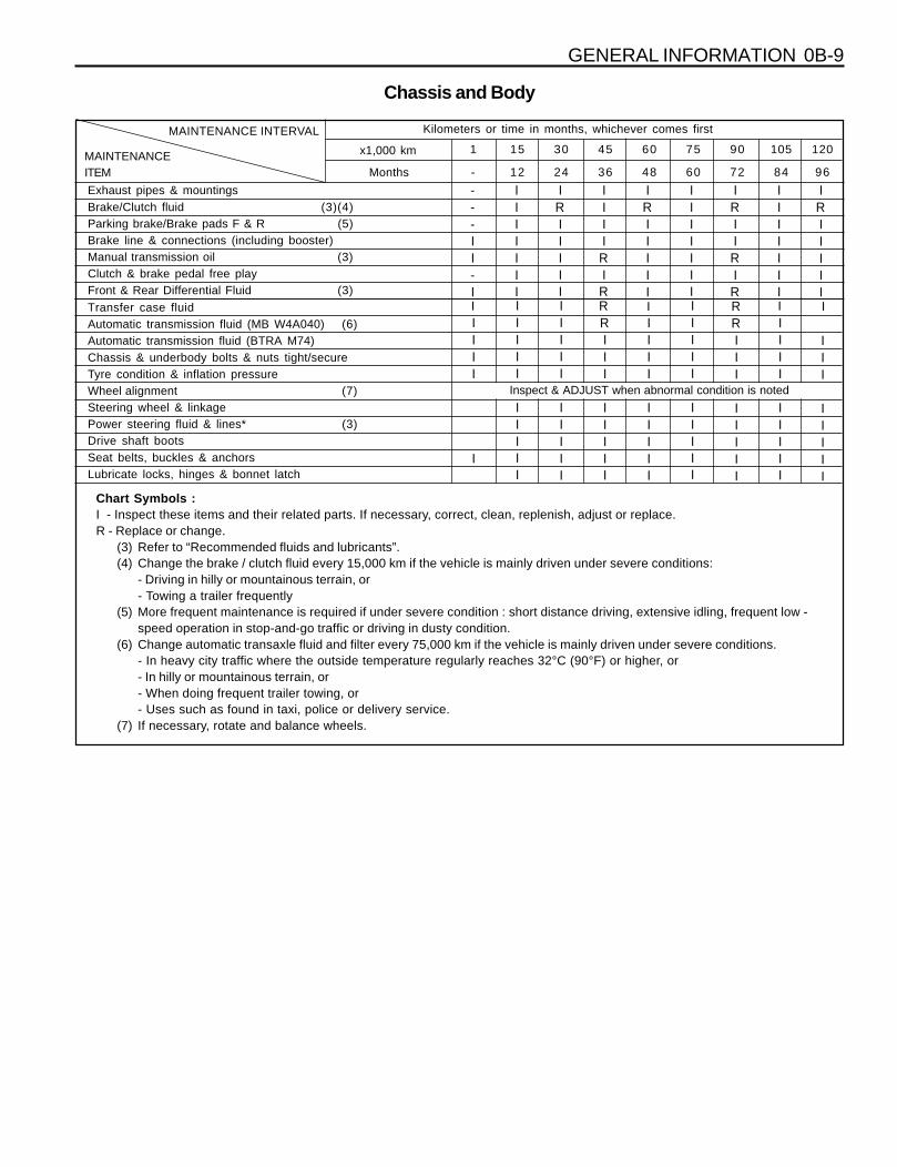
GENERAL INFORMATION 0B-9
Chassis and Body
MonthsMAINTENANCEITEM
MAINTENANCE INTERVAL Kilometers or time in months, whichever comes first
1201059075604530151
9684726048362412-
x1,000 km
Exhaust pipes & mountingsBrake/Clutch fluid (3)(4)Parking brake/Brake pads F & R (5)Brake line & connections (including booster)Manual transmission oil (3)Clutch & brake pedal free playFront & Rear Differential Fluid (3)
IRIIIII
---II-I
IIIIIII
IRIIIII
IIIIRIR
IIIIIII
IRIIRIR
IIIIIII
IRIIIII
Automatic transmission fluid (MB W4A040) (6)Automatic transmission fluid (BTRA M74)Chassis & underbody bolts & nuts tight/secureTyre condition & inflation pressureWheel alignment (7)Steering wheel & linkagePower steering fluid & lines* (3)Drive shaft bootsSeat belts, buckles & anchorsLubricate locks, hinges & bonnet latch
IIII
I
IIIII
IIIII
IIIII
IIIII
RIII
IIIII
IIII
IIIII
IIIII
IIIII
RRIII
IIIII
IIII
IIIII
Transfer case fluid R II I
Inspect & ADJUST when abnormal condition is noted
I
III
IIIII
Chart Symbols :I - Inspect these items and their related parts. If necessary, correct, clean, replenish, adjust or replace.R - Replace or change.
(3) Refer to “Recommended fluids and lubricants”.(4) Change the brake / clutch fluid every 15,000 km if the vehicle is mainly driven under severe conditions:
- Driving in hilly or mountainous terrain, or- Towing a trailer frequently
(5) More frequent maintenance is required if under severe condition : short distance driving, extensive idling, frequent low -speed operation in stop-and-go traffic or driving in dusty condition.
(6) Change automatic transaxle fluid and filter every 75,000 km if the vehicle is mainly driven under severe conditions.- In heavy city traffic where the outside temperature regularly reaches 32°C (90°F) or higher, or- In hilly or mountainous terrain, or- When doing frequent trailer towing, or- Uses such as found in taxi, police or delivery service.
(7) If necessary, rotate and balance wheels.
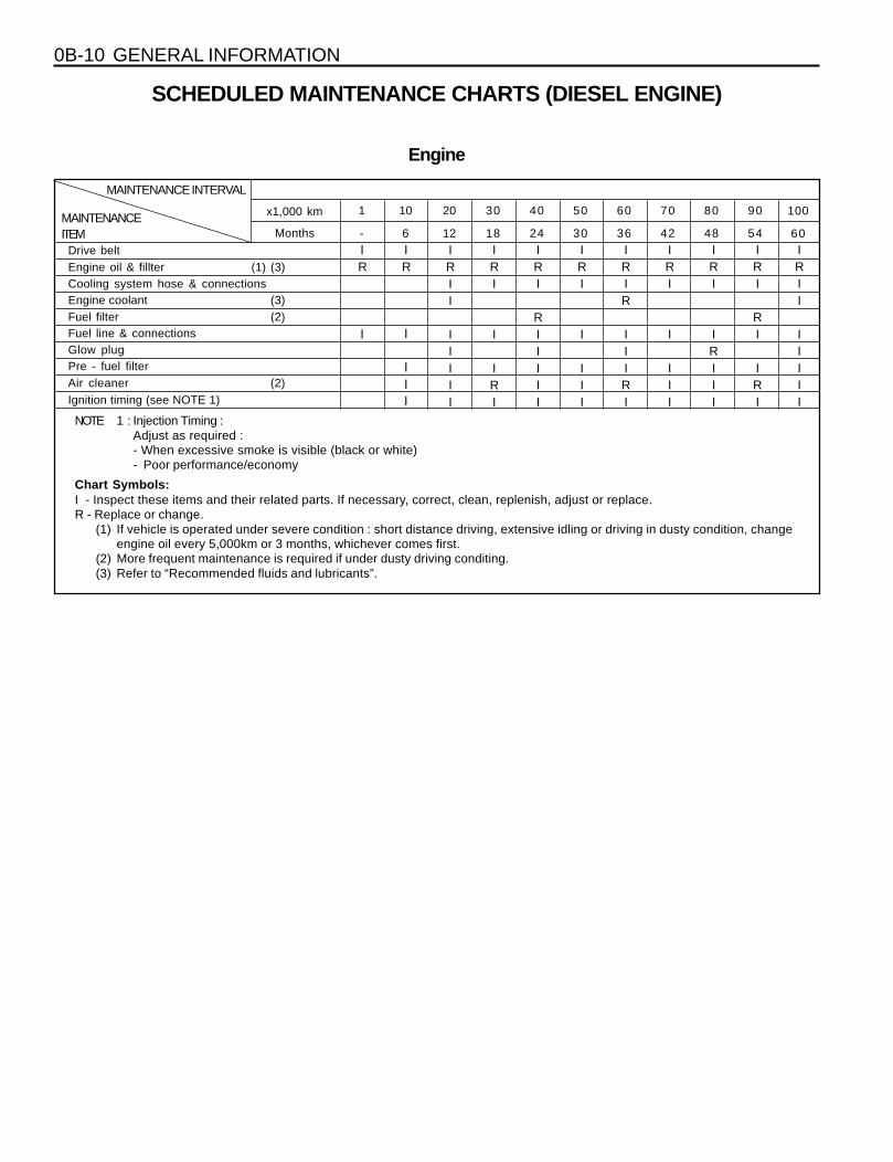
0B-10 GENERAL INFORMATION
SCHEDULED MAINTENANCE CHARTS (DIESEL ENGINE)
Engine
Months -MAINTENANCEITEM
MAINTENANCE INTERVAL
1009080706050403020101
6054484236302418126
x1,000 km
NOTE 1 : Injection Timing :Adjust as required :- When excessive smoke is visible (black or white)- Poor performance/economy
Chart Symbols:I - Inspect these items and their related parts. If necessary, correct, clean, replenish, adjust or replace.R - Replace or change.
(1) If vehicle is operated under severe condition : short distance driving, extensive idling or driving in dusty condition, changeengine oil every 5,000km or 3 months, whichever comes first.
(2) More frequent maintenance is required if under dusty driving conditing.(3) Refer to “Recommended fluids and lubricants”.
Drive beltEngine oil & fillter (1) (3)Cooling system hose & connectionsEngine coolant (3)Fuel filter (2)Fuel line & connectionsGlow plugPre - fuel filterAir cleaner (2)Ignition timing (see NOTE 1)
IR
I
IR
I
III
IRII
IIIII
IRI
I
IRI
IRI
RIIIII
IRI
I
III
IRIR
IIIRI
IRI
I
III
IRI
IRIII
IRI
RI
IRI
IRII
IIIII

GENERAL INFORMATION 0B-11
Chassis and Body
Months -MAINTENANCEITEM
MAINTENANCE INTERVAL Kilometers or time in months, whichever comes first
1009080706050403020101
6054484236302418126
x1,000 km
Exhaust pipes & mountingsBrake/clutch fluid (3) (4)Parking brake/Brake pads (F & R) (5)Brake line & connections (including booster)Manual transmission fluid (3)Clutch & brake pedal free playF & R Differential fluid (3)
I
I
IIIIIII
IIIIIII
IRIIIII
IIIIIII
IIIIRIR
IRIIIII
IIIIIII
IIIIIII
IRIIIII
IIIIRIR
Automatic transmission fluid (BTRA M74) (6)Chassis & underbody bolts & nuts tight/secureTyre condition & inflation pressureWheel alignment (7)Steering wheel & linkagePower steering fluid & lines* (3)Drive shaft bootsSeat belts, buckles & anchorsLubricate locks, hinges & bonnet latch
III
IIIII
III
IIIII
IIII
IIIII
III
IIIII
III
IIIII
III
IIIII
III
I
III
III
IIIII
III
IIIII
Transfer case fluid (3) R I R
I
I I
II
III
IIII
IIIII
Inspect & ADJUST when abnormal condition is noted
I I I
Chart Symbols :I - Inspect these items and their related parts. If necessary, correct, clean, replenish, adjust or replace.R - Replace or change.
(3) Refer to “Recommended fluids and lubricants”.(4) Change the brake / clutch fluid more regularly if the vehicle is mainly driven under severe conditions :
- Driving in hilly or mountainous terrain, or- Towing a trailer frequently
(5) More frequent maintenance is required if under severe condition : short distance driving, extensive idling, frequent low -speed operation in stop-and-go traffic or driving in dusty condition.
(6) Change automatic transmission fluid every 70,000 km if the vehicle is mainly driven under severe conditions.- In heavy city traffic where the outside temperature regularly reaches 32°C (90°F) or higher, or- In hilly or mountainous terrain, or- When doing frequent trailer towing, or- Uses such as found in taxi, police or delivery service.
(7) If necessary, rotate and balance wheels.
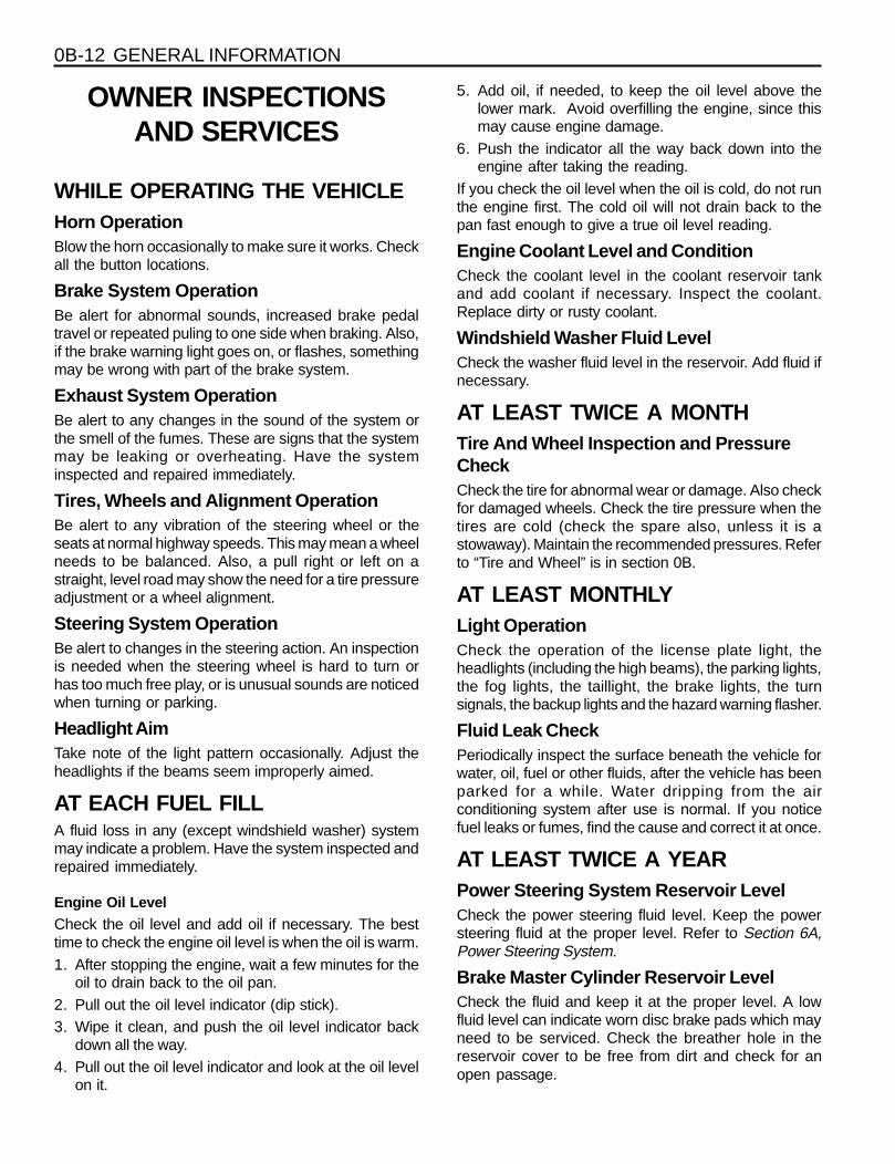
0B-12 GENERAL INFORMATION
OWNER INSPECTIONSAND SERVICES
WHILE OPERATING THE VEHICLEHorn OperationBlow the horn occasionally to make sure it works. Checkall the button locations.
Brake System OperationBe alert for abnormal sounds, increased brake pedaltravel or repeated puling to one side when braking. Also,if the brake warning light goes on, or flashes, somethingmay be wrong with part of the brake system.
Exhaust System OperationBe alert to any changes in the sound of the system orthe smell of the fumes. These are signs that the systemmay be leaking or overheating. Have the systeminspected and repaired immediately.
Tires, Wheels and Alignment OperationBe alert to any vibration of the steering wheel or theseats at normal highway speeds. This may mean a wheelneeds to be balanced. Also, a pull right or left on astraight, level road may show the need for a tire pressureadjustment or a wheel alignment.
Steering System OperationBe alert to changes in the steering action. An inspectionis needed when the steering wheel is hard to turn orhas too much free play, or is unusual sounds are noticedwhen turning or parking.
Headlight AimTake note of the light pattern occasionally. Adjust theheadlights if the beams seem improperly aimed.
AT EACH FUEL FILLA fluid loss in any (except windshield washer) systemmay indicate a problem. Have the system inspected andrepaired immediately.
Engine Oil Level
Check the oil level and add oil if necessary. The besttime to check the engine oil level is when the oil is warm.1. After stopping the engine, wait a few minutes for the
oil to drain back to the oil pan.2. Pull out the oil level indicator (dip stick).3. Wipe it clean, and push the oil level indicator back
down all the way.4. Pull out the oil level indicator and look at the oil level
on it.
5. Add oil, if needed, to keep the oil level above thelower mark. Avoid overfilling the engine, since thismay cause engine damage.
6. Push the indicator all the way back down into theengine after taking the reading.
If you check the oil level when the oil is cold, do not runthe engine first. The cold oil will not drain back to thepan fast enough to give a true oil level reading.
Engine Coolant Level and ConditionCheck the coolant level in the coolant reservoir tankand add coolant if necessary. Inspect the coolant.Replace dirty or rusty coolant.
Windshield Washer Fluid LevelCheck the washer fluid level in the reservoir. Add fluid ifnecessary.
AT LEAST TWICE A MONTHTire And Wheel Inspection and PressureCheckCheck the tire for abnormal wear or damage. Also checkfor damaged wheels. Check the tire pressure when thetires are cold (check the spare also, unless it is astowaway). Maintain the recommended pressures. Referto “Tire and Wheel” is in section 0B.
AT LEAST MONTHLYLight OperationCheck the operation of the license plate light, theheadlights (including the high beams), the parking lights,the fog lights, the taillight, the brake lights, the turnsignals, the backup lights and the hazard warning flasher.
Fluid Leak CheckPeriodically inspect the surface beneath the vehicle forwater, oil, fuel or other fluids, after the vehicle has beenparked for a while. Water dripping from the airconditioning system after use is normal. If you noticefuel leaks or fumes, find the cause and correct it at once.
AT LEAST TWICE A YEARPower Steering System Reservoir LevelCheck the power steering fluid level. Keep the powersteering fluid at the proper level. Refer to Section 6A,Power Steering System.
Brake Master Cylinder Reservoir LevelCheck the fluid and keep it at the proper level. A lowfluid level can indicate worn disc brake pads which mayneed to be serviced. Check the breather hole in thereservoir cover to be free from dirt and check for anopen passage.
GENERAL INFORMATION 0B-13
Weather-Strip LubricationApply a thin film silicone grease using a clean cloth.
EACH TIME THE OIL IS CHANGEDBrake System InspectionThis inspection should be done when the wheels areremoved for rotation. Inspect the lines and the hosesfor proper hookup, binding, leaks, cracks, chafing, etc.Inspect the disc brake pads for wear. Inspect the rotorsfor surface condition. Inspect other brake parts, theparking brake, etc., at the same time. Inspect the brakesmore often if habit or conditions result in frequent braking.
Steering, Suspension and Front Drive AxleBoot And Seal InspectionInspect the front and rear suspension and the steeringsystem for damaged, loose or missing parts, signs ofwear or lack of lubrication. Inspect the power steeringline and the hoses for proper hookup, binding, leaks,cracks, chafing, etc. Clean and inspect the drive axleboot and seals for damage, tears or leakage. Replacethe seals if necessary.
Exhaust System InspectionInspect the complete system (including the catalyticconverter if equipped). Inspect the body near the exhaustsystem. Look for broken, damaged, missing, or out-of-position parts as well as open seams, holes, looseconnections, or other conditions which could cause heatbuildup in the floor pan or could let exhaust fumes seepinto the trunk or passenger compartment.
Throttle Linkage InspectionInspect the throttle linkage for interference or binding,damaged, or missing parts. Lubricate all linkage jointsand throttle cable joints, the intermediate throttle shaftbearing, the return spring at throttle valve assembly, andthe accelerator pedal sliding face with suitable grease.Check the throttle cable for free movements.
Engine Drive BeltsInspect all belts for cracks, fraying, wear and propertension. Adjust or replace the belts as needed.
Hood Latch OperationWhen opening the hood, note the operation of thesecondary latch. It should keep the hood from openingall the way when the primary latch is released. The hoodmust close firmly.
AT LEAST ANNUALLYLap and Shoulder Belts Condition andOperationInspect the belt system including: the webbing, thebuckles, the latch plates, the retractor, the guide loopsand the anchors.
Movable Head Restraint OperationOn vehicles with movable head restraints, the restraintsmust stay in the desired position.
Spare Tire and Jack StorageBe alert to rattles in the rear of the vehicle. The sparetire, all the jacking equipment, and the tools must besecurely stowed at all times. Oil the jack ratchet or thescrew mechanism after each use.
Key Lock ServiceLubricate the key lock cylinder.
Body Lubrication ServiceLubricate all the body door hinges including the hood,the fuel door, the rear compartment hinges and thelatches, the glove box and the console doors, and anyfolding seat hardware.
Underbody FlushingFlushing the underbody will remove any corrosivematerials used for ice and snow removal and dust control.At least every spring clean the underbody. First, loosenthe sediment packed in closed areas of the vehicle. Thenflush the underbody with plain water.
Engine Cooling SystemInspect the coolant and freeze protection fluid. If the fluidis dirty or rusty, drain, flush and refill the engine coolingsystem with new coolant. Keep the coolant at the propermixture in order to ensure proper freeze protection,corrosion protection and engine operating temperature.Inspect the hoses. Replace the cracked, swollen, ordeteriorated hoses. Tighten the clamps. Clean theoutside of the radiator and the air conditioningcondenser. Wash the filler cap and the neck. Pressuretest the cooling system and the cap in order to helpensure proper operation.

0B-14 GENERAL INFORMATION
Usage
Engine Oil
(Change with filter)
Engine Coolant
Brake / Clutch Fluid
Power Steering System
Parking Brake Cable
Hood Latch Assembly
Hood and Door Hinges
Fuel Door Hinge
Rear Compartment Lid Hinges
Weatherstrips
RECOMMENDED FLUIDS AND LUBRICANTS
Capacity
8.2 L
7.5 L
9.5 L
8.0 L
11.3 L
10.5 L
10.5 - 11.0 L
9.5 - 10.0 L
Approx. 0.5L level must
be maintained between
MAX & MIN level
1.0 L
As required
As required
As required
As required
Fluid/Lubricant
Quality class - API ; SH grade or above
ACEA ; A2 or A3
MB sheet ; 229.1
Viscosity - MB sheet ; 224.1
Quality class - API ; CG grade or above
ACEA ; B2 or B3
MB sheet ; 228.1, 228.3,
228.5, 229.1
Viscosity - MB sheet ; 224.1
ALUTEC P-78
DOT-3 & SAE J 1703
ATF DEXRON-II
Grease
Grease
Spray type grease
Silicone grease
3.2L DOHC
2.3L DOHC
662LA
661LA
3.2L DOHC2.3L DOHC662LA661LA

GENERAL INFORMATION 0B-15
GENERAL DESCRIPTIONAND SYSTEM OPERATION
GENERAL REPAIR INSTRUCTIONSl If a floor jack is used, the following precautions are
recommended.l Park the vehicle on level ground, “block” the front or
rear wheels, set the jack against the frame, raise thevehicle and support it with chassis stands and thenperform the service operation.
l Before performing the service operation, disconnectthe negative battery cable in order to reduce thechance of cable damaged and burning due to short-cir cuiting.
l Use a cover on the body, the seats and the floor toprotect them against damage and contamination.
l Handle brake fluid and antifreeze solution with careas they can cause paint damage.
l The use of proper tools, and the recommendedessential and available tools where specified, areimportant for efficient and reliable performance ofthe service repairs.
l Use genuine DAEWOO parts.l Discard used cotter pins, gaskets, O-rings, oil seals,
lock washers and self-locking nuts. Prepare new onesfor installation. Normal function of these parts cannotbe maintained if these parts are reused.
l Keep the disassembled parts neatly in groups tofacilitate proper and smooth reassembly.
l Keep attaching bolts and nuts separated, as theyvary in hardness and design depending on theposition of the installation.
l Clean the parts before inspection or reassembly.l Also clean the oil parts, etc. Use compressed air to
make certain they are free of restrictions.l Lubricate rotating and sliding faces of parts with oil
or grease before installation.l When necessary, use a sealer on gaskets to prevent
leakage.l Carefully observe all specifications for bolt and nut
torques.l When service operation is completed, make a final
check to be sure service was done properly and theproblem was corrected.
0B-16 GENERAL INFORMATION
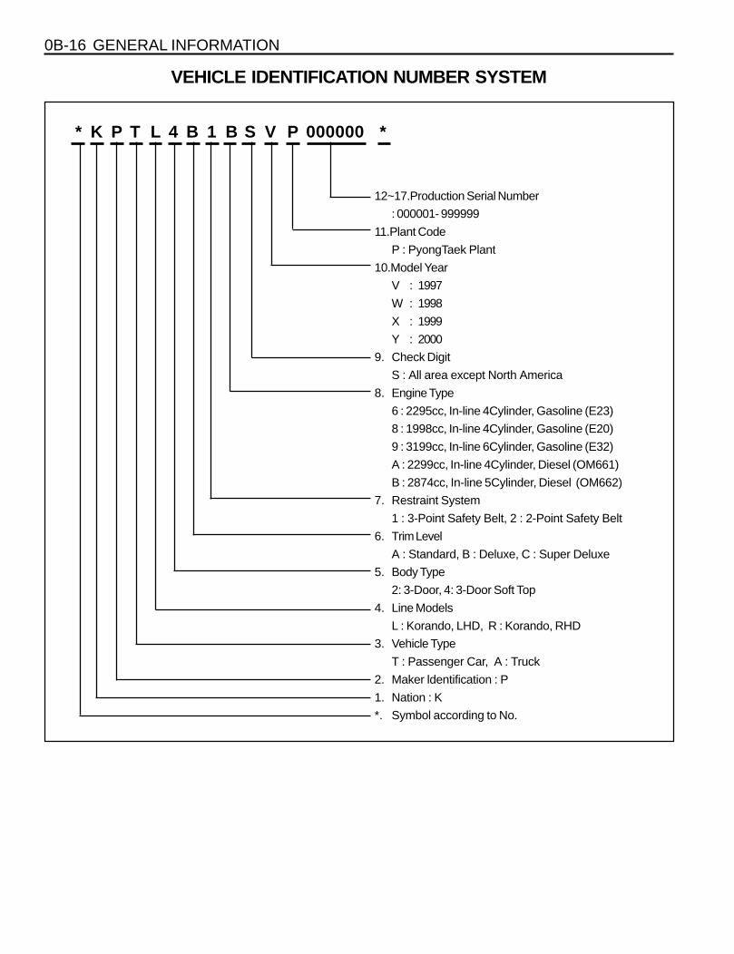
VEHICLE IDENTIFICATION NUMBER SYSTEM
* K P T L 4 B 1 B S V P 000000 *
12~17.Production Serial Number
: 000001- 999999
11.Plant Code
P : PyongTaek Plant
10.Model Year
V : 1997
W : 1998
X : 1999
Y : 2000
9. Check Digit
S : All area except North America
8. Engine Type
6 : 2295cc, In-line 4Cylinder, Gasoline (E23)
8 : 1998cc, In-line 4Cylinder, Gasoline (E20)
9 : 3199cc, In-line 6Cylinder, Gasoline (E32)
A : 2299cc, In-line 4Cylinder, Diesel (OM661)
B : 2874cc, In-line 5Cylinder, Diesel (OM662)
7. Restraint System
1 : 3-Point Safety Belt, 2 : 2-Point Safety Belt
6. Trim Level
A : Standard, B : Deluxe, C : Super Deluxe
5. Body Type
2: 3-Door, 4: 3-Door Soft Top
4. Line Models
L : Korando, LHD, R : Korando, RHD
3. Vehicle Type
T : Passenger Car, A : Truck
2. Maker ldentification : P
1. Nation : K
*. Symbol according to No.
GENERAL INFORMATION 0B-17
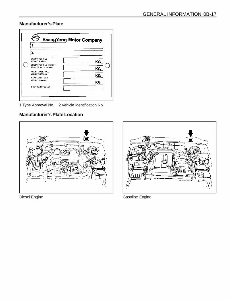
Manufacturer’s Plate
Manufacturer’s Plate Location
1.Type Approval No. 2.Vehicle Identification No.
Diesel Engine Gasoline Engine
0B-18 GENERAL INFORMATION
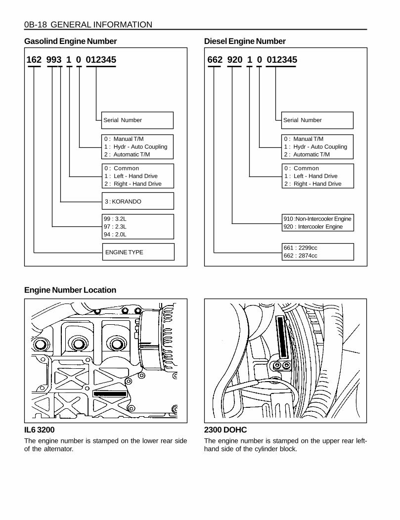
Engine Number Location
Gasolind Engine Number
162 993 1 0 012345
Serial Number
0 : Manual T/M1 : Hydr - Auto Coupling2 : Automatic T/M
99 : 3.2L97 : 2.3L94 : 2.0L
0 : Common1 : Left - Hand Drive2 : Right - Hand Drive
ENGINE TYPE
3 : KORANDO
2300 DOHCThe engine number is stamped on the upper rear left-hand side of the cylinder block.
IL6 3200The engine number is stamped on the lower rear sideof the alternator.
Diesel Engine Number
662 920 1 0 012345
Serial Number
0 : Manual T/M1 : Hydr - Auto Coupling2 : Automatic T/M
910 :Non-Intercooler Engine920 : Intercooler Engine
0 : Common1 : Left - Hand Drive2 : Right - Hand Drive
661 : 2299cc662 : 2874cc
GENERAL INFORMATION 0B-19
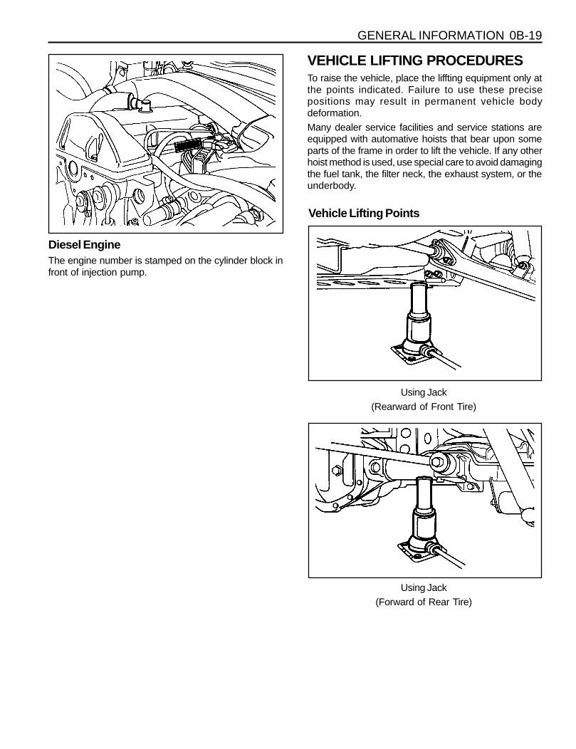
VEHICLE LIFTING PROCEDURESTo raise the vehicle, place the liffting equipment only atthe points indicated. Failure to use these precisepositions may result in permanent vehicle bodydeformation.Many dealer service facilities and service stations areequipped with automative hoists that bear upon someparts of the frame in order to lift the vehicle. If any otherhoist method is used, use special care to avoid damagingthe fuel tank, the filter neck, the exhaust system, or theunderbody.
Diesel EngineThe engine number is stamped on the cylinder block infront of injection pump.
Vehicle Lifting Points
Using Jack(Rearward of Front Tire)
Using Jack(Forward of Rear Tire)
SECTION 1
ENGINE
SECTION 1A1(M162 ENGINE)
GENERAL ENGINE INFORMATIONTABLE OF CONTENTS
Specifications. . . . . . . . . . . . . . . . . . . . . . . 1A1-1Engine Specifications . . . . . . . . . . . . . . . . . . 1A1-1
Component Locator . . . . . . . . . . . . . . . . . . 1A1-3Front View . . . . . . . . . . . . . . . . . . . . . . . . . . 1A1-3Side View . . . . . . . . . . . . . . . . . . . . . . . . . . . 1A1-4
Performance Curve . . . . . . . . . . . . . . . . . . 1A1-5E32 Engine . . . . . . . . . . . . . . . . . . . . . . . . . . 1A1-5
Special Tools . . . . . . . . . . . . . . . . . . . . . . . 1A1-6Special Tools Table . . . . . . . . . . . . . . . . . . . . 1A1-6
Diagnosis . . . . . . . . . . . . . . . . . . . . . . . . . . 1A1-7Oil Leak Diagnosis . . . . . . . . . . . . . . . . . . . . 1A1-7Engine Cranking at The
Front of Crankshaft . . . . . . . . . . . . . . . . . . 1A1-8Compression Pressure Test . . . . . . . . . . . . . 1A1-9Cylinder Pressure Leakage Test. . . . . . . . . 1A1-11
General Information . . . . . . . . . . . . . . . . . 1A1-13Cleanliness and Care . . . . . . . . . . . . . . . . . 1A1-13On-Engine Service . . . . . . . . . . . . . . . . . . . 1A1-13
Application
Engine Model
Displacement (CC)
Cylinder (Bore x Stroke) (mm)
Fuel Injection / Ignition System
Compression Ratio
Number of Cylinders
Camshaft Valve Arrangement
Camshaft Drive Type
Max. Output (ps/rpm)
Max. Torque (kg•m/rpm)
Firing Order
Ignition Type
Ignition Timing
Valve Timing Intake Open/Close
Exhaust Open/Close
Valve Clearance Adjustment
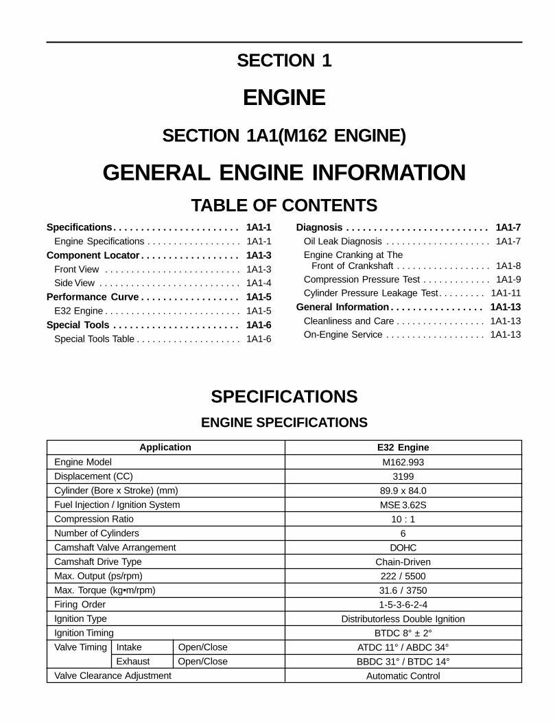
SPECIFICATIONSENGINE SPECIFICATIONS
E32 Engine
M162.993
3199
89.9 x 84.0
MSE 3.62S
10 : 1
6
DOHC
Chain-Driven
222 / 5500
31.6 / 3750
1-5-3-6-2-4
Distributorless Double Ignition
BTDC 8° ± 2°
ATDC 11° / ABDC 34°
BBDC 31° / BTDC 14°
Automatic Control

1A1-2 GENERAL ENGINE INFORMATION
Application
Idle Speed (rpm)
Fuel Injection Pressure (kg/cm²)
Oil Capacity (liter)
Lubrication Type
Oil Filter Type
Fuel
ENGINE SPECIFICATIONS (Cont'd)
E32 Engine
700 ± 50
3 - 4
8.2
Forced by Gear Pump
Full Flow with Paper Filter
Unleaded Gasoline
MSE 3.62S/3.53S (Motor steuer Elektronik : German)MSE : Engine Control Electronic
3.62S : 6 Cylinder Version
3.53S : 4 Cylinder Version


![Ssangyong Korando [4x2] (2010- ) Ssangyong Korando [4x4] … · 2018-11-23 · Ssangyong Korando [4x4] (2010- ) NO ORIGINAL. GB FR NL DE IT Enganches y Remolques Aragón SL no se](https://img.pdfslide.net/doc/110x75/5f2a97a5f43d864c1f30c1cf/ssangyong-korando-4x2-2010-ssangyong-korando-4x4-2018-11-23-ssangyong.jpg)