Embed Size (px)
DESCRIPTION
Krc4 Profinet 20 v3 En
Citation preview

Controller Option
KR C4 PROFINET 2.0
For KUKA System Software 8.2
For VW System Software 8.2
KUKA Roboter GmbH
Issued: 07.03.2011
Version: KR C4 PROFINET 2.0 V3 en

KR C4 PROFINET 2.0
2 / 57 Issued: 07.03.2011 Version: KR C4 PROFINET 2.0 V3 en
© Copyright 2011
KUKA Roboter GmbH
Zugspitzstraße 140
D-86165 Augsburg
Germany
This documentation or excerpts therefrom may not be reproduced or disclosed to third parties without the express permission of KUKA Roboter GmbH.
Other functions not described in this documentation may be operable in the controller. The user has no claims to these functions, however, in the case of a replacement or service work.
We have checked the content of this documentation for conformity with the hardware and software described. Nevertheless, discrepancies cannot be precluded, for which reason we are not able to guarantee total conformity. The information in this documentation is checked on a regular basis, how-ever, and necessary corrections will be incorporated in the subsequent edition.
Subject to technical alterations without an effect on the function.
Translation of the original documentation
KIM-PS5-DOC
Publication: Pub KR C4 PROFINET 2.0 en
Bookstructure: KR C4 PROFINET 2.0 V2.1
Label: KR C4 PROFINET 2.0 V3 en
Contents
Contents
1 Introduction .................................................................................................. 5
1.1 Target group .............................................................................................................. 5
1.2 Industrial robot documentation ................................................................................... 5
1.3 Representation of warnings and notes ...................................................................... 5
1.4 Trademarks ................................................................................................................ 5
1.5 Terms used ................................................................................................................ 6
2 Product description ..................................................................................... 7
3 Safety ............................................................................................................ 9
4 Installation ................................................................................................... 11
4.1 System requirements ................................................................................................. 11
4.2 Routing the data cables ............................................................................................. 11
4.3 Installing or updating PROFINET (KSS) .................................................................... 11
4.4 Installing PROFINET (VSS) ....................................................................................... 12
4.5 Uninstalling PROFINET (KSS) ................................................................................... 12
5 Configuration ............................................................................................... 13
5.1 Overview .................................................................................................................... 13
5.2 Making GSDML files available for configuration with WorkVisual .............................. 13
5.3 Making GSDML files available for configuration with Step 7 / PC WORX ................. 14
5.4 Naming the device ..................................................................................................... 14
5.4.1 Identifying the device ............................................................................................ 14
5.4.2 Resetting the device configuration to factory settings .......................................... 15
5.5 Configuring the bus with WorkVisual ......................................................................... 15
5.5.1 Configuring the PROFINET master ...................................................................... 15
5.5.1.1 Device settings ..................................................................................................... 16
5.5.1.2 Activating fast startup ........................................................................................... 18
5.5.1.3 Reducing the amount of configuration work ......................................................... 18
5.5.2 Configuring a PROFINET slave ............................................................................ 19
5.5.2.1 Communication settings ....................................................................................... 20
5.6 Configuring the bus with Step 7 or PC WORX ........................................................... 20
5.7 Mapping inputs/outputs in WorkVisual ....................................................................... 21
5.8 Safety interface via PROFIsafe (optional) .................................................................. 22
5.8.1 Safety functions via PROFIsafe ............................................................................ 22
5.8.2 SafeOperation via PROFIsafe (optional) .............................................................. 26
5.8.3 Power management via PROFINET ..................................................................... 29
6 Operation ...................................................................................................... 31
6.1 Coupling/decoupling devices ..................................................................................... 31
6.1.1 Coupling/decoupling devices via the HMI ............................................................. 31
6.1.2 Coupling/decoupling devices via KRL .................................................................. 31
7 Programming ............................................................................................... 33
7.1 Acyclic communication ............................................................................................... 33
7.1.1 Acyclic data to the devices (master ring) .............................................................. 33
7.1.2 Acyclic data to the higher-level controller (slave ring) .......................................... 34
7.2 Example of acyclic communication ............................................................................ 35
3 / 57 Issued: 07.03.2011 Version: KR C4 PROFINET 2.0 V3 en

4 / 57
KR C4 PROFINET 2.0
8 Diagnosis ...................................................................................................... 39
8.1 Displaying diagnostic data ......................................................................................... 39
8.2 Diagnostic signals via PROFINET ............................................................................. 41
9 Messages ...................................................................................................... 45
10 KUKA Service ............................................................................................... 47
10.1 Requesting support ................................................................................................... 47
10.2 KUKA Customer Support ........................................................................................... 47
Index ............................................................................................................. 55
Issued: 07.03.2011 Version: KR C4 PROFINET 2.0 V3 en
1 Introduction
1 Introduction
1.1 Target group
This documentation is aimed at users with the following knowledge and skills:
Advanced KRL programming skills
Advanced knowledge of the robot controller system
Advanced knowledge of field buses
Knowledge of WorkVisual
Knowledge of the software Step 7 from Siemens or PC WORX from Phoe-nix Contact
1.2 Industrial robot documentation
The industrial robot documentation consists of the following parts:
Documentation for the manipulator
Documentation for the robot controller
Operating and programming instructions for the KUKA System Software
Documentation relating to options and accessories
Parts catalog on storage medium
Each of these sets of instructions is a separate document.
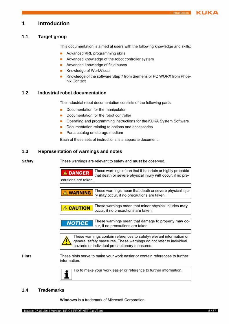
1.3 Representation of warnings and notes
Safety These warnings are relevant to safety and must be observed.
Hints These hints serve to make your work easier or contain references to further information.
1.4 Trademarks
Windows is a trademark of Microsoft Corporation.
These warnings mean that it is certain or highly probable that death or severe physical injury will occur, if no pre-
cautions are taken.
These warnings mean that death or severe physical inju-ry may occur, if no precautions are taken.
These warnings mean that minor physical injuries may occur, if no precautions are taken.
These warnings mean that damage to property may oc-cur, if no precautions are taken.
These warnings contain references to safety-relevant information or general safety measures. These warnings do not refer to individual hazards or individual precautionary measures.
Tip to make your work easier or reference to further information.
5 / 57 Issued: 07.03.2011 Version: KR C4 PROFINET 2.0 V3 en
6 / 57
KR C4 PROFINET 2.0
Step 7 are trademarks of Siemens AG.
PC WORX is a trademark of Phoenix Contact.
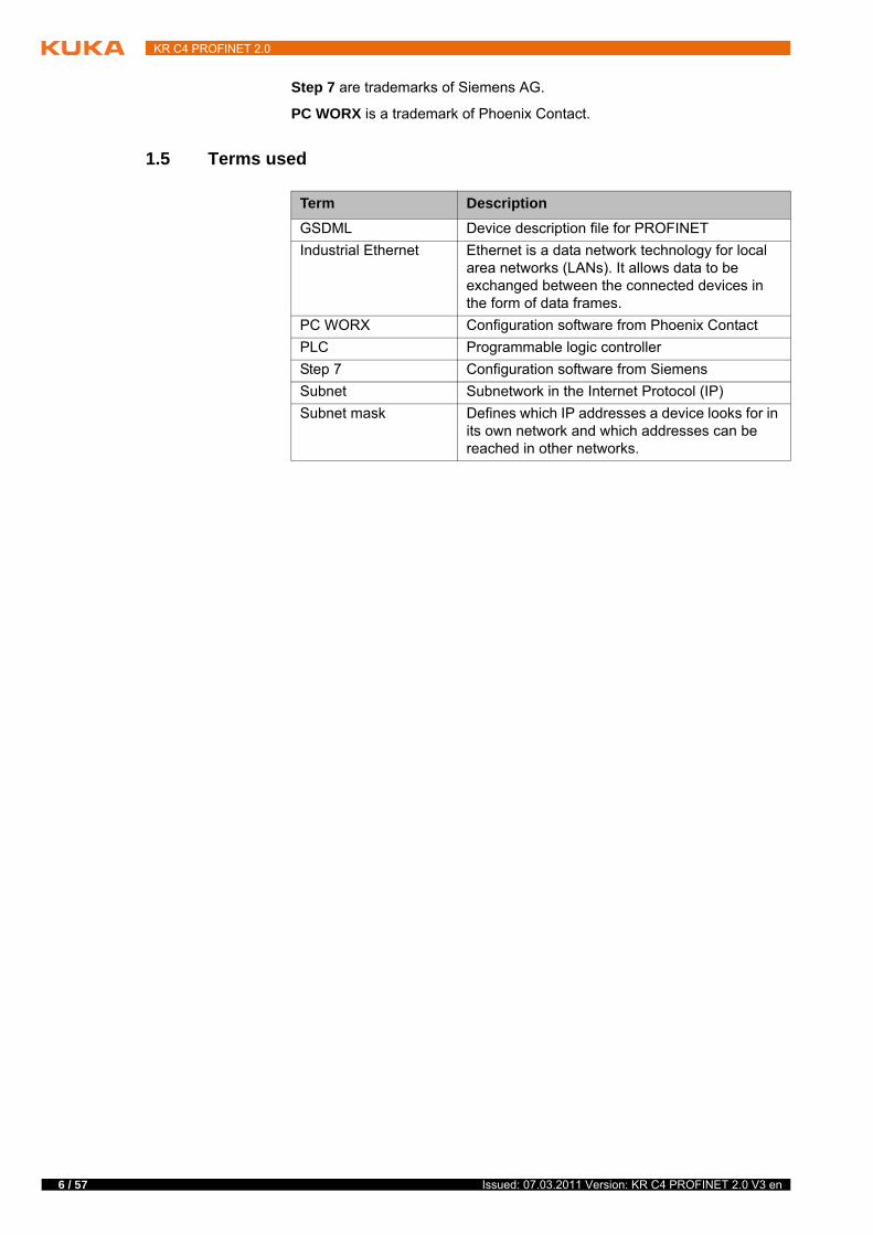
1.5 Terms used
Term Description
GSDML Device description file for PROFINET
Industrial Ethernet Ethernet is a data network technology for local area networks (LANs). It allows data to be exchanged between the connected devices in the form of data frames.
PC WORX Configuration software from Phoenix Contact
PLC Programmable logic controller
Step 7 Configuration software from Siemens
Subnet Subnetwork in the Internet Protocol (IP)
Subnet mask Defines which IP addresses a device looks for in its own network and which addresses can be reached in other networks.
Issued: 07.03.2011 Version: KR C4 PROFINET 2.0 V3 en
2 Product description
2 Product description
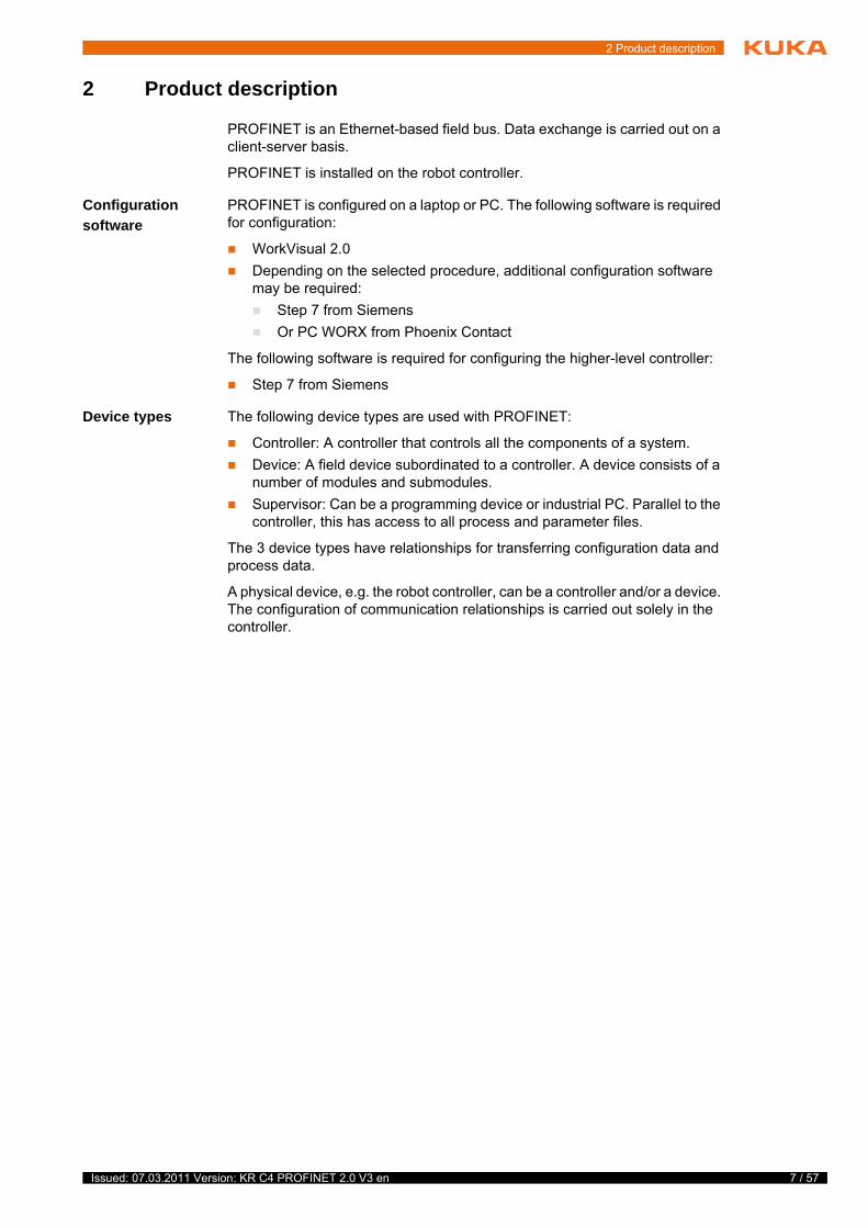
PROFINET is an Ethernet-based field bus. Data exchange is carried out on a client-server basis.
PROFINET is installed on the robot controller.
Configuration
software
PROFINET is configured on a laptop or PC. The following software is required for configuration:
WorkVisual 2.0
Depending on the selected procedure, additional configuration software may be required:
Step 7 from Siemens
Or PC WORX from Phoenix Contact
The following software is required for configuring the higher-level controller:
Step 7 from Siemens
Device types The following device types are used with PROFINET:
Controller: A controller that controls all the components of a system.
Device: A field device subordinated to a controller. A device consists of a number of modules and submodules.
Supervisor: Can be a programming device or industrial PC. Parallel to the controller, this has access to all process and parameter files.
The 3 device types have relationships for transferring configuration data and process data.
A physical device, e.g. the robot controller, can be a controller and/or a device. The configuration of communication relationships is carried out solely in the controller.
7 / 57 Issued: 07.03.2011 Version: KR C4 PROFINET 2.0 V3 en

8 / 57
KR C4 PROFINET 2.0
Issued: 07.03.2011 Version: KR C4 PROFINET 2.0 V3 en

3 Safety
3 Safety
This documentation contains safety instructions which refer specifically to the product described here. The fundamental safety information for the industrial robot can be found in the “Safety” chapter of the operating or assembly instruc-tions for the robot controller.
The “Safety” chapter in the operating or assembly in-structions must be observed. Death to persons, severe
physical injuries or considerable damage to property may otherwise result.
9 / 57 Issued: 07.03.2011 Version: KR C4 PROFINET 2.0 V3 en

10 / 57
KR C4 PROFINET 2.0
Issued: 07.03.2011 Version: KR C4 PROFINET 2.0 V3 en
4 Installation
4 Installation
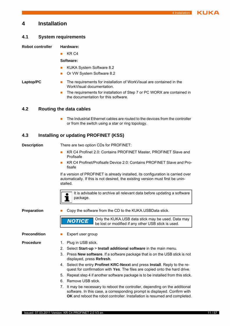
4.1 System requirements
Robot controller Hardware:
KR C4
Software:
KUKA System Software 8.2
Or VW System Software 8.2
Laptop/PC The requirements for installation of WorkVisual are contained in the WorkVisual documentation.
The requirements for installation of Step 7 or PC WORX are contained in the documentation for this software.
4.2 Routing the data cables
The Industrial Ethernet cables are routed to the devices from the controller or from the switch using a star or ring topology.
4.3 Installing or updating PROFINET (KSS)
Description There are two option CDs for PROFINET:
KR C4 Profinet 2.0: Contains PROFINET Master, PROFINET Slave and Profisafe
KR C4 Profinet/Profisafe Device 2.0: Contains PROFINET Slave and Pro-fisafe
If a version of PROFINET is already installed, its configuration is carried over automatically. If this is not desired, the existing version must first be unin-stalled.
Preparation Copy the software from the CD to the KUKA.USBData stick.
Precondition Expert user group
Procedure 1. Plug in USB stick.
2. Select Start-up > Install additional software in the main menu.
3. Press New software. If a software package that is on the USB stick is not displayed, press Refresh.
4. Select the entry Profinet KRC-Nexxt and press Install. Reply to the re-quest for confirmation with Yes. The files are copied onto the hard drive.
5. Repeat step 4 if another software package is to be installed from this stick.
6. Remove USB stick.
7. It may be necessary to reboot the controller, depending on the additional software. In this case, a corresponding prompt is displayed. Confirm with OK and reboot the robot controller. Installation is resumed and completed.
It is advisable to archive all relevant data before updating a software package.
Only the KUKA.USB data stick may be used. Data may be lost or modified if any other USB stick is used.
11 / 57 Issued: 07.03.2011 Version: KR C4 PROFINET 2.0 V3 en
12 / 57
KR C4 PROFINET 2.0
LOG file A LOG file is created under C:\KRC\ROBOTER\LOG.
4.4 Installing PROFINET (VSS)
KR C4 Profinet 2.0 is included in VSS 8.2. KR C4 Profinet 2.0 contains PRO-FINET Master, PROFINET Slave and Profisafe. To install PROFINET, the rel-evant check box must be activated during the setup for VSS 8.2.
4.5 Uninstalling PROFINET (KSS)
Precondition Expert user group
Procedure 1. Select Start-up > Install additional software in the main menu. All addi-tional programs installed are displayed.
2. Select the entry Profinet KRC-Nexxt and press Uninstall.
3. Answer the request for confirmation with Yes. PROFINET is uninstalled.
LOG file A LOG file is created under C:\KRC\ROBOTER\LOG.
It is advisable to archive all relevant data before uninstalling a soft-ware package.
Issued: 07.03.2011 Version: KR C4 PROFINET 2.0 V3 en
5 Configuration
5 Configuration
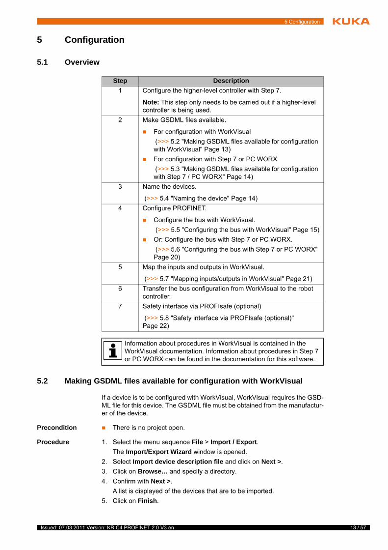
5.1 Overview
5.2 Making GSDML files available for configuration with WorkVisual
If a device is to be configured with WorkVisual, WorkVisual requires the GSD-ML file for this device. The GSDML file must be obtained from the manufactur-er of the device.
Precondition There is no project open.
Procedure 1. Select the menu sequence File > Import / Export.
The Import/Export Wizard window is opened.
2. Select Import device description file and click on Next >.
3. Click on Browse… and specify a directory.
4. Confirm with Next >.
A list is displayed of the devices that are to be imported.
5. Click on Finish.
Step Description
1 Configure the higher-level controller with Step 7.
Note: This step only needs to be carried out if a higher-level controller is being used.
2 Make GSDML files available.
For configuration with WorkVisual
(>>> 5.2 "Making GSDML files available for configuration with WorkVisual" Page 13)
For configuration with Step 7 or PC WORX
(>>> 5.3 "Making GSDML files available for configuration with Step 7 / PC WORX" Page 14)
3 Name the devices.
(>>> 5.4 "Naming the device" Page 14)
4 Configure PROFINET.
Configure the bus with WorkVisual.
(>>> 5.5 "Configuring the bus with WorkVisual" Page 15)
Or: Configure the bus with Step 7 or PC WORX.
(>>> 5.6 "Configuring the bus with Step 7 or PC WORX" Page 20)
5 Map the inputs and outputs in WorkVisual.
(>>> 5.7 "Mapping inputs/outputs in WorkVisual" Page 21)
6 Transfer the bus configuration from WorkVisual to the robot controller.
7 Safety interface via PROFIsafe (optional)
(>>> 5.8 "Safety interface via PROFIsafe (optional)" Page 22)
Information about procedures in WorkVisual is contained in the WorkVisual documentation. Information about procedures in Step 7 or PC WORX can be found in the documentation for this software.
13 / 57 Issued: 07.03.2011 Version: KR C4 PROFINET 2.0 V3 en
14 / 57
KR C4 PROFINET 2.0
The devices are imported.
6. Close the Import/Export Wizard window.
5.3 Making GSDML files available for configuration with Step 7 / PC WORX
If a KUKA robot controller is added as a device in Step 7 or PC WORX, this software requires the GSDML file for the KUKA robot controller.
Procedure 1. Copy the GSDML file of the KUKA robot controller.
File name: […]KRC-nexxt-Device[…]
The file can be found on the WorkVisual CD-ROM, in the following di-rectory: DeviceDescriptions\GSDML
2. Insert the file in Step 7 or PC WORX.
5.4 Naming the device
Description A PROFINET device is delivered without a name. In order to be able to use the device, it must first be assigned a unique name. This procedure is referred to as “Device naming”.
It is advisable to assign a logical name to the device. For example, if the device belongs to a certain tool, this should be obvious from the name.
Precondition A robot controller has been added and set as active.
Procedure 1. Expand the tree structure of the robot controller on the Hardware tab in the Project structure window.
2. Right-click on Bus Structure and select Add… from the context menu.
3. A window opens. Select the entry PROFINET Stack and confirm with OK. The entry is inserted in the tree structure.
4. Right-click on PROFINET Stack and select Settings from the context menu.
The Communication settings window is displayed.
5. Select the network adapter and confirm with OK.
6. Right-click on PROFINET Stack and select Connect from the context menu.
7. Right-click on PROFINET Stack and select Functions > Device list and PROFINET names from the context menu.
The Available devices window is displayed.
8. Double-click on the name of the desired device and change the name.
9. Save the entered name using Set device names....
5.4.1 Identifying the device
Precondition A robot controller has been added and set as active.
PROFINET Stack has been added and connected.
Procedure 1. Expand the tree structure of the robot controller on the Hardware tab in the Project structure window.
Do not use any spaces or special characters in the name.
Alternatively, the device can be renamed in Step 7 or any other soft-ware with a device naming function.
Issued: 07.03.2011 Version: KR C4 PROFINET 2.0 V3 en
5 Configuration
2. Right-click on PROFINET Stack and select Functions > Device list and PROFINET names from the context menu.
The Available devices window is displayed.
3. Select the desired device and click on Signal.
The device flashes.
4. To stop the flashing, click on Stop signaling.
5.4.2 Resetting the device configuration to factory settings
Precondition A robot controller has been added and set as active.
PROFINET Stack has been added and connected.
Procedure 1. Expand the tree structure of the robot controller on the Hardware tab in the Project structure window.
2. Right-click on PROFINET Stack and select Functions > Device list and PROFINET names from the context menu.
The Available devices window is displayed.
3. Select the desired device and click on Reset.
4. Answer the request for confirmation with Yes.
The configuration of the device is reset to the factory settings.
5.5 Configuring the bus with WorkVisual
5.5.1 Configuring the PROFINET master
Precondition A robot controller has been added and set as active.
PROFINET Stack has been added.
Procedure 1. Expand the tree structure of the robot controller on the Hardware tab in the Project structure window.
2. Right-click on PROFINET IO and select Add… from the context menu.
3. A window opens with a list of devices. Select the device used and confirm with OK. The device is inserted in the tree structure.
4. Right-click on the device in the tree structure and select Settings… from the context menu. A window with the device data is opened.
On the Network tab, fill out the following boxes:
Address; Subnet mask; Use a gateway; Gateway
Device name; Active on start-up; User ID; Activate diagnostic alarm
(>>> 5.5.1.1 "Device settings" Page 16)
5. The Modules tab displays the slots on the device. Assign the slots to the modules used.
6. If necessary, repeat steps 4 to 7 for further devices.
7. Save the device data with OK.
The inserted device must correspond to the actual de-vice used in reality. Substantial damage to property may
otherwise result.
15 / 57 Issued: 07.03.2011 Version: KR C4 PROFINET 2.0 V3 en
16 / 57
KR C4 PROFINET 2.0
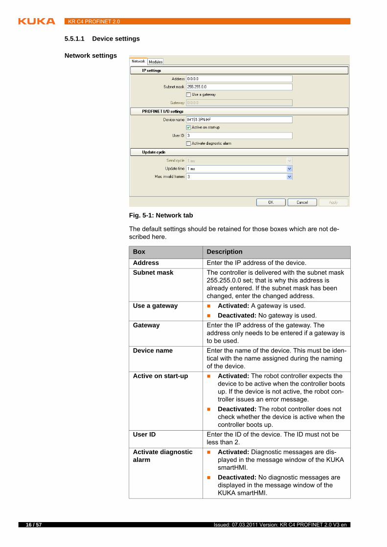
5.5.1.1 Device settings
Network settings
The default settings should be retained for those boxes which are not de-scribed here.
Fig. 5-1: Network tab
Box Description
Address Enter the IP address of the device.
Subnet mask The controller is delivered with the subnet mask 255.255.0.0 set; that is why this address is already entered. If the subnet mask has been changed, enter the changed address.
Use a gateway Activated: A gateway is used.
Deactivated: No gateway is used.
Gateway Enter the IP address of the gateway. The address only needs to be entered if a gateway is to be used.
Device name Enter the name of the device. This must be iden-tical with the name assigned during the naming of the device.
Active on start-up Activated: The robot controller expects the device to be active when the controller boots up. If the device is not active, the robot con-troller issues an error message.
Deactivated: The robot controller does not check whether the device is active when the controller boots up.
User ID Enter the ID of the device. The ID must not be less than 2.
Activate diagnostic alarm
Activated: Diagnostic messages are dis-played in the message window of the KUKA smartHMI.
Deactivated: No diagnostic messages are displayed in the message window of the KUKA smartHMI.
Issued: 07.03.2011 Version: KR C4 PROFINET 2.0 V3 en
5 Configuration
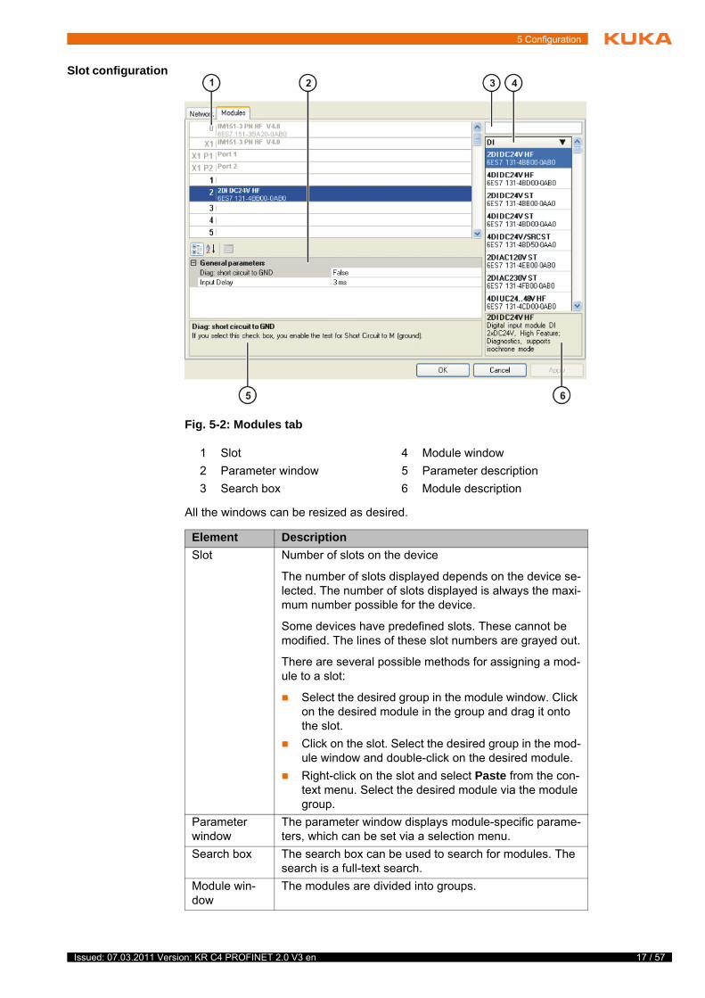
Slot configuration
All the windows can be resized as desired.
Fig. 5-2: Modules tab
1 Slot 4 Module window
2 Parameter window 5 Parameter description
3 Search box 6 Module description
Element Description
Slot Number of slots on the device
The number of slots displayed depends on the device se-lected. The number of slots displayed is always the maxi-mum number possible for the device.
Some devices have predefined slots. These cannot be modified. The lines of these slot numbers are grayed out.
There are several possible methods for assigning a mod-ule to a slot:
Select the desired group in the module window. Click on the desired module in the group and drag it onto the slot.
Click on the slot. Select the desired group in the mod-ule window and double-click on the desired module.
Right-click on the slot and select Paste from the con-text menu. Select the desired module via the module group.
Parameter window
The parameter window displays module-specific parame-ters, which can be set via a selection menu.
Search box The search box can be used to search for modules. The search is a full-text search.
Module win-dow
The modules are divided into groups.
17 / 57 Issued: 07.03.2011 Version: KR C4 PROFINET 2.0 V3 en
18 / 57
KR C4 PROFINET 2.0
5.5.1.2 Activating fast startup
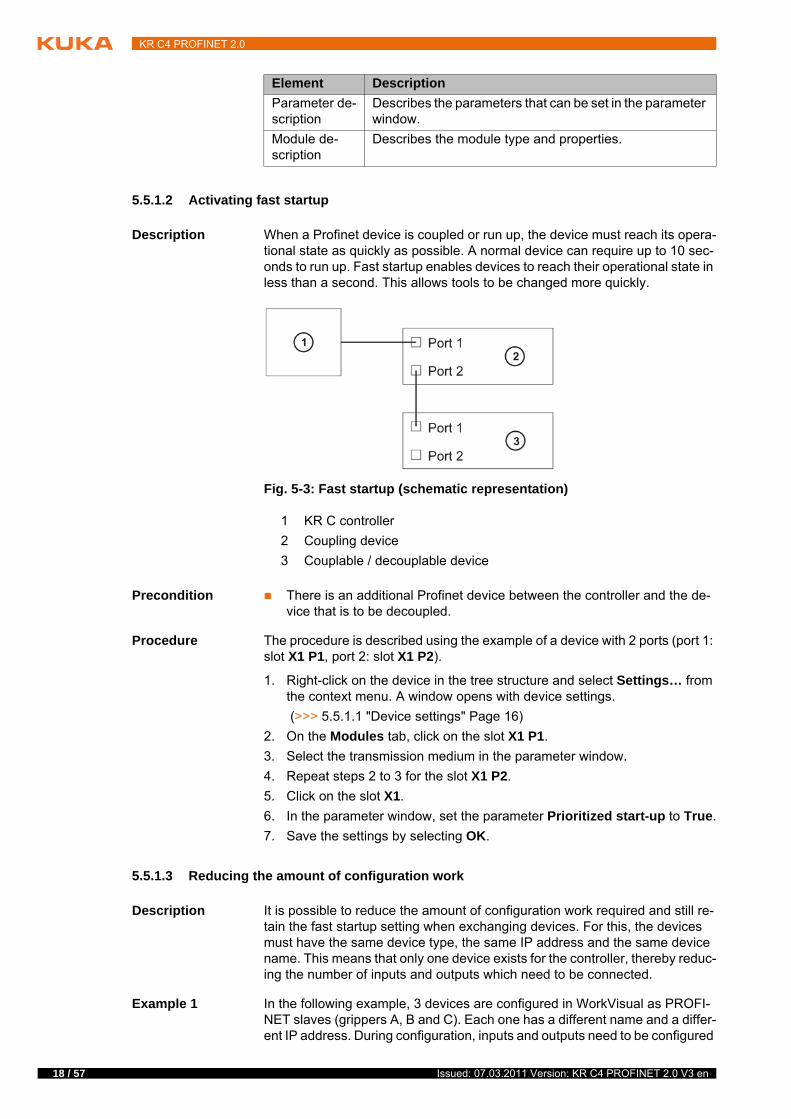
Description When a Profinet device is coupled or run up, the device must reach its opera-tional state as quickly as possible. A normal device can require up to 10 sec-onds to run up. Fast startup enables devices to reach their operational state in less than a second. This allows tools to be changed more quickly.
Precondition There is an additional Profinet device between the controller and the de-vice that is to be decoupled.
Procedure The procedure is described using the example of a device with 2 ports (port 1: slot X1 P1, port 2: slot X1 P2).
1. Right-click on the device in the tree structure and select Settings… from the context menu. A window opens with device settings.
(>>> 5.5.1.1 "Device settings" Page 16)
2. On the Modules tab, click on the slot X1 P1.
3. Select the transmission medium in the parameter window.
4. Repeat steps 2 to 3 for the slot X1 P2.
5. Click on the slot X1.
6. In the parameter window, set the parameter Prioritized start-up to True.
7. Save the settings by selecting OK.
5.5.1.3 Reducing the amount of configuration work
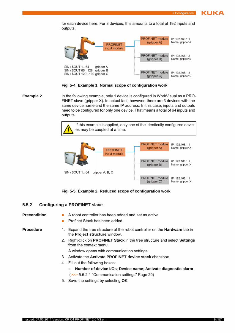
Description It is possible to reduce the amount of configuration work required and still re-tain the fast startup setting when exchanging devices. For this, the devices must have the same device type, the same IP address and the same device name. This means that only one device exists for the controller, thereby reduc-ing the number of inputs and outputs which need to be connected.
Example 1 In the following example, 3 devices are configured in WorkVisual as PROFI-NET slaves (grippers A, B and C). Each one has a different name and a differ-ent IP address. During configuration, inputs and outputs need to be configured
Parameter de-scription
Describes the parameters that can be set in the parameter window.
Module de-scription
Describes the module type and properties.
Element Description
Fig. 5-3: Fast startup (schematic representation)
1 KR C controller
2 Coupling device
3 Couplable / decouplable device
Issued: 07.03.2011 Version: KR C4 PROFINET 2.0 V3 en
5 Configuration
for each device here. For 3 devices, this amounts to a total of 192 inputs and outputs.
Example 2 In the following example, only 1 device is configured in WorkVisual as a PRO-FINET slave (gripper X). In actual fact, however, there are 3 devices with the same device name and the same IP address. In this case, inputs and outputs need to be configured for only one device. That means a total of 64 inputs and outputs.
5.5.2 Configuring a PROFINET slave
Precondition A robot controller has been added and set as active.
Profinet Stack has been added.
Procedure 1. Expand the tree structure of the robot controller on the Hardware tab in the Project structure window.
2. Right-click on PROFINET Stack in the tree structure and select Settings from the context menu.
A window opens with communication settings.
3. Activate the Activate PROFINET device stack checkbox.
4. Fill out the following boxes:
Number of device I/Os; Device name; Activate diagnostic alarm
(>>> 5.5.2.1 "Communication settings" Page 20)
5. Save the settings by selecting OK.
Fig. 5-4: Example 1: Normal scope of configuration work
If this example is applied, only one of the identically configured devic-es may be coupled at a time.
Fig. 5-5: Example 2: Reduced scope of configuration work
19 / 57 Issued: 07.03.2011 Version: KR C4 PROFINET 2.0 V3 en
20 / 57
KR C4 PROFINET 2.0
5.5.2.1 Communication settings
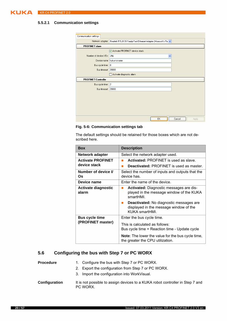
The default settings should be retained for those boxes which are not de-scribed here.
5.6 Configuring the bus with Step 7 or PC WORX
Procedure 1. Configure the bus with Step 7 or PC WORX.
2. Export the configuration from Step 7 or PC WORX.
3. Import the configuration into WorkVisual.
Configuration It is not possible to assign devices to a KUKA robot controller in Step 7 and PC WORX.
Fig. 5-6: Communication settings tab
Box Description
Network adapter Select the network adapter used.
Activate PROFINET device stack
Activated: PROFINET is used as slave.
Deactivated: PROFINET is used as master.
Number of device I/Os
Select the number of inputs and outputs that the device has.
Device name Enter the name of the device.
Activate diagnostic alarm
Activated: Diagnostic messages are dis-played in the message window of the KUKA smartHMI.
Deactivated: No diagnostic messages are displayed in the message window of the KUKA smartHMI.
Bus cycle time (PROFINET master)
Enter the bus cycle time.
This is calculated as follows: Bus cycle time = Reaction time - Update cycle
Note: The lower the value for the bus cycle time, the greater the CPU utilization.
Issued: 07.03.2011 Version: KR C4 PROFINET 2.0 V3 en
5 Configuration
Remedy in Step 7:
1. Define a CP1616 as a controller.
2. Assign the required devices to the CP1616.
Remedy in PC WORX:
1. Create a project ILC 350 PN.
2. Assign the required devices to the project.
When a configuration of this type is imported into WorkVisual, WorkVisual ig-nores the CP1616/ILC 350 PN and takes the KUKA robot controller as the controller.
Export To enable the configuration from Step 7 or PC WORX to be imported into WorkVisual, the following options must be set for the export:
Exporting from Step 7:
Activate the checkboxes Export default values, Export symbols, Export subnets.
Activate the radiobox Readable.
Exporting from PC WORX:
Select Export PLCopen xml file.
Import
5.7 Mapping inputs/outputs in WorkVisual
Procedure Map the inputs/outputs in WorkVisual.
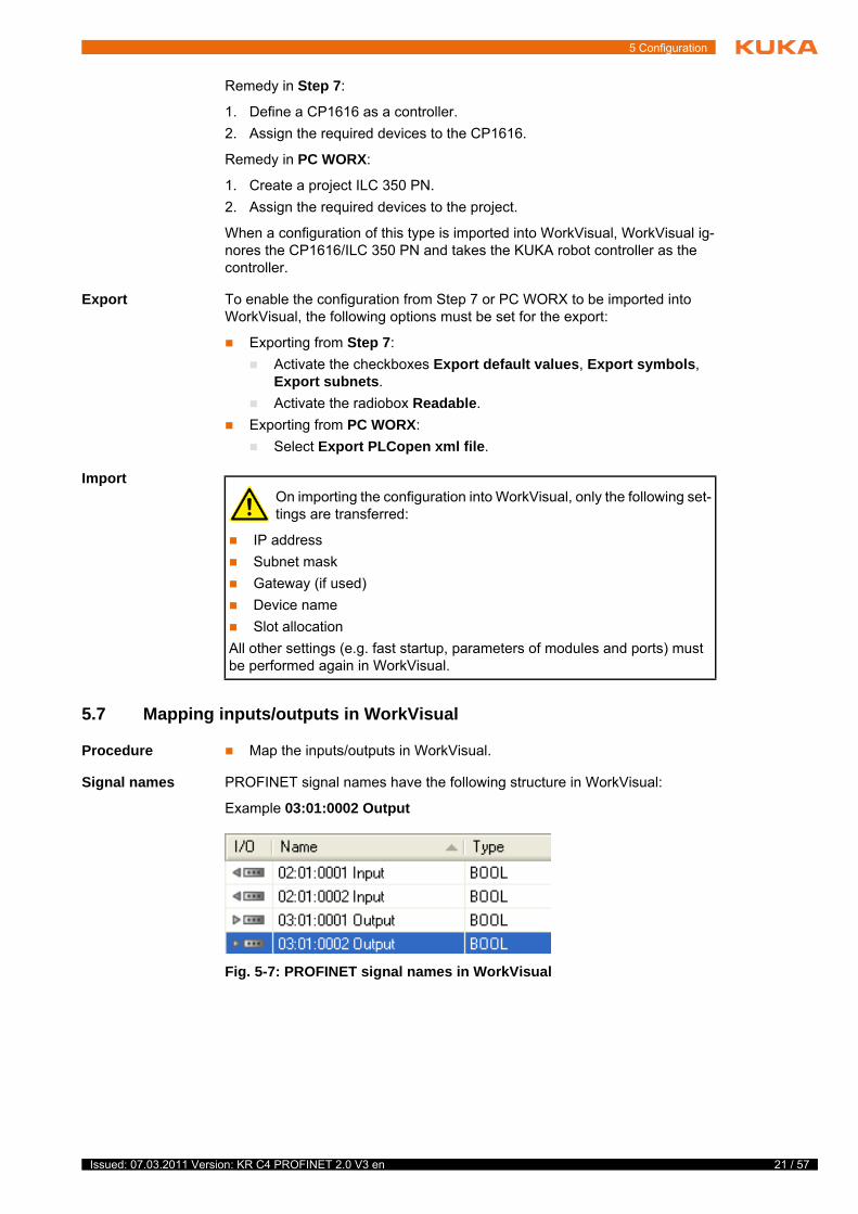
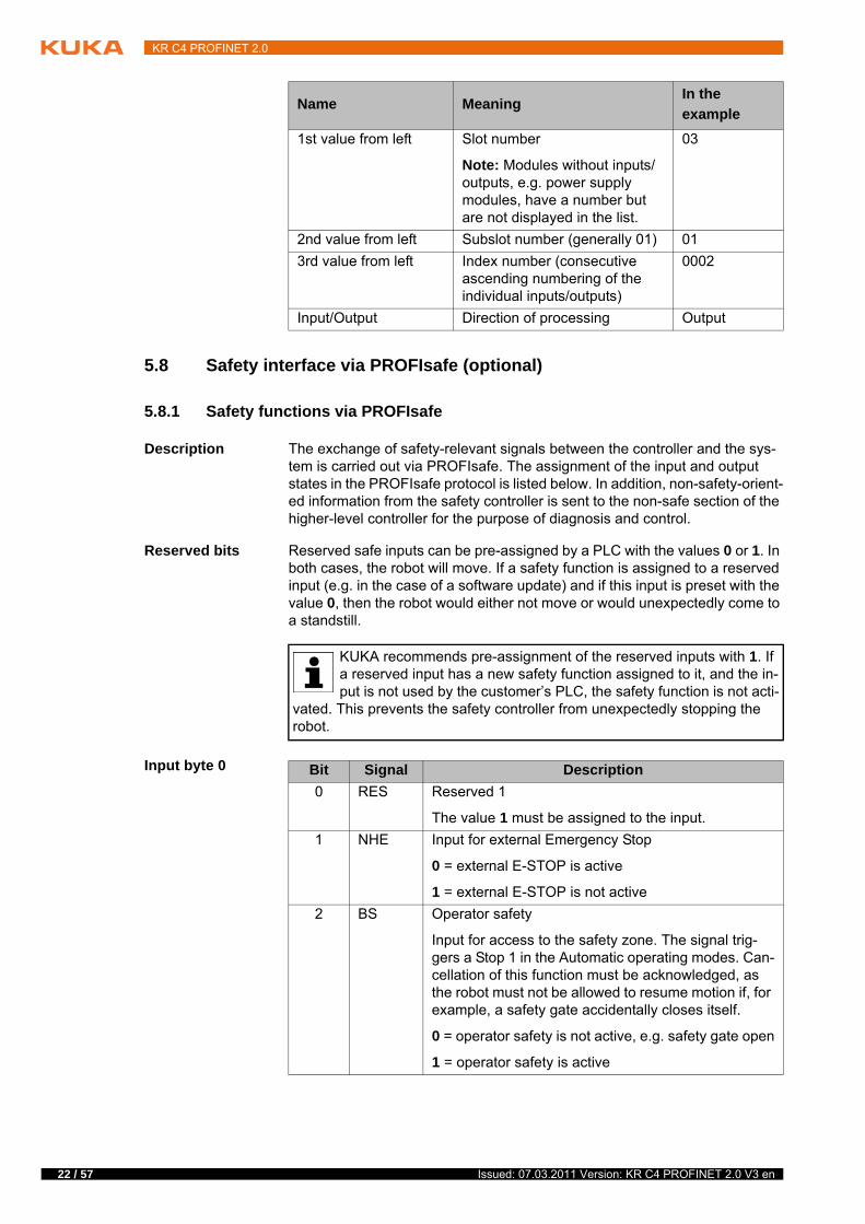
Signal names PROFINET signal names have the following structure in WorkVisual:
Example 03:01:0002 Output
On importing the configuration into WorkVisual, only the following set-tings are transferred:
IP address
Subnet mask
Gateway (if used)
Device name
Slot allocation
All other settings (e.g. fast startup, parameters of modules and ports) must be performed again in WorkVisual.
Fig. 5-7: PROFINET signal names in WorkVisual
21 / 57 Issued: 07.03.2011 Version: KR C4 PROFINET 2.0 V3 en
22 / 57
KR C4 PROFINET 2.0
5.8 Safety interface via PROFIsafe (optional)
5.8.1 Safety functions via PROFIsafe
Description The exchange of safety-relevant signals between the controller and the sys-tem is carried out via PROFIsafe. The assignment of the input and output states in the PROFIsafe protocol is listed below. In addition, non-safety-orient-ed information from the safety controller is sent to the non-safe section of the higher-level controller for the purpose of diagnosis and control.
Reserved bits Reserved safe inputs can be pre-assigned by a PLC with the values 0 or 1. In both cases, the robot will move. If a safety function is assigned to a reserved input (e.g. in the case of a software update) and if this input is preset with the value 0, then the robot would either not move or would unexpectedly come to a standstill.
Input byte 0
Name MeaningIn the
example
1st value from left Slot number
Note: Modules without inputs/outputs, e.g. power supply modules, have a number but are not displayed in the list.
03
2nd value from left Subslot number (generally 01) 01
3rd value from left Index number (consecutive ascending numbering of the individual inputs/outputs)
0002
Input/Output Direction of processing Output
KUKA recommends pre-assignment of the reserved inputs with 1. If a reserved input has a new safety function assigned to it, and the in-put is not used by the customer’s PLC, the safety function is not acti-
vated. This prevents the safety controller from unexpectedly stopping the robot.
Bit Signal Description
0 RES Reserved 1
The value 1 must be assigned to the input.
1 NHE Input for external Emergency Stop
0 = external E-STOP is active
1 = external E-STOP is not active
2 BS Operator safety
Input for access to the safety zone. The signal trig-gers a Stop 1 in the Automatic operating modes. Can-cellation of this function must be acknowledged, as the robot must not be allowed to resume motion if, for example, a safety gate accidentally closes itself.
0 = operator safety is not active, e.g. safety gate open
1 = operator safety is active
Issued: 07.03.2011 Version: KR C4 PROFINET 2.0 V3 en
5 Configuration
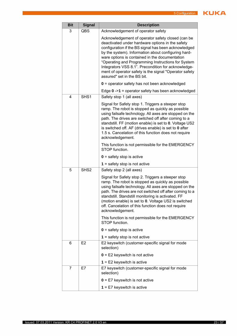
3 QBS Acknowledgement of operator safety
Acknowledgement of operator safety closed (can be deactivated under hardware options in the safety configuration if the BS signal has been acknowledged by the system). Information about configuring hard-ware options is contained in the documentation “Operating and Programming Instructions for System Integrators VSS 8.1”. Precondition for acknowledge-ment of operator safety is the signal "Operator safety assured" set in the BS bit.
0 = operator safety has not been acknowledged
Edge 0 ->1 = operator safety has been acknowledged
4 SHS1 Safety stop 1 (all axes)
Signal for Safety stop 1. Triggers a steeper stop ramp. The robot is stopped as quickly as possible using failsafe technology. All axes are stopped on the path. The drives are switched off after coming to a standstill. FF (motion enable) is set to 0. Voltage US2 is switched off. AF (drives enable) is set to 0 after 1.5 s. Cancelation of this function does not require acknowledgement.
This function is not permissible for the EMERGENCY STOP function.
0 = safety stop is active
1 = safety stop is not active
5 SHS2 Safety stop 2 (all axes)
Signal for Safety stop 2. Triggers a steeper stop ramp. The robot is stopped as quickly as possible using failsafe technology. All axes are stopped on the path. The drives are not switched off after coming to a standstill. Standstill monitoring is activated. FF (motion enable) is set to 0. Voltage US2 is switched off. Cancelation of this function does not require acknowledgement.
This function is not permissible for the EMERGENCY STOP function.
0 = safety stop is active
1 = safety stop is not active
6 E2 E2 keyswitch (customer-specific signal for mode selection)
0 = E2 keyswitch is not active
1 = E2 keyswitch is active
7 E7 E7 keyswitch (customer-specific signal for mode selection)
0 = E7 keyswitch is not active
1 = E7 keyswitch is active
Bit Signal Description
23 / 57 Issued: 07.03.2011 Version: KR C4 PROFINET 2.0 V3 en
24 / 57
KR C4 PROFINET 2.0
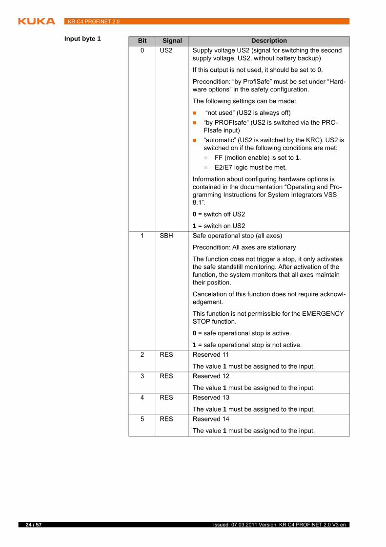
Input byte 1 Bit Signal Description
0 US2 Supply voltage US2 (signal for switching the second supply voltage, US2, without battery backup)
If this output is not used, it should be set to 0.
Precondition: “by ProfiSafe” must be set under “Hard-ware options” in the safety configuration.
The following settings can be made:
“not used” (US2 is always off)
“by PROFIsafe” (US2 is switched via the PRO-FIsafe input)
“automatic” (US2 is switched by the KRC). US2 is switched on if the following conditions are met:
FF (motion enable) is set to 1.
E2/E7 logic must be met.
Information about configuring hardware options is contained in the documentation “Operating and Pro-gramming Instructions for System Integrators VSS 8.1”.
0 = switch off US2
1 = switch on US2
1 SBH Safe operational stop (all axes)
Precondition: All axes are stationary
The function does not trigger a stop, it only activates the safe standstill monitoring. After activation of the function, the system monitors that all axes maintain their position.
Cancelation of this function does not require acknowl-edgement.
This function is not permissible for the EMERGENCY STOP function.
0 = safe operational stop is active.
1 = safe operational stop is not active.
2 RES Reserved 11
The value 1 must be assigned to the input.
3 RES Reserved 12
The value 1 must be assigned to the input.
4 RES Reserved 13
The value 1 must be assigned to the input.
5 RES Reserved 14
The value 1 must be assigned to the input.
Issued: 07.03.2011 Version: KR C4 PROFINET 2.0 V3 en
5 Configuration
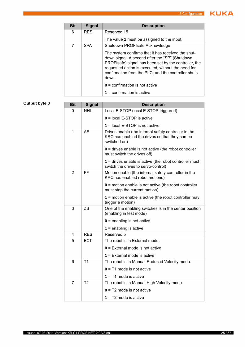
Output byte 0
6 RES Reserved 15
The value 1 must be assigned to the input.
7 SPA Shutdown PROFIsafe Acknowledge
The system confirms that it has received the shut-down signal. A second after the “SP” (Shutdown PROFIsafe) signal has been set by the controller, the requested action is executed, without the need for confirmation from the PLC, and the controller shuts down.
0 = confirmation is not active
1 = confirmation is active
Bit Signal Description
Bit Signal Description
0 NHL Local E-STOP (local E-STOP triggered)
0 = local E-STOP is active
1 = local E-STOP is not active
1 AF Drives enable (the internal safety controller in the KRC has enabled the drives so that they can be switched on)
0 = drives enable is not active (the robot controller must switch the drives off)
1 = drives enable is active (the robot controller must switch the drives to servo-control)
2 FF Motion enable (the internal safety controller in the KRC has enabled robot motions)
0 = motion enable is not active (the robot controller must stop the current motion)
1 = motion enable is active (the robot controller may trigger a motion)
3 ZS One of the enabling switches is in the center position (enabling in test mode)
0 = enabling is not active
1 = enabling is active
4 RES Reserved 5
5 EXT The robot is in External mode.
0 = External mode is not active
1 = External mode is active
6 T1 The robot is in Manual Reduced Velocity mode.
0 = T1 mode is not active
1 = T1 mode is active
7 T2 The robot is in Manual High Velocity mode.
0 = T2 mode is not active
1 = T2 mode is active
25 / 57 Issued: 07.03.2011 Version: KR C4 PROFINET 2.0 V3 en
26 / 57
KR C4 PROFINET 2.0
Output byte 1
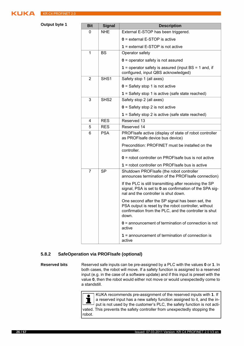
5.8.2 SafeOperation via PROFIsafe (optional)
Reserved bits Reserved safe inputs can be pre-assigned by a PLC with the values 0 or 1. In both cases, the robot will move. If a safety function is assigned to a reserved input (e.g. in the case of a software update) and if this input is preset with the value 0, then the robot would either not move or would unexpectedly come to a standstill.
Bit Signal Description
0 NHE External E-STOP has been triggered.
0 = external E-STOP is active
1 = external E-STOP is not active
1 BS Operator safety
0 = operator safety is not assured
1 = operator safety is assured (input BS = 1 and, if configured, input QBS acknowledged)
2 SHS1 Safety stop 1 (all axes)
0 = Safety stop 1 is not active
1 = Safety stop 1 is active (safe state reached)
3 SHS2 Safety stop 2 (all axes)
0 = Safety stop 2 is not active
1 = Safety stop 2 is active (safe state reached)
4 RES Reserved 13
5 RES Reserved 14
6 PSA PROFIsafe active (display of state of robot controller as PROFIsafe device bus device)
Precondition: PROFINET must be installed on the controller.
0 = robot controller on PROFIsafe bus is not active
1 = robot controller on PROFIsafe bus is active
7 SP Shutdown PROFIsafe (the robot controller announces termination of the PROFIsafe connection)
If the PLC is still transmitting after receiving the SP signal, PSA is set to 0 as confirmation of the SPA sig-nal and the controller is shut down.
One second after the SP signal has been set, the PSA output is reset by the robot controller, without confirmation from the PLC, and the controller is shut down.
0 = announcement of termination of connection is not active
1 = announcement of termination of connection is active
KUKA recommends pre-assignment of the reserved inputs with 1. If a reserved input has a new safety function assigned to it, and the in-put is not used by the customer’s PLC, the safety function is not acti-
vated. This prevents the safety controller from unexpectedly stopping the robot.
Issued: 07.03.2011 Version: KR C4 PROFINET 2.0 V3 en
5 Configuration
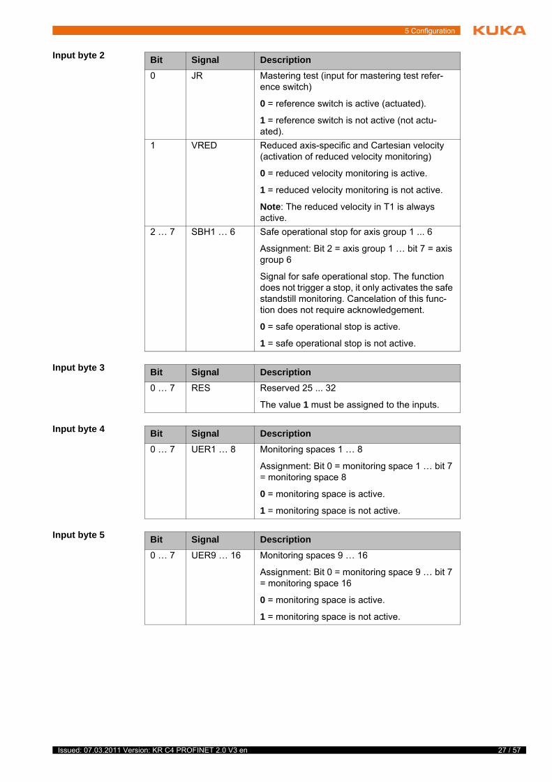
Input byte 2
Input byte 3
Input byte 4
Input byte 5
Bit Signal Description
0 JR Mastering test (input for mastering test refer-ence switch)
0 = reference switch is active (actuated).
1 = reference switch is not active (not actu-ated).
1 VRED Reduced axis-specific and Cartesian velocity (activation of reduced velocity monitoring)
0 = reduced velocity monitoring is active.
1 = reduced velocity monitoring is not active.
Note: The reduced velocity in T1 is always active.
2 … 7 SBH1 … 6 Safe operational stop for axis group 1 ... 6
Assignment: Bit 2 = axis group 1 … bit 7 = axis group 6
Signal for safe operational stop. The function does not trigger a stop, it only activates the safe standstill monitoring. Cancelation of this func-tion does not require acknowledgement.
0 = safe operational stop is active.
1 = safe operational stop is not active.
Bit Signal Description
0 … 7 RES Reserved 25 ... 32
The value 1 must be assigned to the inputs.
Bit Signal Description
0 … 7 UER1 … 8 Monitoring spaces 1 … 8
Assignment: Bit 0 = monitoring space 1 … bit 7 = monitoring space 8
0 = monitoring space is active.
1 = monitoring space is not active.
Bit Signal Description
0 … 7 UER9 … 16 Monitoring spaces 9 … 16
Assignment: Bit 0 = monitoring space 9 … bit 7 = monitoring space 16
0 = monitoring space is active.
1 = monitoring space is not active.
27 / 57 Issued: 07.03.2011 Version: KR C4 PROFINET 2.0 V3 en
28 / 57
KR C4 PROFINET 2.0
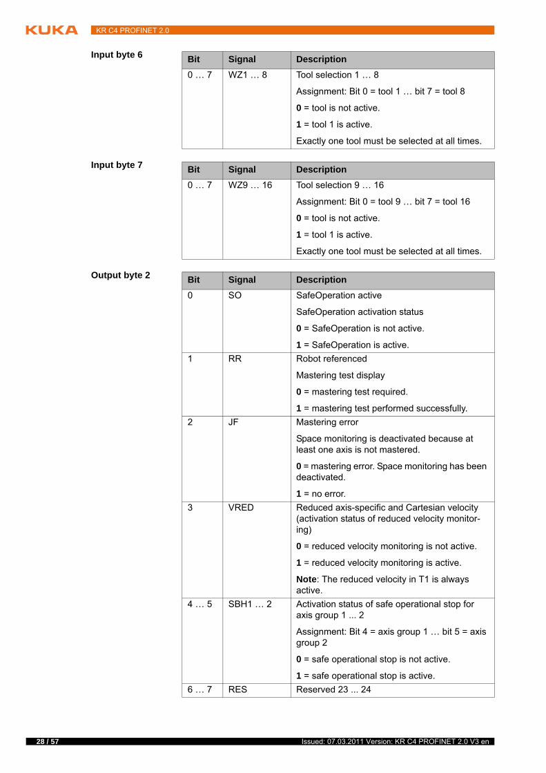
Input byte 6
Input byte 7
Output byte 2
Bit Signal Description
0 … 7 WZ1 … 8 Tool selection 1 … 8
Assignment: Bit 0 = tool 1 … bit 7 = tool 8
0 = tool is not active.
1 = tool 1 is active.
Exactly one tool must be selected at all times.
Bit Signal Description
0 … 7 WZ9 … 16 Tool selection 9 … 16
Assignment: Bit 0 = tool 9 … bit 7 = tool 16
0 = tool is not active.
1 = tool 1 is active.
Exactly one tool must be selected at all times.
Bit Signal Description
0 SO SafeOperation active
SafeOperation activation status
0 = SafeOperation is not active.
1 = SafeOperation is active.
1 RR Robot referenced
Mastering test display
0 = mastering test required.
1 = mastering test performed successfully.
2 JF Mastering error
Space monitoring is deactivated because at least one axis is not mastered.
0 = mastering error. Space monitoring has been deactivated.
1 = no error.
3 VRED Reduced axis-specific and Cartesian velocity (activation status of reduced velocity monitor-ing)
0 = reduced velocity monitoring is not active.
1 = reduced velocity monitoring is active.
Note: The reduced velocity in T1 is always active.
4 … 5 SBH1 … 2 Activation status of safe operational stop for axis group 1 ... 2
Assignment: Bit 4 = axis group 1 … bit 5 = axis group 2
0 = safe operational stop is not active.
1 = safe operational stop is active.
6 … 7 RES Reserved 23 ... 24
Issued: 07.03.2011 Version: KR C4 PROFINET 2.0 V3 en
5 Configuration
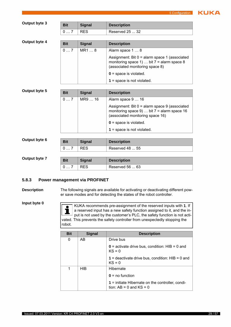
Output byte 3
Output byte 4
Output byte 5
Output byte 6
Output byte 7
5.8.3 Power management via PROFINET
Description The following signals are available for activating or deactivating different pow-er save modes and for detecting the states of the robot controller.
Input byte 0
Bit Signal Description
0 … 7 RES Reserved 25 ... 32
Bit Signal Description
0 … 7 MR1 … 8 Alarm space 1 … 8
Assignment: Bit 0 = alarm space 1 (associated monitoring space 1) … bit 7 = alarm space 8 (associated monitoring space 8)
0 = space is violated.
1 = space is not violated.
Bit Signal Description
0 … 7 MR9 … 16 Alarm space 9 … 16
Assignment: Bit 0 = alarm space 9 (associated monitoring space 9) … bit 7 = alarm space 16 (associated monitoring space 16)
0 = space is violated.
1 = space is not violated.
Bit Signal Description
0 … 7 RES Reserved 48 ... 55
Bit Signal Description
0 … 7 RES Reserved 56 ... 63
KUKA recommends pre-assignment of the reserved inputs with 1. If a reserved input has a new safety function assigned to it, and the in-put is not used by the customer’s PLC, the safety function is not acti-
vated. This prevents the safety controller from unexpectedly stopping the robot.
Bit Signal Description
0 AB Drive bus
0 = activate drive bus, condition: HIB = 0 and KS = 0
1 = deactivate drive bus, condition: HIB = 0 and KS = 0
1 HIB Hibernate
0 = no function
1 = initiate Hibernate on the controller, condi-tion: AB = 0 and KS = 0
29 / 57 Issued: 07.03.2011 Version: KR C4 PROFINET 2.0 V3 en
30 / 57
KR C4 PROFINET 2.0
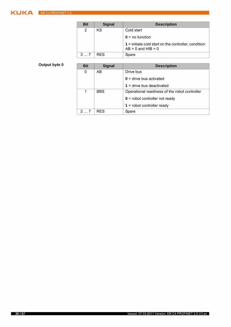
Output byte 0
2 KS Cold start
0 = no function
1 = initiate cold start on the controller, condition: AB = 0 and HIB = 0
3 … 7 RES Spare
Bit Signal Description
Bit Signal Description
0 AB Drive bus
0 = drive bus activated
1 = drive bus deactivated
1 BBS Operational readiness of the robot controller
0 = robot controller not ready
1 = robot controller ready
2 … 7 RES Spare
Issued: 07.03.2011 Version: KR C4 PROFINET 2.0 V3 en
6 Operation
6 Operation
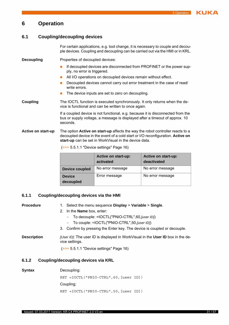
6.1 Coupling/decoupling devices
For certain applications, e.g. tool change, it is necessary to couple and decou-ple devices. Coupling and decoupling can be carried out via the HMI or in KRL.
Decoupling Properties of decoupled devices:
If decoupled devices are disconnected from PROFINET or the power sup-ply, no error is triggered.
All I/O operations on decoupled devices remain without effect.
Decoupled devices cannot carry out error treatment in the case of read/write errors.
The device inputs are set to zero on decoupling.
Coupling The IOCTL function is executed synchronously. It only returns when the de-vice is functional and can be written to once again.
If a coupled device is not functional, e.g. because it is disconnected from the bus or supply voltage, a message is displayed after a timeout of approx. 10 seconds.
Active on start-up The option Active on start-up affects the way the robot controller reacts to a decoupled device in the event of a cold start or I/O reconfiguration. Active on start-up can be set in WorkVisual in the device data.
(>>> 5.5.1.1 "Device settings" Page 16)
6.1.1 Coupling/decoupling devices via the HMI
Procedure 1. Select the menu sequence Display > Variable > Single.
2. In the Name box, enter:
To decouple: =IOCTL("PNIO-CTRL",60,[user ID])
To couple: =IOCTL("PNIO-CTRL",50,[user ID])
3. Confirm by pressing the Enter key. The device is coupled or decouple.
Description [User ID]: The user ID is displayed in WorkVisual in the User ID box in the de-vice settings.
(>>> 5.5.1.1 "Device settings" Page 16)
6.1.2 Coupling/decoupling devices via KRL
Syntax Decoupling:
RET =IOCTL("PNIO-CTRL",60,[user ID])
Coupling:
RET =IOCTL("PNIO-CTRL",50,[user ID])
Active on start-up: activated
Active on start-up: deactivated
Device coupled No error message No error message
Device
decoupled
Error message No error message
31 / 57 Issued: 07.03.2011 Version: KR C4 PROFINET 2.0 V3 en
32 / 57
KR C4 PROFINET 2.0
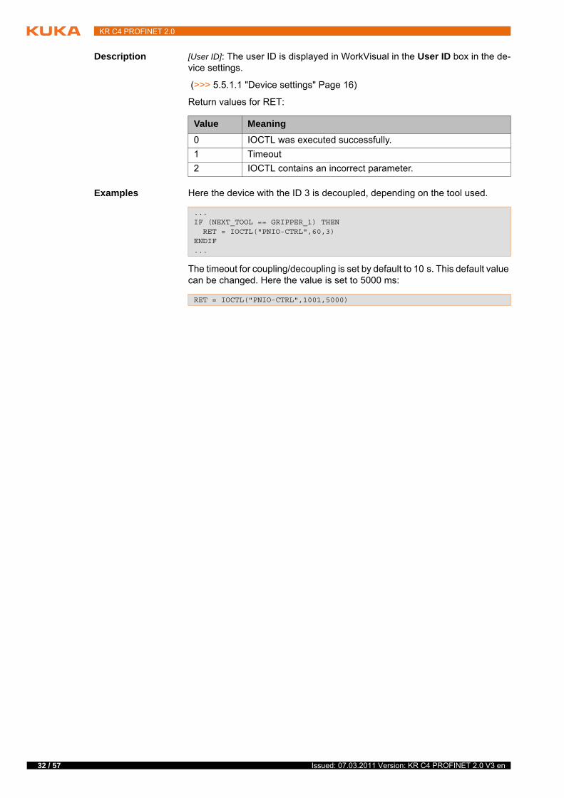
Description [User ID]: The user ID is displayed in WorkVisual in the User ID box in the de-vice settings.
(>>> 5.5.1.1 "Device settings" Page 16)
Return values for RET:
Examples Here the device with the ID 3 is decoupled, depending on the tool used.
The timeout for coupling/decoupling is set by default to 10 s. This default value can be changed. Here the value is set to 5000 ms:
Value Meaning
0 IOCTL was executed successfully.
1 Timeout
2 IOCTL contains an incorrect parameter.
... IF (NEXT_TOOL == GRIPPER_1) THEN RET = IOCTL("PNIO-CTRL",60,3) ENDIF ...
RET = IOCTL("PNIO-CTRL",1001,5000)
Issued: 07.03.2011 Version: KR C4 PROFINET 2.0 V3 en
7 Programming
7 Programming
7.1 Acyclic communication
In addition to typical I/O communication, asynchronous communication may also be necessary between applications and the I/O driver.
Examples:
Requesting data from the higher-level controller.
Parameterizing I/O modules during operation. (Only possible for modules with the relevant functionality.)
7.1.1 Acyclic data to the devices (master ring)
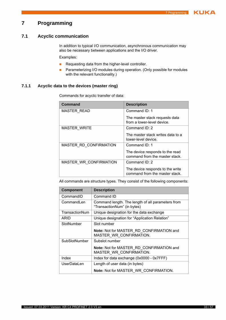
Commands for acyclic transfer of data:
All commands are structure types. They consist of the following components:
Command Description
MASTER_READ Command ID: 1
The master stack requests data from a lower-level device.
MASTER_WRITE Command ID: 2
The master stack writes data to a lower-level device.
MASTER_RD_CONFIRMATION Command ID: 1
The device responds to the read command from the master stack.
MASTER_WR_CONFIRMATION Command ID: 2
The device responds to the write command from the master stack.
Component Description
CommandID Command ID
CommandLen Command length. The length of all parameters from “TransactionNum” (in bytes)
TransactionNum Unique designation for the data exchange
ARID Unique designation for “Application Relation”
SlotNumber Slot number
Note: Not for MASTER_RD_CONFIRMATION and MASTER_WR_CONFIRMATION.
SubSlotNumber Subslot number
Note: Not for MASTER_RD_CONFIRMATION and MASTER_WR_CONFIRMATION.
Index Index for data exchange (0x0000 - 0x7FFF)
UserDataLen Length of user data (in bytes)
Note: Not for MASTER_WR_CONFIRMATION.
33 / 57 Issued: 07.03.2011 Version: KR C4 PROFINET 2.0 V3 en
34 / 57
KR C4 PROFINET 2.0
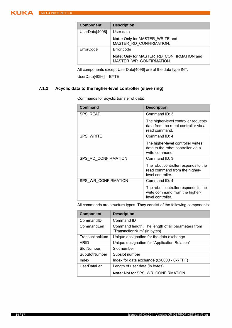
All components except UserData[4096] are of the data type INT.
UserData[4096] = BYTE
7.1.2 Acyclic data to the higher-level controller (slave ring)
Commands for acyclic transfer of data:
All commands are structure types. They consist of the following components:
UserData[4096] User data
Note: Only for MASTER_WRITE and MASTER_RD_CONFIRMATION.
ErrorCode Error code
Note: Only for MASTER_RD_CONFIRMATION and MASTER_WR_CONFIRMATION.
Component Description
Command Description
SPS_READ Command ID: 3
The higher-level controller requests data from the robot controller via a read command.
SPS_WRITE Command ID: 4
The higher-level controller writes data to the robot controller via a write command.
SPS_RD_CONFIRMATION Command ID: 3
The robot controller responds to the read command from the higher-level controller.
SPS_WR_CONFIRMATION Command ID: 4
The robot controller responds to the write command from the higher-level controller.
Component Description
CommandID Command ID
CommandLen Command length. The length of all parameters from “TransactionNum” (in bytes)
TransactionNum Unique designation for the data exchange
ARID Unique designation for “Application Relation”
SlotNumber Slot number
SubSlotNumber Subslot number
Index Index for data exchange (0x0000 - 0x7FFF)
UserDataLen Length of user data (in bytes)
Note: Not for SPS_WR_CONFIRMATION.
Issued: 07.03.2011 Version: KR C4 PROFINET 2.0 V3 en
7 Programming
All components except UserData[4096] are of the data type INT.
UserData[4096] = BYTE
7.2 Example of acyclic communication
Example of acyclic communication in the program SPS.SUB:
UserData[4096] User data
Note: Only for SPS_WRITE and SPS_RD_CONFIRMATION.
ErrorCode Error code
Note: Only for SPS_RD_CONFIRMATION and SPS_WR_CONFIRMATION.
Component Description
35 / 57 Issued: 07.03.2011 Version: KR C4 PROFINET 2.0 V3 en
36 / 57
KR C4 PROFINET 2.0
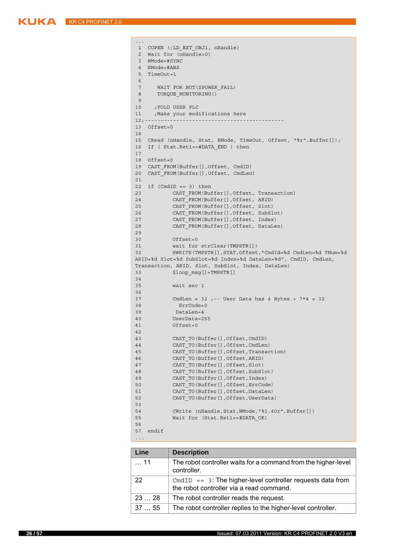
... 1 COPEN (:LD_EXT_OBJ1, nHandle) 2 Wait for (nHandle>0) 3 WMode=#SYNC 4 RMode=#ABS 5 TimeOut=1 6 7 WAIT FOR NOT($POWER_FAIL) 8 TORQUE_MONITORING() 9 10 ;FOLD USER PLC 11 ;Make your modifications here 12;-------------------------------------------- 13 Offset=0 14 15 CRead (nHandle, Stat, RMode, TimeOut, Offset, "%r",Buffer[]); 16 If ( Stat.Ret1==#DATA_END ) then 17 18 Offset=0 19 CAST_FROM(Buffer[],Offset, CmdID) 20 CAST_FROM(Buffer[],Offset, CmdLen) 21 22 if (CmdID == 3) then 23 CAST_FROM(Buffer[],Offset, Transaction) 24 CAST_FROM(Buffer[],Offset, ARID) 25 CAST_FROM(Buffer[],Offset, Slot) 26 CAST_FROM(Buffer[],Offset, SubSlot) 27 CAST_FROM(Buffer[],Offset, Index) 28 CAST_FROM(Buffer[],Offset, DataLen) 29 30 Offset=0 31 wait for strClear(TMPSTR[]) 32 SWRITE(TMPSTR[],STAT,Offset,"CmdId=%d CmdLen=%d TNum=%d ARID=%d Slot=%d SubSlot=%d Index=%d DataLen=%d", CmdID, CmdLen, Transaction, ARID, Slot, SubSlot, Index, DataLen) 33 $loop_msg[]=TMPSTR[] 34 35 wait sec 1 36 37 CmdLen = 32 ;-- User Data has 4 Bytes + 7*4 = 32 38 ErrCode=0 39 DataLen=4 40 UserData=255 41 Offset=0 42 43 CAST_TO(Buffer[],Offset,CmdID) 44 CAST_TO(Buffer[],Offset,CmdLen) 45 CAST_TO(Buffer[],Offset,Transaction) 46 CAST_TO(Buffer[],Offset,ARID) 47 CAST_TO(Buffer[],Offset,Slot) 48 CAST_TO(Buffer[],Offset,SubSlot) 49 CAST_TO(Buffer[],Offset,Index) 50 CAST_TO(Buffer[],Offset,ErrCode) 51 CAST_TO(Buffer[],Offset,DataLen) 52 CAST_TO(Buffer[],Offset,UserData) 53 54 CWrite (nHandle,Stat,WMode,"%1.40r",Buffer[]) 55 Wait for (Stat.Ret1==#DATA_OK) 56 57 endif ...
Line Description
… 11 The robot controller waits for a command from the higher-level controller.
22 CmdID == 3: The higher-level controller requests data from the robot controller via a read command.
23 … 28 The robot controller reads the request.
37 … 55 The robot controller replies to the higher-level controller.
Issued: 07.03.2011 Version: KR C4 PROFINET 2.0 V3 en

7 Programming
Detailed information about the following commands is contained in the documentation CREAD/CWRITE.
CHANNEL
CIOCTL
CAST_FROM; CAST_TO
COPEN; CCLOSE
CREAD; CWRITE
SREAD; SWRITE
37 / 57 Issued: 07.03.2011 Version: KR C4 PROFINET 2.0 V3 en

38 / 57
KR C4 PROFINET 2.0
Issued: 07.03.2011 Version: KR C4 PROFINET 2.0 V3 en
8 Diagnosis
8 Diagnosis
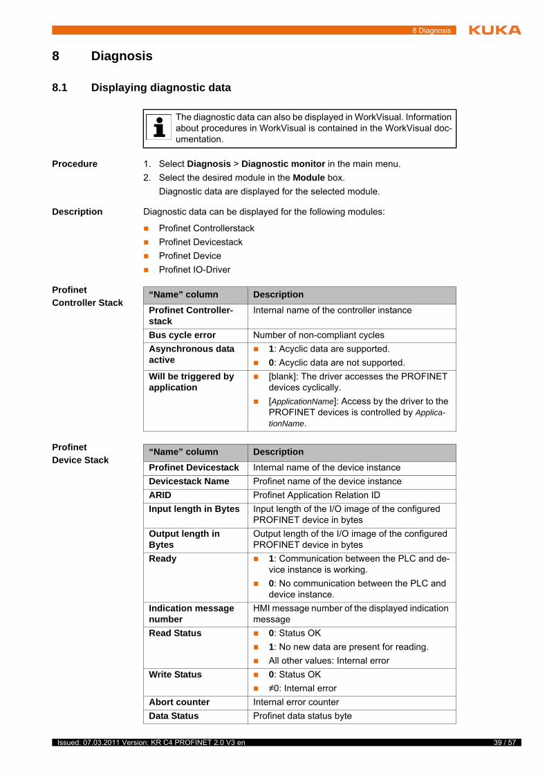
8.1 Displaying diagnostic data
Procedure 1. Select Diagnosis > Diagnostic monitor in the main menu.
2. Select the desired module in the Module box.
Diagnostic data are displayed for the selected module.
Description Diagnostic data can be displayed for the following modules:
Profinet Controllerstack
Profinet Devicestack
Profinet Device
Profinet IO-Driver
Profinet Controller Stack
Profinet Device Stack
The diagnostic data can also be displayed in WorkVisual. Information about procedures in WorkVisual is contained in the WorkVisual doc-umentation.
“Name” column Description
Profinet Controller-stack
Internal name of the controller instance
Bus cycle error Number of non-compliant cycles
Asynchronous data active
1: Acyclic data are supported.
0: Acyclic data are not supported.
Will be triggered by application
[blank]: The driver accesses the PROFINET devices cyclically.
[ApplicationName]: Access by the driver to the PROFINET devices is controlled by Applica-tionName.
“Name” column Description
Profinet Devicestack Internal name of the device instance
Devicestack Name Profinet name of the device instance
ARID Profinet Application Relation ID
Input length in Bytes Input length of the I/O image of the configured PROFINET device in bytes
Output length in Bytes
Output length of the I/O image of the configured PROFINET device in bytes
Ready 1: Communication between the PLC and de-vice instance is working.
0: No communication between the PLC and device instance.
Indication message number
HMI message number of the displayed indication message
Read Status 0: Status OK
1: No new data are present for reading.
All other values: Internal error
Write Status 0: Status OK
≠0: Internal error
Abort counter Internal error counter
Data Status Profinet data status byte
39 / 57 Issued: 07.03.2011 Version: KR C4 PROFINET 2.0 V3 en
40 / 57
KR C4 PROFINET 2.0
Profinet Device
Profinet IO Driver
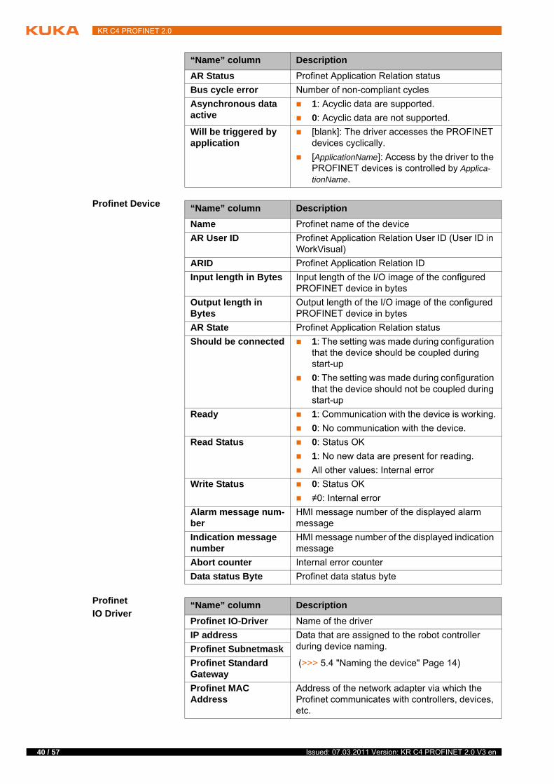
AR Status Profinet Application Relation status
Bus cycle error Number of non-compliant cycles
Asynchronous data active
1: Acyclic data are supported.
0: Acyclic data are not supported.
Will be triggered by application
[blank]: The driver accesses the PROFINET devices cyclically.
[ApplicationName]: Access by the driver to the PROFINET devices is controlled by Applica-tionName.
“Name” column Description
“Name” column Description
Name Profinet name of the device
AR User ID Profinet Application Relation User ID (User ID in WorkVisual)
ARID Profinet Application Relation ID
Input length in Bytes Input length of the I/O image of the configured PROFINET device in bytes
Output length in Bytes
Output length of the I/O image of the configured PROFINET device in bytes
AR State Profinet Application Relation status
Should be connected 1: The setting was made during configuration that the device should be coupled during start-up
0: The setting was made during configuration that the device should not be coupled during start-up
Ready 1: Communication with the device is working.
0: No communication with the device.
Read Status 0: Status OK
1: No new data are present for reading.
All other values: Internal error
Write Status 0: Status OK
≠0: Internal error
Alarm message num-ber
HMI message number of the displayed alarm message
Indication message number
HMI message number of the displayed indication message
Abort counter Internal error counter
Data status Byte Profinet data status byte
“Name” column Description
Profinet IO-Driver Name of the driver
IP address Data that are assigned to the robot controller during device naming.
(>>> 5.4 "Naming the device" Page 14)
Profinet Subnetmask
Profinet Standard Gateway
Profinet MAC Address
Address of the network adapter via which the Profinet communicates with controllers, devices, etc.
Issued: 07.03.2011 Version: KR C4 PROFINET 2.0 V3 en
8 Diagnosis
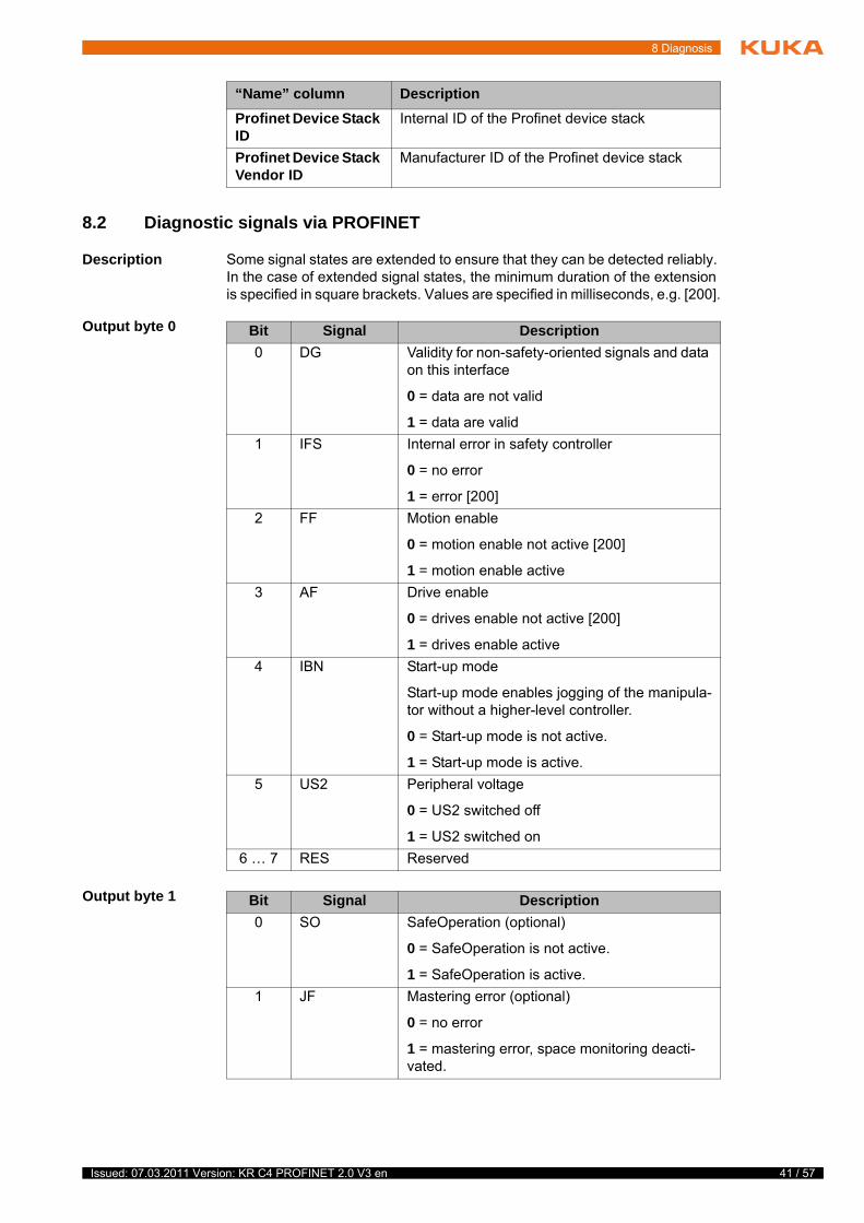
8.2 Diagnostic signals via PROFINET
Description Some signal states are extended to ensure that they can be detected reliably. In the case of extended signal states, the minimum duration of the extension is specified in square brackets. Values are specified in milliseconds, e.g. [200].
Output byte 0
Output byte 1
Profinet Device Stack ID
Internal ID of the Profinet device stack
Profinet Device Stack Vendor ID
Manufacturer ID of the Profinet device stack
“Name” column Description
Bit Signal Description
0 DG Validity for non-safety-oriented signals and data on this interface
0 = data are not valid
1 = data are valid
1 IFS Internal error in safety controller
0 = no error
1 = error [200]
2 FF Motion enable
0 = motion enable not active [200]
1 = motion enable active
3 AF Drive enable
0 = drives enable not active [200]
1 = drives enable active
4 IBN Start-up mode
Start-up mode enables jogging of the manipula-tor without a higher-level controller.
0 = Start-up mode is not active.
1 = Start-up mode is active.
5 US2 Peripheral voltage
0 = US2 switched off
1 = US2 switched on
6 … 7 RES Reserved
Bit Signal Description
0 SO SafeOperation (optional)
0 = SafeOperation is not active.
1 = SafeOperation is active.
1 JF Mastering error (optional)
0 = no error
1 = mastering error, space monitoring deacti-vated.
41 / 57 Issued: 07.03.2011 Version: KR C4 PROFINET 2.0 V3 en
42 / 57
KR C4 PROFINET 2.0
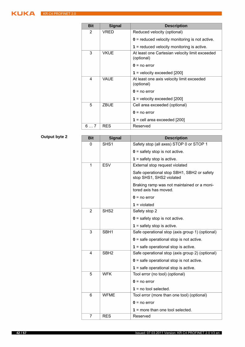
Output byte 2
2 VRED Reduced velocity (optional)
0 = reduced velocity monitoring is not active.
1 = reduced velocity monitoring is active.
3 VKUE At least one Cartesian velocity limit exceeded (optional)
0 = no error
1 = velocity exceeded [200]
4 VAUE At least one axis velocity limit exceeded (optional)
0 = no error
1 = velocity exceeded [200]
5 ZBUE Cell area exceeded (optional)
0 = no error
1 = cell area exceeded [200]
6 … 7 RES Reserved
Bit Signal Description
Bit Signal Description
0 SHS1 Safety stop (all axes) STOP 0 or STOP 1
0 = safety stop is not active.
1 = safety stop is active.
1 ESV External stop request violated
Safe operational stop SBH1, SBH2 or safety stop SHS1, SHS2 violated
Braking ramp was not maintained or a moni-tored axis has moved.
0 = no error
1 = violated
2 SHS2 Safety stop 2
0 = safety stop is not active.
1 = safety stop is active.
3 SBH1 Safe operational stop (axis group 1) (optional)
0 = safe operational stop is not active.
1 = safe operational stop is active.
4 SBH2 Safe operational stop (axis group 2) (optional)
0 = safe operational stop is not active.
1 = safe operational stop is active.
5 WFK Tool error (no tool) (optional)
0 = no error
1 = no tool selected.
6 WFME Tool error (more than one tool) (optional)
0 = no error
1 = more than one tool selected.
7 RES Reserved
Issued: 07.03.2011 Version: KR C4 PROFINET 2.0 V3 en
8 Diagnosis
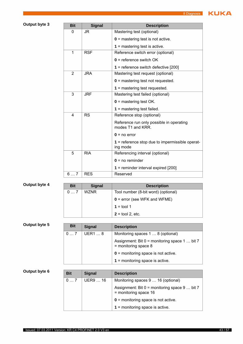
Output byte 3
Output byte 4
Output byte 5
Output byte 6
Bit Signal Description
0 JR Mastering test (optional)
0 = mastering test is not active.
1 = mastering test is active.
1 RSF Reference switch error (optional)
0 = reference switch OK
1 = reference switch defective [200]
2 JRA Mastering test request (optional)
0 = mastering test not requested.
1 = mastering test requested.
3 JRF Mastering test failed (optional)
0 = mastering test OK.
1 = mastering test failed.
4 RS Reference stop (optional)
Reference run only possible in operating modes T1 and KRR.
0 = no error
1 = reference stop due to impermissible operat-ing mode
5 RIA Referencing interval (optional)
0 = no reminder
1 = reminder interval expired [200]
6 … 7 RES Reserved
Bit Signal Description
0 … 7 WZNR Tool number (8-bit word) (optional)
0 = error (see WFK and WFME)
1 = tool 1
2 = tool 2, etc.
Bit Signal Description
0 … 7 UER1 … 8 Monitoring spaces 1 … 8 (optional)
Assignment: Bit 0 = monitoring space 1 … bit 7 = monitoring space 8
0 = monitoring space is not active.
1 = monitoring space is active.
Bit Signal Description
0 … 7 UER9 … 16 Monitoring spaces 9 … 16 (optional)
Assignment: Bit 0 = monitoring space 9 … bit 7 = monitoring space 16
0 = monitoring space is not active.
1 = monitoring space is active.
43 / 57 Issued: 07.03.2011 Version: KR C4 PROFINET 2.0 V3 en
44 / 57
KR C4 PROFINET 2.0
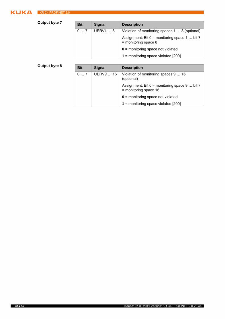
Output byte 7
Output byte 8
Bit Signal Description
0 … 7 UERV1 … 8 Violation of monitoring spaces 1 … 8 (optional)
Assignment: Bit 0 = monitoring space 1 … bit 7 = monitoring space 8
0 = monitoring space not violated
1 = monitoring space violated [200]
Bit Signal Description
0 … 7 UERV9 … 16 Violation of monitoring spaces 9 … 16 (optional)
Assignment: Bit 0 = monitoring space 9 … bit 7 = monitoring space 16
0 = monitoring space not violated
1 = monitoring space violated [200]
Issued: 07.03.2011 Version: KR C4 PROFINET 2.0 V3 en
9 Messages
9 Messages
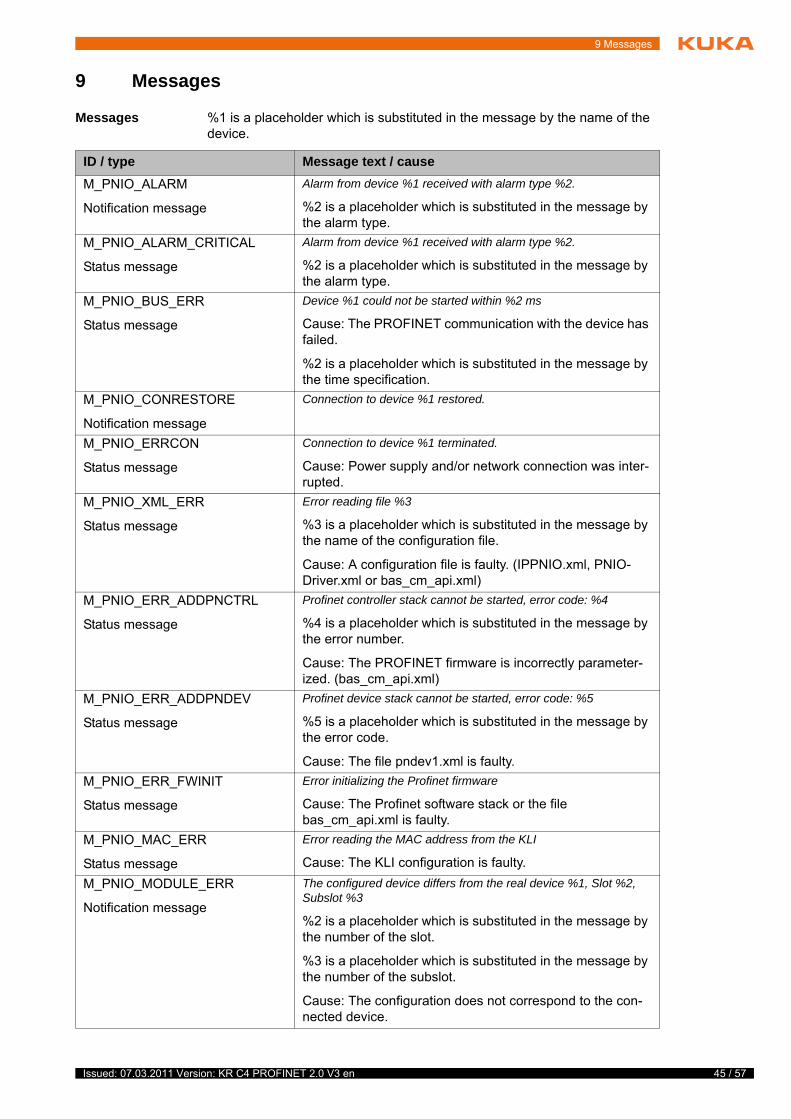
Messages %1 is a placeholder which is substituted in the message by the name of the device.
ID / type Message text / cause
M_PNIO_ALARM
Notification message
Alarm from device %1 received with alarm type %2.
%2 is a placeholder which is substituted in the message by the alarm type.
M_PNIO_ALARM_CRITICAL
Status message
Alarm from device %1 received with alarm type %2.
%2 is a placeholder which is substituted in the message by the alarm type.
M_PNIO_BUS_ERR
Status message
Device %1 could not be started within %2 ms
Cause: The PROFINET communication with the device has failed.
%2 is a placeholder which is substituted in the message by the time specification.
M_PNIO_CONRESTORE
Notification message
Connection to device %1 restored.
M_PNIO_ERRCON
Status message
Connection to device %1 terminated.
Cause: Power supply and/or network connection was inter-rupted.
M_PNIO_XML_ERR
Status message
Error reading file %3
%3 is a placeholder which is substituted in the message by the name of the configuration file.
Cause: A configuration file is faulty. (IPPNIO.xml, PNIO-Driver.xml or bas_cm_api.xml)
M_PNIO_ERR_ADDPNCTRL
Status message
Profinet controller stack cannot be started, error code: %4
%4 is a placeholder which is substituted in the message by the error number.
Cause: The PROFINET firmware is incorrectly parameter-ized. (bas_cm_api.xml)
M_PNIO_ERR_ADDPNDEV
Status message
Profinet device stack cannot be started, error code: %5
%5 is a placeholder which is substituted in the message by the error code.
Cause: The file pndev1.xml is faulty.
M_PNIO_ERR_FWINIT
Status message
Error initializing the Profinet firmware
Cause: The Profinet software stack or the file bas_cm_api.xml is faulty.
M_PNIO_MAC_ERR
Status message
Error reading the MAC address from the KLI
Cause: The KLI configuration is faulty.
M_PNIO_MODULE_ERR
Notification message
The configured device differs from the real device %1, Slot %2, Subslot %3
%2 is a placeholder which is substituted in the message by the number of the slot.
%3 is a placeholder which is substituted in the message by the number of the subslot.
Cause: The configuration does not correspond to the con-nected device.
45 / 57 Issued: 07.03.2011 Version: KR C4 PROFINET 2.0 V3 en
46 / 57
KR C4 PROFINET 2.0
Alarm types
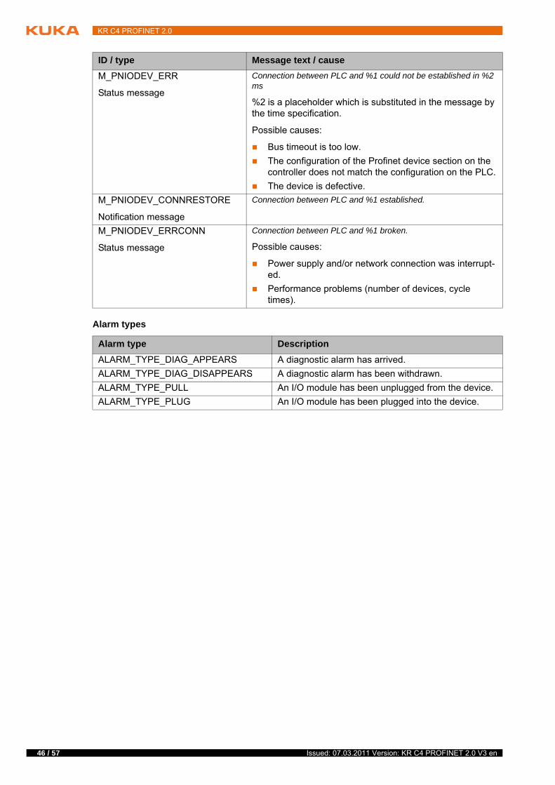
M_PNIODEV_ERR
Status message
Connection between PLC and %1 could not be established in %2 ms
%2 is a placeholder which is substituted in the message by the time specification.
Possible causes:
Bus timeout is too low.
The configuration of the Profinet device section on the controller does not match the configuration on the PLC.
The device is defective.
M_PNIODEV_CONNRESTORE
Notification message
Connection between PLC and %1 established.
M_PNIODEV_ERRCONN
Status message
Connection between PLC and %1 broken.
Possible causes:
Power supply and/or network connection was interrupt-ed.
Performance problems (number of devices, cycle times).
ID / type Message text / cause
Alarm type Description
ALARM_TYPE_DIAG_APPEARS A diagnostic alarm has arrived.
ALARM_TYPE_DIAG_DISAPPEARS A diagnostic alarm has been withdrawn.
ALARM_TYPE_PULL An I/O module has been unplugged from the device.
ALARM_TYPE_PLUG An I/O module has been plugged into the device.
Issued: 07.03.2011 Version: KR C4 PROFINET 2.0 V3 en
10 KUKA Service
10 KUKA Service
10.1 Requesting support
Introduction The KUKA Roboter GmbH documentation offers information on operation and provides assistance with troubleshooting. For further assistance, please con-tact your local KUKA subsidiary.
Information The following information is required for processing a support request:
Model and serial number of the robot
Model and serial number of the controller
Model and serial number of the linear unit (if applicable)
Version of the KUKA System Software
Optional software or modifications
Archive of the software
Application used
Any external axes used
Description of the problem, duration and frequency of the fault
10.2 KUKA Customer Support
Availability KUKA Customer Support is available in many countries. Please do not hesi-tate to contact us if you have any questions.
Argentina Ruben Costantini S.A. (Agency)
Luis Angel Huergo 13 20
Parque Industrial
2400 San Francisco (CBA)
Argentina
Tel. +54 3564 421033
Fax +54 3564 428877
Australia Headland Machinery Pty. Ltd.
Victoria (Head Office & Showroom)
95 Highbury Road
Burwood
Victoria 31 25
Australia
Tel. +61 3 9244-3500
Fax +61 3 9244-3501
www.headland.com.au
47 / 57 Issued: 07.03.2011 Version: KR C4 PROFINET 2.0 V3 en
48 / 57
KR C4 PROFINET 2.0
Belgium KUKA Automatisering + Robots N.V.
Centrum Zuid 1031
3530 Houthalen
Belgium
Tel. +32 11 516160
Fax +32 11 526794
www.kuka.be
Brazil KUKA Roboter do Brasil Ltda.
Avenida Franz Liszt, 80
Parque Novo Mundo
Jd. Guançã
CEP 02151 900 São Paulo
SP Brazil
Tel. +55 11 69844900
Fax +55 11 62017883
Chile Robotec S.A. (Agency)
Santiago de Chile
Chile
Tel. +56 2 331-5951
Fax +56 2 331-5952
www.robotec.cl
China KUKA Automation Equipment (Shanghai) Co., Ltd.
Songjiang Industrial Zone
No. 388 Minshen Road
201612 Shanghai
China
Tel. +86 21 6787-1808
Fax +86 21 6787-1805
www.kuka.cn
Germany KUKA Roboter GmbH
Zugspitzstr. 140
86165 Augsburg
Germany
Tel. +49 821 797-4000
Fax +49 821 797-1616
www.kuka-roboter.de
Issued: 07.03.2011 Version: KR C4 PROFINET 2.0 V3 en
10 KUKA Service
France KUKA Automatisme + Robotique SAS
Techvallée
6, Avenue du Parc
91140 Villebon S/Yvette
France
Tel. +33 1 6931660-0
Fax +33 1 6931660-1
www.kuka.fr
India KUKA Robotics, Private Limited
621 Galleria Towers
DLF Phase IV
122 002 Gurgaon
Haryana
Indien
Tel. +91 124 4148574
www.kuka.in
Italy KUKA Roboter Italia S.p.A.
Via Pavia 9/a - int.6
10098 Rivoli (TO)
Italy
Tel. +39 011 959-5013
Fax +39 011 959-5141
www.kuka.it
Japan KUKA Robotics Japan K.K.
Daiba Garden City Building 1F
2-3-5 Daiba, Minato-ku
Tokyo
135-0091
Japan
Tel. +81 3 6380-7311
Fax +81 3 6380-7312
Korea KUKA Robotics Korea Co. Ltd.
RIT Center 306, Gyeonggi Technopark
1271-11 Sa 3-dong, Sangnok-gu
Ansan City, Gyeonggi Do
426-901
Korea
Tel. +82 31 501-1451
Fax +82 31 501-1461
49 / 57 Issued: 07.03.2011 Version: KR C4 PROFINET 2.0 V3 en
50 / 57
KR C4 PROFINET 2.0
Malaysia KUKA Robot Automation Sdn Bhd
South East Asia Regional Office
No. 24, Jalan TPP 1/10
Taman Industri Puchong
47100 Puchong
Selangor
Malaysia
Tel. +60 3 8061-0613 or -0614
Fax +60 3 8061-7386
Mexico KUKA de Mexico S. de R.L. de C.V.
Rio San Joaquin #339, Local 5
Colonia Pensil Sur
C.P. 11490 Mexico D.F.
Mexico
Tel. +52 55 5203-8407
Fax +52 55 5203-8148
Norway KUKA Sveiseanlegg + Roboter
Bryggeveien 9
2821 Gjövik
Norway
Tel. +47 61 133422
Fax +47 61 186200
Austria KUKA Roboter Austria GmbH
Vertriebsbüro Österreich
Regensburger Strasse 9/1
4020 Linz
Austria
Tel. +43 732 784752
Fax +43 732 793880
www.kuka-roboter.at
Poland KUKA Roboter Austria GmbH
Spółka z ograniczoną odpowiedzialnością
Oddział w Polsce
Ul. Porcelanowa 10
40-246 Katowice
Poland
Tel. +48 327 30 32 13 or -14
Fax +48 327 30 32 26
Issued: 07.03.2011 Version: KR C4 PROFINET 2.0 V3 en
10 KUKA Service
Portugal KUKA Sistemas de Automatización S.A.
Rua do Alto da Guerra n° 50
Armazém 04
2910 011 Setúbal
Portugal
Tel. +351 265 729780
Fax +351 265 729782
Russia OOO KUKA Robotics Rus
Webnaja ul. 8A
107143 Moskau
Russia
Tel. +7 495 781-31-20
Fax +7 495 781-31-19
kuka-robotics.ru
Sweden KUKA Svetsanläggningar + Robotar AB
A. Odhners gata 15
421 30 Västra Frölunda
Sweden
Tel. +46 31 7266-200
Fax +46 31 7266-201
Switzerland KUKA Roboter Schweiz AG
Industriestr. 9
5432 Neuenhof
Switzerland
Tel. +41 44 74490-90
Fax +41 44 74490-91
www.kuka-roboter.ch
Spain KUKA Robots IBÉRICA, S.A.
Pol. Industrial
Torrent de la Pastera
Carrer del Bages s/n
08800 Vilanova i la Geltrú (Barcelona)
Spain
Tel. +34 93 8142-353
Fax +34 93 8142-950
www.kuka-e.com
51 / 57 Issued: 07.03.2011 Version: KR C4 PROFINET 2.0 V3 en
52 / 57
KR C4 PROFINET 2.0
South Africa Jendamark Automation LTD (Agency)
76a York Road
North End
6000 Port Elizabeth
South Africa
Tel. +27 41 391 4700
Fax +27 41 373 3869
www.jendamark.co.za
Taiwan KUKA Robot Automation Taiwan Co., Ltd.
No. 249 Pujong Road
Jungli City, Taoyuan County 320
Taiwan, R. O. C.
Tel. +886 3 4331988
Fax +886 3 4331948
www.kuka.com.tw
Thailand KUKA Robot Automation (M)SdnBhd
Thailand Office
c/o Maccall System Co. Ltd.
49/9-10 Soi Kingkaew 30 Kingkaew Road
Tt. Rachatheva, A. Bangpli
Samutprakarn
10540 Thailand
Tel. +66 2 7502737
Fax +66 2 6612355
www.kuka-roboter.de
Czech Republic KUKA Roboter Austria GmbH
Organisation Tschechien und Slowakei
Sezemická 2757/2
193 00 Praha
Horní Počernice
Czech Republic
Tel. +420 22 62 12 27 2
Fax +420 22 62 12 27 0
Hungary KUKA Robotics Hungaria Kft.
Fö út 140
2335 Taksony
Hungary
Tel. +36 24 501609
Fax +36 24 477031
Issued: 07.03.2011 Version: KR C4 PROFINET 2.0 V3 en
10 KUKA Service
USA KUKA Robotics Corp.
22500 Key Drive
Clinton Township
48036
Michigan
USA
Tel. +1 866 8735852
Fax +1 586 5692087
www.kukarobotics.com
UK KUKA Automation + Robotics
Hereward Rise
Halesowen
B62 8AN
UK
Tel. +44 121 585-0800
Fax +44 121 585-0900
53 / 57 Issued: 07.03.2011 Version: KR C4 PROFINET 2.0 V3 en

54 / 57
KR C4 PROFINET 2.0
Issued: 07.03.2011 Version: KR C4 PROFINET 2.0 V3 en
Index
Index
AAcyclic, communication 33
CCAST_FROM 37CAST_TO 37CCLOSE 37CHANNEL 37CIOCTL 37Communication, acyclic 33Configuration 13COPEN 37Coupling, device 31CREAD 37CWRITE 37
DDecoupling, device 31Diagnosis 39Diagnostic monitor (menu item) 39Diagnostic signals via PROFINET 41Documentation, industrial robot 5
GGSDML 6GSDML files, making available 13
IIndustrial Ethernet 6Installation 11Installation, PROFINET 11Introduction 5
KKUKA Customer Support 47
MMapping, inputs/outputs 21Messages 45
NNaming, device 14
OOperation 31
PPC WORX 6PLC 6Power management via PROFINET 29Product description 7Programming 33
SSafeOperation via PROFIsafe 26Safety 9Safety functions, PROFIsafe 22Safety instructions 5
Safety interface via PROFIsafe (optional) 22Service, KUKA Roboter 47SREAD 37Step 7 6Subnet 6Subnet mask 6Support request 47SWRITE 37System requirements 11
TTarget group 5Timeout, coupling 32Timeout, decoupling 32Trademarks 5
UUninstallation 12
WWarnings 5
55 / 57 Issued: 07.03.2011 Version: KR C4 PROFINET 2.0 V3 en

56 / 57
KR C4 PROFINET 2.0
Issued: 07.03.2011 Version: KR C4 PROFINET 2.0 V3 en

57 / 57 Issued: 07.03.2011 Version: KR C4 PROFINET 2.0 V3 en
KR C4 PROFINET 2.0