Embed Size (px)
Citation preview
SHORT-CIRCUIT CURRENT TeSTeD AccoRDING To DIN eN 61914KS
2020
Securing energy supplies is becoming increasingly important. Energy is generated by fossil energy sources and renewable energies. The last is generated by wind turbines in the form of wind energy. Wind turbines are installed on land (onshore) and in coastal regions of the oceans (offshore wind farms). Thus a failure does not always have to originate from the consumer or the feed, as the way from the generator to the consumer holds certain risks which have to be considered when securing the energy supply as well.
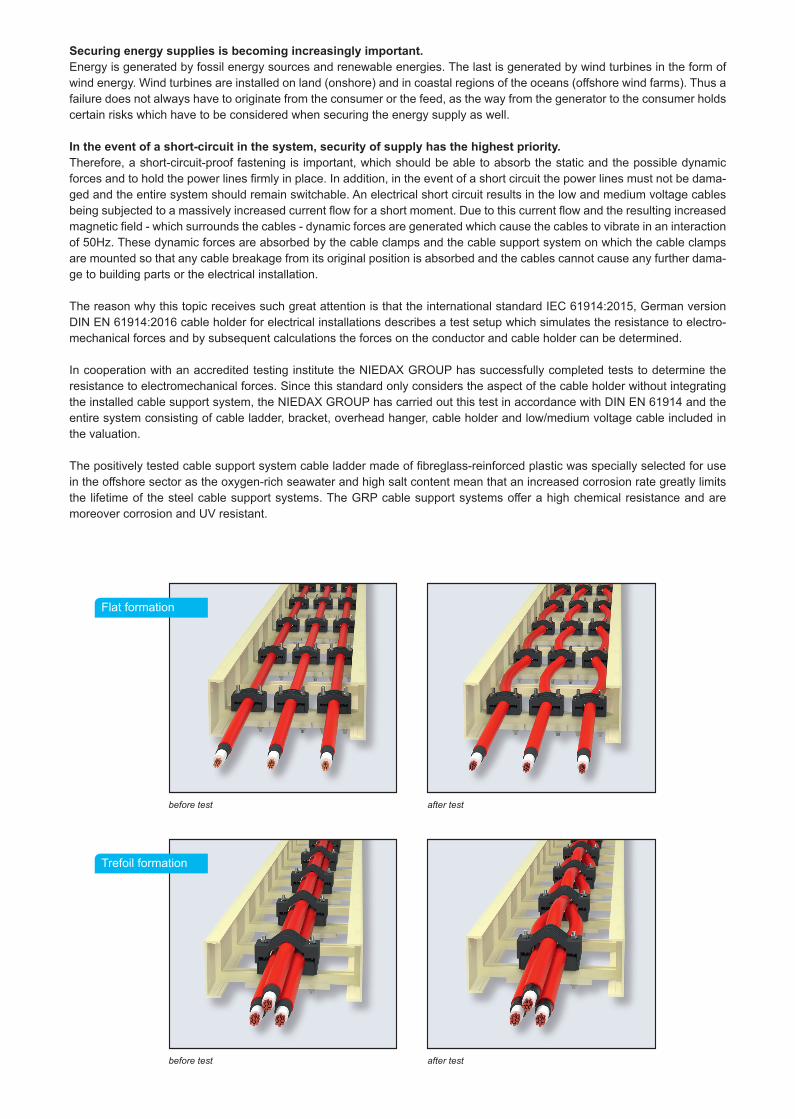
In the event of a short-circuit in the system, security of supply has the highest priority. Therefore, a short-circuit-proof fastening is important, which should be able to absorb the static and the possible dynamic forces and to hold the power lines firmly in place. In addition, in the event of a short circuit the power lines must not be dama-ged and the entire system should remain switchable. An electrical short circuit results in the low and medium voltage cables being subjected to a massively increased current flow for a short moment. Due to this current flow and the resulting increased magnetic field - which surrounds the cables - dynamic forces are generated which cause the cables to vibrate in an interaction of 50Hz. These dynamic forces are absorbed by the cable clamps and the cable support system on which the cable clamps are mounted so that any cable breakage from its original position is absorbed and the cables cannot cause any further dama-ge to building parts or the electrical installation.
The reason why this topic receives such great attention is that the international standard Iec 61914:2015, German version DIN eN 61914:2016 cable holder for electrical installations describes a test setup which simulates the resistance to electro-mechanical forces and by subsequent calculations the forces on the conductor and cable holder can be determined.
In cooperation with an accredited testing institute the NIEDAX GROUP has successfully completed tests to determine the resistance to electromechanical forces. Since this standard only considers the aspect of the cable holder without integrating the installed cable support system, the NIeDAX GRoUP has carried out this test in accordance with DIN eN 61914 and the entire system consisting of cable ladder, bracket, overhead hanger, cable holder and low/medium voltage cable included in the valuation.
The positively tested cable support system cable ladder made of fibreglass-reinforced plastic was specially selected for use in the offshore sector as the oxygen-rich seawater and high salt content mean that an increased corrosion rate greatly limits the lifetime of the steel cable support systems. The GRP cable support systems offer a high chemical resistance and are moreover corrosion and UV resistant.
Flat formation
Trefoil formation
before test
before test
after test
after test
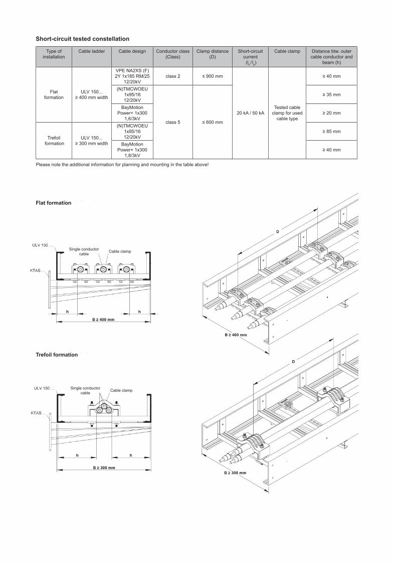
Short-circuit tested constellation
Type of installation
Cable ladder Cable design Conductor class (Class)
Clamp distance (D)
Short-circuit current (lk / lp)
Cable clamp Distance btw. outer cable conductor and
beam (h)
Flat formation
ULV 150... ≥ 400 mm width
VPE NA2XS (F) 2Y 1x185 RM/25
12/20kVclass 2 ≤ 900 mm
20 kA / 50 kATested cable
clamp for used cable type
≥ 40 mm
(N)TMCWOEU 1x95/16 12/20kV
class 5 ≤ 600 mm
≥ 35 mm
BayMotion Power+ 1x300
1,6/3kV≥ 20 mm
Trefoil formation
ULV 150... ≥ 300 mm width
(N)TMCWOEU 1x95/16 12/20kV
≥ 85 mm
BayMotion Power+ 1x300
1,8/3kV≥ 40 mm
Please note the additional information for planning and mounting in the table above!
Flat formation
Trefoil formation
Cable clamp
Cable clampSingle conductor cable
Single conductor cable
SHORT-CIRCUIT CURRENT
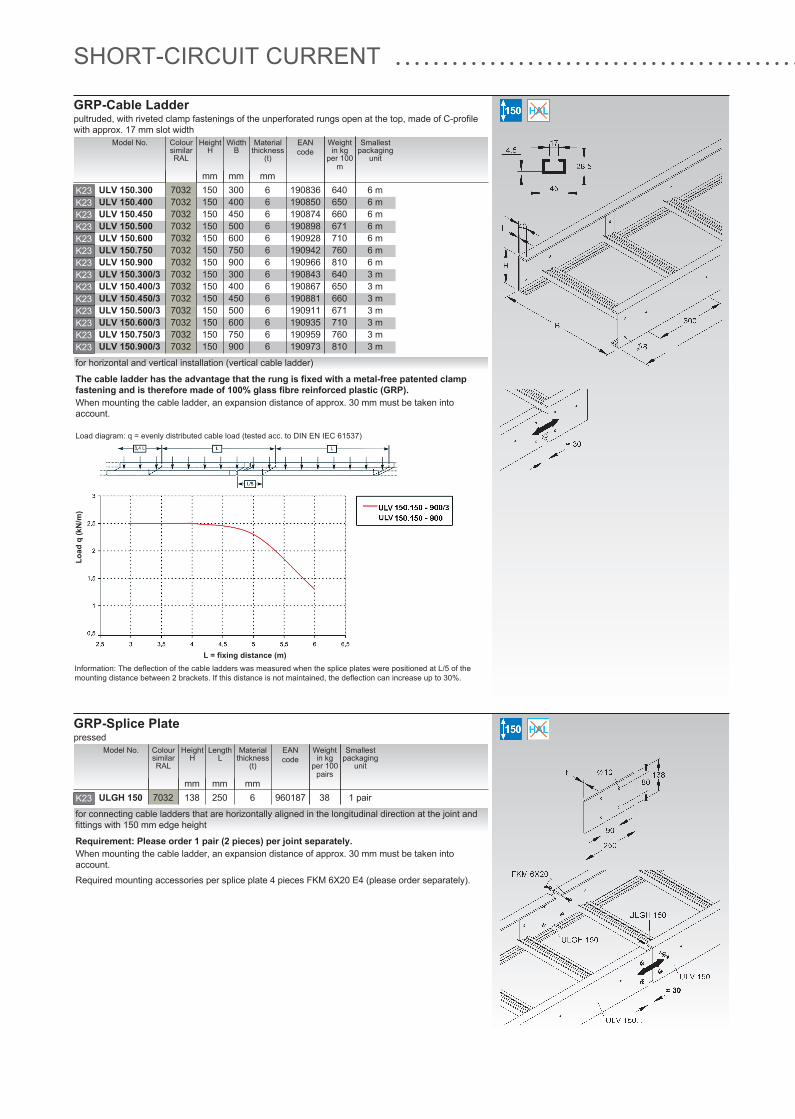
GRP-Cable Ladderpultruded, with riveted clamp fastenings of the unperforated rungs open at the top, made of C-profilewith approx. 17 mm slot width
L = fixing distance (m)
Load
q (k
N/m
)
Information: The deflection of the cable ladders was measured when the splice plates were positioned at L/5 of themounting distance between 2 brackets. If this distance is not maintained, the deflection can increase up to 30%.
The cable ladder has the advantage that the rung is fixed with a metal-free patented clampfastening and is therefore made of 100% glass fibre reinforced plastic (GRP).
for horizontal and vertical installation (vertical cable ladder)
Load diagram: q = evenly distributed cable load (tested acc. to DIN EN IEC 61537)
ULV 150.300 7032 150 300 6ULV 150.400 7032 150 400 6ULV 150.450 7032 150 450 6ULV 150.500 7032 150 500 6ULV 150.600 7032 150 600 6ULV 150.750 7032 150 750 6ULV 150.900 7032 150 900 6ULV 150.300/3 7032 150 300 6ULV 150.400/3 7032 150 400 6ULV 150.450/3 7032 150 450 6ULV 150.500/3 7032 150 500 6ULV 150.600/3 7032 150 600 6ULV 150.750/3 7032 150 750 6ULV 150.900/3 7032 150 900 6
K23K23K23K23K23K23K23K23K23K23K23K23K23K23
Model No. Colour similar RAL
Height H
WidthB
Materialthickness
(t)
mm mm mm
Smallestpackaging
unit
6 m6 m6 m6 m6 m6 m6 m3 m3 m3 m3 m3 m3 m3 m
EANcode
190836190850190874190898190928190942190966190843190867190881190911190935190959190973
Weightin kg
per 100
m
640650660671710760810640650660671710760810
When mounting the cable ladder, an expansion distance of approx. 30 mm must be taken intoaccount.
GRP-Splice Platepressed
Requirement: Please order 1 pair (2 pieces) per joint separately.
for connecting cable ladders that are horizontally aligned in the longitudinal direction at the joint andfittings with 150 mm edge height
Required mounting accessories per splice plate 4 pieces FKM 6X20 E4 (please order separately).
ULGH 150 7032 138 250 6K23
Model No. Colour similar RAL
Height H
LengthL
Materialthickness
(t)
mm mm mm
Smallestpackaging
unit
1 pair
EANcode
960187
Weightin kg
per 100
pairs
38
When mounting the cable ladder, an expansion distance of approx. 30 mm must be taken intoaccount.
SHORT-CIRCUIT CURRENT
GRP-Cable Ladderpultruded, with riveted clamp fastenings of the unperforated rungs open at the top, made of C-profilewith approx. 17 mm slot width
L = fixing distance (m)
Load
q (k
N/m
)
Information: The deflection of the cable ladders was measured when the splice plates were positioned at L/5 of themounting distance between 2 brackets. If this distance is not maintained, the deflection can increase up to 30%.
The cable ladder has the advantage that the rung is fixed with a metal-free patented clampfastening and is therefore made of 100% glass fibre reinforced plastic (GRP).
for horizontal and vertical installation (vertical cable ladder)
Load diagram: q = evenly distributed cable load (tested acc. to DIN EN IEC 61537)
ULV 150.300 7032 150 300 6ULV 150.400 7032 150 400 6ULV 150.450 7032 150 450 6ULV 150.500 7032 150 500 6ULV 150.600 7032 150 600 6ULV 150.750 7032 150 750 6ULV 150.900 7032 150 900 6ULV 150.300/3 7032 150 300 6ULV 150.400/3 7032 150 400 6ULV 150.450/3 7032 150 450 6ULV 150.500/3 7032 150 500 6ULV 150.600/3 7032 150 600 6ULV 150.750/3 7032 150 750 6ULV 150.900/3 7032 150 900 6
K23K23K23K23K23K23K23K23K23K23K23K23K23K23
Model No. Colour similar RAL
Height H
WidthB
Materialthickness
(t)
mm mm mm
Smallestpackaging
unit
6 m6 m6 m6 m6 m6 m6 m3 m3 m3 m3 m3 m3 m3 m
EANcode
190836190850190874190898190928190942190966190843190867190881190911190935190959190973
Weightin kg
per 100
m
640650660671710760810640650660671710760810
When mounting the cable ladder, an expansion distance of approx. 30 mm must be taken intoaccount.
GRP-Splice Platepressed
Requirement: Please order 1 pair (2 pieces) per joint separately.
for connecting cable ladders that are horizontally aligned in the longitudinal direction at the joint andfittings with 150 mm edge height
Required mounting accessories per splice plate 4 pieces FKM 6X20 E4 (please order separately).
ULGH 150 7032 138 250 6K23
Model No. Colour similar RAL
Height H
LengthL
Materialthickness
(t)
mm mm mm
Smallestpackaging
unit
1 pair
EANcode
960187
Weightin kg
per 100
pairs
38
When mounting the cable ladder, an expansion distance of approx. 30 mm must be taken intoaccount.
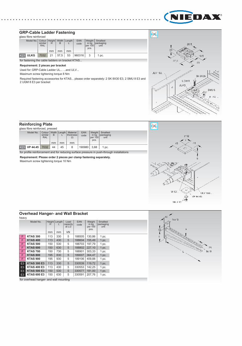
GRP-Cable Ladder Fasteningglass fibre reinforced
Requirement: 2 pieces per bracketfor fastening the cable ladders on bracket KTAS...
Used for: GRP-Cable Ladder UL... ...and ULV...
Required fastening accessories for KTAS... please order separately: 2 SK 8X30 E3, 2 SMU 8 E3 and2 UGM 8 E3 per bracket
ULKG
7032 21 57,5 53K23
Model No. Colour similar RAL
Height H
WidthB
LengthL
mm mm mm
Smallestpackaging
unit
1 pc.
EANcode
960316
Weightin kg
per 100
pcs.
3
Maximum screw tightening torque 8 Nm
Reinforcing Plateglass fibre reinforced, pressed
Requirement: Please order 2 pieces per clamp fastening separately.for profile reinforcement and for reducing surface pressure in push-through installations
VP 44.45
7032 44 45 8K23
Model No. Colour similar RAL
WidthB
LengthL
Materialthickness
(t)
mm mm mm
Smallestpackaging
unit
1 pc.
EANcode
190980
Weightin kg
per 100
pcs.
3,68
Maximum screw tightening torque 10 Nm
Overhead Hanger- and Wall Bracketheavy
for overhead hanger- and wall mounting
KTAS 300 113 330 5KTAS 400 113 430 5KTAS 500 150 530 5KTAS 600 150 630 5KTAS 700 150 730 5KTAS 800 195 830 5KTAS 900 195 930 5KTAS 300 E3 113 330 5KTAS 400 E3 113 430 5KTAS 500 E3 150 530 5KTAS 600 E3 150 630 5
FFFFFFF
E3E3E3E3
Model No. Height H
LengthL
Loadcapacity
at L/2
mm mm kN
Smallestpackaging
unit
1 pc.1 pc.1 pc.1 pc.1 pc.1 pc.1 pc.1 pc.1 pc.1 pc.1 pc.
EANcode
188505188604188703188802188901189007189106330539330553330577330591
Weightin kg
per 100
pcs.
130,86155,49197,79227,10303,33364,47409,88119,72142,25181,00207,76
Niedax GmbH & Co. KGAsbacher Straße 141D-53545 Linz/Rhein
Postfach 1286D-53541 Linz/Rhein
Tel: +49 (0) 2644/5606-0Fax: +49 (0) 2644/5606-13


![S právasi lni cOl omot = . = í; raj · ks ks ks ks ks ks ks ks 30294,0 CI 330,0 25,‹ 30,010 4233,00 4800,00 195,0 9 120,0 Q] (_) # (44) C) 21 6361,74 2“ 138,60 2' 42,00 21 189,00](https://img.pdfslide.net/doc/110x75/60abd032ab05c5114a4de9a2/s-prvasi-lni-col-omot-raj-ks-ks-ks-ks-ks-ks-ks-ks-302940-ci-3300-25a.jpg)