Embed Size (px)
Citation preview

1
KTT-E SeriesELECTRIC TABLE TOP TILTING KETTLE
INSTALLATION – OPERATION – MAINTENANCE
BLODGETT OVEN COMPANY
www.blodgett.com44 Lakeside Avenue, Burlington, Vermont 05401 USA Telephone (800) 331-5842, (802) 860-3700 Fax: (802) 864-0183
S00063 Rev A (5/04)
BLODGETT OVEN COMPANY
www.blodgett.com44 Lakeside Avenue, Burlington, Vermont 05401 USA
Manufacture Service Questions: 866-518-3977
PART NUMBER 170220 REV B (04/12)
G-SB SeriesGAS BOILER BASE STEAMER
INSTALLATION - OPERATION - MAINTENANCE

THIS MANUAL MUST BE RETAINED FOR FUTURE REFERENCE. READ, UNDERSTAND AND FOLLOW THE INSTRUCTIONS AND WARNINGS CONTAINED IN THIS MANUAL.
FOR YOUR SAFETYDO NOT STORE OR USE GASOLINE OR OTHER FLAMMABLE vAPORS AND LIqUIDS IN THE vICINITY OF THIS OR ANY OTHER APPLIANCE.
WARNING IMPROPER INSTALLATION, ADjUSTMENT, ALTERATION, SERvICE OR MAINTENANCE CAN CAUSE PROPERTY DAMAGE, INjURY OR DEATH. READ THE INSTALLATION, OPERATING AND MAINTENANCE INSTRUCTIONS THOROUGHLY BEFORE INSTALLING OR SERvICING THIS EqUIPMENT.
NOTIFY CARRIER OF DAMAGE AT ONCEIT IS THE RESPONSIBILITY OF THE CONSIGNEE TO INSPECT THE CONTAINER UPON RECEIPT OF SAME AND TO DETERMINE THE POSSIBILITY OF ANY DAMAGE, INCLUDING CONCEALED DAMAGE. WE SUGGEST THAT IF YOU ARE SUSPICIOUS OF DAMAGE TO MAkE A NOTATION ON THE DELIvERY RECEIPT. IT WILL BE THE RESPONSIBILITY OF THE CONSIGNEE TO FILE A CLAIM WITH THE CARRIER. WE RECOMMEND THAT YOU DO SO AT ONCE.
OM-G-SB 1
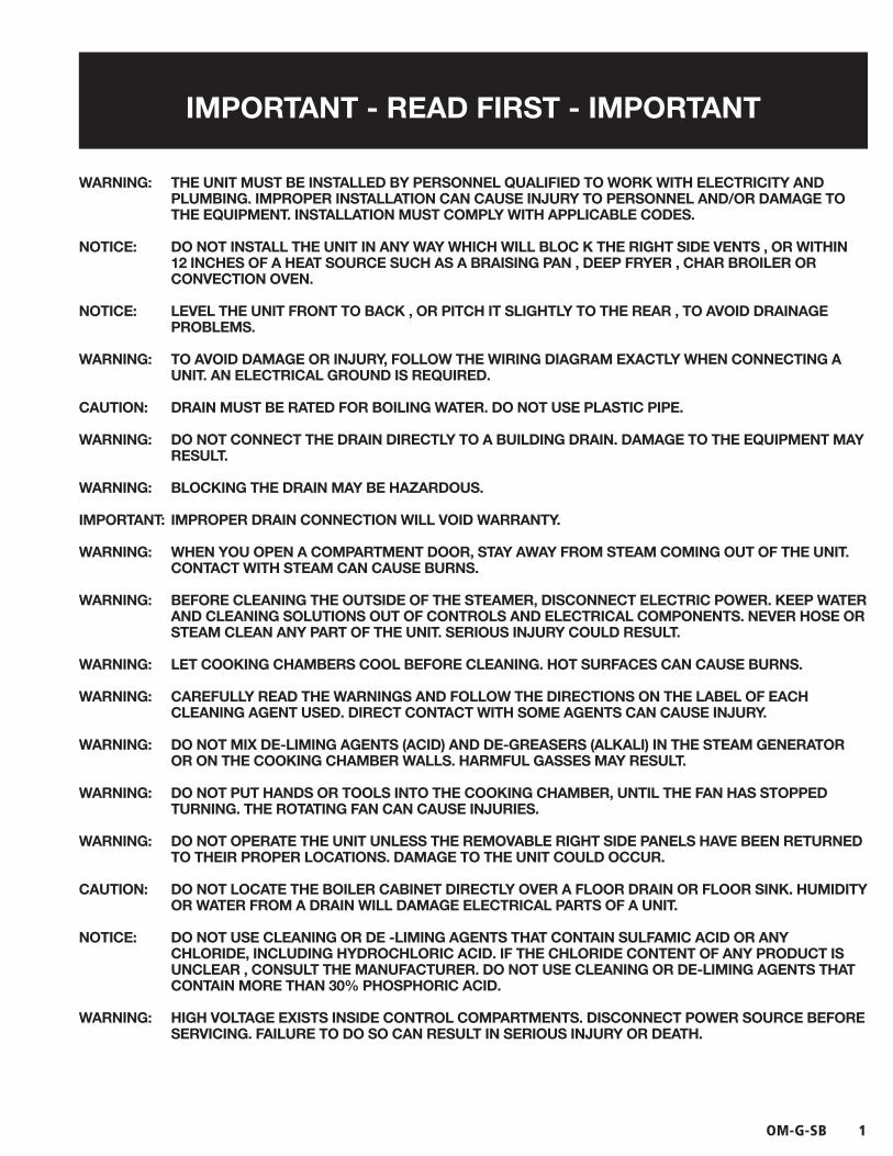
IMPORTANT - READ FIRST - IMPORTANT
WARNING: THE UNIT MUST BE INSTALLED BY PERSONNEL qUALIFIED TO WORk WITH ELECTRICITY AND PLUMBING. IMPROPER INSTALLATION CAN CAUSE INjURY TO PERSONNEL AND/OR DAMAGE TO THE EqUIPMENT. INSTALLATION MUST COMPLY WITH APPLICABLE CODES.
NOTICE: DO NOT INSTALL THE UNIT IN ANY WAY WHICH WILL BLOC k THE RIGHT SIDE vENTS , OR WITHIN 12 INCHES OF A HEAT SOURCE SUCH AS A BRAISING PAN , DEEP FRYER , CHAR BROILER OR CONvECTION OvEN.
NOTICE: LEvEL THE UNIT FRONT TO BACk , OR PITCH IT SLIGHTLY TO THE REAR , TO AvOID DRAINAGE PROBLEMS.
WARNING: TO AvOID DAMAGE OR INjURY, FOLLOW THE WIRING DIAGRAM EXACTLY WHEN CONNECTING A UNIT. AN ELECTRICAL GROUND IS REqUIRED.
CAUTION: DRAIN MUST BE RATED FOR BOILING WATER. DO NOT USE PLASTIC PIPE.
WARNING: DO NOT CONNECT THE DRAIN DIRECTLY TO A BUILDING DRAIN. DAMAGE TO THE EqUIPMENT MAY RESULT.
WARNING: BLOCkING THE DRAIN MAY BE HAZARDOUS.
IMPORTANT: IMPROPER DRAIN CONNECTION WILL vOID WARRANTY.
WARNING: WHEN YOU OPEN A COMPARTMENT DOOR, STAY AWAY FROM STEAM COMING OUT OF THE UNIT. CONTACT WITH STEAM CAN CAUSE BURNS.
WARNING: BEFORE CLEANING THE OUTSIDE OF THE STEAMER, DISCONNECT ELECTRIC POWER. kEEP WATER AND CLEANING SOLUTIONS OUT OF CONTROLS AND ELECTRICAL COMPONENTS. NEvER HOSE OR STEAM CLEAN ANY PART OF THE UNIT. SERIOUS INjURY COULD RESULT.
WARNING: LET COOkING CHAMBERS COOL BEFORE CLEANING. HOT SURFACES CAN CAUSE BURNS.
WARNING: CAREFULLY READ THE WARNINGS AND FOLLOW THE DIRECTIONS ON THE LABEL OF EACH CLEANING AGENT USED. DIRECT CONTACT WITH SOME AGENTS CAN CAUSE INjURY.
WARNING: DO NOT MIX DE-LIMING AGENTS (ACID) AND DE-GREASERS (ALkALI) IN THE STEAM GENERATOR OR ON THE COOkING CHAMBER WALLS. HARMFUL GASSES MAY RESULT.
WARNING: DO NOT PUT HANDS OR TOOLS INTO THE COOkING CHAMBER, UNTIL THE FAN HAS STOPPED TURNING. THE ROTATING FAN CAN CAUSE INjURIES.
WARNING: DO NOT OPERATE THE UNIT UNLESS THE REMOvABLE RIGHT SIDE PANELS HAvE BEEN RETURNED TO THEIR PROPER LOCATIONS. DAMAGE TO THE UNIT COULD OCCUR.
CAUTION: DO NOT LOCATE THE BOILER CABINET DIRECTLY OvER A FLOOR DRAIN OR FLOOR SINk. HUMIDITY OR WATER FROM A DRAIN WILL DAMAGE ELECTRICAL PARTS OF A UNIT.
NOTICE: DO NOT USE CLEANING OR DE -LIMING AGENTS THAT CONTAIN SULFAMIC ACID OR ANY CHLORIDE, INCLUDING HYDROCHLORIC ACID. IF THE CHLORIDE CONTENT OF ANY PRODUCT IS UNCLEAR , CONSULT THE MANUFACTURER. DO NOT USE CLEANING OR DE-LIMING AGENTS THAT CONTAIN MORE THAN 30% PHOSPHORIC ACID.
WARNING: HIGH vOLTAGE EXISTS INSIDE CONTROL COMPARTMENTS. DISCONNECT POWER SOURCE BEFORE SERvICING. FAILURE TO DO SO CAN RESULT IN SERIOUS INjURY OR DEATH.
2 OM-G-SB
IMPORTANT - READ FIRST - IMPORTANT
WARNING: DO NOT EXPOSE SkIN TO ESCAPING STEAM. SEvERE BURNS CAN RESULT.
CAUTION: MAkING ANY ELECTRICAL OR MECHANICAL CHANGE IN THE UNIT WITHOUT PRIOR WRITTEN APPROvAL FROM ENGINEERING WILL vOID ALL WARRANTIES.
WARNING: ALL POTENTIAL USERS OF THE EqUIPMENT SHOULD BE TRAINED IN SAFE AND CORRECT OPERATING PROCEDURES.
WARNING: DO NOT OPERATE THE UNIT UNLESS ALL REMOvABLE PANELS (RIGHT, LEFT, FRONT AND REAR) HAvE BEEN PROPERLY INSTALLED.
NOTICE: USE NO DE-GREASER THAT CONTAINS POTASSIUM HYDROXIDE OR SODIUM HYDROXIDE OR IS ALkALINE.
WARNING: USE OF ANY REPLACEMENT PARTS OTHER THAN THOSE SUPPLIED BY THE MANUFACTURER OR THEIR AUTHORIZED SERvICE AGENTS vOIDS ALL WARRANTIES AND CAN CAUSE BODILY INjURY TO THE OPERATOR AND DAMAGE THE EqUIPMENT. SERvICE PERFORMED BY OTHER THAN FACTORY AUTHORIZED PERSONNEL WILL vOID ALL WARRANTIES.
DANGER: HIGH vOLTAGE EXISTS IN CONTROL COMPARTMENTS. DISCONNECT FROM BRANCH CIRCUIT BEFORE SERvICING. FAILURE TO DO SO CAN RESULT IN SERIOUS INjURY OR DEATH.

OM-G-SB 3
Important Operator Warnings ..................................................... page 1-2References..................................................................................... page 3Equipment Description.................................................................. page 4Water Quality and Treatment ......................................................... page 5Installation .................................................................................. page 6-8Initial Start-Up........................................................................... page 9-10Operation ............................................................................... page 11-13Sequence of Operation ................................................................ page 14Cleaning.................................................................................. page 15-17Maintenance........................................................................... page 18-19Troubleshooting...................................................................... page 20-21Electrical Schematic ............................................................... page 31-32Service Log ................................................................................. page 33
UNDERWRITERS LABORATORIES, INC.333 Pfingsten RoadNorthbrook, Illinois 60062
KLENZADE SALES CENTERECOLAB, Inc.370 WabashaSt. Paul, Minnesota 55102800 328-3663 or 612 293-2233
NATIONAL FIRE PROTECTION ASSOCIATION60 Battery March ParkQuincy, Massachusetts 02269
NFPA/70 The National Electrical CodeNFPA/54 Installation of Gas Appliances & PipingNFPA/96 Ventilating Hoods
NSF INTERNATIONAL789 North Dixboro RoadP.O. Box 130140Ann Arbor, Michigan 48113-0140
AMERICAN NATIONAL STANDARDS INSTITUTE1403 Broadway, New York, New York 10018
Z21.30 Installation of Gas Appliances & PipingZ223.1 (latest edition) National Fuel Gas Code
Table of Contents
References
4 OM-G-SB
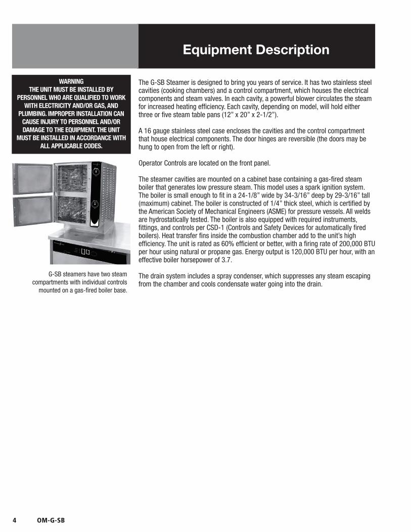
The G-SB Steamer is designed to bring you years of service. It has two stainless steelcavities (cooking chambers) and a control compartment, which houses the electricalcomponents and steam valves. In each cavity, a powerful blower circulates the steamfor increased heating efficiency. Each cavity, depending on model, will hold eitherthree or five steam table pans (12” x 20” x 2-1/2”).
A 16 gauge stainless steel case encloses the cavities and the control compartmentthat house electrical components. The door hinges are reversible (the doors may behung to open from the left or right).
Operator Controls are located on the front panel.
The steamer cavities are mounted on a cabinet base containing a gas-fired steamboiler that generates low pressure steam. This model uses a spark ignition system.The boiler is small enough to fit in a 24-1/8” wide by 34-3/16” deep by 29-3/16” tall(maximum) cabinet. The boiler is constructed of 1/4” thick steel, which is certified bythe American Society of Mechanical Engineers (ASME) for pressure vessels. All weldsare hydrostatically tested. The boiler is also equipped with required instruments,fittings, and controls per CSD-1 (Controls and Safety Devices for automatically firedboilers). Heat transfer fins inside the combustion chamber add to the unit’s highefficiency. The unit is rated as 60% efficient or better, with a firing rate of 200,000 BTUper hour using natural or propane gas. Energy output is 120,000 BTU per hour, with aneffective boiler horsepower of 3.7.
The drain system includes a spray condenser, which suppresses any steam escapingfrom the chamber and cools condensate water going into the drain.
Equipment Description
WARNINGTHE UNIT MUST BE INSTALLED BY
PERSONNEL WHO ARE QUALIFIED TO WORKWITH ELECTRICITY AND/OR GAS, AND
PLUMBING. IMPROPER INSTALLATION CANCAUSE INJURY TO PERSONNEL AND/ORDAMAGE TO THE EQUIPMENT. THE UNIT
MUST BE INSTALLED IN ACCORDANCE WITHALL APPLICABLE CODES.
G-SB steamers have two steamcompartments with individual controls
mounted on a gas-fired boiler base.

OM-G-SB 5
Water quality & Treatment
It is essential that the boiler be supplied with water that will not form scale at anunacceptable rate. The boiler was engineered to minimize scale, but its formationdepends on water hardness and how much the unit is used.
In some areas of the United States the water is low enough in mineral content to avoidscale build-up. However, most water supplies carry heavy loads of minerals. Thiswill form scale on the boiler, reduce its steam output, and possibly cause prematurecomponent failure.
Your water utility or local water quality dealer can tell you about the minerals in yourwater. The water going to the steam generator should have:
1. Between 1 and 30 ppm total dissolved solids (TDS)2. A pH (acidity rating) of 7.0 - 8.03. Total alkalinity less than 120 ppm4. Silica less than 13 ppm5. Chlorides less than 30 ppm6. Sulfates less than 40 ppm7. Chlorine less than 10 ppm
Please follow these simple precautions:
1. Do not rely on unproven water treatment equipment which is sold for scale prevention or scale removal. They frequently don’t work. The best way to prevent scale is to supply the purest possible water.
2. If your water contains scale-forming minerals, as most water does, use a well maintained water treatment system. Whether an exchangeable softener cartridge or a regenerating system is chosen, a regular exchange system is essential.
3. Installing a water meter on supply line to the steamer will provide an accurate gauge of water use, and will help determine when to exchange cartridges or regenerate the softener. Using treated water will provide longer generator life, higher steam capacity, and reduce maintenance requirements.
4. If you notice a slowdown in steam production, check the boiler for scale build-up. Heavy scale reduces the unit’s ability to boil water, and can even cause heating elements in the steam generator to overheat and burn out.
5. Pressure boilers are available with two separate water intakes:
one for the boiler (treated water) one for the spray condenser (untreated water).
The steam generator only uses 14 to 31% of a steamer’s water. Since water treatment systems are typically sized by total GPH (gallons per hour), the second intake could reduce treatment requirements by up to 80%, resulting in significant savings.
REDUCE SCALE PROBLEMS BY USING AND MAINTAINING A WATER SOFTENER
FOR YOUR STEAMER!

6 OM-G-SB
WHEN THE UNIT IS RECEIVED, IMMEDIATELY INSPECT IT FOR EXTERNAL OR INTERNAL DAMAGE. REPORT ANY DAMAGE TO THE FREIGHT CARRIER. After inspection, keep the unit in its shipping container until it is installed. It can be installed on combustible and non-combustible floors. Minimum clearances are:
Right Side 2 inchesLeft Side 4 inchesRear 6 inches
In order to service the unit properly, access with at least 24 inches clearance is needed on the right side.
Install the unit in a well-vented room so that there is an adequate air supply. Since products of combustion come out of its flue, the appliance must be located under a ventilation hood. Do not directly vent the flue.
Level the unit front to rear and left to right by adjusting its legs. Levelness may be checked by using a spirit level on top of the cabinet.
A free flow of air around the boiler promotes efficient operation. Items which might restrict air flow must be removed. After installation, do not obstruct the flue, or any front, side, rear or top vents. Similarly, keep the area directly around the appliance clear of combustible material.
Installation must conform with local codes, or in the absence of local codes, with the National Fuel Gas Code, ANSI Z223.1 (latest edition, including the following paragraph:
“The unit and its individual shut-off valve must be disconnected from the gas supply piping system during any pressure testing of that system at test pressures in excess of 1⁄2 PSI (3.45 kPA). The unit must be isolated from the gas piping system by closing its individual manual shut-off valve during any pressure testing of the gas supply piping system at test pressures equal to or less than 1⁄2 PSI (3.45 kPA).”
1. Gas Supply Connectiona. Connection to the gas supply can be completed with 1/2” NPT pipe
or approved equivalent. Although this is the diameter for immediate connection to the unit, gas supply piping must be large enough to provide volumes and pressure sufficient for 200,000 BTU per hour. Supply pressure must be at least 5.0” W.C. (14.0” W.C. maximum) for natural gas or 11.0 W.C. (14.0” W.C. maximum) for propane.
b. In Canada, the installation must conform to the Canada Gas Code, CAN
1-B149 (Installation Codes for Gas Burning Appliances and Equipment), and/or local codes.
c. After the unit has been connected to the gas supply, check piping joints for leaks. Do NOT use flame to check for leaks. A thick soap solution or other suitable leak detector should be used.
WARNINGMAKING ANY ELECTRICAL OR MECHANICAL
CHANGE IN THE UNIT WITHOUT PRIOR APPROVAL WILL VOID ALL WARRANTIES.
Installation
WARNINGTHE UNIT MUST BE INSTALLED BY
PERSONNEL WHO ARE QUALIFIED TO WORK WITH GAS, ELECTRICITY AND PLUMBING.
IMPROPER INSTALLATION CAN CAUSE INJURY TO PERSONNEL AND/OR DAMAGE
TO THE EQUIPMENT. THE UNIT MUST BE INSTALLED IN ACCORDANCE WITH
APPLICABLE CODES. THE UNIT MUST BE INSTALLED BY A LICENSED PLUMBER OR
GAS FITTER WHEN INSTALLED WITHIN THE COMMONWEALTH OF MASSACHUSETTS.

OM-G-SB 7
Installation
2. Electrical Supply Connection a. Power is supplied to cavity controls and blower from the boiler base,
and no other electrical connections are required.
b. The maximum electrical load is 4 AMP. You must provide 115 Volt Alternating Current, 60 Hz, 1PH, 15 AMP service. Local codes and/or the National Electrical Code should be followed (ANSI/NFPA-70-1987 - or latest edition). AN ELECTRICAL GROUND IS REQUIRED.
c. The electrical schematic is located in the electrical enclosure and in this manual. In Canada provide electrical service in accordance with the Canadian Electrical Code, CSA C22.1, Part 1 and/or local codes.
3. Water Supply Connection a. This Model features two separate water inlets – one for the steam boiler
(treated water), the other for the spray condenser (untreated water). The second intake will reduce treatment requirements resulting in significant savings.
b. Cold water should be supplied to a 3/8” NPT pipe connection for untreated water at the rear of the unit. A back siphonage device (check valve) must be installed, complying with local plumbing codes. The water pressure should be between 30 and 60 PSI (210 to 410 kPa). A pressure regulator is required above 60 PSI (410 kPa). A strainer screen at the connection is also recommended, to trap debris before it can enter the system.
c. The condenser spray uses 0.70 to 0.95 gallons of water per minute (2.6 to 3.6 liters per minute) at 30 to 60 PSI (210 and 410 kPa). The spray will only operate when a steamer cavity (cooking chamber) is in operation.
d. Water supply lines should be sized to provide for maximum water use (the total of the boiler and condenser spray) as shown in the following table:
Maximum Water Consumption-gal/hr (L/hr) Gas boiler only 12.9 (48.8)
Steamer Condenser Spray Only-gal/hr (L/hr) AT 40 PSI (280 kPa) 47.4 (180) AT 60 PSI (410 kPa) 57.0 (215)
4. Drain Connectiona. The drain connection is made at the rear of the unit, using a 1-1/4” NPT
pipe. Do NOT use plastic pipe — the piping must be able to withstand steam and hot water. Extend the drain piping to a nearby floor drain. Piping of 1 - 1/4” NPT (or 1 - 1/2” NPT) is acceptable for distances of six feet or less. If the distance to the drain is further than six feet, use 2” NPT piping.
b. Install the drain line with a constant downward pitch. Do not allow any water traps in the line. A trap can cause pressure to build up inside the cavity during steaming, which will make the door gasket leak. A vertical air gap must be maintained between the drain line and the building drain, unless otherwise specified by local plumbing codes.
WARNINGTHE UNIT MUST BE INSTALLED BY
PERSONNEL WHO ARE QUALIFIED TOWORK WITH ELECTRICITY AND PLUMBING.
IMPROPER INSTALLATION CAN CAUSEINJURY TO PERSONNEL AND/OR DAMAGE TO
THE EQUIPMENT. THE UNIT MUST BEINSTALLED IN ACCORDANCE WITH ALL
APPLICABLE CODES.
IMPORTANTIMPROPER DRAIN CONNECTION
WILL VOID WARRANTY.
Leave an air gap between the hose and the building drain, and don’t allow water traps in the line.
CAUTIONSHIPPING STRAPS ARE UNDER TENSION.THEY CAN SNAP BACK VIOLENTLY AND
CAUSE INJURY WHEN CUT.
CAUTIONMAKING ELECTRICAL OR MECHANICAL
CHANGES TO THE UNIT WITHOUT APPROVALFROM THE FOOD SERVICE ENGINEERINGDEPARTMENT WILL VOID WARRANTIES.
CAUTIONDO NOT LOCATE THE BOILER CABINETDIRECTLY OVER A FLOOR DRAIN ORFLOOR SINK. HUMIDITY OR WATER
WILL DAMAGE ELECTRICAL.
8 OM-G-SB
Installation
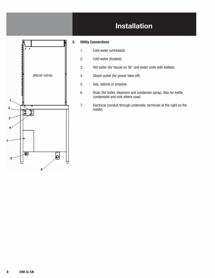
5. Utility Connections
1. Cold water (untreated).
2. Cold water (treated).
3. Hot water (for faucet on 36” and wider units with kettles).
4. Steam outlet (for power take-off).
5. Gas, natural or propane.
6. Drain (for boiler, steamers and condenser spray). Also for kettle condensate and sink where used.
7. Electrical (conduit through underside, terminals at the right on the inside).

OM-G-SB 9
Initial Start-Up
After the unit has been installed, test it to ensure that it is operating properly.
1. Remove literature and packing material from the interior and exterior of the unit.
2. Make certain the water supply is turned on.
3. Turn on electrical power to the unit.
4. Make sure the gas supply line is open, and turn on the gas valve.
Turn the knob on the gas valve to the “ON” position.
NOTE: The “trial for ignition” period is approximately 90 seconds after the on/off switch is turned to the “ON” position. (Refer to the Control Panel illustration in the Operation Section).
During initial start-up several trials may be necessary to remove air from the gas piping. Subsequent start-ups should only need about five seconds for the pilot to light. If the pilot burner does not light within the trial period, the ignition system will automatically stop gas flow to the pilot burner, and terminate the ignition trial. If this happens, turn the switch to “OFF” and then “ON” again, to repeat the trial for ignition.
5. Turn the on/off switch on the cabinet front panel to the “ON” position:• The amber light in the switch will come on • The boiler drain valve will close • The unit will fill with water
When the water level reaches the “mid” probe, the red RESET light will come on. Push the start switch.• The green light in the switch will come on • The RESET light will go out • The main burner will light
When the water level reaches the “hi” probe, the water supply to the boiler will shut off.
6. After about 15 minutes, the pressure on the gauge will rise. When the pressure reaches 9- 1/2 PSI, the main burner will turn off. Thereafter, as pressure decreases, the burner will automatically re-light to maintain the 9-1/2 PSI level. The pilot burner should stay lit, even though the main burner cycles on and off.
7. To shut the unit down, turn the on/off switch to OFF. When it has cooled to approximately 130ºF, the boiler will automatically drain.
The pilot is off when the on/off switch is OFF.
If the boiler functions as described above, it is ready for use. If it does not, contact your authorized Service Agent.
Operating Controls are located on the front of the cabinet base unit.
10 OM-G-SB
Initial Start-Up
8. When steam is available for the cavity, choose one of the following:
a. Set the timer to the desired time for timed steaming.
b. Turn the timer to the manual ON position for continuous steam.
NOTE: The door must be shut before steam will enter the cavity. If the door is opened when the timer is on, the flow of steam will stop.
c. Let the steamer sit idle until needed.
9. If the unit will not be used for an extended period, turn off power to the individual steamer compartments. Turn off power to the gas pressure boiler. Refer to the steam boiler operator manual, if necessary.
If the unit functions as described above, it is ready for use. If it does not, contact yourAuthorized Service Agent.
WARNINGSTAY AWAY FROM STEAM COMING OUT
FROM THE UNIT. STEAM CAN CAUSESEVERE BURNS.
OM-G-SB 11
Operation
A. Controls Operating controls are located on the front panel of the unit.
1. The on/off switch starts the unit or shuts it off.
2. The RESET indicator lights to show that the boiler has filled with water and that the main burners can ignite.
3. The start switch (momentary) lights the main burners. It also restarts the unit if electrical power is interrupted, or if a low water condition in the boiler disables the unit.
4. In addition to operating these controls, there are gas supply controls located on the gas valve.
When the control knob is “ON,” gas flows to the pilot, as well as to the main burners.
Timers are located on the front right side of the unit. There are two timers — one each for the upper and lower cavities.
The timer is used in two ways:
5. Turning the timer to any setting delivers steam to the cavity until the timer runs down to OFF. At that time a red LED switches on and a beeper sounds and the steam flow to the compartment stops.
6. When turned all the way to the ON position, the timer allows continuous steaming. A green LED is turned on, and the timer does not time down. Steam continues until the timer knob is turned to the OFF position.
WARNINGALL POTENTIAL USERS OF THE EQUIPMENT
SHOULD BE TRAINED IN SAFE AND CORRECT OPERATING PROCEDURES.
12 OM-G-SB
OFF
DONEON
TIMER
Operation
B. Operating Procedure
1. Turn on the unit’s water supply.
2. Turn on electrical power to the unit.
3. Turn on the gas supply to the unit, and turn on the gas valve. Turn the control knob on the gas valve to the “ON” position.
NOTE: The “ignition trial” period runs for approximately 90 seconds afterthe on/off switch is turned ON. This means that if the pilot light does notlight within the “trial” period, the ignition system will automatically stop thegas flow and terminate the ignition trial. If ignition is terminated, turn theswitch off and then “ON” again to repeat the trial. Normally, the pilot shouldlight within five seconds of turning on the unit.
a. Turn the on/off switch on the front of the cabinet to “ON.”1) The amber light will come on.2) The boiler drain valve will close and the unit will fill with water.3) When the water reaches the “mid” probe, the red RESET light will
come on.4) Press the start switch.5) The green light in the switch will come on, the RESET light will go off,
and the main burner will light.6) When the water level reaches the “hi” probe, the water supply to the
boiler will shut off.
b. After about 15 minutes, the pressure gauge will indicate that the pressure is rising. When it reaches 9-1/2 PSI, the main burner will shut off. Thereafter, the burner will periodically relight to maintain the pressure at 9-1/2 PSI. The pilot light should stay lit when the burner is off.
c. To shut down the unit, turn the on/off switch to OFF. The unit will drain automatically after it has cooled to about 130ºF. The unit turns off the pilot light when the on/off switch is turned to OFF.
4. Load food into pans so that it is in uniform layers. For best results, pans should be filled to about the same levels, and should be even on top.
5. Open the door and slide the pans onto the supports. If you will only be steaming one pan, put it in the middle rack position.
6. Close the door.
NOTE: The door must be closed before steam will enter the cavity. If thedoor is opened when the timer is on, the steam will stop.
WARNINGANY POTENTIAL USER OF THE EQUIPMENT
SHOULD BE TRAINED IN SAFE AND CORRECTOPERATING PROCEDURES.
WARNINGWHEN YOU OPEN THE DOOR, STAY AWAYFROM THE STEAM COMING OUT OF THEUNIT. THE STEAM CAN CAUSE BURNS.
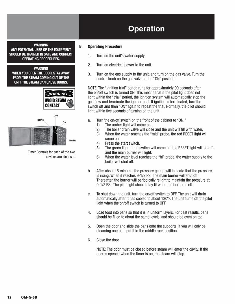
Timer Controls for each of the twocavities are identical.

OM-G-SB 13
Operation
7. Turn the timer to one of the following settings:
a. If you want to steam for a definite period of time, set the timer to that time. Steam will be delivered to the cavity for that time, and then stop. A buzzer and red LED will indicate that the timed cycle is complete. Steam flow stops.
b. If you want to steam continuously, turn the timer to the ON position. A green light will come on. Steam will be delivered to the cavity until the timer is returned to OFF.
8. Open the door.
9. Using a pad or oven mitt to protect your hands, remove the pans from the steamer.
10. To shut down the steamer, turn the Timer to the OFF position.

14 OM-G-SB
Sequence of Operation
CAUTIONWAIT AT LEAST 60 SECONDS BEFOREATTEMPTING TO RE-LIGHT THE MAIN
BURNER AFTER IT SHUTS OFF.
When electrical power is turned on to the unit, the following happens:• The drain valve closes• The water valve opens• The unit fills with water
As the boiler fills, the water is detected by two probes. The first of these is the “mid” probe, which activates the RESET light. The second (“hi” probe) is reached when the boiler is full, and shuts off the water supply. As the water supply drops below this probe, the water supply opens until it is again reached.
The gas valve has a step-opening feature. When the control calls for the main burner to light, the outlet pressure of the valve is maintained at a preset (non-adjustable) rate for several seconds, before full rated pressure is allowed to develop.
Once the main burner shuts down, step-opening gas valves need at least 60 seconds to reset. If an attempt to re-light the burner is made before these valves reset, it may bypass or shorten the length of the low pressure step, and could re-light the main burner under full flow rate.
A thermostatically-controlled air vent remains open while the boiler fills. As steam begins to develop, this vent will close. Some steam may escape from this vent before it is fully closed (at approximately 200ºF).
Once the pressure has reached 9-1/2 PSI, the main burner will be shut off by an operating pressure switch. Residual heat stored in the boiler’s heat exchanger can, however, cause the pressure to continue to build, even after the burner has shut down. This is especially true when the unit is heated for the first time.
If/when the pressure reaches 12 PSI, a relief valve will open to prevent pressure from increasing past 12 PSI. As pressure decreases, the main burner will automatically re-light to maintain 9-1/2 PSI.
Even if something causes the pressure to pass 12PSI, a high-limit safety switch will shut down the boiler electrically when it reaches 14-1/2 PSI. If this happens, the unit should not be re-started until the problem which caused the shut-down has been corrected.
As an additional safety measure, the unit is equipped with an A.S.M.E.-certified safety valve which will open to relieve excess pressure at 15 PSI. The ability of this valve to discharge steam pressure is greater than the boiler’s ability to generate steam.
When electrical power is turned off, the gas valve automatically shuts off flow to the main gas burner.
A thermostatic switch (mounted on the boiler shell) keeps the drain valve closed until the temperature drops to approximately 130ºF.
At that point, the thermostatic switch opens and water drains from the boiler. A vacuum breaker allows air to enter the boiler for this purpose.
CAUTIONESCAPING STEAM MAY CAUSE SEVER
BURNS. STAY AWAY FROM THERMOSTATIC AIR VENT AND PRESSURE RELIEF VALVES.
OM-G-SB 15
Steamer Compartment Cleaning
WARNINGDISCONNECT THE POWER SUPPLY BEFORECLEANING THE OUTSIDE OF THE STEAMER.
KEEP WATER AND CLEANING SOLUTIONS OUT OF CONTROLS AND ELECTRICAL
COMPONENTS. NEVER HOSE OR STEAM CLEAN ANY PART OF THE UNIT.
DON’T MIX DE-LIMING AGENTS (ACID) WITH DEGREASERS (ALKALI ) ANYWHERE IN THE UNIT.
AVOID CONTACT WITH ANY CLEANERS,DE-LIMING AGENT OR DE-GREASER AS
RECOMMENDED BY THE SUPPLIER. MANY ARE HARMFUL. READ THE WARNINGS AND
FOLLOW THE DIRECTIONS!
EVEN WHEN THE UNIT HAS BEEN SHUT OFF,DON’T PUT HANDS OR TOOLS INTO THE
COOKING CHAMBER UNTIL THE FAN HASSTOPPED TURNING.
DON’T OPERATE THE UNIT UNLESS REMOVABLE INTERIOR PARTITIONS
HAVE BEEN PUT BACK IN THEIR PROPER LOCATIONS.
DON’T USE ANY CLEANING OR DE-LIMINGAGENT THAT CONTAINS ANY SULFAMIC AGENT OR ANY CHLORIDE, INCLUDING
HYDROCHLORIC ACID (HCl). TO CHECK FOR CHLORIDE CONTENT SEE ANY MATERIAL SAFETY DATA SHEETS PROVIDED BY THE
CLEANING AGENT MANUFACTURER. DON’T USE ANY CLEANING OR DE-LIMING AGENT
THAT CONTAINS MORE THAN30% PHOSPHORIC ACID.
To keep your Steamer in proper working condition, clean the unit each day. Thisregular cleaning will reduce the effort required to clean the cavities.
A. Suggested Tools
1. Mild detergent2. Stainless steel exterior cleaner such as Spray Degreaser, Zepper®3. De-greaser, such as EncompasS®, Malone 34®, Puritan Puribrute®, or
Con-Lie®4. Cloth or sponge5. Plastic wool or a brush with soft bristles6. Spray bottle7. Measuring cup8. Nylon pad9. Towels10. Plastic disposable gloves
B. Procedure
1. Outsidea. Prepare a warm solution of mild detergent as instructed by the
supplier. Wet a cloth with this solution and wring it out. Use the moist cloth to clean the outside of the unit. Do not allow freely running liquid to touch the controls, the control panel, any electrical part, or any panel louver.
b. To remove material which may be stuck to the unit, use plastic wool, a fiber brush, or a plastic or rubber scraper with a detergent solution.
c. Stainless steel surfaces may be polished with a recognized stainless steel cleaner such as Zepper®.
2. InsideRemove the fan/baffle partition from inside the unit and place it into a utilitysink. Wash the cooking chamber(s) and fan/baffle partition with a warmsolution of mild detergent and water. If needed, use a de-greaser with aplastic scouring pad. Rinse parts thoroughly with clean water and replacefan/baffle partition. Make sure the drain holes at the back of each cavityare free of food particles or other debris.
IMPORTANTDO NOT USE ANY METAL MATERIAL (SUCH
AS METAL SPONGES) OR METAL IMPLEMENT (SUCH AS A SPOON, SCRAPER OR WIRE
BRUSH) THAT MIGHT SCRATCH STAINLESS STEEL SURFACES. SCRATCHES MAKE THE SURFACE HARD TO CLEAN AND PROVIDE PLACES FOR BACTERIA TO GROW. DO NOT
USE STEEL WOOL, WHICH MAY LEAVE PARTICLES IMBEDDED IN THE SURFACE,
WHICH COULD EVENTUALLY CAUSE CORROSION AND PITTING.

16 OM-G-SB
Boiler Cleaning
WARNINGWATER AND VALVES MAY BE VERY HOT,
AND MAY CAUSE BURNS. PROTECT HANDSFROM HOT SURFACES AND WATER.
Whenever the boiler is turned off and allowed to cool to about 130ºF, it drains automatically. This should be done every day to minimize scale buildup inside the boiler.
In addition to this draining, however, the following cleaning procedure should be followed using a regular schedule. This will prevent the accumulation of lime on the water level probes and interior surfaces of the boiler. The actual time between these scheduled cleanings depends on the water quality and hours of operation. Minimally, We recommend cleaning the boiler at least once each month.
A. Suggested Toolsa. 1/2” hardened square wrench extensionb. Pipe Joint compound (approved for 300ºF steam)c. Delimer Descalerd. Spray Degreasere. Nylon pad(s)
B. Procedure 1. Turn the boiler on/off switch to the OFF position.
2. Slowly open the manual drain valve to empty the boiler. The valve is located under the boiler.
3. Close the manual drain valve.
4. Turn off water supply to the boiler.
5. Allow the boiler to cool. This takes several hours, so it is recommended that you cool the boiler overnight.
6. Turn on/off switch to “ON” to close the automatic drain valve.
7. Using a 1/2” hardened square wrench extension, remove one of the 1” NPT pipe plugs from the front of the boiler.
8. Pour 32 ounces of de-limer into the boiler.
9. Replace the pipe plug. Use pipe joint compound, and tighten the plug securely.
10. Turn on water supply to allow water to fill the boiler.
11. When the reset light appears, press the START switch.
12. Allow boiler pressure to develop. Let it stand for approximately 15 minutes after pressure has built up. A badly limed unit may require more than 15 minutes.
The manual drain valve is located under the boiler.
WARNINGUSE SAFETY GLASSES AND RUBBER
GLOVES AS RECOMMENDED BY DE-LIMINGAGENT MANUFACTURER.
CAUTIONDO NOT USE A CLEANING OR DE-LIMINGAGENT THAT CONTAINS SULFAMIC ACID
OR ANY CHLORIDES, INCLUDING HYDROCHLORIC ACID (HCL). IF THE
CHLORIDE CONTENT OF ANY PRODUCT ISUNCLEAR, CONSULT THE MANUFACTURER.
OM-G-SB 17
Cleaning
13. Set steamer timers for 10 minutes.
14. When steamer timers sound, turn them to OFF and open the doors.
15. When the fans have stopped, remove fan baffle partitions using protective gloves, and rinse with clean water.
16. Completely wipe out steamer chambers using a degreaser and nylon pad, if necessary. Rinse thoroughly with clean water.
17. Replace fan baffle partitions.
18. Wait 10 minutes for the compartments to air dry, then close the steamer doors.
19. Turn the on/off switch OFF, and slowly open the manual drain valve.
20. When the boiler has drained completely, close the manual drain valve and turn the on/off switch to “ON” to fill the boiler with water.
21. After the RESET light comes on, press the start switch.
22. Allow boiler pressure to develop.
23. Set steamer timers for 10 minutes.
24. When steamer signal sounds, turn timers off.
25. If the boiler is not to be used, it may be turned off. It is ready for normal operation.
WARNINGSOLUTION AND VALVES WILL BE VERY HOT,AND MAY CAUSE BURNS. PROTECT HANDSFROM HOT SURFACES AND CONTINUE TO
USE PROTECTIVE GLOVES.

18 OM-G-SB
Steamer Maintenance
The Steamer is designed for minimum maintenance, and no user adjustments shouldbe necessary. Certain parts may need replacement after prolonged use. If there is aneed for service, only Authorized Service Representatives should do the work.
Periodic Inspection: The manufacturer recommends that service personnel checkthe unit thoroughly at least once a year. The inspection should include electrical wiresand connections. The inside of the control compartment should also be thoroughlycleaned.
Door Latch Adjustment: If steam or condensate is observed leaking from aroundthe door, take the following steps:
1. Check the condition of the door gasket. Replace it if it is cracked or split.
2. Inspect the cooking chamber drain for blockage.
3. Adjust the latch pin to allow for changes that might occur as the gasket ages.
a. Loosen the lock nut at the base of the latch pin, then turn the latch pin ¼ turn clockwise, and tighten the lock nut.
b. After adjustment, run the unit to test for further steam leakage.
c. If there is still leakage, repeat.
d. Continue adjusting the pin clockwise until the door fits tightly enough to prevent leakage.
e. If leakage is still present, repeat steps a. through c. until leakage stops.
A Maintenance and Service Log is provided at the back of this manual. Each timemaintenance is performed on the unit, enter the date the work was done, what wasdone, and who did it.
WARNINGBEFORE REPLACING ANY PART TURN OFF
THE ELECTRICAL POWER TO THE UNIT.DEATH OR INJURY COULD RESULT FROM
CONTACT WITH HIGH VOLTAGE.
OM-G-SB 19
Maintenance
Your boiler is designed to minimize maintenance, but certain parts may need tobe replaced after prolonged use. For the most part, no user adjustments should benecessary. If a need for service arises, only Authorized Representatives should performthe work.
Among the most common problems is the rapid build-up of scale in the boiler. To avoidthis, always supply water that has a low mineral content, which meets the standardsdescribed in the Water Quality section of this manual.
A. Periodic Inspection The unit should be inspected by a qualified service technician at least once each
year. The inspection should include electrical wires and connections, cleaning the inside of the control enclosure and pilot burner adjustment, if required.
At the back of this manual (with the information about our warranty) is a Main-tenance and Service Log. Each time maintenance is performed on the unit, enter the date on which it was done, what was done, and who did it. Keep this log with the warranty.
In addition to yearly inspections by a qualified service technician, a weekly check of the following will help prevent down time and ensure continued efficient operation.
1. Pressure gauge operation2. Proper water level (gauge)3. Strainer in water feed line (clear?)4. Air inlets for gas burner jets (clean?)5. Pilot burner flame (blue? Envelops sensor?)6. Drain piping (free running? No blockage?)
At least twice each month, check the safety valve to be sure it is working prop-erly. When pressure reaches five PSI on the gauge, lift the lever to vent steam, then release it, allowing it to snap back into place.
B. Component Replacement Boilers are easy to service. The design is simple, and controls are readily acces-
sible.
Before replacing any part, COMPLETELY SHUT OFF THE GAS AND ELECTRICAL POWER TO THE UNIT. When breaking (opening) a gas pipe connection, allow five minutes for gas to dissipate before proceeding.
When the pipes have been reconnected, check for leaks with a thick soap solu-tion or other suitable leak detector. Do not use flame to check for gas leaks.
WARNINGUSE ONLY MANUFACTURER-SUPPLIED PARTS.
USING SUBSTITUTE, UNAUTHORIZED OR“GENERIC” PARTS CAN CAUSE BODILY
INJURY TO THE OPERATOR AND DAMAGETHE EQUIPMENT.
WARNINGDO NOT EXPOSE SKIN TO ESCAPING STEAM.
SEVERE BURNS MAY RESULT.
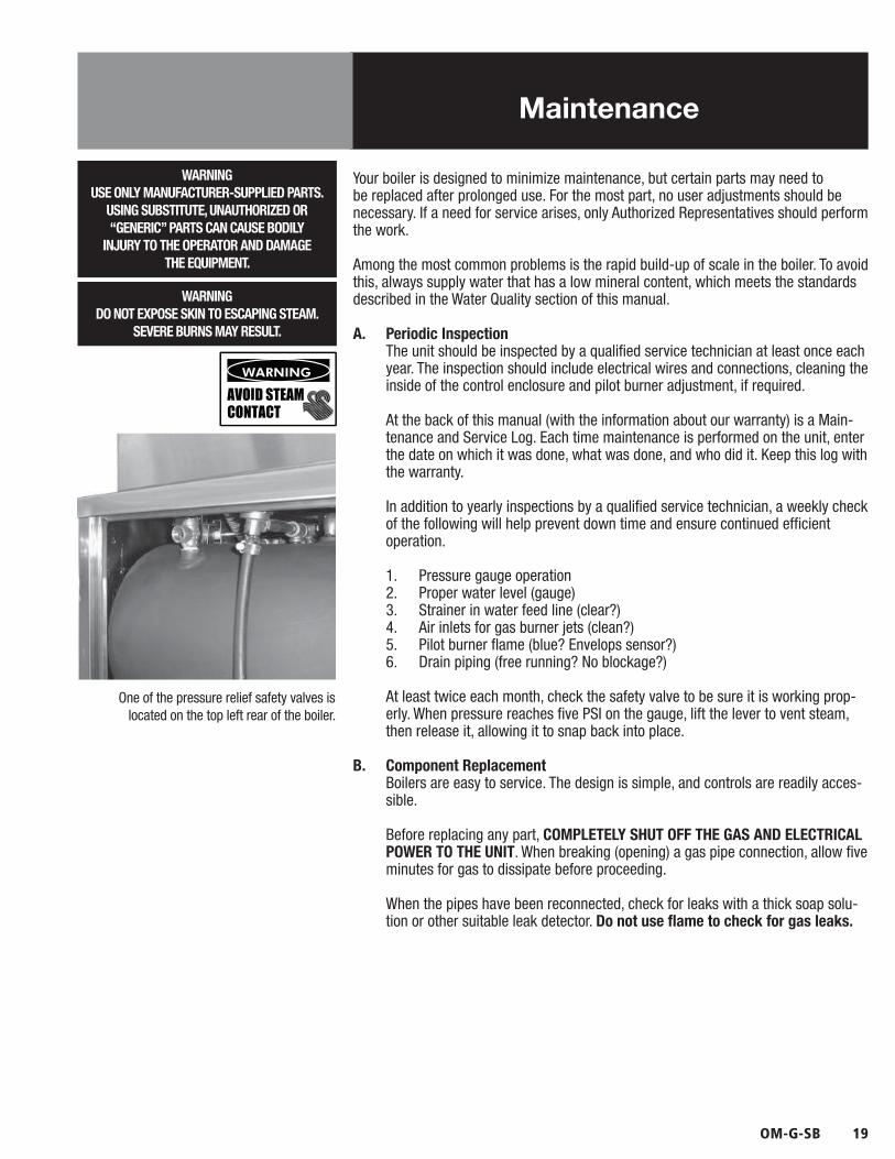
One of the pressure relief safety valves is located on the top left rear of the boiler.
20 OM-G-SB
Troubleshooting
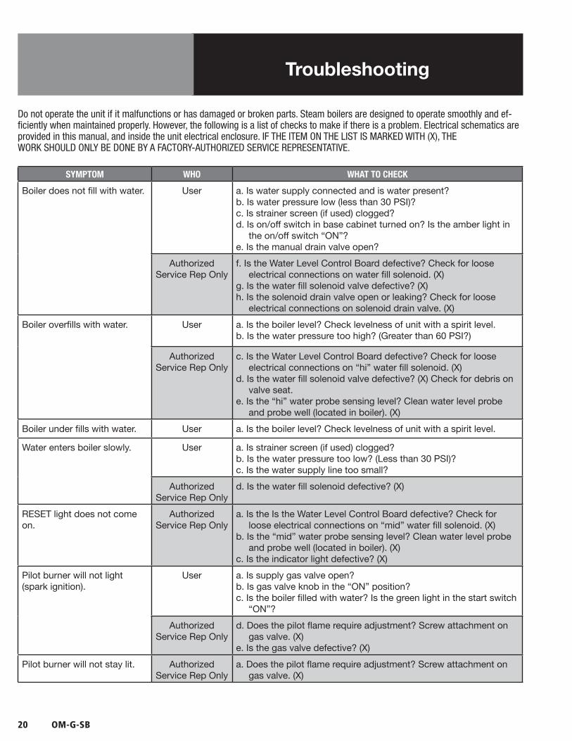
Do not operate the unit if it malfunctions or has damaged or broken parts. Steam boilers are designed to operate smoothly and ef-ficiently when maintained properly. However, the following is a list of checks to make if there is a problem. Electrical schematics are provided in this manual, and inside the unit electrical enclosure. IF THE ITEM ON THE LIST IS MARKED WITH (X), THEWORK SHOULD ONLY BE DONE BY A FACTORY-AUTHORIZED SERVICE REPRESENTATIVE.
SYMPTOM WHO WHAT TO CHECK
Boiler does not fill with water. User a. Is water supply connected and is water present?b. Is water pressure low (less than 30 PSI)?c. Is strainer screen (if used) clogged?d. Is on/off switch in base cabinet turned on? Is the amber light in
the on/off switch “ON”?e. Is the manual drain valve open?
Authorized Service Rep Only
f. Is the Water Level Control Board defective? Check for loose electrical connections on water fill solenoid. (X)
g. Is the water fill solenoid valve defective? (X)h. Is the solenoid drain valve open or leaking? Check for loose
electrical connections on solenoid drain valve. (X)Boiler overfills with water. User a. Is the boiler level? Check levelness of unit with a spirit level.
b. Is the water pressure too high? (Greater than 60 PSI?)
Authorized Service Rep Only
c. Is the Water Level Control Board defective? Check for loose electrical connections on “hi” water fill solenoid. (X)
d. Is the water fill solenoid valve defective? (X) Check for debris on valve seat.
e. Is the “hi” water probe sensing level? Clean water level probe and probe well (located in boiler). (X)
Boiler under fills with water. User a. Is the boiler level? Check levelness of unit with a spirit level.
Water enters boiler slowly. User a. Is strainer screen (if used) clogged?b. Is the water pressure too low? (Less than 30 PSI)?c. Is the water supply line too small?
Authorized Service Rep Only
d. Is the water fill solenoid defective? (X)
RESET light does not comeon.
Authorized Service Rep Only
a. Is the Is the Water Level Control Board defective? Check for loose electrical connections on “mid” water fill solenoid. (X)
b. Is the “mid” water probe sensing level? Clean water level probe and probe well (located in boiler). (X)
c. Is the indicator light defective? (X)Pilot burner will not light(spark ignition).
User a. Is supply gas valve open?b. Is gas valve knob in the “ON” position?c. Is the boiler filled with water? Is the green light in the start switch
“ON”?Authorized
Service Rep Onlyd. Does the pilot flame require adjustment? Screw attachment on
gas valve. (X)e. Is the gas valve defective? (X)
Pilot burner will not stay lit. Authorized Service Rep Only
a. Does the pilot flame require adjustment? Screw attachment on gas valve. (X)
OM-G-SB 21
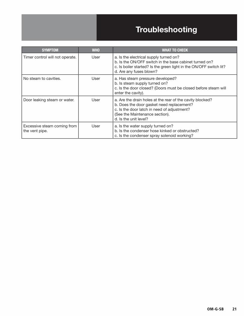
Troubleshooting
SYMPTOM WHO WHAT TO CHECK
Timer control will not operate. User a. Is the electrical supply turned on?b. Is the ON/OFF switch in the base cabinet turned on?c. Is boiler started? Is the green light in the ON/OFF switch lit?d. Are any fuses blown?
No steam to cavities. User a. Has steam pressure developed?b. Is steam supply turned on?c. Is the door closed? (Doors must be closed before steam willenter the cavity).
Door leaking steam or water. User a. Are the drain holes at the rear of the cavity blocked?b. Does the door gasket need replacement?c. Is the door latch in need of adjustment?(See the Maintenance section).d. Is the unit level?
Excessive steam coming from the vent pipe.
User a. Is the water supply turned on?b. Is the condenser hose kinked or obstructed?c. Is the condenser spray solenoid working?

22 OM-G-SB
Parts ListSteamer Cavity

OM-G-SB 23
Key Description Part #
1 UPPER CAVITY DRAIN HOSE 088847
2 MOTOR ASSEMBLY 096740
3 TIMER 096826
4 KNOB, TIMER 123100
5 PC BOARD, HY-PLUS LIGHT AND TIMER 130457
6 BRACKET, BOARD MTG 096888
7 STEAMER CONTROL BOARD 102222
8 CAPACITOR, 6 MFD - SG 096812
9 SHIELD, MOTOR DRIP 119844
10 NUT, ROTARY SHAFT SEAL 101145
11 NUT, KEPS 6-32 071289
12 HARNESS, UPPER CONTROL 130450
13 POST, PC BOARD MTG 099901
14 SCREW, 6-32 069777
15 JUMPER, VOLTAGE SELECT - SM & SG 100959
16 HARNESS, SPRAY VALVE - SG 130449
17 CABLE CLAMP 087958
18 NUT, 10-32 071256
19 NUT, 8-32 002632
Parts ListSteamer Cavity
Key Description Part #
20 TRANSFORMER, 75VA 110V - SG 121715
27 BUSHING - SG 012864
28 LOCK WASHER #8 - SG 12971
29 RELAY, DPDT 24VAC - SG 121733
30 SCREW, 8-32 X 3/8 - SG 069789
31 VALVE, SAFETY 143470
32 MANIFOLD FITTING 099249
33 GASKET 099250
34 NUT, 1/4-20 012940
35 TEE 013201
36 SOLENOID VALVE 113014
37 NIPPLE, 3/8 013202
38 CONNECTOR 054493
39 TUBE, UPPER 100551
40 ELBOW 042364
41 TEE 100553
42 TUBE, SUPPLY 100552
43 LOWER CAVITY DRAIN HOSE 088848
24 OM-G-SB
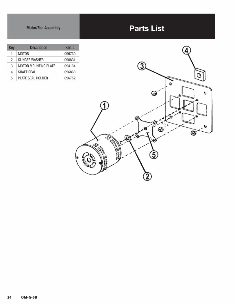
Key Description Part #
1 MOTOR 096739
2 SLINGER WASHER 096831
3 MOTOR MOUNTING PLATE 094134
4 SHAFT SEAL 096868
5 PLATE SEAL HOLDER 096752
Parts ListMotor/Fan Assembly

OM-G-SB 25
Key Description Part #
1 COVER, RIGHT SIDE (6-PAN) 143778
1 COVER, RIGHT SIDE (10-PAN) 159866
2 COVER, LEFT SIDE (6-PAN) 123184
2 COVER, LEFT SIDE (10-PAN) 159867
3 COVER ASSEMBLY, TOP 123182
4 SCREW, 10-32 X 3/8 TRUSS HEAD
004173
5 RETAINER, TOP 123156
6 SCREW, 8-32 X 3/8 SLOT-TED HEX HEAD
004173
7 DOOR HANDLE 070123
8 DOOR HINGE (6-PAN) 130868
8 DOOR HINGE (10-PAN) 125928
9 OUTER DOOR (6-PAN) 130858
9 OUTER DOOR (10-PAN) 125922
Parts ListSheet Metal & Doors
26 OM-G-SB
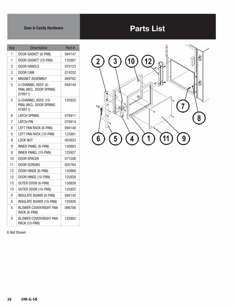
Key Description Part #
1 DOOR GASKET (6-PAN) 094147
1 DOOR GASKET (10-PAN) 125907
2 DOOR HANDLE 070123
3 DOOR CAM 074252
4 MAGNET ASSEMBLY 069762
5 U-CHANNEL ASSY. (6-PAN) (INCL. DOOR SPRING 078911)
094144
5 U-CHANNEL ASSY. (10-PAN) (INCL. DOOR SPRING 078911)
125925
6 LATCH SPRING 078911
7 LATCH PIN 078914
X LEFT PAN RACK (6-PAN) 094148
X LEFT PAN RACK (10-PAN) 125901
8 LOCK NUT 003823
9 INNER PANEL (6-PAN) 130863
9 INNER PANEL (10-PAN) 125927
10 DOOR SPACER 071206
11 DOOR SCREWS 005764
12 DOOR HINGE (6-PAN) 130868
12 DOOR HINGE (10-PAN) 125928
13 OUTER DOOR (6-PAN) 130858
13 OUTER DOOR (10-PAN) 125922
X INSULATE BOARD (6-PAN) 094142
X INSULATE BOARD (10-PAN) 125926
X BLOWER COVER/RIGHT PAN RACK (6-PAN)
096788
X BLOWER COVER/RIGHT PAN RACK (10-PAN)
125902
X-Not Shown
Parts ListDoor & Cavity Hardware
OM-G-SB 27
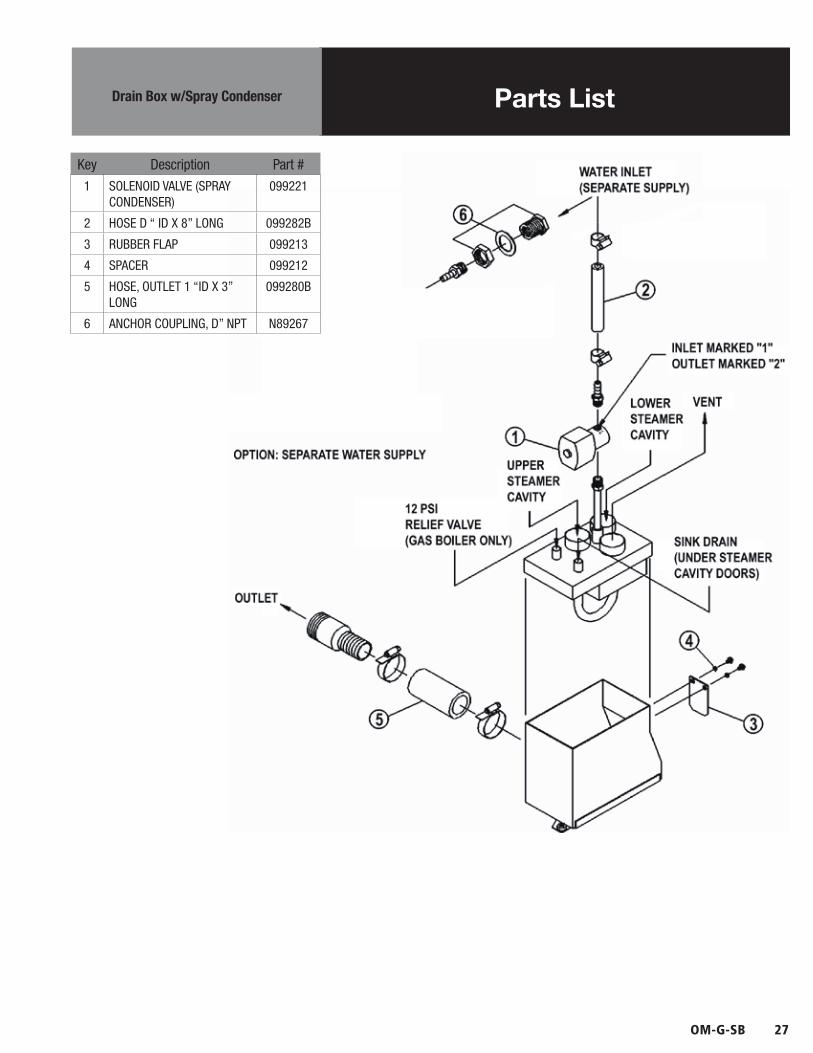
Key Description Part #
1 SOLENOID VALVE (SPRAY CONDENSER)
099221
2 HOSE D “ ID X 8” LONG 099282B
3 RUBBER FLAP 099213
4 SPACER 099212
5 HOSE, OUTLET 1 “ID X 3” LONG
099280B
6 ANCHOR COUPLING, D” NPT N89267
Parts ListDrain Box w/Spray Condenser
28 OM-G-SB
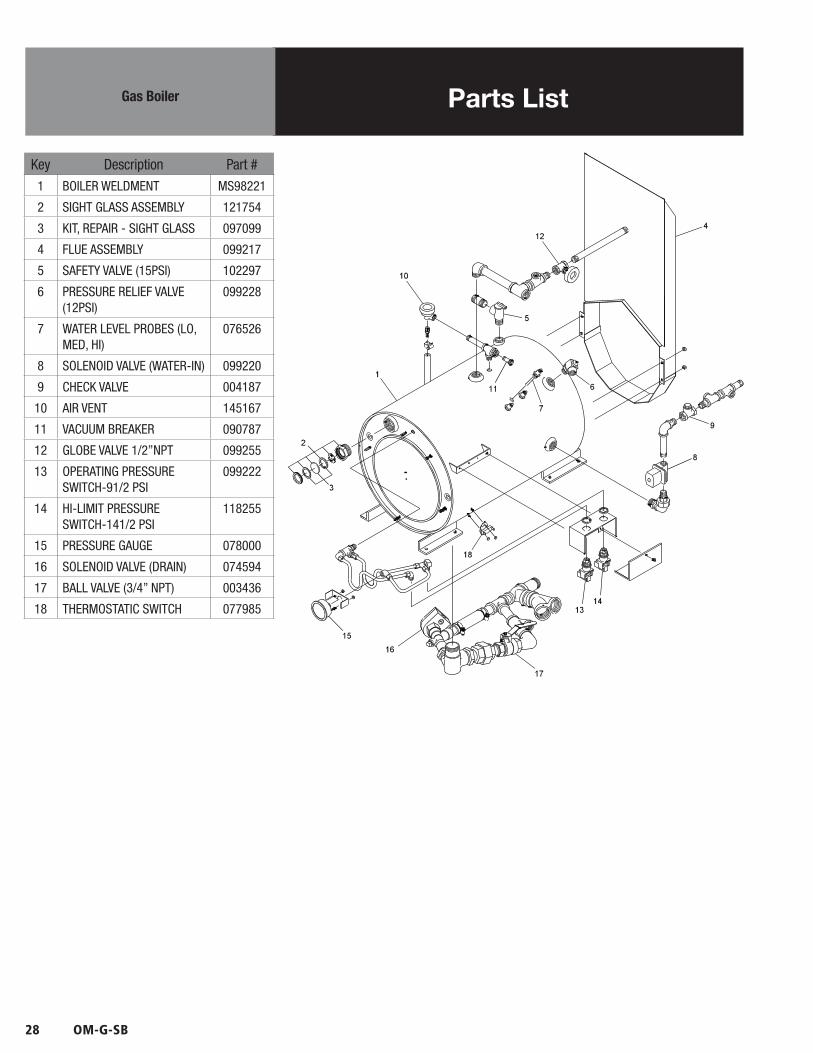
Key Description Part #
1 BOILER WELDMENT MS98221
2 SIGHT GLASS ASSEMBLY 121754
3 KIT, REPAIR - SIGHT GLASS 097099
4 FLUE ASSEMBLY 099217
5 SAFETY VALVE (15PSI) 102297
6 PRESSURE RELIEF VALVE (12PSI)
099228
7 WATER LEVEL PROBES (LO, MED, HI)
076526
8 SOLENOID VALVE (WATER-IN) 099220
9 CHECK VALVE 004187
10 AIR VENT 145167
11 VACUUM BREAKER 090787
12 GLOBE VALVE 1/2”NPT 099255
13 OPERATING PRESSURE SWITCH-91/2 PSI
099222
14 HI-LIMIT PRESSURE SWITCH-141/2 PSI
118255
15 PRESSURE GAUGE 078000
16 SOLENOID VALVE (DRAIN) 074594
17 BALL VALVE (3/4” NPT) 003436
18 THERMOSTATIC SWITCH 077985
Parts ListGas Boiler

OM-G-SB 29
Key Description Part #
1 BAFFLE PLATE 083076
2 PILOT BURNER MOUNTING BRACKET
102257
3 PILOT BURNER W/ SPARK IGNITER-SENSOR
102258
4 SHIELD FOR PILOT BURNER 102260
5 FLAME DEFLECTOR (SINGLE LOOP) HOLDER FOR #640
056965
7A MAIN BURNER ASSY 0-2000 FT. ELEV.(INCL. (29) GAS JETS W/ #54 DRILL DIA HOLE) FOR NATURAL GAS
047267
7A MAIN BURNER ASSY 0-2000 FT. ELEV.(INCL. (29) GAS JETS W/ #68 DRILL DIA HOLE) FOR PROPANE GAS
050491
8 GAS VALVE (SPARK IGNITION) FOR NATURAL GAS
101497
8 GAS VALVE (SPARK IGNITION) FOR PROPANE GAS
104391
9 SPARK IGNITION MODULE 085153
10 IGNITION CABLE 106495
11 BURNER MOUNTING BRACKET
050490
12 KIT, SPARK IGNITION MOD-ULE (INCLUDED BRACKET, MODULE AND CABLE)
137312
Parts ListBurner & Gas Valve
12
11

30 OM-G-SB
Key Description Part #
1 SWITCH “ON/OFF” 088876
2 SWITCH “START” (MOMEN-TARY)
099290
3 INDICATOR LIGHT “RESET” 099289
4 LIGHT, INDICATOR AMBER 116384
5 LIGHT, INDICATOR RED (2) 116383
6 TERMINAL BLOCK, 2-POLE 003887
- BUSHING SNAP 11/16” ID 012864
7 CIRCUIT BOARD SUPPORT 099292
8 WATER LEVEL CONTROL BOARD ASSEMBLY
116016
9 LUG, GROUND 14-6 AWG 119829
10 CIRCUIT BREAKER 119860
11 TRANSFORMER, 75VAC 121715
12 RELAY, DPDT 24VAC 30A 121733
13 WATER LEVEL CONTROL BOARD ASSEMBLY
122192
- HARNESS, ELECTRICAL BOX 130446
14 BRACKET, CIRCUIT BREAKER 137254
15 ELECTRONIC CABINET, WELDMENT
137257
Parts ListBoiler Electrical Controls
124
53
11 12 69 10 15
13 7
14
8
OM-G-SB 31
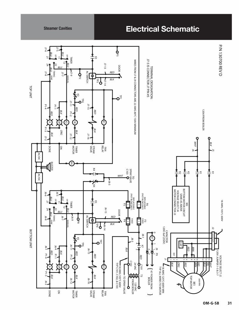
Electrical SchematicSteamer Cavities

32 OM-G-SB
Electrical SchematicBoiler
TO 120V AC
3A
L2
3
2
L2NC2
P2
S14 3
12
4 RED
2B LUE
RED1
J2HI
HI PRESSURER
2 1
12Y
FILL
R1
LOW WATER
2
GS2-A
READY LIGHT
S2-B
B
RESET
AR
S2-1S2-2
RESET SWITCH
TO SPARK
5 BLACK
9 BLACK
12 BLUE
K1
78
BROWN
ORANGE
8W HITE
7
6
10 RED
01
L1WHITE
GN
D
24V
SPA
RK MV
MV/
PVPV
GN
D B
URN
K1
NC
ORANGE3 N01L1
WHITE
BLACK
WHITETO T3@
STEAMER
120V
1
CB1
2
2BLUE
1RED
11WHITE
P1 J1
1
TSTAT DRAIN VALVE
1 22
T1
LO
14.5 PSI
OPERATING PRESSURE
GAS VALVE
7YELLOW
8BLACK
C
HL
12BLACK
10BLACK
9RED
C
PS
SW
H
C
GBLACK
YELLOW
BLUE
WHITE
4BLACK
6BROWN
5BLUE
3BROWN
PROBE
NC
NO
NC
PROBELO
G
FILL VALVE
PROBE
MID
HI
12
NO
BRO
WN
K1
C
PC2
LLCOPC1
G
4
NC1
NO2
C1
C2
H
LLCO
G
BROWN
WH
ITE
BLA
CK
@ STEAMER
21
SPRAY VALVE
FROM T2
COM
@ STEAMERTO K7 COIL
SINGLE WATER LEVEL CONTROL
DUAL WATER LEVEL CONTROL
HN GND
SPARK IGNITION MODULE
SWITCH CONTACT ARRANGEMENT
2 4
1
S1
3
A B
S2
1
2
3
4
CLOSES @ 170°
9.5 PSI
24VAC75VA
ON SWITCH
VIEWED FROM REAR
10A
HI LIMIT
MAIN
PILOT
GRN

OM-G-SB 33
Service Log
Model No: Purchased From:
Serial No: Location:
Date Purchased: Date Installed:
Purchase Order No: For Service Call:
Date Maintenance Performed Performed By

PART NUMBER 170184 REV B (04/11)
BLODGETT OVEN COMPANY
www.blodgett.com
44 Lakeside Avenue, Burlington, Vermont 05401 USATelephone: 866-518-3977