Embed Size (px)
Citation preview
Kuhnke Technical Data
The following page(s) are extracted from multi-page Kuhnke product catalogues or CDROMs and any page number shown is relevant to the original document. The PDF sheets here may have been combined to provide technical information about the specific product(s) you have selected. Hard copy product catalogues, and CDROMs have been published describing Kuhnke Pneumatics, Solenoids, Relays and Electronics; some divided into different books. A list of current publications is available on this web site or from our sales offices. Some may be available for download, but as substantially larger files. Contact Details
Kuhnke sales and service in the UK H. Kuhnke Ltd Unit 6 Focus 303 Focus Way, Walworth Business Park Andover Hampshire SP10 5NY United Kingdom Tel: +44 (0)1264 364194 Fax: +44 (0)1264 365991 Email: [email protected]
Important Note The information shown in these documents is for guidance only. No liability is accepted for any errors or omissions. The designer or user is solely responsible for the safe and proper application of the parts, assemblies or equipment described.
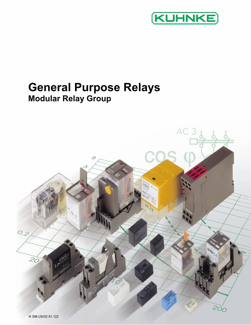
General Purpose RelaysModular Relay Group
R 398 US/02 91.122
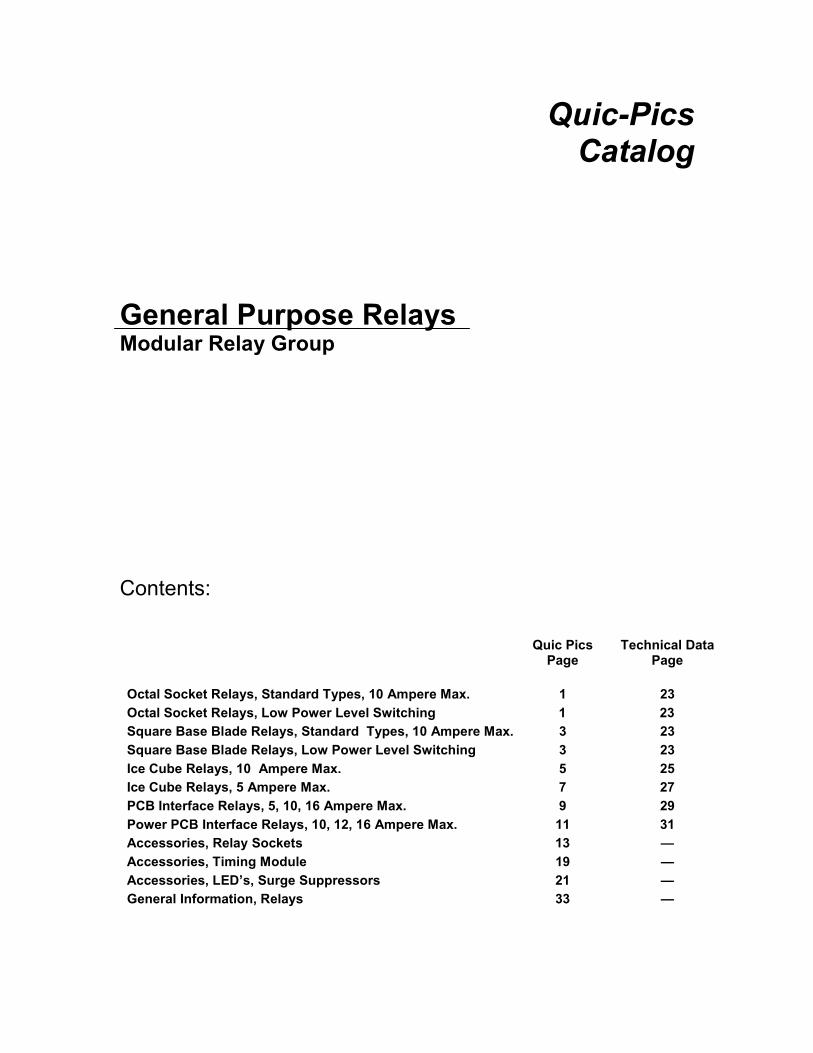
Quic-PicsCatalog
General Purpose RelaysModular Relay Group
Contents:
Quic PicsPage
Technical DataPage
Octal Socket Relays, Standard Types, 10 Ampere Max. 1 23Octal Socket Relays, Low Power Level Switching 1 23Square Base Blade Relays, Standard Types, 10 Ampere Max. 3 23Square Base Blade Relays, Low Power Level Switching 3 23Ice Cube Relays, 10 Ampere Max. 5 25Ice Cube Relays, 5 Ampere Max. 7 27PCB Interface Relays, 5, 10, 16 Ampere Max. 9 29Power PCB Interface Relays, 10, 12, 16 Ampere Max. 11 31Accessories, Relay Sockets 13 �—Accessories, Timing Module 19 �—Accessories, LED�’s, Surge Suppressors 21 �—General Information, Relays 33 �—
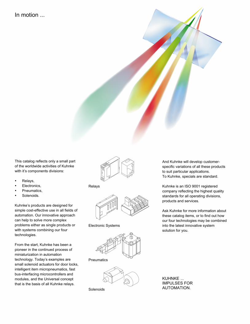
In motion ...
This catalog reflects only a small partof the worldwide activities of Kuhnkewith it�’s components divisions:
• Relays,• Electronics,• Pneumatics,• Solenoids.
Kuhnke�’s products are designed forsimple cost-effective use in all fields ofautomation. Our innovative approachcan help to solve more complexproblems either as single products orwith systems combining our fourtechnologies.
From the start, Kuhnke has been apioneer in the continued process ofminiaturization in automationtechnology. Today�’s examples aresmall solenoid actuators for door locks,intelligent item micropneumatics, fastbus-interfacing microcontrollers andmodules, and the Universal conceptthat is the basis of all Kuhnke relays.
Relays
Electronic Systems
Pneumatics
Solenoids
And Kuhnke will develop customer-specific variations of all these productsto suit particular applications.To Kuhnke, specials are standard.
Kuhnke is an ISO 9001 registeredcompany reflecting the highest qualitystandards for all operating divisions,products and services.
Ask Kuhnke for more information aboutthese catalog items, or to find out howour four technologies may be combinedinto the latest innovative systemsolution for you.
KUHNKE ...IMPULSES FORAUTOMATION.
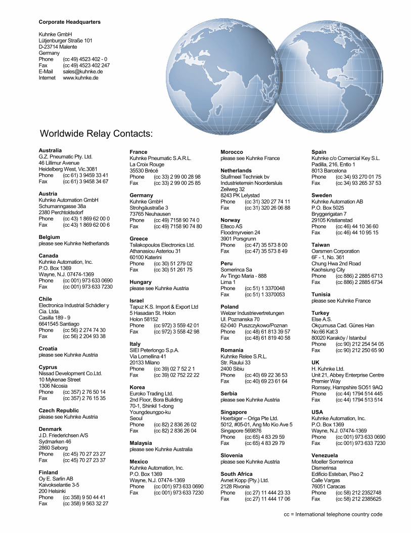
Corporate Headquarters
Kuhnke GmbHLütjenburger Straße 101D-23714 MalenteGermanyPhone (cc 49) 4523 402 - 0Fax (cc 49) 4523 402 247E-Mail [email protected] www.kuhnke.de
AustraliaG.Z. Pneumatic Pty. Ltd.46 Lillimur AvenueHeidelberg West, Vic.3081Phone (cc 61) 3 9459 33 41Fax (cc 61) 3 9458 34 67
AustriaKuhnke Automation GmbHSchumanngasse 38a2380 PerchtoldsdorfPhone (cc 43) 1 869 62 00 0Fax (cc 43) 1 869 62 00 6
Belgiumplease see Kuhnke Netherlands
CanadaKuhnke Automation, Inc.P.O. Box 1369Wayne, N.J. 07474-1369Phone (cc 001) 973 633 0690Fax (cc 001) 973 633 7230
ChileElectronica Industrial Schädler yCia. Ltda.Casilla 189 - 96641545 SantiagoPhone (cc 56) 2 274 74 30Fax (cc 56) 2 204 93 38
Croatiaplease see Kuhnke Austria
CyprusNissad Development Co.Ltd.10 Mykenae Street1306 NicosiaPhone (cc 357) 2 76 50 14Fax (cc 357) 2 76 15 35
Czech Republicplease see Kuhnke Austria
DenmarkJ.D. Friederichsen A/SSydmarken 462860 SøborgPhone (cc 45) 70 27 23 27Fax (cc 45) 70 27 23 37
FinlandOy E. Sarlin ABKaivokselantie 3-5200 HelsinkiPhone (cc 358) 9 50 44 41Fax (cc 358) 9 563 32 27
FranceKuhnke Pneumatic S.A.R.L.La Croix Rouge35530 BrécéPhone (cc 33) 2 99 00 28 98Fax (cc 33) 2 99 00 25 85
GermanyKuhnke GmbHStrohgäustraße 373765 NeuhausenPhone (cc 49) 7158 90 74 0Fax (cc 49) 7158 90 74 80
GreeceTsilakopoulos Electronics Ltd.Athanasiou Asteriou 3160100 KateriniPhone (cc 30) 51 279 02Fax (cc 30) 51 261 75
Hungaryplease see Kuhnke Austria
IsraelTapuz K.S. Import & Export Ltd5 Hasadan St. HolonHolon 58152Phone (cc 972) 3 559 42 01Fax (cc 972) 3 558 42 98
ItalySIEI Peterlongo S.p.A.Via Lomellina 4120133 MilanoPhone (cc 39) 02 7 52 2 1Fax (cc 39) 02 752 22 22
KoreaEuroko Trading Ltd.2nd Floor, Bora Building70-1, Shinkil 1-dongYoungdeungpo-kuSeoulPhone (cc 82) 2 836 26 02Fax (cc 82) 2 836 26 04
Malaysiaplease see Kuhnke Australia
MexicoKuhnke Automation, Inc.P.O. Box 1369Wayne, N.J. 07474-1369Phone (cc 001) 973 633 0690Fax (cc 001) 973 633 7230
Moroccoplease see Kuhnke France
NetherlandsStuifmeel Techniek bvIndustrieterrein NoordersluisZeilweg 328243 PK LelystadPhone (cc 31) 320 27 74 11Fax (cc 31) 320 26 06 88
NorwayElteco ASFloodmyrveien 243901 PorsgrunnPhone (cc 47) 35 573 8 00Fax (cc 47) 35 573 8 49
PeruSomerinca SaAv Tingo Maria - 888Lima 1Phone (cc 51) 1 3370048Fax (cc 51) 1 3370053
PolandWelzer IndustrievertretungenUl. Poznanska 7062-040 Puszczykowo/PoznanPhone (cc 48) 61 813 39 57Fax (cc 48) 61 819 40 58
RomaniaKuhnke Relee S.R.L.Str. Raului 332400 SibiuPhone (cc 40) 69 22 36 53Fax (cc 40) 69 23 61 64
Serbiaplease see Kuhnke Austria
SingaporeHoerbiger �– Origa Pte Ltd.5012, #05-01, Ang Mo Kio Ave 5Singapore 569876Phone (cc 65) 4 83 29 59Fax (cc 65) 4 83 29 79
Sloveniaplease see Kuhnke Austria
South AfricaAvnet Kopp (Pty.) Ltd.2128 RivoniaPhone (cc 27) 11 444 23 33Fax (cc 27) 11 444 17 06
SpainKuhnke c/o Comercial Key S.L.Padilla, 216, Entlo 18013 BarcelonaPhone (cc 34) 93 270 01 75Fax (cc 34) 93 265 37 53
SwedenKuhnke Automation ABP.O. Box 5025Bryggerigatan 729105 KristianstadPhone (cc 46) 44 10 36 60Fax (cc 46) 44 10 95 15
TaiwanOarsmen Corporation6F - 1, No. 361Chung Hwa 2nd RoadKaohsiung CityPhone (cc 886) 2 2885 6713Fax (cc 886) 2 2885 6734
Tunisiaplease see Kuhnke France
TurkeyElse A.S.Okçumusa Cad. Günes HanNo:66 Kat:380020 Karaköy / IstanbulPhone (cc 90) 212 254 54 05Fax (cc 90) 212 250 65 90
UKH. Kuhnke Ltd.Unit 21, Abbey Enterprise CentrePremier WayRomsey, Hampshire SO51 9AQPhone (cc 44) 1794 514 445Fax (cc 44) 1794 513 514
USAKuhnke Automation, Inc.P.O. Box 1369Wayne, N.J. 07474-1369Phone (cc 001) 973 633 0690Fax (cc 001) 973 633 7230
VenezuelaMoeller SomerincaDismerinsaEdificio Esteban, Piso 2Calle Vargas76051 CaracasPhone (cc 58) 212 2352748Fax (cc 58) 212 2385625
cc = International telephone country code
Worldwide Relay Contacts:
1 Kuhnke Automation Inc. 973-633-0690 Fax 973-633-7230
Type UF Universal Relays�™ Kuhnke Modular Relay Group
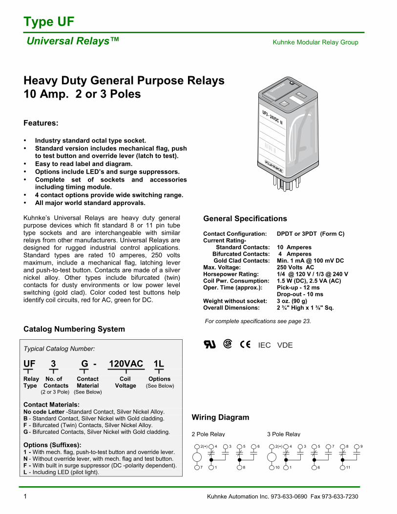
Heavy Duty General Purpose Relays10 Amp. 2 or 3 Poles
Features:
• Industry standard octal type socket.• Standard version includes mechanical flag, push
to test button and override lever (latch to test).• Easy to read label and diagram.• Options include LED�’s and surge suppressors.• Complete set of sockets and accessories
including timing module.• 4 contact options provide wide switching range.• All major world standard approvals.
Kuhnke�’s Universal Relays are heavy duty generalpurpose devices which fit standard 8 or 11 pin tubetype sockets and are interchangeable with similarrelays from other manufacturers. Universal Relays aredesigned for rugged industrial control applications.Standard types are rated 10 amperes, 250 voltsmaximum, include a mechanical flag, latching leverand push-to-test button. Contacts are made of a silvernickel alloy. Other types include bifurcated (twin)contacts for dusty environments or low power levelswitching (gold clad). Color coded test buttons helpidentify coil circuits, red for AC, green for DC.
General Specifications
Contact Configuration: DPDT or 3PDT (Form C)Current Rating-
Standard Contacts: 10 Amperes Bifurcated Contacts: 4 Amperes
Gold Clad Contacts: Min. 1 mA @ 100 mV DCMax. Voltage: 250 Volts ACHorsepower Rating: 1/4 @ 120 V / 1/3 @ 240 VCoil Pwr. Consumption: 1.5 W (DC), 2.5 VA (AC)Oper. Time (approx.): Pick-up - 12 ms
Drop-out - 10 msWeight without socket: 3 oz. (90 g)Overall Dimensions: 2 ¾" High x 1 " Sq.
For complete specifications see page 23.Catalog Numbering System
Typical Catalog Number:
UF 3 G - 120VAC 1LRelay No. of Contact Coil OptionsType Contacts Material Voltage (See Below) (2 or 3 Pole) (See Below)
Contact Materials:No code Letter -Standard Contact, Silver Nickel Alloy.B - Standard Contact, Silver Nickel with Gold cladding.F - Bifurcated (Twin) Contacts, Silver Nickel Alloy.G - Bifurcated Contacts, Silver Nickel with Gold cladding.
Options (Suffixes):1 - With mech. flag, push-to-test button and override lever.N - Without override lever, with mech. flag and test button.F - With built in surge suppressor (DC -polarity dependent).L - Including LED (pilot light).
Wiring Diagram
2 Pole Relay 3 Pole Relay
Universal
UF3 - 24VDC N
Rel UF3 P Dist
2(+)
7
4 3
1
5 6
8
2(+)
10
4 3
1
5 7
6
8 9
11
IEC VDE
Kuhnke Automation Inc. 973-633-0690 Fax 973-633-7230 2
D11
6
3
218
111 2
7
A1
A2
522
412
24
14
Z392 10A 380VAC
Type UFKuhnke Modular Relay Group Universal Relays�™
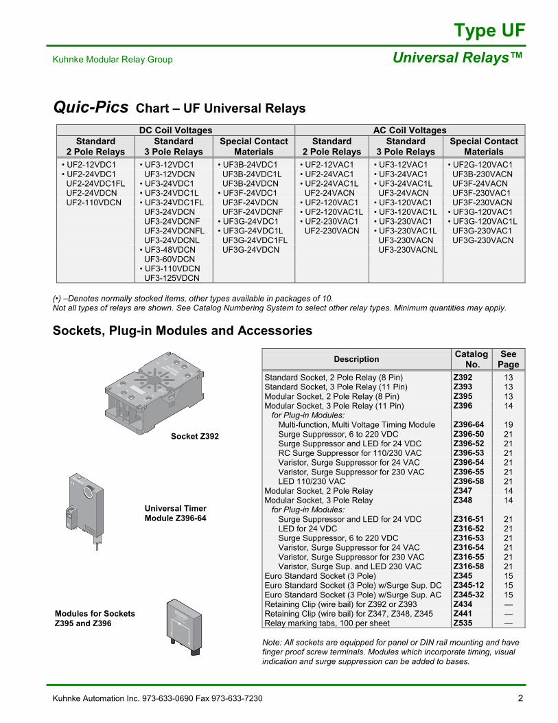
Quic-Pics Chart �– UF Universal Relays
DC Coil Voltages AC Coil VoltagesStandard
2 Pole RelaysStandard
3 Pole RelaysSpecial Contact
MaterialsStandard
2 Pole RelaysStandard
3 Pole RelaysSpecial Contact
Materials�• UF2-12VDC1 �• UF3-12VDC1 �• UF3B-24VDC1 �• UF2-12VAC1 �• UF3-12VAC1 �• UF2G-120VAC1�• UF2-24VDC1 UF3-12VDCN UF3B-24VDC1L �• UF2-24VAC1 �• UF3-24VAC1 UF3B-230VACN UF2-24VDC1FL �• UF3-24VDC1 UF3B-24VDCN �• UF2-24VAC1L �• UF3-24VAC1L UF3F-24VACN UF2-24VDCN �• UF3-24VDC1L �• UF3F-24VDC1 UF2-24VACN UF3-24VACN UF3F-230VAC1 UF2-110VDCN �• UF3-24VDC1FL UF3F-24VDCN �• UF2-120VAC1 �• UF3-120VAC1 UF3F-230VACN
UF3-24VDCN UF3F-24VDCNF �• UF2-120VAC1L �• UF3-120VAC1L �• UF3G-120VAC1 UF3-24VDCNF �• UF3G-24VDC1 �• UF2-230VAC1 �• UF3-230VAC1 �• UF3G-120VAC1L UF3-24VDCNFL �• UF3G-24VDC1L UF2-230VACN �• UF3-230VAC1L UF3G-230VAC1 UF3-24VDCNL UF3G-24VDC1FL UF3-230VACN UF3G-230VACN�• UF3-48VDCN UF3G-24VDCN UF3-230VACNL UF3-60VDCN�• UF3-110VDCN UF3-125VDCN
(�•) �–Denotes normally stocked items, other types available in packages of 10.Not all types of relays are shown. See Catalog Numbering System to select other relay types. Minimum quantities may apply.
Sockets, Plug-in Modules and Accessories
Description Catalog No.
SeePage
Standard Socket, 2 Pole Relay (8 Pin) Z392 13Standard Socket, 3 Pole Relay (11 Pin) Z393 13Modular Socket, 2 Pole Relay (8 Pin) Z395 13Modular Socket, 3 Pole Relay (11 Pin) Z396 14 for Plug-in Modules: Multi-function, Multi Voltage Timing Module Z396-64 19 Surge Suppressor, 6 to 220 VDC Z396-50 21 Surge Suppressor and LED for 24 VDC Z396-52 21 RC Surge Suppressor for 110/230 VAC Z396-53 21 Varistor, Surge Suppressor for 24 VAC Z396-54 21 Varistor, Surge Suppressor for 230 VAC Z396-55 21 LED 110/230 VAC Z396-58 21Modular Socket, 2 Pole Relay Z347 14Modular Socket, 3 Pole Relay Z348 14 for Plug-in Modules: Surge Suppressor and LED for 24 VDC Z316-51 21 LED for 24 VDC Z316-52 21 Surge Suppressor, 6 to 220 VDC Z316-53 21 Varistor, Surge Suppressor for 24 VAC Z316-54 21 Varistor, Surge Suppressor for 230 VAC Z316-55 21 Varistor, Surge Sup. and LED 230 VAC Z316-58 21Euro Standard Socket (3 Pole) Z345 15Euro Standard Socket (3 Pole) w/Surge Sup. DC Z345-12 15Euro Standard Socket (3 Pole) w/Surge Sup. AC Z345-32 15Retaining Clip (wire bail) for Z392 or Z393 Z434 �—Retaining Clip (wire bail) for Z347, Z348, Z345 Z441 �—Relay marking tabs, 100 per sheet Z535 �—
Note: All sockets are equipped for panel or DIN rail mounting and havefinger proof screw terminals. Modules which incorporate timing, visualindication and surge suppression can be added to bases.
Socket Z392
Universal TimerModule Z396-64
Modules for SocketsZ395 and Z396
Rel Z396.63 P Zube
B1
Z396.506/220 V DC
-A2
A2+
3 Kuhnke Automation Inc. 973-633-0690 Fax 973-633-7230
Type UB Universal Relays�™ Kuhnke Modular Relay Group
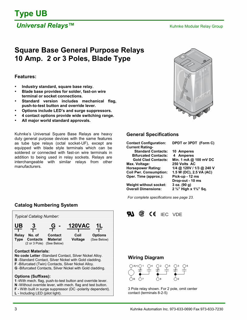
Square Base General Purpose Relays10 Amp. 2 or 3 Poles, Blade Type
Features:
• Industry standard, square base relay.• Blade base provides for solder, fast-on wire
terminal or socket connections.• Standard version includes mechanical flag,
push-to-test button and override lever.• Options include LED�’s and surge suppressors.• 4 contact options provide wide switching range.• All major world standard approvals.
Kuhnke�’s Universal Square Base Relays are heavyduty general purpose devices with the same featuresas tube type relays (octal socket-UF), except areequipped with blade style terminals which can besoldered or connected with fast-on wire terminals inaddition to being used in relay sockets. Relays areinterchangeable with similar relays from othermanufacturers.
General SpecificationsContact Configuration: DPDT or 3PDT (Form C)Current Rating-
Standard Contacts: 10 Amperes Bifurcated Contacts: 4 Amperes
Gold Clad Contacts: Min. 1 mA @ 100 mV DCMax. Voltage: 250 Volts ACHorsepower Rating: 1/4 @ 120V / 1/3 @ 240 VCoil Pwr. Consumption: 1.5 W (DC), 2.5 VA (AC)Oper. Time (approx.): Pick-up - 12 ms
Drop-out - 10 msWeight without socket: 3 oz. (90 g)Overall Dimensions: 2 " High x 1 " Sq.
For complete specifications see page 23.
Catalog Numbering System
Typical Catalog Number:
UB 3 G - 120VAC 1LRelay No. of Contact Coil OptionsType Contacts Material Voltage (See Below) (2 or 3 Pole) (See Below)
Contact Materials:No code Letter -Standard Contact, Silver Nickel Alloy.B -Standard Contact, Silver Nickel with Gold cladding.F -Bifurcated (Twin) Contacts, Silver Nickel Alloy.G -Bifurcated Contacts, Silver Nickel with Gold cladding.
Options (Suffixes):1 -With mech. flag, push-to-test button and override lever.N -Without override lever, with mech. flag and test button.F - With built in surge suppressor (DC -polarity dependent).L - Including LED (pilot light).
Wiring Diagram
3 Pole relay shown. For 2 pole, omit centercontact (terminals 8-2-5)
REL UB3 US P
A(+)
B
1 4
7
2 5
8
3 6
9
IEC VDE
Kuhnke Automation Inc. 973-633-0690 Fax 973-633-7230 4
Type UB Kuhnke Modular Relay Group Universal Relays�™
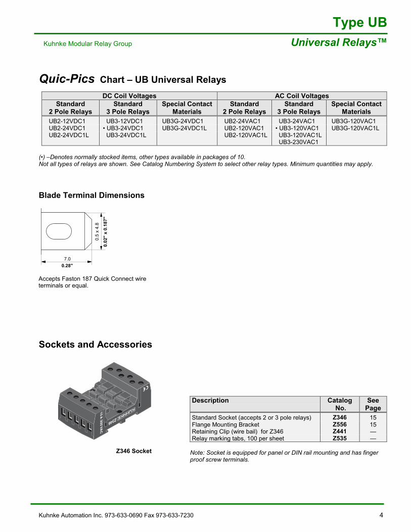
Quic-Pics Chart �– UB Universal Relays
DC Coil Voltages AC Coil VoltagesStandard
2 Pole RelaysStandard
3 Pole RelaysSpecial Contact
MaterialsStandard
2 Pole RelaysStandard
3 Pole RelaysSpecial Contact
Materials UB2-12VDC1 UB3-12VDC1 UB3G-24VDC1 UB2-24VAC1 UB3-24VAC1 UB3G-120VAC1 UB2-24VDC1 �• UB3-24VDC1 UB3G-24VDC1L UB2-120VAC1 �• UB3-120VAC1 UB3G-120VAC1L UB2-24VDC1L UB3-24VDC1L UB2-120VAC1L UB3-120VAC1L
UB3-230VAC1
(�•) �–Denotes normally stocked items, other types available in packages of 10.Not all types of relays are shown. See Catalog Numbering System to select other relay types. Minimum quantities may apply.
Blade Terminal Dimensions
Sockets and Accessories
Description Catalog No.
SeePage
Standard Socket (accepts 2 or 3 pole relays) Z346 15Flange Mounting Bracket Z556 15Retaining Clip (wire bail) for Z346 Z441 �—Relay marking tabs, 100 per sheet Z535 �—
Note: Socket is equipped for panel or DIN rail mounting and has fingerproof screw terminals.
Accepts Faston 187 Quick Connect wireterminals or equal.
Z346 SocketREL_Z346Sockel_ P_US.eps
0.5
x 4.
8
7.0
0.02
" x
0.18
7"
0.28"
5 Kuhnke Automation Inc. 973-633-0690 Fax 973-633-7230
Type 114Quattro Relays�™ Kuhnke Modular Relay Group
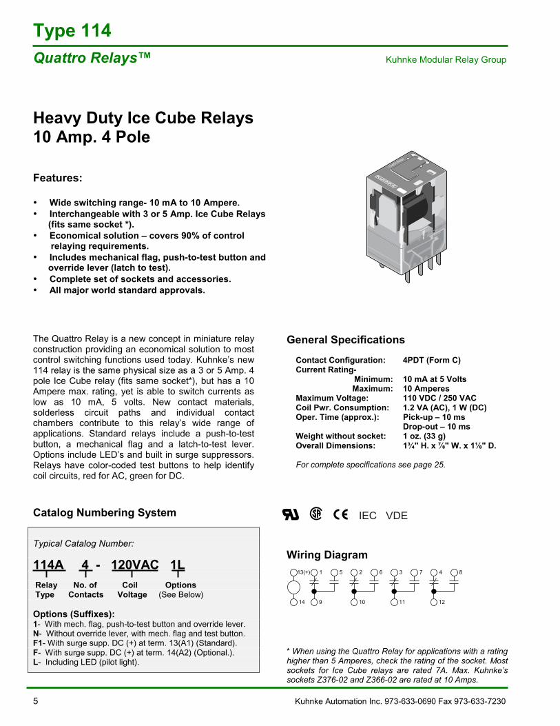
Heavy Duty Ice Cube Relays10 Amp. 4 Pole
Features:
• Wide switching range- 10 mA to 10 Ampere.• Interchangeable with 3 or 5 Amp. Ice Cube Relays (fits same socket *).• Economical solution �– covers 90% of control relaying requirements.• Includes mechanical flag, push-to-test button and override lever (latch to test).• Complete set of sockets and accessories.• All major world standard approvals.
The Quattro Relay is a new concept in miniature relayconstruction providing an economical solution to mostcontrol switching functions used today. Kuhnke�’s new114 relay is the same physical size as a 3 or 5 Amp. 4pole Ice Cube relay (fits same socket*), but has a 10Ampere max. rating, yet is able to switch currents aslow as 10 mA, 5 volts. New contact materials,solderless circuit paths and individual contactchambers contribute to this relay�’s wide range ofapplications. Standard relays include a push-to-testbutton, a mechanical flag and a latch-to-test lever.Options include LED�’s and built in surge suppressors.Relays have color-coded test buttons to help identifycoil circuits, red for AC, green for DC.
Catalog Numbering System
Typical Catalog Number:
114A 4 - 120VAC 1L Relay No. of Coil Options Type Contacts Voltage (See Below)
Options (Suffixes):1- With mech. flag, push-to-test button and override lever.N- Without override lever, with mech. flag and test button.F1- With surge supp. DC (+) at term. 13(A1) (Standard).F- With surge supp. DC (+) at term. 14(A2) (Optional.).L- Including LED (pilot light).
General SpecificationsContact Configuration: 4PDT (Form C)Current Rating-
Minimum: 10 mA at 5 VoltsMaximum: 10 Amperes
Maximum Voltage: 110 VDC / 250 VACCoil Pwr. Consumption: 1.2 VA (AC), 1 W (DC)Oper. Time (approx.): Pick-up �– 10 ms
Drop-out �– 10 msWeight without socket: 1 oz. (33 g)Overall Dimensions: 1¾" H. x " W. x 1 " D.
For complete specifications see page 25.
Wiring Diagram
* When using the Quattro Relay for applications with a ratinghigher than 5 Amperes, check the rating of the socket. Mostsockets for Ice Cube relays are rated 7A. Max. Kuhnke�’ssockets Z376-02 and Z366-02 are rated at 10 Amps.
IEC VDE
13(+)
14
1 5
9
2 6
10
3 7
11
4 8
12
Rel_114A4_SB1_US.eps
REL_114_P.eps
Quattro-Relais
Kuhnke Automation Inc. 973-633-0690 Fax 973-633-7230 6
Type 114 Kuhnke Modular Relay Group Quattro Relays�™
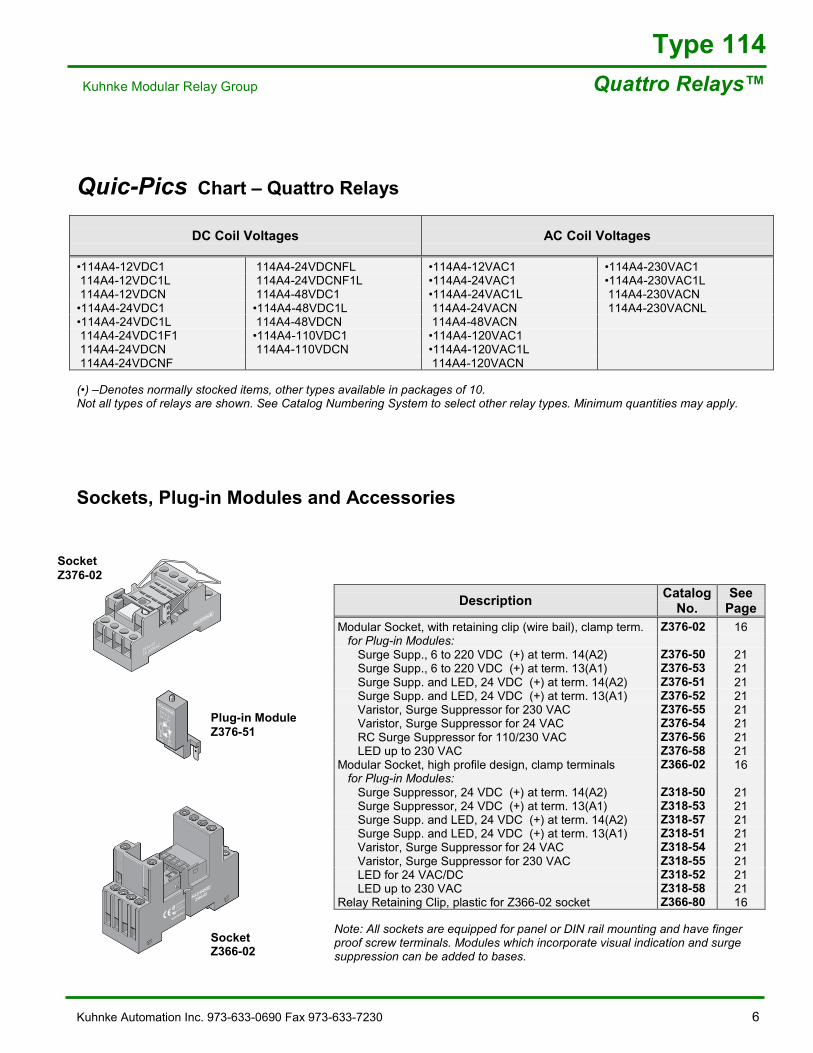
Quic-Pics Chart �– Quattro Relays
DC Coil Voltages AC Coil Voltages
�•114A4-12VDC1 114A4-24VDCNFL �•114A4-12VAC1 �•114A4-230VAC1 114A4-12VDC1L 114A4-24VDCNF1L �•114A4-24VAC1 �•114A4-230VAC1L 114A4-12VDCN 114A4-48VDC1 �•114A4-24VAC1L 114A4-230VACN�•114A4-24VDC1 �•114A4-48VDC1L 114A4-24VACN 114A4-230VACNL�•114A4-24VDC1L 114A4-48VDCN 114A4-48VACN 114A4-24VDC1F1 �•114A4-110VDC1 �•114A4-120VAC1 114A4-24VDCN 114A4-110VDCN �•114A4-120VAC1L 114A4-24VDCNF 114A4-120VACN
(�•) �–Denotes normally stocked items, other types available in packages of 10.Not all types of relays are shown. See Catalog Numbering System to select other relay types. Minimum quantities may apply.
Sockets, Plug-in Modules and Accessories
Description CatalogNo.
SeePage
Modular Socket, with retaining clip (wire bail), clamp term. Z376-02 16 for Plug-in Modules: Surge Supp., 6 to 220 VDC (+) at term. 14(A2) Z376-50 21 Surge Supp., 6 to 220 VDC (+) at term. 13(A1) Z376-53 21 Surge Supp. and LED, 24 VDC (+) at term. 14(A2) Z376-51 21 Surge Supp. and LED, 24 VDC (+) at term. 13(A1) Z376-52 21 Varistor, Surge Suppressor for 230 VAC Z376-55 21 Varistor, Surge Suppressor for 24 VAC Z376-54 21 RC Surge Suppressor for 110/230 VAC Z376-56 21 LED up to 230 VAC Z376-58 21Modular Socket, high profile design, clamp terminals Z366-02 16 for Plug-in Modules: Surge Suppressor, 24 VDC (+) at term. 14(A2) Z318-50 21 Surge Suppressor, 24 VDC (+) at term. 13(A1) Z318-53 21 Surge Supp. and LED, 24 VDC (+) at term. 14(A2) Z318-57 21 Surge Supp. and LED, 24 VDC (+) at term. 13(A1) Z318-51 21 Varistor, Surge Suppressor for 24 VAC Z318-54 21 Varistor, Surge Suppressor for 230 VAC Z318-55 21 LED for 24 VAC/DC Z318-52 21 LED up to 230 VAC Z318-58 21Relay Retaining Clip, plastic for Z366-02 socket Z366-80 16
Note: All sockets are equipped for panel or DIN rail mounting and have fingerproof screw terminals. Modules which incorporate visual indication and surgesuppression can be added to bases.
Rel Z376.02 P Zube
Z376.02
7A 300VAC
Rel Z376.51 P Zube
Z376.5124 V DC
+A2 A1–
SocketZ376-02
Plug-in ModuleZ376-51
Zube_Z366_02_P2.eps
3
Z366.02
MADE IN ITALY
12A 300VAC
LR 26716
10A 300VAC
COIL
COIL
A214
4131
2111
22
42
32NC
4
2
1
514
12
1211
COM10
9
13
A1
SocketZ366-02
7 Kuhnke Automation Inc. 973-633-0690 Fax 973-633-7230
Type 111Miniatur Relays�™ Kuhnke Modular Relay Group
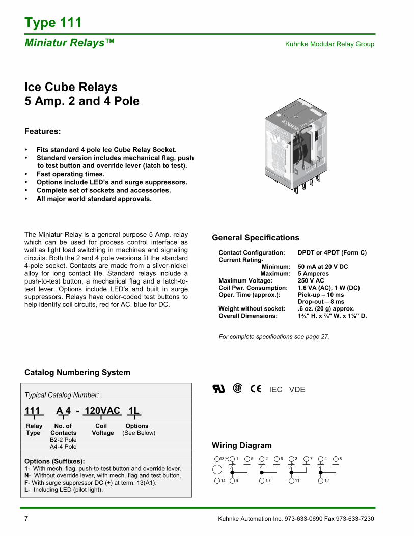
Ice Cube Relays5 Amp. 2 and 4 Pole
Features:
• Fits standard 4 pole Ice Cube Relay Socket.• Standard version includes mechanical flag, push to test button and override lever (latch to test).• Fast operating times.• Options include LED�’s and surge suppressors.• Complete set of sockets and accessories.• All major world standard approvals.
The Miniatur Relay is a general purpose 5 Amp. relaywhich can be used for process control interface aswell as light load switching in machines and signalingcircuits. Both the 2 and 4 pole versions fit the standard4-pole socket. Contacts are made from a silver-nickelalloy for long contact life. Standard relays include apush-to-test button, a mechanical flag and a latch-to-test lever. Options include LED�’s and built in surgesuppressors. Relays have color-coded test buttons tohelp identify coil circuits, red for AC, blue for DC.
Catalog Numbering System
Typical Catalog Number:
111 A 4 - 120VAC 1L Relay No. of Coil Options Type Contacts Voltage (See Below) B2-2 Pole A4-4 Pole
Options (Suffixes):1- With mech. flag, push-to-test button and override lever.N- Without override lever, with mech. flag and test button.F- With surge suppressor DC (+) at term. 13(A1).L- Including LED (pilot light).
General SpecificationsContact Configuration: DPDT or 4PDT (Form C)Current Rating-
Minimum: 50 mA at 20 V DCMaximum: 5 Amperes
Maximum Voltage: 250 V ACCoil Pwr. Consumption: 1.6 VA (AC), 1 W (DC)Oper. Time (approx.): Pick-up �– 10 ms
Drop-out �– 8 msWeight without socket: .6 oz. (20 g) approx.Overall Dimensions: 1¾" H. x " W. x 1 " D.
For complete specifications see page 27.
Wiring Diagram
REL_111_P.eps
Miniatur111A4-230VACN
5A/250 VAC
9
15
10
26
11
37
12
48
13(A1)14(A2)
13(+)
14
1 5
9
2 6
10
3 7
11
4 8
12
IEC VDE
Kuhnke Automation Inc. 973-633-0690 Fax 973-633-7230 8
Type 111 Kuhnke Modular Relay Group Miniatur Relays�™
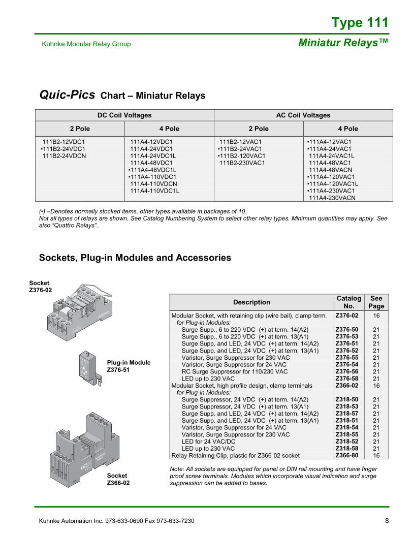
Quic-Pics Chart �– Miniatur Relays
DC Coil Voltages AC Coil Voltages
2 Pole 4 Pole 2 Pole 4 Pole
111B2-12VDC1 111A4-12VDC1 111B2-12VAC1 �•111A4-12VAC1 �•111B2-24VDC1 111A4-24VDC1 �•111B2-24VAC1 �•111A4-24VAC1 111B2-24VDCN 111A4-24VDC1L �•111B2-120VAC1 111A4-24VAC1L
111A4-48VDC1 111B2-230VAC1 111A4-48VAC1�•111A4-48VDC1L 111A4-48VACN�•111A4-110VDC1 �•111A4-120VAC1 111A4-110VDCN �•111A4-120VAC1L 111A4-110VDC1L �•111A4-230VAC1
111A4-230VACN
(�•) �–Denotes normally stocked items, other types available in packages of 10.Not all types of relays are shown. See Catalog Numbering System to select other relay types. Minimum quantities may apply. Seealso �“Quattro Relays�”.
Sockets, Plug-in Modules and Accessories
Description CatalogNo.
SeePage
Modular Socket, with retaining clip (wire bail), clamp term. Z376-02 16 for Plug-in Modules: Surge Supp., 6 to 220 VDC (+) at term. 14(A2) Z376-50 21 Surge Supp., 6 to 220 VDC (+) at term. 13(A1) Z376-53 21 Surge Supp. and LED, 24 VDC (+) at term. 14(A2) Z376-51 21 Surge Supp. and LED, 24 VDC (+) at term. 13(A1) Z376-52 21 Varistor, Surge Suppressor for 230 VAC Z376-55 21 Varistor, Surge Suppressor for 24 VAC Z376-54 21 RC Surge Suppressor for 110/230 VAC Z376-56 21 LED up to 230 VAC Z376-58 21Modular Socket, high profile design, clamp terminals Z366-02 16 for Plug-in Modules: Surge Suppressor, 24 VDC (+) at term. 14(A2) Z318-50 21 Surge Suppressor, 24 VDC (+) at term. 13(A1) Z318-53 21 Surge Supp. and LED, 24 VDC (+) at term. 14(A2) Z318-57 21 Surge Supp. and LED, 24 VDC (+) at term. 13(A1) Z318-51 21 Varistor, Surge Suppressor for 24 VAC Z318-54 21 Varistor, Surge Suppressor for 230 VAC Z318-55 21 LED for 24 VAC/DC Z318-52 21 LED up to 230 VAC Z318-58 21Relay Retaining Clip, plastic for Z366-02 socket Z366-80 16
Note: All sockets are equipped for panel or DIN rail mounting and have fingerproof screw terminals. Modules which incorporate visual indication and surgesuppression can be added to bases.
Rel Z376.51 P Zube
Z376.5124 V DC
+A2 A1–
Plug-in ModuleZ376-51
Rel Z376.02 P Zube
Z376.02
7A 300VAC
SocketZ376-02
Zube_Z366_02_P2.eps
3
Z366.02
MADE IN ITALY
12A 300VAC
LR 26716
10A 300VAC
COIL
COIL
A214
4131
2111
22
42
32NC
4
2
1
514
12
1211
COM10
9
13
A1
SocketZ366-02
9 Kuhnke Automation Inc. 973-633-0690 Fax 973-633-7230
107G1-12VDC
107G2-12VDC
107P1-12VDC
Type 107PCB Interface Relays Kuhnke Modular Relay Group
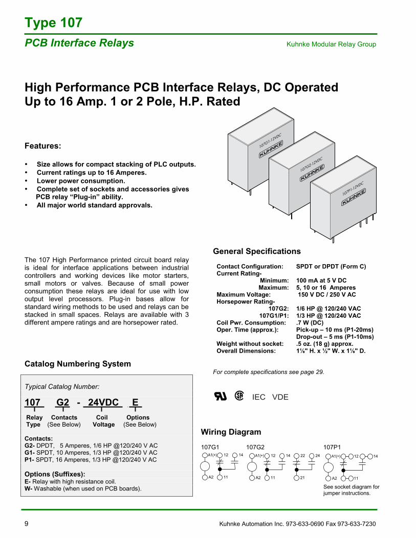
High Performance PCB Interface Relays, DC OperatedUp to 16 Amp. 1 or 2 Pole, H.P. Rated
Features:
• Size allows for compact stacking of PLC outputs.• Current ratings up to 16 Amperes.• Lower power consumption.• Complete set of sockets and accessories gives PCB relay �“Plug-in�” ability.• All major world standard approvals.
The 107 High Performance printed circuit board relayis ideal for interface applications between industrialcontrollers and working devices like motor starters,small motors or valves. Because of small powerconsumption these relays are ideal for use with lowoutput level processors. Plug-in bases allow forstandard wiring methods to be used and relays can bestacked in small spaces. Relays are available with 3different ampere ratings and are horsepower rated.
Catalog Numbering System
Typical Catalog Number:
107 G2 - 24VDC E Relay Contacts Coil Options Type (See Below) Voltage (See Below)
Contacts:G2- DPDT, 5 Amperes, 1/6 HP @120/240 V ACG1- SPDT, 10 Amperes, 1/3 HP @120/240 V ACP1- SPDT, 16 Amperes, 1/3 HP @120/240 V AC
Options (Suffixes):E- Relay with high resistance coil.W- Washable (when used on PCB boards).
General SpecificationsContact Configuration: SPDT or DPDT (Form C)Current Rating-
Minimum: 100 mA at 5 V DCMaximum: 5, 10 or 16 Amperes
Maximum Voltage: 150 V DC / 250 V ACHorsepower Rating-
107G2: 1/6 HP @ 120/240 VAC107G1/P1: 1/3 HP @ 120/240 VAC
Coil Pwr. Consumption: .7 W (DC)Oper. Time (approx.): Pick-up �– 10 ms (P1-20ms)
Drop-out �– 5 ms (P1-10ms)Weight without socket: .5 oz. (18 g) approx.Overall Dimensions: 1 " H. x ½" W. x 1 " D.
For complete specifications see page 29.
IEC VDE
A1(+)
A2
12 14
11
A1(+)
A2
12 14
11
22 24
21
A1(+)
A2
12 14
11
Wiring Diagram
107G1 107G2 107P1
See socket diagram forjumper instructions.
Kuhnke Automation Inc. 973-633-0690 Fax 973-633-7230 10
Type 107 Kuhnke Modular Relay Group PCB Interface Relays
Quic-Pics Chart �– High Performance PCB Interface Relays (DC Operated)
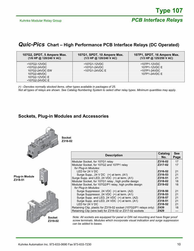
107G2, DPDT, 5 Ampere Max.(1/6 HP @ 120/240 V AC)
107G1, SPDT, 10 Ampere Max.(1/3 HP @ 120/240 V AC)
107P1, SPDT, 16 Ampere Max.(1/3 HP @ 125/250 V AC)
�•107G2-12VDC �•107G1-12VDC �•107P1-12VDC �•107G2-24VDC �•107G1-24VDC 107P1-12VDC E 107G2-24VDC EW �•107G1-24VDC E �•107P1-24VDC 107G2-48VDC 107P1-24VDC E 107G2-12VDC E �•107G2-24VDC E
(�•) �–Denotes normally stocked items, other types available in packages of 25.Not all types of relays are shown. See Catalog Numbering System to select other relay types. Minimum quantities may apply.
Sockets, Plug-in Modules and Accessories
Description CatalogNo.
SeePage
Modular Socket, for 107G1 relay Z316-02 17Modular Socket, for 107G2 and 107P1 relay Z317-02 17 for Plug-in Modules: LED for 24 V DC Z316-52 21 Surge Supp., 24 V DC (+) at term. (A1) Z316-53 21Surge Supp. and LED, 24 VDC (+) at term. (A1) Z316-51 21Modular Socket, for 107G1 relay , high profile design Z318-02 18Modular Socket, for 107G2/P1 relay, high profile design Z319-02 18 for Plug-in Modules: Surge Suppressor, 24 VDC (+) at term. (A2) Z318-50 21 Surge Suppressor, 24 VDC (+) at term. (A1) Z318-53 21 Surge Supp. and LED, 24 VDC (+) at term. (A2) Z318-57 21 Surge Supp. and LED, 24 VDC (+) at term. (A1) Z318-51 21 LED for 24 V DC Z318-52 21Retaining Clip, plastic for Z319-02 socket (107G2/P1 relays only) Z439 18Retaining Clip (wire bail) for Z316-02 or Z317-02 sockets Z429 �—
Note: All sockets are equipped for panel or DIN rail mounting and have finger proofscrew terminals. Modules which incorporate visual indication and surge suppressioncan be added to bases.
Plug-in ModuleZ318-51
SocketZ316-02
REL_Z31602_P.eps
A1
1112
A2
CO
IL
Z316.02
A1
1112
A2
CO
IL
Z316.02REL_Z31851_P.eps
A1+
-A2
Z318.516/24 V DC
REL_Z31902_P.eps
11
Z319.02
A1A2 12
14
21
A1A2
2224
21
1214
11
12A 300VAC
LR 26716
10A 300VAC
24
NO14
A2
COILA1
22
NO
12
SocketZ319-02
11 Kuhnke Automation Inc. 973-633-0690 Fax 973-633-7230
Type 171PCB Interface Relays Kuhnke Modular Relay Group
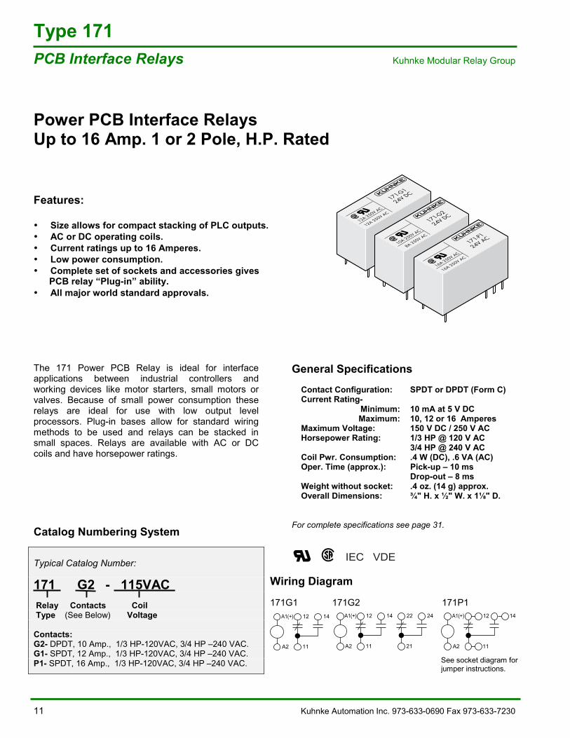
Power PCB Interface RelaysUp to 16 Amp. 1 or 2 Pole, H.P. Rated
Features:
• Size allows for compact stacking of PLC outputs.• AC or DC operating coils.• Current ratings up to 16 Amperes.• Low power consumption.• Complete set of sockets and accessories gives PCB relay �“Plug-in�” ability.• All major world standard approvals.
The 171 Power PCB Relay is ideal for interfaceapplications between industrial controllers andworking devices like motor starters, small motors orvalves. Because of small power consumption theserelays are ideal for use with low output levelprocessors. Plug-in bases allow for standard wiringmethods to be used and relays can be stacked insmall spaces. Relays are available with AC or DCcoils and have horsepower ratings.
Catalog Numbering System
Typical Catalog Number:
171 G2 - 115VAC Relay Contacts Coil Type (See Below) Voltage
Contacts:G2- DPDT, 10 Amp., 1/3 HP-120VAC, 3/4 HP �–240 VAC.G1- SPDT, 12 Amp., 1/3 HP-120VAC, 3/4 HP �–240 VAC.P1- SPDT, 16 Amp., 1/3 HP-120VAC, 3/4 HP �–240 VAC.
General SpecificationsContact Configuration: SPDT or DPDT (Form C)Current Rating-
Minimum: 10 mA at 5 V DCMaximum: 10, 12 or 16 Amperes
Maximum Voltage: 150 V DC / 250 V ACHorsepower Rating: 1/3 HP @ 120 V AC
3/4 HP @ 240 V ACCoil Pwr. Consumption: .4 W (DC), .6 VA (AC)Oper. Time (approx.): Pick-up �– 10 ms
Drop-out �– 8 msWeight without socket: .4 oz. (14 g) approx.Overall Dimensions: ¾" H. x ½" W. x 1 " D.
For complete specifications see page 31.
IEC VDE
171-G1
24V DC
12A 250V AC
12A 250V AC
171-G2
24V DC
10A 250V AC
8A 250V AC
171-P1
24V AC
16A 250V AC
16A 250V AC
Rel171Gruppe_P_US.eps
A1(+)
A2
12 14
11
22 24
21
A1(+)
A2
12 14
11
Rel_171PI_SB1_
A1(+)
A2
12 14
11
Rel_171G1_SB1_US.eps
Wiring Diagram
171G1 171G2 171P1
See socket diagram forjumper instructions.
Kuhnke Automation Inc. 973-633-0690 Fax 973-633-7230 12
Type 171 Kuhnke Modular Relay Group PCB Interface Relays
Quic-Pics Chart �– Power PCB Interface Relays
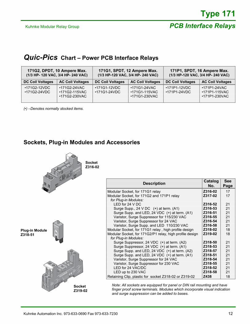
171G2, DPDT, 10 Ampere Max.(1/3 HP- 120 VAC, 3/4 HP- 240 VAC)
171G1, SPDT, 12 Ampere Max.(1/3 HP-120 VAC, 3/4 HP- 240 VAC)
171P1, SPDT, 16 Ampere Max.(1/3 HP-120 VAC, 3/4 HP- 240 VAC)
DC Coil Voltages AC Coil Voltages DC Coil Voltages AC Coil Voltages DC Coil Voltages AC Coil Voltages �•171G2-12VDC �•171G2-24VAC �•171G1-12VDC �•171G1-24VAC �•171P1-12VDC �•171P1-24VAC �•171G2-24VDC �•171G2-115VAC �•171G1-24VDC �•171G1-115VAC �•171P1-24VDC �•171P1-115VAC
�•171G2-230VAC �•171G1-230VAC �•171P1-230VAC
(�•) �–Denotes normally stocked items.
Sockets, Plug-in Modules and Accessories
Description CatalogNo.
SeePage
Modular Socket, for 171G1 relay Z316-02 17Modular Socket, for 171G2 and 171P1 relay Z317-02 17 for Plug-in Modules: LED for 24 V DC Z316-52 21 Surge Supp., 24 V DC (+) at term. (A1) Z316-53 21 Surge Supp. and LED, 24 VDC (+) at term. (A1) Z316-51 21 Varistor, Surge Suppressor for 115/230 VAC Z316-55 21 Varistor, Surge Suppressor for 24 VAC Z316-54 21 Varistor, Surge Supp. and LED 110/230 VAC Z316-58 21Modular Socket, for 171G1 relay , high profile design Z318-02 18Modular Socket, for 171G2/P1 relay, high profile design Z319-02 18 for Plug-in Modules: Surge Suppressor, 24 VDC (+) at term. (A2) Z318-50 21 Surge Suppressor, 24 VDC (+) at term. (A1) Z318-53 21 Surge Supp. and LED, 24 VDC (+) at term. (A2) Z318-57 21 Surge Supp. and LED, 24 VDC (+) at term. (A1) Z318-51 21 Varistor, Surge Suppressor for 24 VAC Z318-54 21 Varistor, Surge Suppressor for 230 VAC Z318-55 21 LED for 24 VAC/DC Z318-52 21 LED up to 230 VAC Z318-58 21Retaining Clip, plastic for socket Z318-02 or Z319-02 Z438 18
Note: All sockets are equipped for panel or DIN rail mounting and havefinger proof screw terminals. Modules which incorporate visual indicationand surge suppression can be added to bases.
Plug-in ModuleZ318-51
SocketZ316-02
REL_Z31602_P.eps
A1
1112
A2
CO
IL
Z316.02
A1
1112
A2
CO
IL
Z316.02
REL_Z31851_P.eps
A1+
-A2
Z318.516/24 V DC
REL_Z31902_P.eps
11
Z319.02
A1A2 12
14
21
A1A2
2224
21
1214
11
12A 300VAC
LR 26716
10A 300VAC
24
NO14
A2
COILA1
22
NO
12
SocketZ319-02
13 Kuhnke Automation Inc. 973-633-0690 Fax 973-633-7230
AccessoriesRelay Sockets Kuhnke Modular Relay Group
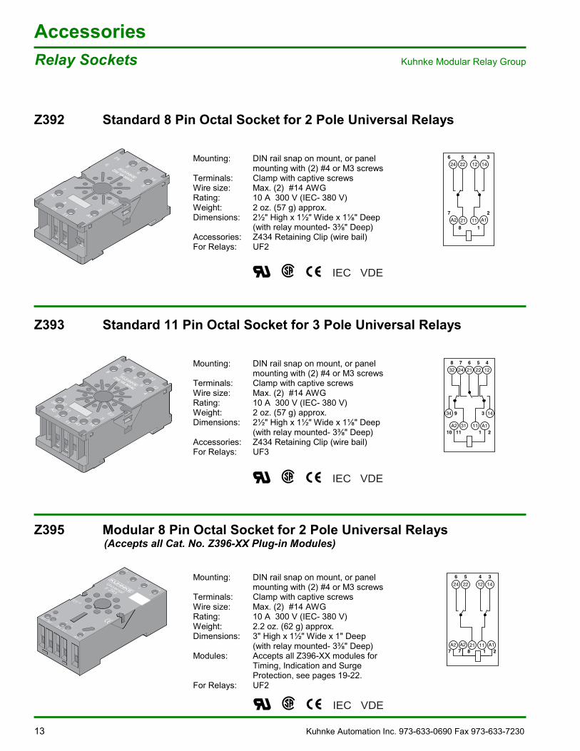
Z392 Standard 8 Pin Octal Socket for 2 Pole Universal Relays
Mounting: DIN rail snap on mount, or panelmounting with (2) #4 or M3 screws
Terminals: Clamp with captive screwsWire size: Max. (2) #14 AWGRating: 10 A 300 V (IEC- 380 V)Weight: 2 oz. (57 g) approx.Dimensions: 2½" High x 1½" Wide x 1 " Deep
(with relay mounted- 3 " Deep)Accessories: Z434 Retaining Clip (wire bail)For Relays: UF2
Z393 Standard 11 Pin Octal Socket for 3 Pole Universal Relays
Mounting: DIN rail snap on mount, or panelmounting with (2) #4 or M3 screws
Terminals: Clamp with captive screwsWire size: Max. (2) #14 AWGRating: 10 A 300 V (IEC- 380 V)Weight: 2 oz. (57 g) approx.Dimensions: 2½" High x 1½" Wide x 1 " Deep
(with relay mounted- 3 " Deep)Accessories: Z434 Retaining Clip (wire bail)For Relays: UF3
Z395 Modular 8 Pin Octal Socket for 2 Pole Universal Relays (Accepts all Cat. No. Z396-XX Plug-in Modules)
Mounting: DIN rail snap on mount, or panelmounting with (2) #4 or M3 screws
Terminals: Clamp with captive screwsWire size: Max. (2) #14 AWGRating: 10 A 300 V (IEC- 380 V)Weight: 2.2 oz. (62 g) approx.Dimensions: 3" High x 1½" Wide x 1" Deep
(with relay mounted- 3 " Deep)Modules: Accepts all Z396-XX modules for
Timing, Indication and SurgeProtection, see pages 19-22.
For Relays: UF2
D11
6
3
218
111 2
7
A1
A2
522
412
24
14
Z392 10A 380VAC
D11
6
3
218
111 2
7
A1
A2
522
412
24
14
Z392 10A 380VAC
Rel Z392 P Zube
246
7
3
2
5 4
8 1
A2 A11121
22 12 14
REL_Z392_SB
Rel Z393 P Zube
8
4
3E2
9
2
10
111
14
34
A1
A2
11
31
7
5
621
32
12
24
22Z393 10A 380VAC
8
4
3E2
9
2
10
111
14
34
A1
A2
11
31
7
5
621
32
12
24
22Z393 10A 380VAC
32
34 9
A2 3110 11
11 A11 2
143
24 21 22 128 7 6 5 4
REL_Z393_SB
IEC VDE
IEC VDE
IEC VDE
24
A2A2 A11121
22 12 14
6
77 218
5 4 3
REL_Z395_P_US.epsZubeh r Relaissockel
10A 400VAC
12A 300VAC
LR 26716
10A 300VAC
E 113714
Universalz 395
246 22
5
77
81
2
124 14
A2A2
2111
A1
3
MADE INITALY
Kuhnke Automation Inc. 973-633-0690 Fax 973-633-7230 14
AccessoriesKuhnke Modular Relay Group Relay Sockets
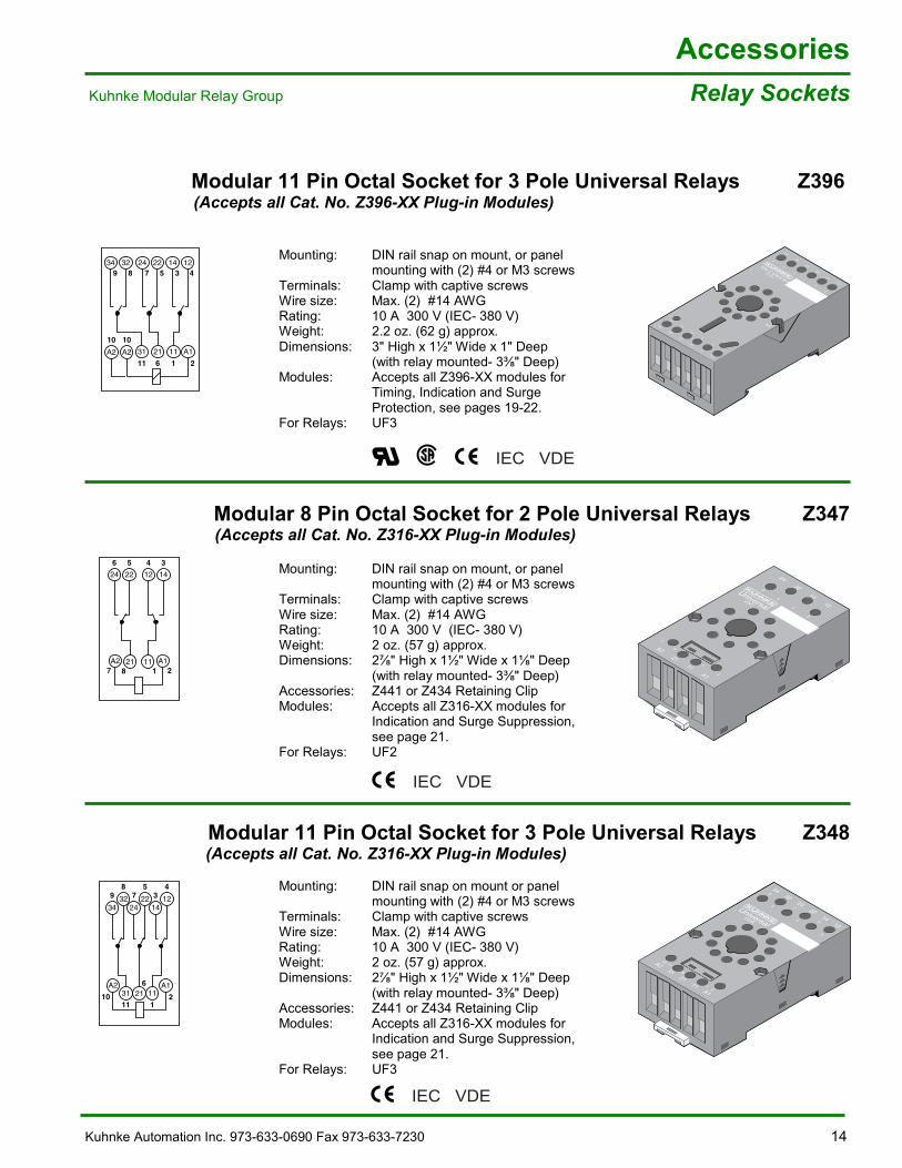
Modular 11 Pin Octal Socket for 3 Pole Universal Relays Z396 (Accepts all Cat. No. Z396-XX Plug-in Modules)
Mounting: DIN rail snap on mount, or panelmounting with (2) #4 or M3 screws
Terminals: Clamp with captive screwsWire size: Max. (2) #14 AWGRating: 10 A 300 V (IEC- 380 V)Weight: 2.2 oz. (62 g) approx.Dimensions: 3" High x 1½" Wide x 1" Deep
(with relay mounted- 3 " Deep)Modules: Accepts all Z396-XX modules for
Timing, Indication and SurgeProtection, see pages 19-22.
For Relays: UF3
Modular 8 Pin Octal Socket for 2 Pole Universal Relays Z347 (Accepts all Cat. No. Z316-XX Plug-in Modules)
Mounting: DIN rail snap on mount, or panelmounting with (2) #4 or M3 screws
Terminals: Clamp with captive screwsWire size: Max. (2) #14 AWGRating: 10 A 300 V (IEC- 380 V)Weight: 2 oz. (57 g) approx.Dimensions: 2 " High x 1½" Wide x 1 " Deep
(with relay mounted- 3 " Deep)Accessories: Z441 or Z434 Retaining ClipModules: Accepts all Z316-XX modules for
Indication and Surge Suppression,see page 21.
For Relays: UF2
Modular 11 Pin Octal Socket for 3 Pole Universal Relays Z348 (Accepts all Cat. No. Z316-XX Plug-in Modules)
Mounting: DIN rail snap on mount or panelmounting with (2) #4 or M3 screws
Terminals: Clamp with captive screwsWire size: Max. (2) #14 AWGRating: 10 A 300 V (IEC- 380 V)Weight: 2 oz. (57 g) approx.Dimensions: 2 " High x 1½" Wide x 1 " Deep
(with relay mounted- 3 " Deep)Accessories: Z441 or Z434 Retaining ClipModules: Accepts all Z316-XX modules for
Indication and Surge Suppression,see page 21.
For Relays: UF3
24
22
32
34
14
12
31
21
A2
A2
11
A1
11
6
10
10
1
2
7
5
E5
8
9
3
4
Universal
Z396
REL_Z396_Px.epsZubehör Relaissockel
24
22
32
34
14
12
31
21
A2
A2
11
A1
11
6
10
10
1
2
7
5
E5
8
9
3
4
34 32 24 22 14 129 8 7 5 3 4
A2 A2
10 1031 21 11
11 6 1 2A1
REL_Z396_SB1_US.eps
2422
1412
6
5
4
3
A221
11A1
7
2
1
8
UniversalZ347
2422
1412
6
5
4
3
A221
11A1
7
2
1
8
UniversalZ347
Rel Z347 P Zube
24
A2 A11121
22 12 14
6
7 218
5 4 3
REL_Z347_SB1_US.eps
3432
2422
14129
87
53
4
A11121
631
A2
2111
10
REL Z348 SB1 US eps
UniversalZ348
3432
24
2131
A210
21
6
11
11A1
2214
12
8
5
4
9
7
3
Rel Z348 P Zube
IEC VDE
IEC VDE
IEC VDE
15 Kuhnke Automation Inc. 973-633-0690 Fax 973-633-7230
AccessoriesRelay Sockets Kuhnke Modular Relay Group
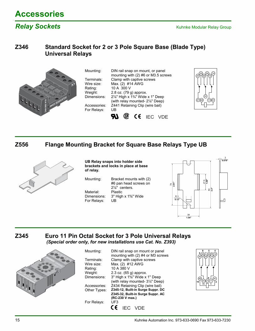
Z346 Standard Socket for 2 or 3 Pole Square Base (Blade Type)Universal Relays
Mounting: DIN rail snap on mount, or panelmounting with (2) #6 or M3.5 screws
Terminals: Clamp with captive screwsWire size: Max. (2) #14 AWGRating: 10 A 300 VWeight: 2.8 oz. (79 g) approx.Dimensions: 2 " High x 1¾" Wide x 1" Deep
(with relay mounted- 2 " Deep)Accessories: Z441 Retaining Clip (wire bail)For Relays: UB
Z556 Flange Mounting Bracket for Square Base Relays Type UB
UB Relay snaps into holder sidebrackets and locks in place at baseof relay.
Mounting: Bracket mounts with (2)#6 pan head screws on2 " centers.
Material: PlasticDimensions: 3" High x 1 " WideFor Relays: UB
Z345 Euro 11 Pin Octal Socket for 3 Pole Universal Relays (Special order only, for new installations use Cat. No. Z393)
Mounting: DIN rail snap on mount or panelmounting with (2) #4 or M3 screws
Terminals: Clamp with captive screwsWire size: Max. (2) #12 AWGRating: 10 A 380 VWeight: 2.3 oz. (65 g) approx.Dimensions: 3" High x 1 " Wide x 1" Deep
(with relay mounted- 3¼" Deep)Accessories: Z434 Retaining Clip (wire bail)Other Types: Z345-12, Built-in Surge Suppr. DC
Z345-32, Built-in Surge Suppr. AC(RC-230 V max.)
For Relays: UF3
REL_Z346Sockel_ P_US.eps
98
75
34
6
2111
10
2224
3234
1214
A111
31
A221
REL_Z346_SB
REL_Z556Halterung_ P_US.eps
3432
2422
14129
87
53
4
A11121
631
A2
2111
10
IEC VDE
IEC VDE
UniversalZ345.12
34 329
8 225 12
4
247143
A2
21 11A1
31
1011
6 1
2
74
2
R 3
27.5
84
39
2.91
"
0.12"
1.08
"
3.3"
0.078"
1.54"
Kuhnke Automation Inc. 972-633-0690 Fax 973-633-7230 16
AccessoriesKuhnke Modular Relay Group Relay Sockets
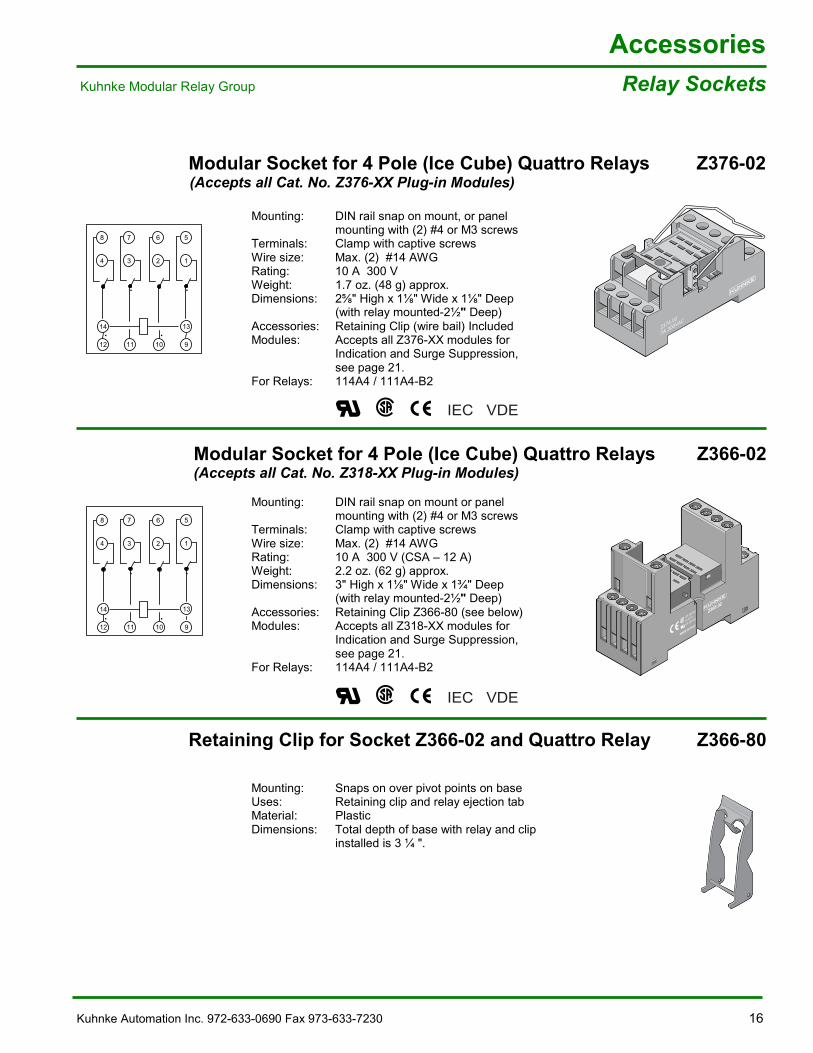
Modular Socket for 4 Pole (Ice Cube) Quattro Relays Z376-02 (Accepts all Cat. No. Z376-XX Plug-in Modules)
Mounting: DIN rail snap on mount, or panelmounting with (2) #4 or M3 screws
Terminals: Clamp with captive screwsWire size: Max. (2) #14 AWGRating: 10 A 300 VWeight: 1.7 oz. (48 g) approx.Dimensions: 2 " High x 1 " Wide x 1 " Deep
(with relay mounted-2½" Deep)Accessories: Retaining Clip (wire bail) IncludedModules: Accepts all Z376-XX modules for
Indication and Surge Suppression,see page 21.
For Relays: 114A4 / 111A4-B2
Modular Socket for 4 Pole (Ice Cube) Quattro Relays Z366-02 (Accepts all Cat. No. Z318-XX Plug-in Modules)
Mounting: DIN rail snap on mount or panelmounting with (2) #4 or M3 screws
Terminals: Clamp with captive screwsWire size: Max. (2) #14 AWGRating: 10 A 300 V (CSA �– 12 A)Weight: 2.2 oz. (62 g) approx.Dimensions: 3" High x 1 " Wide x 1¾" Deep
(with relay mounted-2½" Deep)Accessories: Retaining Clip Z366-80 (see below)Modules: Accepts all Z318-XX modules for
Indication and Surge Suppression,see page 21.
For Relays: 114A4 / 111A4-B2
Retaining Clip for Socket Z366-02 and Quattro Relay Z366-80
Mounting: Snaps on over pivot points on baseUses: Retaining clip and relay ejection tabMaterial: PlasticDimensions: Total depth of base with relay and clip
installed is 3 ¼ ".
Rel Z376.02 P Zube
Z376.02
7A 300VAC
REL_Z37602_SB.eps
8
4
14
12
7
3
11
6
2
10
5
1
9
13
REL_Z37602_SB.eps
8
4
14
12
7
3
11
6
2
10
5
1
9
13
Zube_Z366_02_P2.eps
3
Z366.02
MADE IN ITALY
12A 300VAC
LR 26716
10A 300VAC
COIL
COIL
A2
14
4131
2111
22
NC
4
2
1
514
12
1211
COM10
9
13
A1
IEC VDE
IEC VDE
REL_Z36680Clip_ P_US.eps
17 Kuhnke Automation Inc. 973-633-0690 Fax 973-633-7230
AccessoriesRelay Sockets Kuhnke Modular Relay Group
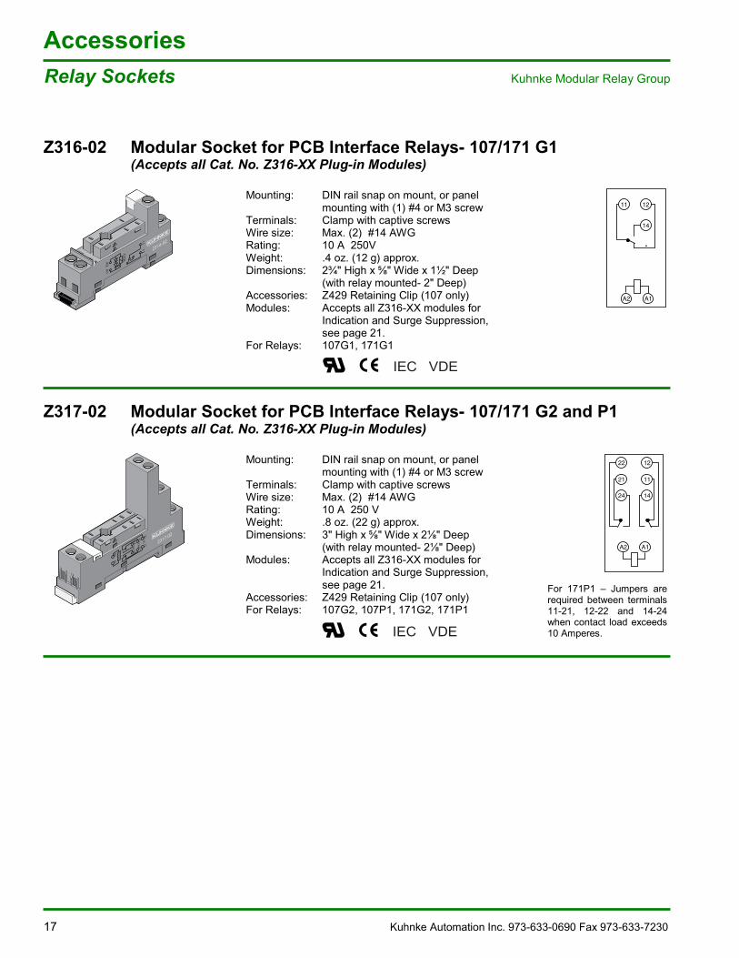
Z316-02 Modular Socket for PCB Interface Relays- 107/171 G1(Accepts all Cat. No. Z316-XX Plug-in Modules)
Mounting: DIN rail snap on mount, or panelmounting with (1) #4 or M3 screw
Terminals: Clamp with captive screwsWire size: Max. (2) #14 AWGRating: 10 A 250VWeight: .4 oz. (12 g) approx.Dimensions: 2¾" High x " Wide x 1½" Deep
(with relay mounted- 2" Deep)Accessories: Z429 Retaining Clip (107 only)Modules: Accepts all Z316-XX modules for
Indication and Surge Suppression,see page 21.
For Relays: 107G1, 171G1
Z317-02 Modular Socket for PCB Interface Relays- 107/171 G2 and P1(Accepts all Cat. No. Z316-XX Plug-in Modules)
Mounting: DIN rail snap on mount, or panelmounting with (1) #4 or M3 screw
Terminals: Clamp with captive screwsWire size: Max. (2) #14 AWGRating: 10 A 250 VWeight: .8 oz. (22 g) approx.Dimensions: 3" High x " Wide x 2 " Deep
(with relay mounted- 2 " Deep)Modules: Accepts all Z316-XX modules for
Indication and Surge Suppression,see page 21.
Accessories: Z429 Retaining Clip (107 only)For Relays: 107G2, 107P1, 171G2, 171P1
REL_Z31602_P.eps
A1
1112
A2
CO
IL
Z316.02
A1
1112
A2
CO
IL
Z316.02
REL_Z31702_P.eps
Z317.02
A1
A2
222124 121114
NCC
OMN
O
CO
IL
Z317.02
A1
A2
222124 121114
NCC
OMN
O
CO
IL
IEC VDE
IEC VDE
REL_Z31602_S
11 12
14
A2 A1
REL_Z31702_SB
22 12
24 14
21 11
A2 A1
For 171P1 �– Jumpers arerequired between terminals11-21, 12-22 and 14-24when contact load exceeds10 Amperes.
Kuhnke Automation Inc. 973-633-0690 Fax 973-633-7230 18
AccessoriesKuhnke Modular Relay Group Relay Sockets
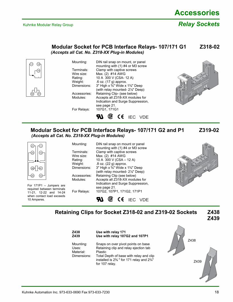
Modular Socket for PCB Interface Relays- 107/171 G1 Z318-02 (Accepts all Cat. No. Z318-XX Plug-in Modules)
Mounting: DIN rail snap on mount, or panelmounting with (1) #4 or M3 screw
Terminals: Clamp with captive screwsWire size: Max. (2) #14 AWGRating: 10 A 300 V (CSA- 12 A)Weight: .6 oz. (17 g) approx.Dimensions: 3" High x " Wide x 1¾" Deep
(with relay mounted- 2 " Deep)Accessories: Retaining Clip- (see below)Modules: Accepts all Z318-XX modules for
Indication and Surge Suppression,see page 21.
For Relays: 107G1, 171G1
Modular Socket for PCB Interface Relays- 107/171 G2 and P1 Z319-02 (Accepts all Cat. No. Z318-XX Plug-in Modules)
Mounting: DIN rail snap on mount or panelmounting with (1) #4 or M3 screw
Terminals: Clamp with captive screwsWire size: Max. (2) #14 AWGRating: 10 A 300 V (CSA �– 12 A)Weight: .8 oz. (22 g) approx.Dimensions: 3" High x " Wide x 1¾" Deep
(with relay mounted- 2 " Deep)Accessories: Retaining Clip (see below)Modules: Accepts all Z318-XX modules for
Indication and Surge Suppression,see page 21.
For Relays: 107G2, 107P1, 171G2, 171P1
Retaining Clips for Socket Z318-02 and Z319-02 Sockets Z438Z439
Z438 Use with relay 171Z439 Use with relay 107G2 and 107P1
Mounting: Snaps on over pivot points on baseUses: Retaining clip and relay ejection tabMaterial: PlasticDimensions: Total Depth of base with relay and clip
installed is 2 " for 171 relay and 2¾"for 107 relay.
REL_Z31802_P.eps
NO
14
Z318.02
A1A2 12
14
21
12A 300VAC
LR 26716
10A 300VAC
A2COIL
A1
11OONO
12
REL_Z31902_P.eps
11
Z319.02
A1A2 12
14
21
A1A2
2224
21
1214
11
12A 300VAC
LR 26716
10A 300VAC
24
NO14
A2
COILA1
22
NO
12
REL_Z438_ P.eps
Z438
Z439
IEC VDE
IEC VDE
_Z31602_SB.eps
11 12
14
A2 A1
L_Z31902_SB.eps
14
11
24
21
A2 A1
22 12
For 171P1 �– Jumpers arerequired between terminals11-21, 12-22 and 14-24when contact load exceeds10 Amperes.
19 Kuhnke Automation Inc. 973-633-0690 Fax 973-633-7230
AccessoriesTiming Module Kuhnke Modular Relay Group
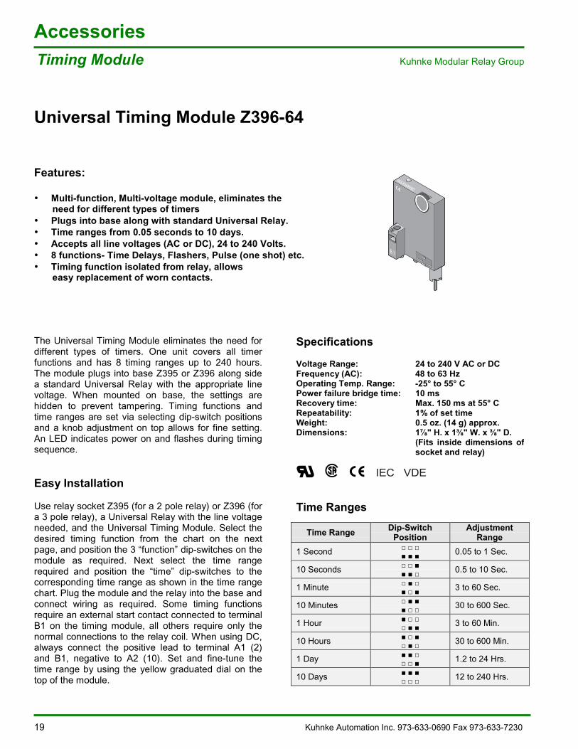
Universal Timing Module Z396-64
Features:
• Multi-function, Multi-voltage module, eliminates the need for different types of timers• Plugs into base along with standard Universal Relay.• Time ranges from 0.05 seconds to 10 days.• Accepts all line voltages (AC or DC), 24 to 240 Volts.• 8 functions- Time Delays, Flashers, Pulse (one shot) etc.• Timing function isolated from relay, allows easy replacement of worn contacts.
The Universal Timing Module eliminates the need fordifferent types of timers. One unit covers all timerfunctions and has 8 timing ranges up to 240 hours.The module plugs into base Z395 or Z396 along sidea standard Universal Relay with the appropriate linevoltage. When mounted on base, the settings arehidden to prevent tampering. Timing functions andtime ranges are set via selecting dip-switch positionsand a knob adjustment on top allows for fine setting.An LED indicates power on and flashes during timingsequence.
Easy Installation
Use relay socket Z395 (for a 2 pole relay) or Z396 (fora 3 pole relay), a Universal Relay with the line voltageneeded, and the Universal Timing Module. Select thedesired timing function from the chart on the nextpage, and position the 3 �“function�” dip-switches on themodule as required. Next select the time rangerequired and position the �“time�” dip-switches to thecorresponding time range as shown in the time rangechart. Plug the module and the relay into the base andconnect wiring as required. Some timing functionsrequire an external start contact connected to terminalB1 on the timing module, all others require only thenormal connections to the relay coil. When using DC,always connect the positive lead to terminal A1 (2)and B1, negative to A2 (10). Set and fine-tune thetime range by using the yellow graduated dial on thetop of the module.
Specifications
Voltage Range: 24 to 240 V AC or DCFrequency (AC): 48 to 63 HzOperating Temp. Range: -25° to 55° CPower failure bridge time: 10 msRecovery time: Max. 150 ms at 55° CRepeatability: 1% of set timeWeight: 0.5 oz. (14 g) approx.Dimensions: 1 " H. x 1 " W. x " D.
(Fits inside dimensions ofsocket and relay)
Time Ranges
Time Range Dip-SwitchPosition
AdjustmentRange
1 Second 0.05 to 1 Sec.
10 Seconds 0.5 to 10 Sec.
1 Minute 3 to 60 Sec.
10 Minutes 30 to 600 Sec.
1 Hour 3 to 60 Min.
10 Hours 30 to 600 Min.
1 Day 1.2 to 24 Hrs.
10 Days 12 to 240 Hrs.
Rel Z396.63 P Zube
B1
IEC VDE
Kuhnke Automation Inc. 973-633-0690 Fax 973-633-7230 20
AccessoriesKuhnke Modular Relay Group Timing Module
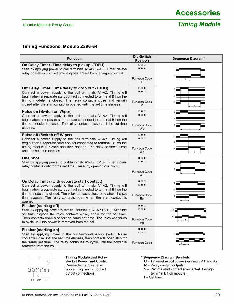
Timing Functions, Module Z396-64
Function Dip-SwitchPosition Sequence Diagram*
On Delay Timer (Time delay to pickup -TDPU)Start by applying power to coil terminals A1-A2 (2-10). Timer delaysrelay operation until set time elapses. Reset by opening coil circuit.
Function CodeE
U
R
t
Off Delay Timer (Time delay to drop out -TDDO)Connect a power supply to the coil terminals A1-A2. Timing willbegin when a separate start contact connected to terminal B1 on thetiming module, is closed. The relay contacts close and remainclosed after the start contact is opened until the set time elapses.
Function CodeR
S
U
R
t
Pulse on (Switch on Wiper)Connect a power supply to the coil terminals A1-A2. Timing willbegin when a separate start contact connected to terminal B1 on thetiming module, is closed. The relay contacts close until the set timeelapses.
Function CodeWs
S
U
R
t
Pulse off (Switch off Wiper)Connect a power supply to the coil terminals A1-A2. Timing willbegin after a separate start contact connected to terminal B1 on thetiming module is closed and then opened. The relay contacts closeuntil the set time elapses.
Function CodeWa
S
U
R
t
One ShotStart by applying power to coil terminals A1-A2 (2-10). Timer closesrelay contacts only for the set time. Reset by opening coil circuit.
Function CodeWu
U
R
t
On Delay Timer (with separate start contact)Connect a power supply to the coil terminals A1-A2. Timing willbegin when a separate start contact connected to terminal B1 on thetiming module, is closed. The relay contacts close only after the settime elapses. The relay contacts open when the start contact isopened.
Function CodeEs
S
U
R
t
Flasher (starting off)Start by applying power to the coil terminals A1-A2 (2-10). After theset time elapses the relay contacts close, again for the set time.Then contacts open also for the same set time. The relay continuesto cycle until the power is removed from the coil.
Function CodeBp
U
R
tt
Flasher (starting on)Start by applying power to the coil terminals A1-A2 (2-10). Relaycontacts close until the set time elapses, then contacts open also forthe same set time. The relay continues to cycle until the power isremoved from the coil.
Function CodeBi
U
R
tt
* Sequence Diagram Symbols U �– Timer/relay coil power (terminals A1 and A2). R �– Relay contact outputs. S �– Remote start contact (connected through terminal B1 on module).
Timing Module and RelaySocket Power and ControlConnections. See relaysocket diagram for contactoutput connections.
t �– Set time.
A2
–(~)
A131 21B1 11
+(~)Start
21 Kuhnke Automation Inc. 973-633-0690 Fax 973-633-7230
AccessoriesPlug-in Modules Kuhnke Modular Relay Group
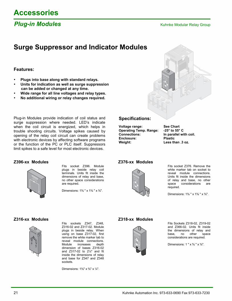
Surge Suppressor and Indicator Modules
Features:
• Plugs into base along with standard relays.• Units for indication as well as surge suppression can be added or changed at any time.• Wide range for all line voltages and relay types.• No additional wiring or relay changes required.
Plug-in Modules provide indication of coil status andsurge suppression where needed. LED�’s indicatewhen the coil circuit is energized, which helps introuble shooting circuits. Voltage spikes caused byopening of the relay coil circuit can create problemswith electronic devices by affecting software programsor the function of the PC or PLC itself. Suppressorslimit spikes to a safe level for most electronic devices.
Specifications:Voltage range: See ChartOperating Temp. Range: -25° to 55° CConnections: In parallel with coil.Enclosure: PlasticWeight: Less than .3 oz.
Z396-xx Modules Z376-xx Modules
Z396.506/220 V DC
-A2
A2+
Fits socket Z396. Moduleplugs in beside relay coilterminals. Units fit inside thedimensions of relay and base,no other space considerationsare required.
Dimensions: 1 " x 1 " x ".
Z376.5124 V DC
+A2 A1–
Fits socket Z376. Remove thewhite marker tab on socket toreveal module connections.Units fit inside the dimensionsof relay and base, no otherspace considerations arerequired.
Dimensions: 1 " x 1 " x ".
Z316-xx Modules Z318-xx Modules
+
24 V DC
–
Fits sockets Z347, Z348,Z316-02 and Z317-02. Moduleplugs in beside relay. Whenusing on base Z317-02, firstremove the white marker tab toreveal module connections.Module increases depthdimension of bases Z316-02and Z317-02 to 2¼" and fitinside the dimensions of relayand base for Z347 and Z348sockets.
Dimensions: 1 " x " x ¼".
A1+
-A2
Z318.516/24 V DC
Fits Sockets Z318-02, Z319-02and Z366-02. Units fit insidethe dimensions of relay andbase, no other spaceconsiderations are required.
Dimensions: 1 " x " x ".
Rel Z376.02 P Zube
Z376.02
7A 300VAC
Quattro-Relais
Z376.5124 V DC
+A2 A1–
Kuhnke Automation Inc. 973-633-0690 Fax 973-633-7230 22
AccessoriesKuhnke Modular Relay Group Plug-in Modules
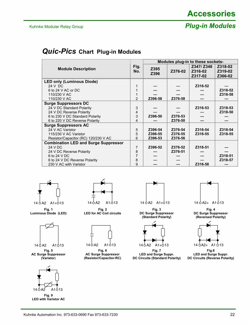
Quic-Pics Chart Plug-in Modules
Modules plug-in to these sockets-
Module Description Fig.No. Z395
Z396 Z376-02Z347/ Z348Z316-02Z317-02
Z318-02Z319-02Z366-02
LED only (Luminous Diode) 24 V DC 1 �— �— Z316-52 �— 6 to 24 V AC or DC 1 �— �— �— Z318-52 110/230 V AC 1 �— �— �— Z318-58 110/230 V AC 2 Z396-58 Z376-58 �— �—Surge Suppressors DC 24 V DC Standard Polarity 3 �— �— Z316-53 Z318-53 24 V DC Reverse Polarity 4 �— �— �— Z318-50 6 to 230 V DC Standard Polarity 3 Z396-50 Z376-53 �— �— 6 to 220 V DC Reverse Polarity 4 �— Z376-50 �— �—Surge Suppressors AC 24 V AC Varistor 5 Z396-54 Z376-54 Z316-54 Z318-54 115/230 V AC Varistor 5 Z396-55 Z376-55 Z316-55 Z318-55 Resistor/Capacitor (RC) 120/230 V AC 6 Z396-53 Z376-56Combination LED and Surge Suppressor 24 V DC 7 Z396-52 Z376-52 Z316-51 �— 24 V DC Reverse Polarity 8 �— Z376-51 �— �— 6 to 24 V DC 7 �— �— �— Z318-51 6 to 24 V DC Reverse Polarity 8 �— �— �— Z318-57 230 V AC with Varistor 9 �— �— Z316-58 �—
A1+A214 13
Fig. 1Luminous Diode (LED)
A1A214 13
Fig. 2LED for AC Coil circuits
A1+A214 13
Fig. 3DC Surge Suppressor
(Standard Polarity)
A1A2+14 13
Fig. 4DC Surge Suppressor
(Reversed Polarity)
A1A214 13Fig. 5
AC Surge Suppressor(Varistor)
A1A214 13Fig. 6
AC Surge Suppressor(Resistor/Capacitor-RC)
A1+A214 13Fig. 7
LED and Surge Suppr.DC Circuits (Standard Polarity)
A1A2+14 13Fig.8
LED and Surge Suppr.DC Circuits (Reverse Polarity)
A1A214 13
Fig. 9LED with Varistor AC
23 Kuhnke Automation Inc. 973.633.0690 Fax 973.633.7230
Technical SpecificationsUniversal Relays�™ Kuhnke Modular Relay Group
Detailed Specifications UF/UB Relays
General Information
Number of contacts: 2 or 3 PoleContact type: Double Throw (Form C)
Single or Bifurcated(Twin) contacts
Max. Voltage: 250 VAC/DCCurrent ratings: See Contact DataWeight: 3 oz. (90 grams)
Performance Information
Pick-up time: 12 msDrop out time: 10 msContact bounce time: 5 msMechanical Life: 20 million plus operationsElectrical Life: See ChartsOperating Ambient Temp: -25°C to +40°CVibration Resistance: Greater than 4g�’sDielectric Strength-
Coil to Contact: 2500 VAC Between Poles: 2500 VAC
Between open contacts: 1500 VAC
Standards
UL File: E 41922CSA: LR 47569VDE: According to DIN EN 60255-1-00
VDE 0435 part 201IEC: According to IEC255-1-00NEMA: B300 Pilot DutyCE: Low Voltage Directive
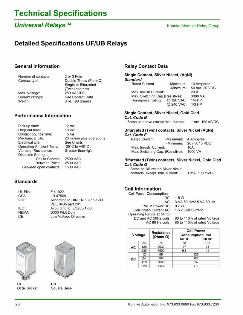
Relay Contact DataSingle Contact, Silver Nickel, (AgNi)Standard Rated Current -Maximum: 10 Amperes
-Minimum: 50 mA 20 VDC Max. Inrush Current: 20 A. Max. Switching Cap.(Resistive): 3000 VA Horsepower rating @ 120 VAC: 1/4 HP
@ 240 VAC: 1/3 HP
Single Contact, Silver Nickel, Gold CladCat. Code B Same as above except min. current: 1 mA 100 mVDC
Bifurcated (Twin) contacts, Silver Nickel (AgNi)Cat. Code F Rated Current -Maximum: 4 Amperes
-Minimum: 20 mA 10 VDC Max. Inrush Current: 10A. Max. Switching Cap. (Resistive): 1000 VA
Bifurcated (Twin) contacts, Silver Nickel, Gold CladCat. Code G Same as Bifurcated Silver Nickel contacts except min. current: 1 mA 100 mVDC
Coil InformationCoil Power Consumption-
DC: 1.5 WAC: 3 VA 50 Hz/2.5 VA 60 Hz
Pull in Power DC: 0.7 WCoil Inrush Current AC: 1.5 x Coil Current
Operating Range @ 20°C-DC and AC 50Hz coils: 80 to 110% of rated Voltage
AC 60 Hz coils: 85 to 110% of rated Voltage
Coil PowerConsumption mAVoltage Resistance
(Ohms- ) 60 Hz 50 Hz24 74 88 105120 2030 17 21AC230 7500 9.8 1212 96 12524 384 63110 7660 14
DC
220 30630 7.2
REL UB3 US P
Universal
UF3 - 24VDC N
Rel UF3 P Dist
UF UBOctal Socket Square Base
Kuhnke Automation Inc. 973.633.0690 Fax 973.633.7230 24
Technical SpecificationsKuhnke Modular Relay Group Universal Relays�™
Detailed Specifications UF/UB Relays
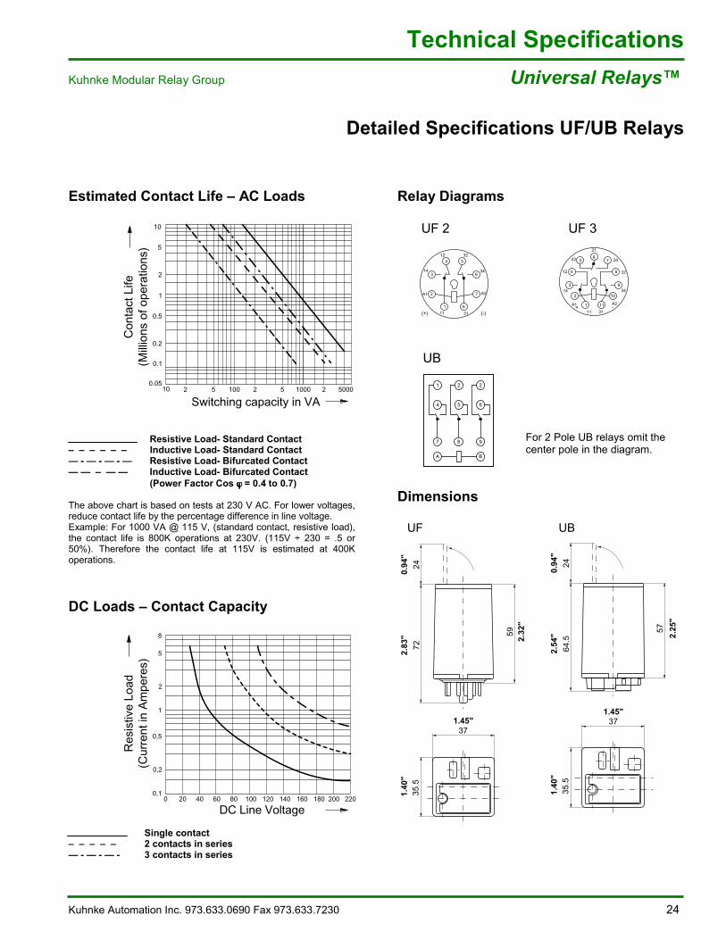
Estimated Contact Life �– AC Loads
Resistive Load- Standard Contact�– �– �– �– �– �– Inductive Load- Standard Contact�— - �— - �— - �— Resistive Load- Bifurcated Contact�— �— �– �— �— Inductive Load- Bifurcated Contact
(Power Factor Cos ϕ ϕ ϕ ϕ = 0.4 to 0.7)
The above chart is based on tests at 230 V AC. For lower voltages,reduce contact life by the percentage difference in line voltage.Example: For 1000 VA @ 115 V, (standard contact, resistive load),the contact life is 800K operations at 230V. (115V ÷ 230 = .5 or50%). Therefore the contact life at 115V is estimated at 400Koperations.
DC Loads �– Contact Capacity
Single contact�– �– �– �– �– 2 contacts in series�— - �— - �— - 3 contacts in series
Relay Diagrams
UF 2 UF 3
UB
For 2 Pole UB relays omit thecenter pole in the diagram.
Dimensions
UF UB
REL_112UF2_SB.eps
12
14
32
34
A2A1
11 31(+) (-)
4 5
6
7
81
2
3
21
22
12
14
24
32
34
A2A1
11 31
REL_112UF3_SB.eps
+ -
675
4 8
93
2 10
111
A B
7
1
4
2
5
2
6
8 9
REL_UB_US.eps
35.5
1.
40"
592.
32"
7224
2.83
"0.
94"
371.45"
Rel Ufx M US.eps
57
2.25
"
35.5
1.
40"
64.5
242.
54"
0.94
"
371.45"
31Rel_Ubx_M_US.eps
2 5 2 5 2 5000100 1000
Con
tact
Life
(Mill
ions
of o
pera
tions
)
Switching capacity in VA10
0.05
0.2
0.5
0.1
1
10
2
5
REL_Ufx_DIA1_US.eps
0 20 40 60 80 100 120 140 160 1800,1
0,5
1
0,2
5
8
2
200 220
Res
istiv
e Lo
ad(C
urre
nt in
Am
pere
s)
DC Line Voltage
25 Kuhnke Automation Inc. 973.633.0690 Fax 973.633.7230
Technical SpecificationsQuattro Relays�™ Kuhnke Modular Relay Group
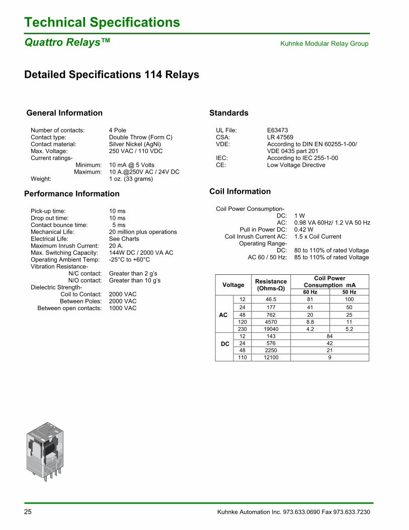
Detailed Specifications 114 Relays
General Information
Number of contacts: 4 PoleContact type: Double Throw (Form C)Contact material: Silver Nickel (AgNi)Max. Voltage: 250 VAC / 110 VDCCurrent ratings-
Minimum: 10 mA @ 5 VoltsMaximum: 10 A.@250V AC / 24V DC
Weight: 1 oz. (33 grams)
Performance Information
Pick-up time: 10 msDrop out time: 10 msContact bounce time: 5 msMechanical Life: 20 million plus operationsElectrical Life: See ChartsMaximum Inrush Current: 20 A.Max. Switching Capacity: 144W DC / 2000 VA ACOperating Ambient Temp: -25°C to +60°CVibration Resistance-
N/C contact: Greater than 2 g�’sN/O contact: Greater than 10 g�’s
Dielectric Strength-Coil to Contact: 2000 VACBetween Poles: 2000 VAC
Between open contacts: 1000 VAC
Standards
UL File: E63473CSA: LR 47569VDE: According to DIN EN 60255-1-00/
VDE 0435 part 201IEC: According to IEC 255-1-00CE: Low Voltage Directive
Coil Information
Coil Power Consumption-DC: 1 WAC: 0.98 VA 60Hz/ 1.2 VA 50 Hz
Pull in Power DC: 0.42 WCoil Inrush Current AC: 1.5 x Coil Current
Operating Range-DC: 80 to 110% of rated Voltage
AC 60 / 50 Hz: 85 to 110% of rated Voltage
Coil PowerConsumption mAVoltage Resistance
(Ohms- ) 60 Hz 50 Hz12 46.5 81 10024 177 41 5048 762 20 25120 4570 8.8 11
AC
230 19040 4.2 5.212 143 8424 576 4248 2250 21
DC
110 12100 9
REL_114_P.eps
Quattro-Relais
Kuhnke Automation Inc. 973.633.0690 Fax 973.633.7230 26
Technical SpecificationsKuhnke Modular Relay Group Quattro Relays�™
Detailed Specifications 114 Relays
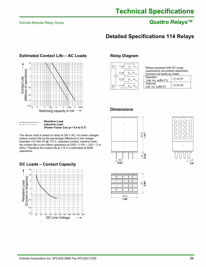
Estimated Contact Life �– AC Loads Relay Diagram
Relays equipped with DC surgesuppressors are polarity dependent.Connect coil leads as noted.Standard (cat. no. suffix F1) (+) to A1
Optional(cat. no. suffix F) (+) to A2
Dimensions
Resistive Load�– �– �– �– �– �– Inductive Load
(Power Factor Cos = 0.4 to 0.7)
The above chart is based on tests at 230 V AC. For lower voltagesreduce contact life by the percentage difference in line voltage.Example: For 500 VA @ 115 V, (standard contact, resistive load),the contact life is one million operations at 230V. (115V ÷ 230 = .5 or50%). Therefore the contact life at 115 V is estimated at 500Koperations.
DC Loads �– Contact Capacity
REL114A4_SB.eps
13
14
9
10
11
12 8 4
7 3
6 2
5 1(13)
(14)
(9)
(12)
A1
A2
11
41 44 42
14 12
(8)
(5)
(4)
(1)
(10)21 24 22
(6) (2)
(11)31 34 32
(7) (3)
2 5 2 5 2 5000100 1000
Con
tact
Life
(Mill
ions
of o
pera
tions
)
Switching capacity in VA10
0.05
0.2
0.5
0.1
1
10
2
5
20 40 60 80 100 120 140 160 220180 20000,1
0,5
1
0,2
5
10
20
2
Res
istiv
e Lo
ad(C
urre
nt in
Am
pere
s)
DC Line Voltage
REL_114_M_US.eps
637
.4
27.5
21
0.5 2
1.08"
0.02" 0.8"
0.23
"1.
47"
0.82
"
27 Kuhnke Automation Inc. 973.633.0690 Fax 973.633.7230
Technical SpecificationsMiniatur Relays�™ Kuhnke Modular Relay Group
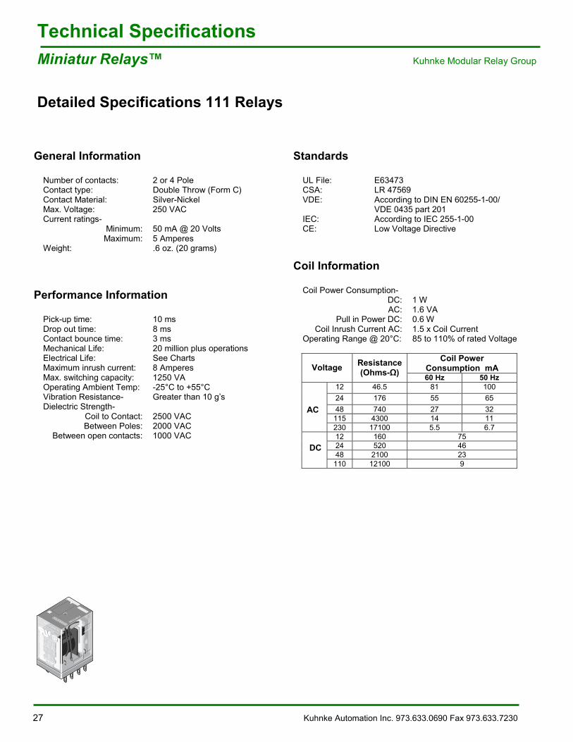
Detailed Specifications 111 Relays
General Information
Number of contacts: 2 or 4 PoleContact type: Double Throw (Form C)Contact Material: Silver-NickelMax. Voltage: 250 VACCurrent ratings-
Minimum: 50 mA @ 20 VoltsMaximum: 5 Amperes
Weight: .6 oz. (20 grams)
Performance Information
Pick-up time: 10 msDrop out time: 8 msContact bounce time: 3 msMechanical Life: 20 million plus operationsElectrical Life: See ChartsMaximum inrush current: 8 AmperesMax. switching capacity: 1250 VAOperating Ambient Temp: -25°C to +55°CVibration Resistance- Greater than 10 g�’sDielectric Strength-
Coil to Contact: 2500 VACBetween Poles: 2000 VAC
Between open contacts: 1000 VAC
Standards
UL File: E63473CSA: LR 47569VDE: According to DIN EN 60255-1-00/
VDE 0435 part 201IEC: According to IEC 255-1-00CE: Low Voltage Directive
Coil Information
Coil Power Consumption-DC: 1 WAC: 1.6 VA
Pull in Power DC: 0.6 WCoil Inrush Current AC: 1.5 x Coil Current
Operating Range @ 20°C: 85 to 110% of rated Voltage
Coil PowerConsumption mAVoltage Resistance
(Ohms- ) 60 Hz 50 Hz12 46.5 81 10024 176 55 6548 740 27 32115 4300 14 11
AC
230 17100 5.5 6.712 160 7524 520 4648 2100 23
DC
110 12100 9
REL 111 P eps
Miniatur111A4-230VACN
5A/250 VAC
9
15
10
26
11
37
12
48
13(A1)14(A2)
Kuhnke Automation Inc. 973.633.0690 Fax 973.633.7230 28
Technical SpecificationsKuhnke Modular Relay Group Miniatur Relays�™
Detailed Specifications 111 Relays
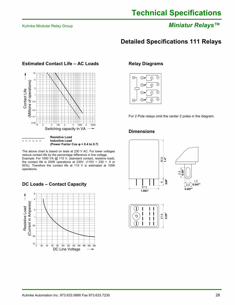
Estimated Contact Life �– AC Loads
Resistive Load�– �– �– �– �– �– Inductive Load
(Power Factor Cos = 0.4 to 0.7)
The above chart is based on tests at 230 V AC. For lower voltagesreduce contact life by the percentage difference in line voltage.Example: For 1000 VA @ 115 V, (standard contact, resistive load),the contact life is 200K operations at 230V. (115V ÷ 230 = .5 or50%). Therefore the contact life at 115 V is estimated at 100Koperations.
DC Loads �– Contact Capacity
Relay Diagrams
For 2 Pole relays omit the center 2 poles in the diagram.
Dimensions
2 5 2 5 2 5000100 1000
Rel_111_Dia1_US.eps
Con
tact
Life
(Mill
ions
of o
pera
tions
)
Switching capacity in VA10
0.05
0.2
0.5
0.1
1
10
2
5
0 20 40 60 80 100 120 140 160 180 200 2200,1
0,5
1
0,2
5
8
2
Res
istiv
e Lo
ad(C
urre
nt in
Am
pere
s)
DC Line Voltage
REL_111A4_SB.eps
13
14
9
10
11
12 8 4
7 3
6 2
5 1
21.6
27.5
35.6
6
0.85
"
1.083"
1.4"
0.24
"
1.20.047"2.2
0.087"
2.3
0.09
"
REL_111_M_US.eps
29 Kuhnke Automation Inc. 973.633.0690 fax 973.633.7230
Technical SpecificationsPCB Interface Relays Kuhnke Modular Relay Group
Detailed Specifications 107 Relays
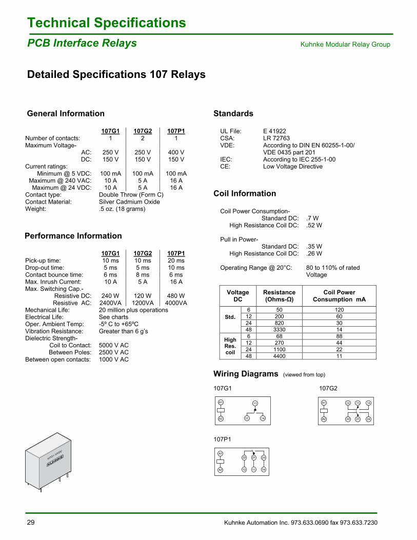
General Information
107G1 107G2 107P1Number of contacts: 1 2 1Maximum Voltage-
AC: 250 V 250 V 400 VDC: 150 V 150 V 150 V
Current ratings:Minimum @ 5 VDC: 100 mA 100 mA 100 mA
Maximum @ 240 VAC: 10 A 5 A 16 AMaximum @ 24 VDC: 10 A 5 A 16 A
Contact type: Double Throw (Form C)Contact Material: Silver Cadmium OxideWeight: .5 oz. (18 grams)
Performance Information
107G1 107G2 107P1Pick-up time: 10 ms 10 ms 20 msDrop-out time: 5 ms 5 ms 10 msContact bounce time: 6 ms 8 ms 6 msMax. Inrush Current: 10 A 5 A 16 AMax. Switching Cap.-
Resistive DC: 240 W 120 W 480 WResistive AC: 2400VA 1200VA 4000VA
Mechanical Life: 20 million plus operationsElectrical Life: See chartsOper. Ambient Temp: -5º C to +65ºCVibration Resistance: Greater than 6 g�’sDielectric Strength-
Coil to Contact: 5000 V ACBetween Poles: 2500 V AC
Between open contacts: 1000 V AC
Standards
UL File: E 41922CSA: LR 72763VDE: According to DIN EN 60255-1-00/
VDE 0435 part 201IEC: According to IEC 255-1-00CE: Low Voltage Directive
Coil Information
Coil Power Consumption-Standard DC: .7 W
High Resistance Coil DC: .52 W
Pull in Power-Standard DC: .35 W
High Resistance Coil DC: .26 W
Operating Range @ 20°C: 80 to 110% of ratedVoltage
VoltageDC
Resistance(Ohms- )
Coil PowerConsumption mA
6 50 12012 200 6024 820 30
Std.
48 3330 146 68 88
12 270 4424 1100 22
HighRes.coil
48 4400 11
Wiring Diagrams (viewed from top)
107G1 107G2
107P1
REL107G1_P.eps
107G1-12VDC
REL107G1_SB.eps
A1
A2
11
1412
REL107G2_SB.eps
A1
A2
12 11 14
22 21 24
A1
A2
22 21 24
12 11 14
Kuhnke Automation Inc. 973.633.7230 Fax 973.633.7230 30
Technical SpecificationsKuhnke Modular Relay Group PCB Interface Relays
Detailed Specifications 107 Relays
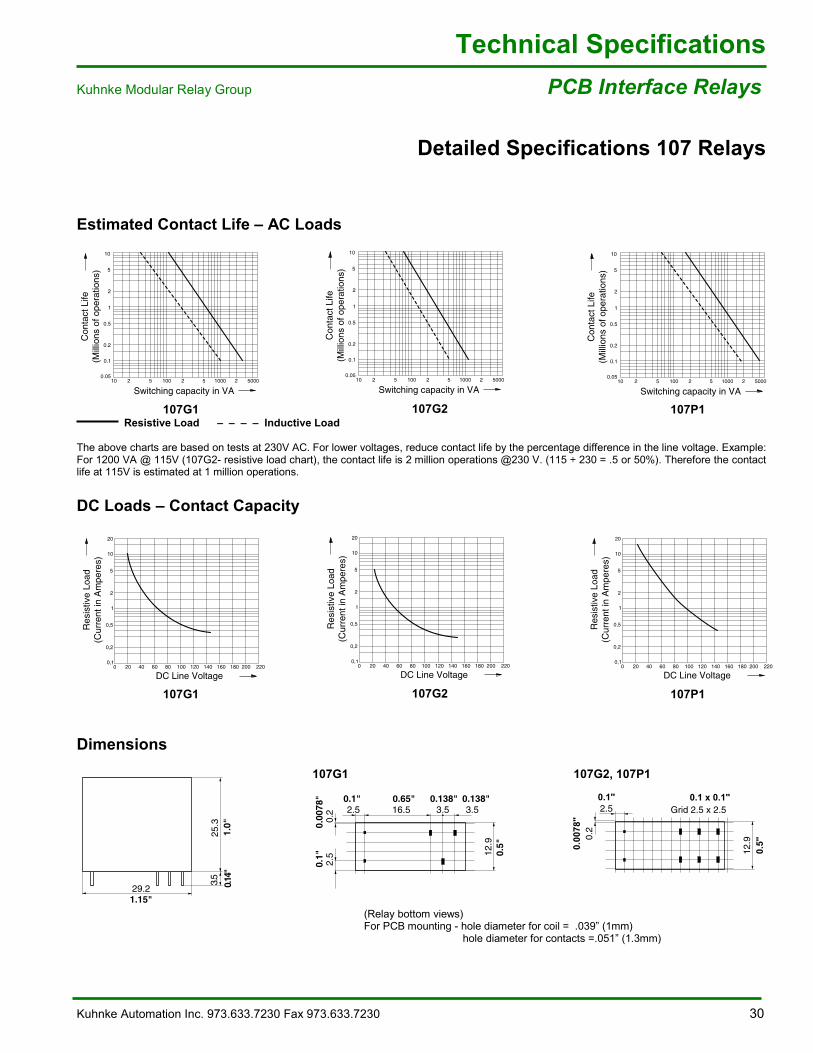
Estimated Contact Life �– AC Loads
Resistive Load �– �– �– �– Inductive Load
The above charts are based on tests at 230V AC. For lower voltages, reduce contact life by the percentage difference in the line voltage. Example:For 1200 VA @ 115V (107G2- resistive load chart), the contact life is 2 million operations @230 V. (115 ÷ 230 = .5 or 50%). Therefore the contactlife at 115V is estimated at 1 million operations.
DC Loads �– Contact Capacity
Dimensions
107G1 107G2, 107P1
(Relay bottom views)For PCB mounting - hole diameter for coil = .039�” (1mm)
hole diameter for contacts =.051�” (1.3mm)
2 5 2 5 2 5000100 1000
Rel_107G1_Dia1_US.eps
Con
tact
Life
(Mill
ions
of o
pera
tions
)
Switching capacity in VA10
0.05
0.2
0.5
0.1
1
10
2
5
2 5 2 5 2 5000100 1000
Con
tact
Life
(Mill
ions
of o
pera
tions
)
Switching capacity in VA
Rel_107G2_Dia1_US.eps
100.05
0.2
0.5
0.1
1
10
2
5
2 5 2 5 2 5000100 1000
Rel_107P1_Dia1_US.eps
Con
tact
Life
(Mill
ions
of o
pera
tions
)
Switching capacity in VA10
0.05
0.2
0.5
0.1
1
10
2
5
20 40 60 80 100 120 140 160 220180 20000,1
0,5
1
0,2
5
10
20
2
Res
istiv
e Lo
ad(C
urre
nt in
Am
pere
s)
DC Line Voltage
Rel_107G1_Dia2_US.eps
20 40 60 80 100 120 140 160 220180 20000,1
0,5
1
0,2
5
10
20
2
Res
istiv
e Lo
ad(C
urre
nt in
Am
pere
s)
DC Line Voltage
Rel_107G2_Dia2_US.eps
0 20 40 60 80 100 120 140 160 220180 2000,1
0,5
1
0,2
5
10
20
2R
esis
tive
Load
(Cur
rent
in A
mpe
res)
DC Line Voltage
Rel_107P1_Dia2_US.eps
29.2
25.3
3.5
1.15"
1.0"
0.14
"
12.9
0.5"
0.2
0.00
78"
2.5 Grid 2.5 x 2.50.1"
Rel 107G2P1 SB1 US eps
0.1 x 0.1"
107G1 107G2 107P1
107G1 107G2 107P1
12,9
0.5"
29 2
0,2
2,5
0.00
78"
0.1"
2,5 3,5 3,516,50.098" 0.138" 0.138"0.65"
25,3
1.0"
3,5
0.14
"
12.9
29 2
0.2
2.5
2.5 3.5 3.516.5
25.3
3.5
0.5"
0.00
78"
0.1"
0.1" 0.138" 0.138"0.65"
1.0"
0.14
"
31 Kuhnke Automation Inc. 973.633.0690 Fax 973.633.7230
Technical SpecificationsPCB Interface Relays Kuhnke Modular Relay Group
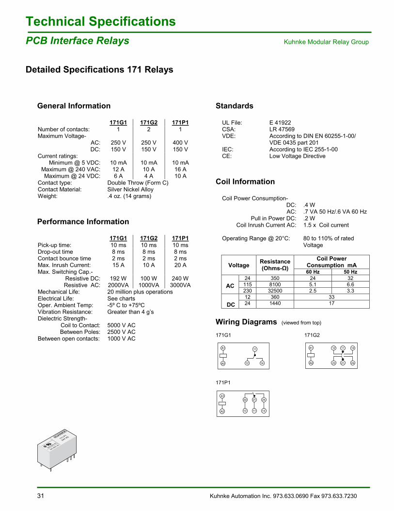
Detailed Specifications 171 Relays
General Information
171G1 171G2 171P1Number of contacts: 1 2 1Maximum Voltage-
AC: 250 V 250 V 400 VDC: 150 V 150 V 150 V
Current ratings:Minimum @ 5 VDC: 10 mA 10 mA 10 mA
Maximum @ 240 VAC: 12 A 10 A 16 AMaximum @ 24 VDC: 6 A 4 A 10 A
Contact type: Double Throw (Form C)Contact Material: Silver Nickel AlloyWeight: .4 oz. (14 grams)
Performance Information
171G1 171G2 171P1Pick-up time: 10 ms 10 ms 10 msDrop-out time 8 ms 8 ms 8 msContact bounce time 2 ms 2 ms 2 msMax. Inrush Current: 15 A 10 A 20 AMax. Switching Cap.-
Resistive DC: 192 W 100 W 240 WResistive AC: 2000VA 1000VA 3000VA
Mechanical Life: 20 million plus operationsElectrical Life: See chartsOper. Ambient Temp: -5º C to +75ºCVibration Resistance: Greater than 4 g�’sDielectric Strength-
Coil to Contact: 5000 V ACBetween Poles: 2500 V AC
Between open contacts: 1000 V AC
Standards
UL File: E 41922CSA: LR 47569VDE: According to DIN EN 60255-1-00/
VDE 0435 part 201IEC: According to IEC 255-1-00CE: Low Voltage Directive
Coil Information
Coil Power Consumption-DC: .4 WAC: .7 VA 50 Hz/.6 VA 60 Hz
Pull in Power DC: .2 WCoil Inrush Current AC: 1.5 x Coil current
Operating Range @ 20°C: 80 to 110% of ratedVoltage
Coil PowerConsumption mAVoltage Resistance
(Ohms- ) 60 Hz 50 Hz24 350 24 32115 8100 5.1 6.6AC230 32500 2.5 3.312 360 33
DC 24 1440 17
Wiring Diagrams (viewed from top)
171G1 171G2
171P1
171-P1
24V AC
16A 250V AC
16A 250V AC
REL171P1_ P.eps
REL_171G1_SB.eps
A1
A2 12
11
14
REL_171G2_SB.eps
12 11 14
22 21 24
A1
A2
REL_171P1_SB.eps
12 11 14
A1
A2
22 21 24
Kuhnke Automation Inc. 973.633.7230 Fax 973.633.7230 32
Technical SpecificationsKuhnke Modular Relay Group PCB Interface Relays
Detailed Specifications 171 Relays
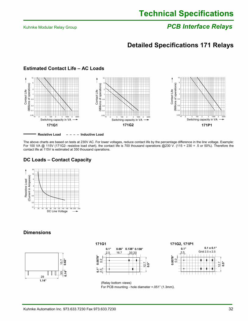
Estimated Contact Life �– AC Loads
Resistive Load �– �– �– �– Inductive Load
The above charts are based on tests at 230V AC. For lower voltages, reduce contact life by the percentage difference in the line voltage. Example:For 100 VA @ 115V (171G2- resistive load chart), the contact life is 700 thousand operations @230 V. (115 ÷ 230 = .5 or 50%). Therefore thecontact life at 115V is estimated at 350 thousand operations.
DC Loads �– Contact Capacity
Dimensions
171G1 171G2, 171P1
(Relay bottom views)For PCB mounting - hole diameter =.051�” (1.3mm).
Con
tact
Life
(Mill
ions
of o
pera
tions
)
Switching capacity in VA10
0.05
0.2
0.5
0.1
1
10
2
5
2 5 2 5 2 5000100 1000
Rel_171G1_Dia1_US.eps
Con
tact
Life
(Mill
ions
of o
pera
tions
)
Switching capacity in VA10
0.05
0.2
0.5
0.1
1
10
2
5
2 5 2 5 2 5000100 1000
Rel_171G2_Dia1_US.eps
Con
tact
Life
(Mill
ions
of o
pera
tions
)
Switching capacity in VA10
0.05
0.2
0.5
0.1
1
10
2
5
2 5 2 5 2 5000100 1000
Rel_171P1_Dia1_US.eps
20 40 60 80 100 120 140 160 220180 20000,1
0,5
1
0,2
5
10
20
2
Res
istiv
e Lo
ad(C
urre
nt in
Am
pere
s)
DC Line Voltage
Rel_171G1_Dia2_US.eps
NT.eps
29
15.7
3.5
0.62
"0.
14"
1.14"
2,5
3,5 3,516,7
12,70,
2
2,5
15,7
3,5
2.5
3.5 3.516.7
12.70.
2
2.5
15.7
3.5
0.66"0.1" 0.138" 0.138"
0.1"
0.00
78"
0.5"
0.62
".1
4"
171G1 171G2 171P1
12,70,
2
2,5
29
15,7
3,5
12.70.
2
2.5
29
15.7
3.5
Grid 2.5 x 2.5 Grid 2.5 x 2.50.1 x 0.1"0.1"
0.00
78"
0.5"

33 Kuhnke Automation Inc. 973.633.0690 Fax 973.633.7230
Other Relay Product Families:
105 Relay/Contactors with mechanically guidedcontacts for small motor applications. For socket orprinted circuit board mounting.
130 Octal socket timing relays available in severalversions.
C Electromechanical and solid state rail mountedinterface relays.
E Mechanically Interlocked Relays, dual coils withwalking beam construction, 6 Amp. 250V. forsocket or PCB mounting.
0135
0135
F Impulse latching Relays. Pulses of 50ms or morelatches or unlatches relay contacts. For socket orPCB mounting, 6 Amp. 250V. rating.
24V P
FA2Made in Germany
I Industrial relays up to 8 contacts (6A, 400V).Versions include mechanically guided contacts forhigh shock applications, DC blow out magnets andhigh capacity switching.
MF For current monitoring applications or for switchinghigher voltages (400V). Used in marine or airportnavigation systems.
P Open type single pole 50 Amp. power relayavailable with several contact materials and DCblowout magnets. For surface mounting.
PCB Family of Printed Circuit Board relays rated 5 to 15Amperes, up to 400V AC and available in severalcontact configurations.
PZ Process relays for converting analog and digitalsignals.
U500U1500
Monitoring relays including voltage, current, threephase out of step, and motor protection.
Relays by Catalog type
105A, 105G107109*, 110*111A, 111B, 111H, 111G114A117*,119*130135A*138*, 139*150*152171, 173, 174, 175, 176, 178C, CB*, CD, C-T*EB, EGF1570, FE17*FA, FGFR*HA , HF, HGI1540IA, IC, IG, IR, IX, IYIA2, IK2 Timers*ID*, IE*IF-D*IH100KC*, KH*, KB*, KG*LV*, LH*MA, MG*MFNA*, NF*PZPA, PRRB*, RE, RG*RH100*RS-xxxx Special Relays- see belowSB*SD5*U15, UD15U2Tr-K*U5UAUB, UFUD1*, UG1*, UW*UT*, UH*, UG*Zxxx- Relay Accessories
* - Obsolete
Special Relays
Kuhnke manufactures relays forspecial applications. These relays canbe a modification of any standard typerelay listed above. Special relayshave an identification mark �– RS (forRelay-Special) followed by a 4-digitfile number (example: RS-7131).Special relays are non-stock andmade to order.
KUHNKE ...IMPULSES FORAUTOMATION.
Kuhnke Automation Inc.P.O. Box 1369Wayne, NJ 07474-1369
Phone: 973-633-0690Fax: 973-633-7230email: [email protected]: www.kuhnkeusa.com 06
/12/
01/D
D P
rinte
d in
Ger
man
y
by
Kuhn
ke, B
ad M
alen
te-G
rem
smüh
len