Embed Size (px)
Citation preview
Contents
2
Contents
General dataPerformance range 50 and 60 Hz page 4Applications page 5Standard pumps page 5Pumped liquids page 5Construction page 5Motor page 5Operating conditions page 5BM types and versions page 6Sectional drawings page 6
Technical dataMaterials page 7Type key page 8Installation page 8Connections page 8Limitations to operation page 9Automatic control devices page 9Checking of operation page 9Performance data page 9
Performance curves, 60 HzBM 3A page 10BM 5A page 11BM 8A page 12BM 17 page 13BM 30 page 14BM 46 page 15BM 60 page 16BM 77 page 17BM 95 page 18BM 125 page 19
Order data, 60 HzBooster module 4", 3 x 440 - 480 V, 60 Hz,(with straight pipe connections) page 20Booster module 4", 3 x 575 V, 60 Hz,(with straight pipe connections) page 21Booster module 4", 3 x 440 - 480 V, 60 Hz,(with elbow) page 22Booster module 6", 3 x 440 - 480 V, 60 Hz,(with straight pipe connections) page 23Booster module 6", 3 x 575 V, 60 Hz,(with straight pipe connections) page 24Booster module 8", 3 x 440 - 480 V, 60 Hz, (with straight pipe connections) page 25Booster module 8", 3 x 575 V, 60 Hz,(with straight pipe connections) page 26
Performance curves, 50 HzBM 3A page 27BM 5A page 28BM 8A page 29BM 17 page 30BM 30 page 31BM 46 page 32BM 60 page 33BM 77 page 34BM 95 page 35BM 125 page 36
Order data, 50 HzBooster module 4", 3 x 380 - 415 V, 50 Hz,(with straight pipe connections) page 37Booster module 4", 3 x 380 - 415 V, 50 Hz,(with elbow) page 38Booster module 6", 3 x 380 - 415 V, 50 Hz,(with straight pipe connections) page 39Booster module 8", 3 x 380 - 415 V, 50 Hz,(with straight pipe connections) page 40
AccessoriesCU 3 Motor protection page 41MTP 75 motor protection page 43G100 page 44BM 4" page 46BM 6" and BM 8" page 47
Customizing your pumpCustom-made pumps page 48
Submittal data sheet page 49
Quotation text page 51

3
Mission
GBJ - Bjerringbro, Denmark
GMU - Fresno, California GPU - Olathe, Kansas
GMX - Monterrey, Mexico GPA - Allentown, Pennsylvania GCA - Oakville, Ontario
- to successfully develop, produce, and sell high quality pumps and pumping systems worldwide, contributing to a better quality of life and healthier environment
• One of the 3 largest pump companies in the world
• World headquarters in Denmark
• North American headquarters in Kansas City - Manufacturing in Fresno, California
• 60 companies in 40 countries
• More than 10 million pumps produced annually worldwide
• North American companies operating in USA, Canada and Mexico
• Continuous reinvestment in growth and development enables the company to
BE responsible, THINK ahead, and INNOVATE

4
Performance range, 60 Hz
Performance range, 50 Hz
TK0
1 12
32 3
7021 2 4 6 8 1010 20 40 60 80 100100 200 400Q [m³/h]
10
20
40
60
80
100
200
400
H[m]
5 7.5 10 25 50 75 100 250 500 750 1000Q [US GPM]
40
60
80
100
200
400
600
800
1000
H[ft]
60 Hz
BM
215
BM
160
BM
125
BM
95
BM
60
BM
77
BM
46
BM
30
BM
17
BM
8A
BM
5A
BM
3A
BM 4"
BM 6"
BM 8"
TK0
1 12
30 3
702P
erfo
rman
ce r
ange
50
Hz
and
60
Hz
10.8 11 2 4 6 8 1010 20 40 60 80 100100 200 400Q [m³/h]
10
20
40
100
200
400
H[m]
5 7.5 10 25 50 75 100 250 500 750 1000Q [US GPM]
40
60
80
100
200
400
600
800
1000
H[ft]
50 Hz
BM
215
BM
160
BM
125
BM
95
BM
60
BM
77
BM
30
BM
46
BM
17
BM
8A
BM
5A
BM
3A
BM 4"BM 6"
BM 8"
General data BM
5
General data BM
Applications
Introduction
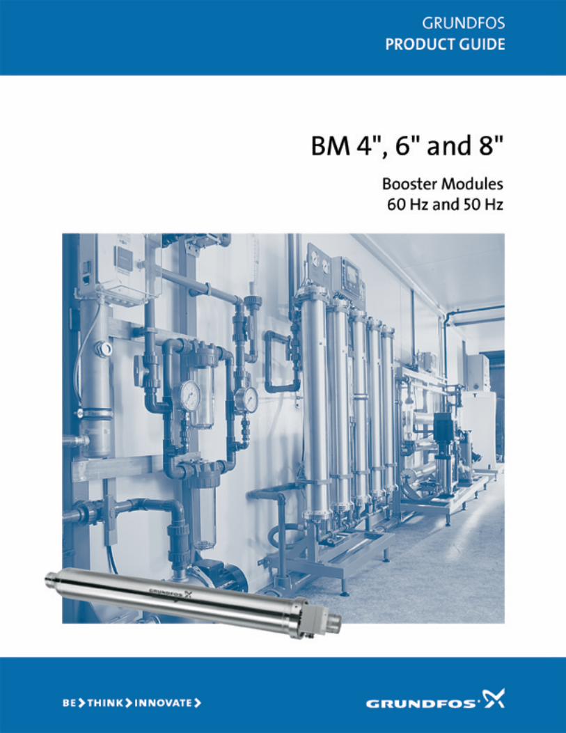
The Grundfos BM booster module is suitable for indus-trial and water supply applications requiring increasedsystem pressure.
The booster module is the optimum solution for applica-tions requiring ...
• sealless pumps,
• pumps capable of handling high system pressures,
• high heads,
• quiet operation,
• a minimum of maintenance.
Typical applications
BM booster modules are suitable for the followingtypical applications:
• Water treatment such as:- reverse osmosis in domestic water supply systems,
hospitals, laboratories, chemical, electronics andmetal industries.
- ultra-filtration in chemical and galvanic industries,painting workshops, metal and mineral industries.
• Liquid transfer.
• Pressure boosting.
• Closed circulation systems with a high static pres-sure.
Standard pumpsThe following standard pumps are available for the BMbooster modules:
• SP 3A, SP 5A and SP 8A in 4" sleeve.
• SP 17, SP 30, SP 46 and SP 60 in 6" sleeve.
• SP 30, SP 46, SP 60, SP 77, SP 95 and SP 125 in 8" sleeve.
Note: The BM booster modules are supplied withoutnon-return valves.
Pumped liquidsThin, non-explosive liquids not containing abrasiveparticles or fibers. The liquid must not attack the pumpmaterials chemically or mechanically.
If the density and/or viscosity of the pumped liquid ishigher than that of water, it may be necessary to usemotors with a higher output than the standard outputstated.
ConstructionModified standard submersible pumps are used for theBM booster modules. Pump and motor are centered inthe stainless steel sleeve.
Both sleeve ends can be connected to the piping bymeans of victaulic couplings.
A terminal box for electrical connection is placed at thedischarge end.
The sleeve of 4", 6" and 8" modules is supplied withstraight pipe inlet and outlet.
BM 4" is also available with 90° bends at the suction anddischarge ends.
MotorAsynchronous submersible squirrel-cage motor of thecanned type with water-lubricated bearings.
Voltages: 3 x 440-480 V +6/–10%, 60 Hz.3 x 575 V +6/-10%, 60 Hz.3 x 380-415 V +6/–10%, 50 Hz.
Enclosure class: IP 54/IP 58.Insulation class: B (for MS 4000).
F (for MS 6000 and Franklin 8").
Special versions: Other voltages are available onrequest.
Operating conditionsFlow: 60 Hz: Max. 335 m³/h, 1475 USGPM.
50 Hz: Max. 280 m³/h, 1233 USGPM.
Head: Max. 470 m/1542 ft.Higher performance is possible by connection in series or in parallel.
Temperature: Max. 40°C/104°F.(Contact Grundfos in case of higher temperature.)
Outletpressure: Max. 80 bar/1160 p.s.i.
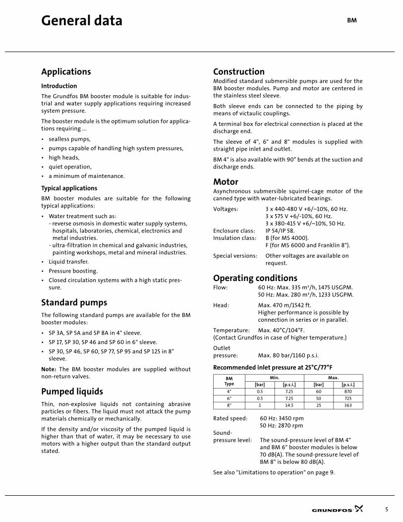
Recommended inlet pressure at 25°C/77°F
Rated speed: 60 Hz: 3450 rpm50 Hz: 2870 rpm
Sound-pressure level: The sound-pressure level of BM 4"
and BM 6" booster modules is below70 dB(A). The sound-pressure level ofBM 8" is below 80 dB(A).
See also "Limitations to operation" on page 9.
BMType
Min. Max.
[bar] [p.s.i.] [bar] [p.s.i.]
4" 0.5 7.25 60 870
6" 0.5 7.25 50 725
8" 1 14.5 25 363

6
General data BM
BM types and versions
BM 4" Straight version
BM 4" Elbow version
BM 6"
BM 8"
Sectional drawings
TM0
0 3
793
359
8TM
00
379
4 35
98
TM0
0 4
019
09
98
TM0
1 14
20 0
99
8
BM 4"TM
00
379
5 35
98
1. Sleeve
2. Discharge connection
3. Suction connection
4. Submersible motor
5. Submersible pump
6. Cable inlet
7. Terminal box
8. Inlet bypass valve
9. Locking system for BM 8".BM 4" and BM 6" have left-hand threadsfor locking.
BM 6"
TM0
0 3
796
359
8
BM 8"
TM0
1 14
19 3
598
7 8 5 4 3
12 9
2 7 8 5 4 3
16 9
2 5 4 3
1
7 8 9
7
Technical data BM
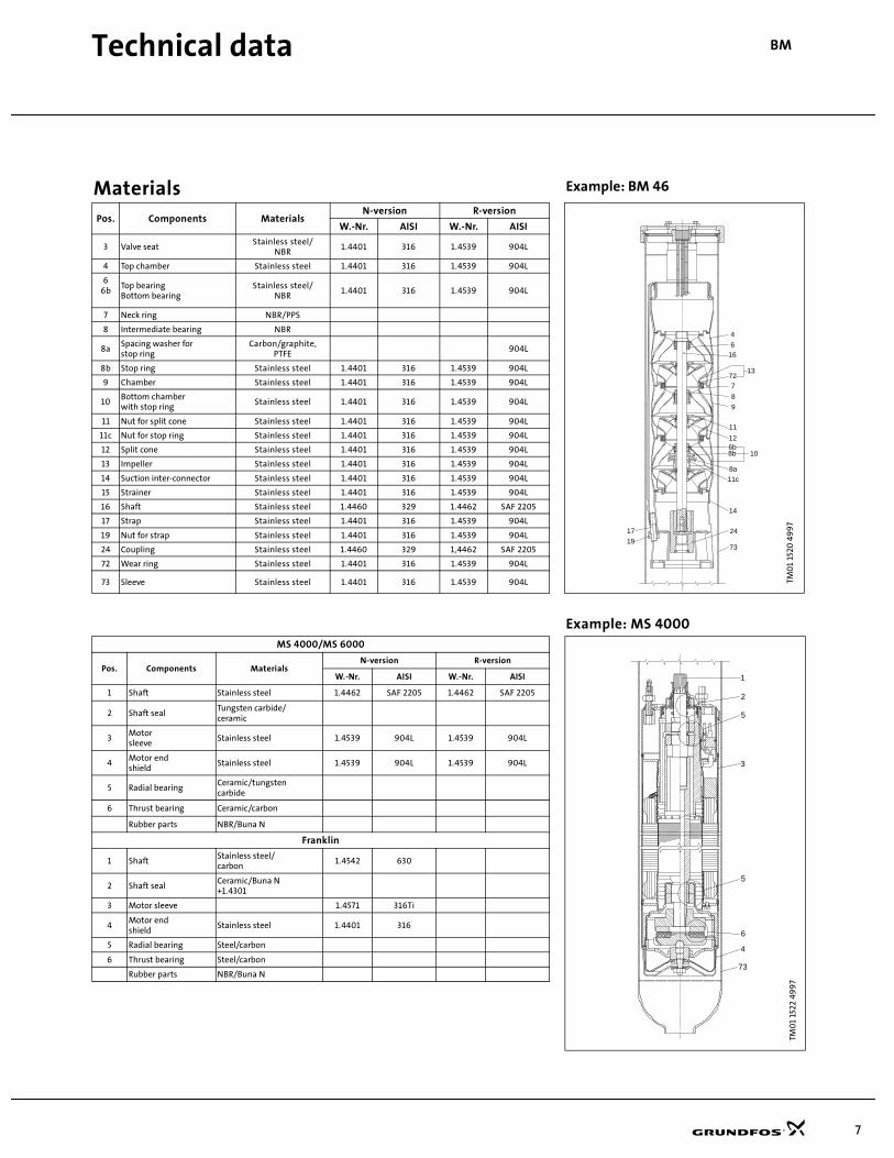
Materials Example: BM 46
Pos. Components MaterialsN-version R-version
TM0
1 15
20 4
99
7
W.-Nr. AISI W.-Nr. AISI
3 Valve seatStainless steel/
NBR1.4401 316 1.4539 904L
4 Top chamber Stainless steel 1.4401 316 1.4539 904L
66b
Top bearingBottom bearing
Stainless steel/NBR
1.4401 316 1.4539 904L
7 Neck ring NBR/PPS
8 Intermediate bearing NBR
8aSpacing washer for stop ring
Carbon/graphite,PTFE
904L
8b Stop ring Stainless steel 1.4401 316 1.4539 904L
9 Chamber Stainless steel 1.4401 316 1.4539 904L
10Bottom chamber with stop ring
Stainless steel 1.4401 316 1.4539 904L
11 Nut for split cone Stainless steel 1.4401 316 1.4539 904L
11c Nut for stop ring Stainless steel 1.4401 316 1.4539 904L
12 Split cone Stainless steel 1.4401 316 1.4539 904L
13 Impeller Stainless steel 1.4401 316 1.4539 904L
14 Suction inter-connector Stainless steel 1.4401 316 1.4539 904L
15 Strainer Stainless steel 1.4401 316 1.4539 904L
16 Shaft Stainless steel 1.4460 329 1.4462 SAF 2205
17 Strap Stainless steel 1.4401 316 1.4539 904L
19 Nut for strap Stainless steel 1.4401 316 1.4539 904L
24 Coupling Stainless steel 1.4460 329 1,4462 SAF 2205
72 Wear ring Stainless steel 1.4401 316 1.4539 904L
73 Sleeve Stainless steel 1.4401 316 1.4539 904L
Example: MS 4000MS 4000/MS 6000
Pos. Components MaterialsN-version R-version
W.-Nr. AISI W.-Nr. AISI
1 Shaft Stainless steel 1.4462 SAF 2205 1.4462 SAF 2205
2 Shaft sealTungsten carbide/ceramic
3Motor sleeve
Stainless steel 1.4539 904L 1.4539 904L
4Motor endshield
Stainless steel 1.4539 904L 1.4539 904L
5 Radial bearingCeramic/tungsten carbide
6 Thrust bearing Ceramic/carbon
Rubber parts NBR/Buna N
Franklin
1 ShaftStainless steel/carbon
1.4542 630
2 Shaft sealCeramic/Buna N+1.4301
TM0
1 15
22 4
99
7
3 Motor sleeve 1.4571 316Ti
4Motor endshield
Stainless steel 1.4401 316
5 Radial bearing Steel/carbon
6 Thrust bearing Steel/carbon
Rubber parts NBR/Buna N
8b6b
16
17
10
24
11c
8a
1372
14
19
7
12
8
11
9
6
4
73
2
5
5
6
4
3
1
73
8
Technical data BM
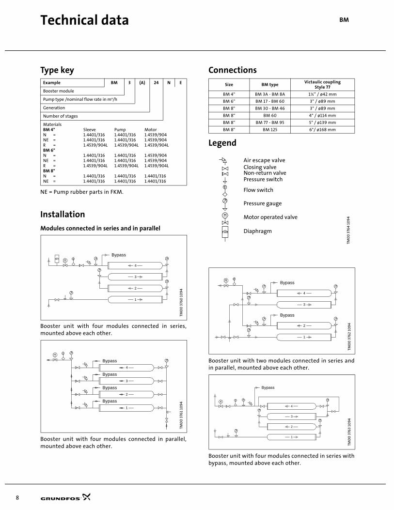
Type key
NE = Pump rubber parts in FKM.
Installation
Modules connected in series and in parallel
Booster unit with four modules connected in series,mounted above each other.
Booster unit with four modules connected in parallel,mounted above each other.
Connections
Legend
Booster unit with two modules connected in series andin parallel, mounted above each other.
Booster unit with four modules connected in series withbypass, mounted above each other.
Example BM 3 (A) 24 N E
Booster module
Pump type /nominal flow rate in m³/h
Generation
Number of stages
MaterialsBM 4" Sleeve Pump MotorN = 1.4401/316 1.4401/316 1.4539/904NE = 1.4401/316 1.4401/316 1.4539/904R = 1.4539/904L 1.4539/904L 1.4539/904LBM 6"N = 1.4401/316 1.4401/316 1.4539/904NE = 1.4401/316 1.4401/316 1.4539/904R = 1.4539/904L 1.4539/904L 1.4539/904LBM 8"N = 1.4401/316 1.4401/316 1.4401/316NE = 1.4401/316 1.4401/316 1.4401/316
TM0
0 3
760
10
94
TM0
0 3
761
109
4
Bypass
1
2
3
4
Bypass
Bypass
Bypass
Bypass
1
2
3
4
Size BM typeVictaulic coupling
Style 77
BM 4" BM 3A - BM 8A 1¼” / ø42 mm
BM 6" BM 17 - BM 60 3" / ø89 mm
BM 8" BM 30 - BM 46 3" / ø89 mm
BM 8" BM 60 4" / ø114 mm
BM 8" BM 77 - BM 95 5" / ø139 mm
BM 8" BM 125 6"/ ø168 mm
TM0
0 3
764
109
4TM
00
376
2 10
94
TM0
0 3
763
109
4
Air escape valveClosing valveNon return valvePressure switch
Flow switch
Motor operated valve
Diaphragm tank
Pressure gauge
Closing valveNon-return valvePressure switch
Flow switch
Pressure gauge
Motor operated valve
Diaphragm
Air escape valve
Bypass
Bypass
1
2
3
4
Bypass
1
2
3
4
9
Technical data BM
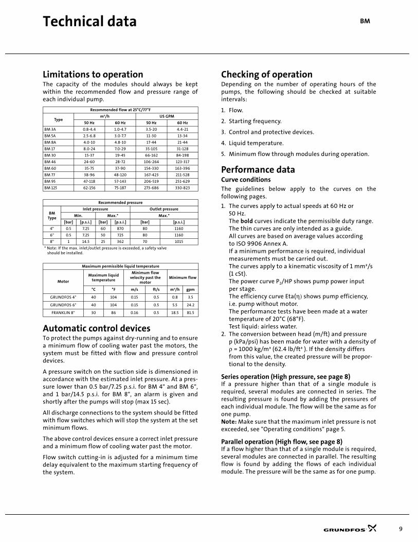
Limitations to operationThe capacity of the modules should always be keptwithin the recommended flow and pressure range ofeach individual pump.
Automatic control devicesTo protect the pumps against dry-running and to ensurea minimum flow of cooling water past the motors, thesystem must be fitted with flow and pressure controldevices.
A pressure switch on the suction side is dimensioned inaccordance with the estimated inlet pressure. At a pres-sure lower than 0.5 bar/7.25 p.s.i. for BM 4" and BM 6",and 1 bar/14.5 p.s.i. for BM 8", an alarm is given andshortly after the pumps will stop (max 15 sec).
All discharge connections to the system should be fittedwith flow switches which will stop the system at the setminimum flows.
The above control devices ensure a correct inlet pressureand a minimum flow of cooling water past the motor.
Flow switch cutting-in is adjusted for a minimum timedelay equivalent to the maximum starting frequency ofthe system.
Checking of operationDepending on the number of operating hours of thepumps, the following should be checked at suitableintervals:
1. Flow.
2. Starting frequency.
3. Control and protective devices.
4. Liquid temperature.
5. Minimum flow through modules during operation.
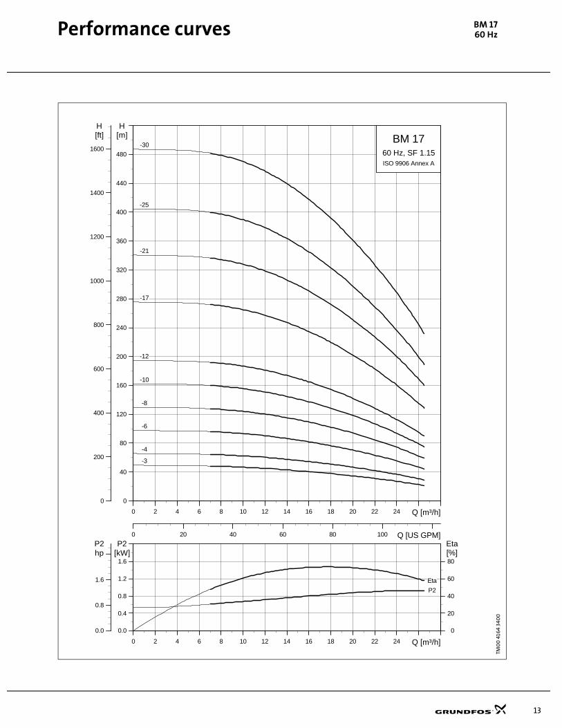
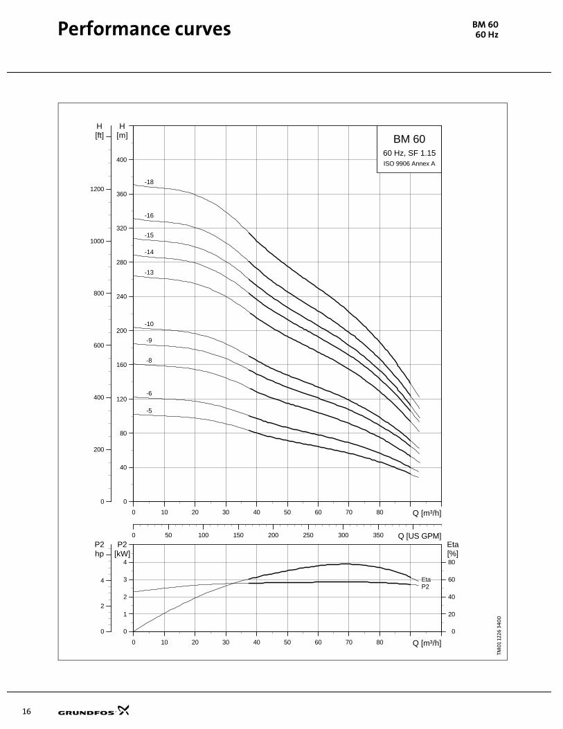
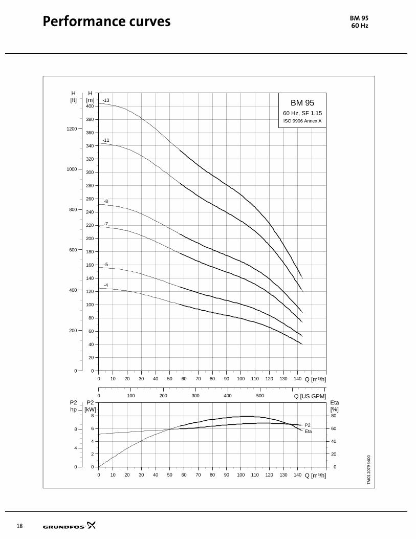
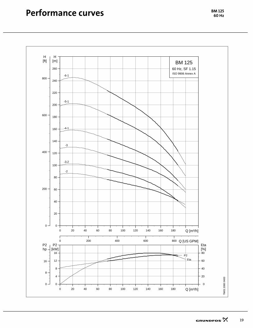
Performance dataCurve conditionsThe guidelines below apply to the curves on thefollowing pages.
1. The curves apply to actual speeds at 60 Hz or50 Hz.The bold curves indicate the permissible duty range.The thin curves are only intended as a guide.All curves are based on average values according to ISO 9906 Annex A.If a minimum performance is required, individualmeasurements must be carried out.The curves apply to a kinematic viscosity of 1 mm²/s (1 cSt).The power curve P2/HP shows pump power input per stage.The efficiency curve Eta(η) shows pump efficiency, i.e. pump without motor.The performance tests have been made at a watertemperature of 20°C (68°F).Test liquid: airless water.
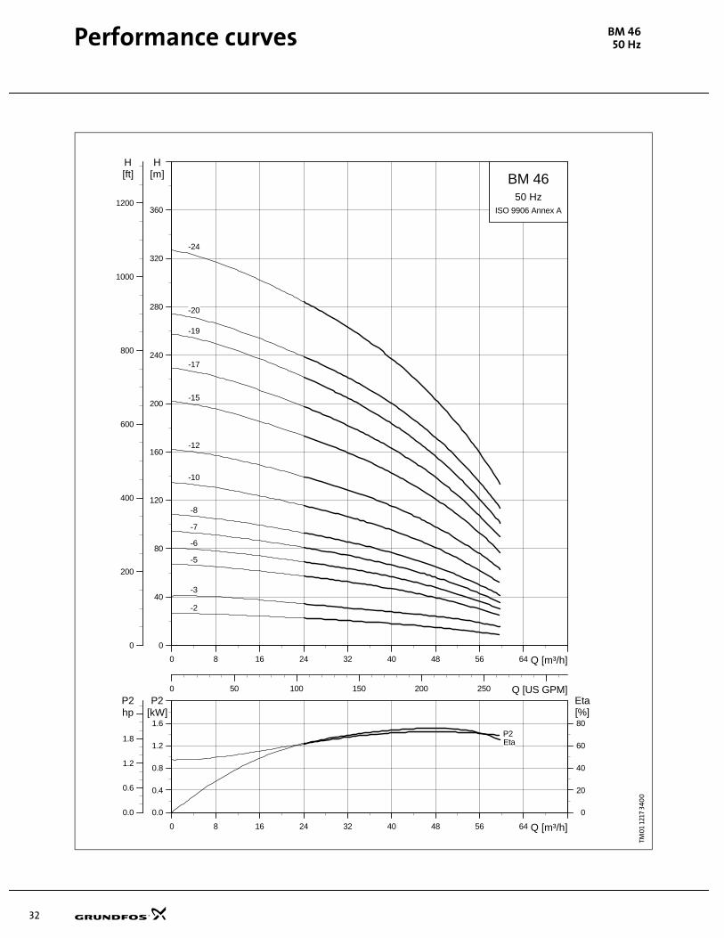
2. The conversion between head (m/ft) and pressurep (kPa/psi) has been made for water with a density ofρ = 1000 kg/m³ (62.4 lb/ft³ ). If the density differs from this value, the created pressure will be propor-tional to the density.
Series operation (High pressure, see page 8)If a pressure higher than that of a single module isrequired, several modules are connected in series. Theresulting pressure is found by adding the pressures ofeach individual module. The flow will be the same as forone pump.Note: Make sure that the maximum inlet pressure is notexceeded, see "Operating conditions" page 5.
Parallel operation (High flow, see page 8)If a flow higher than that of a single module is required,several modules are connected in parallel. The resultingflow is found by adding the flows of each individualmodule. The pressure will be the same as for one pump.
Recommended flow at 25°C/77°F
Typem³/h US GPM
50 Hz 60 Hz 50 Hz 60 Hz
BM 3A 0.8-4.4 1.0-4.7 3.5-20 4.4-21
BM 5A 2.5-6.8 3.0-7.7 11-30 13-34
BM 8A 4.0-10 4.8-10 17-44 21-44
BM 17 8.0-24 7.0-29 35-105 31-128
BM 30 15-37 19-45 66-162 84-198
BM 46 24-60 28-72 106-264 123-317
BM 60 35-75 37-90 154-330 163-396
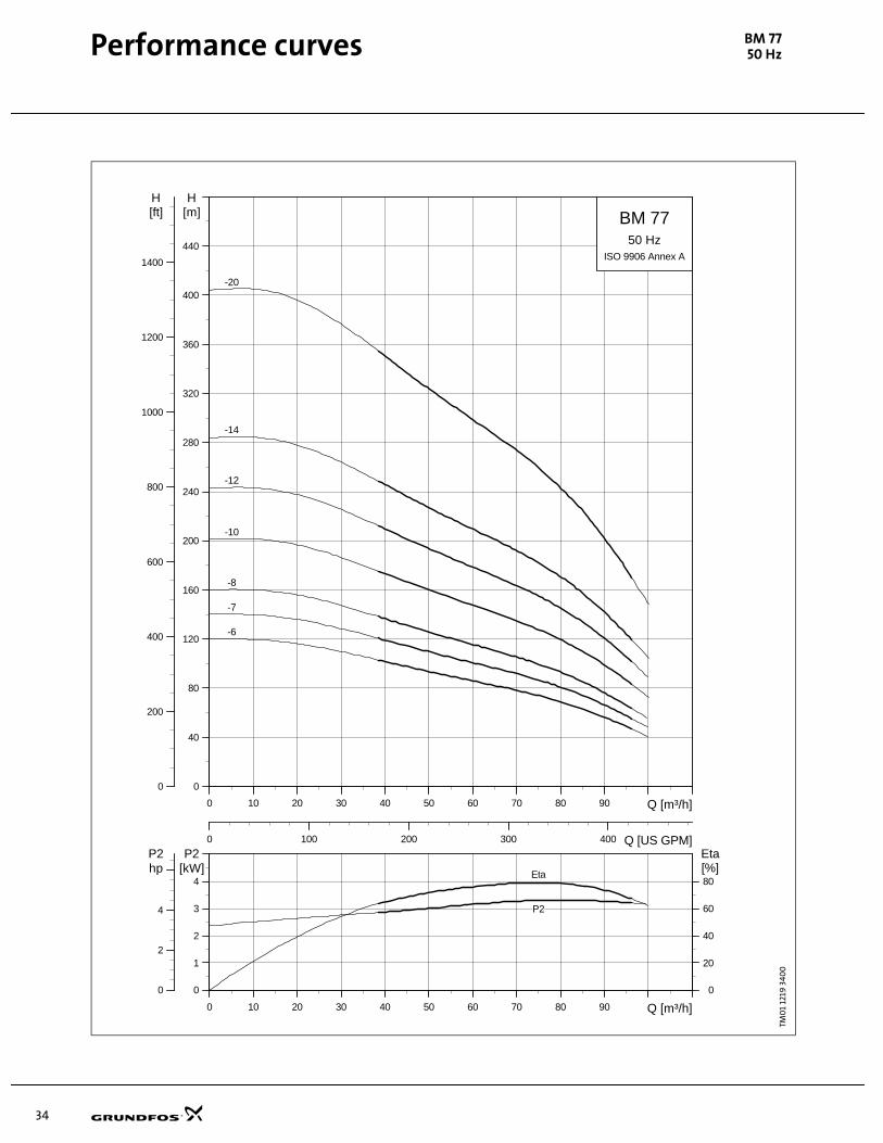
BM 77 38-96 48-120 167-423 211-528
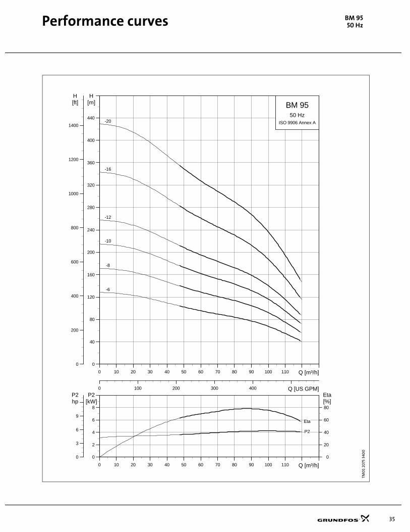
BM 95 47-118 57-143 206-519 251-629
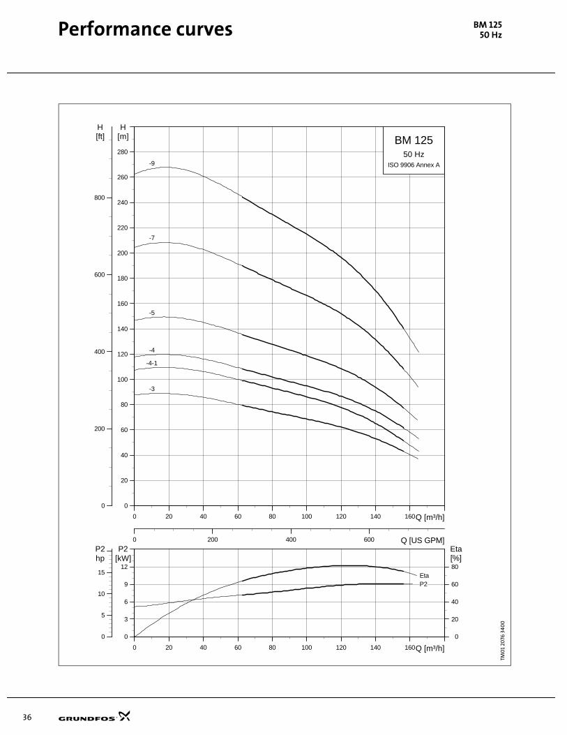
BM 125 62-156 75-187 273-686 330-823
Recommended pressure
BMType
Inlet pressure Outlet pressure
Min. Max.* Max.*
[bar] [p.s.i.] [bar] [p.s.i.] [bar] [p.s.i.]
4" 0.5 7.25 60 870 80 1160
6" 0.5 7.25 50 725 80 1160
8" 1 14.5 25 362 70 1015
* Note: If the max. inlet/outlet pressure is exceeded, a safety valveshould be installed.
Maximum permissible liquid temperature
Motor
Maximum liquidtemperature
Minimum flow velocity past the
motorMinimum flow
°C °F m/s ft/s m³/h gpm
GRUNDFOS 4" 40 104 0.15 0.5 0.8 3.5
GRUNDFOS 6" 40 104 0.15 0.5 5.5 24.2
FRANKLIN 8" 30 86 0.16 0.5 18.5 81.5
10
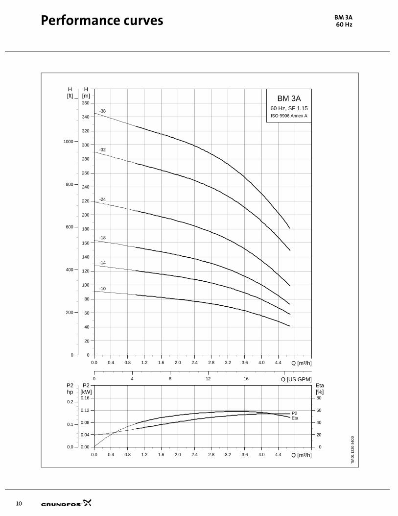
Performance curves BM 3A60 Hz
TM0
1 12
20 3
400Pe
rfo
rman
ce c
urv
es, 6
0 H
zBM
3A
0.0 0.4 0.8 1.2 1.6 2.0 2.4 2.8 3.2 3.6 4.0 4.4 Q [m³/h]
0.00
0.04
0.08
0.12
0.16
P2[kW]
0
20
40
60
80
Eta[%]
0.0
0.1
0.2
hpP2
EtaP2
0.0 0.4 0.8 1.2 1.6 2.0 2.4 2.8 3.2 3.6 4.0 4.4 Q [m³/h]
0
20
40
60
80
100
120
140
160
180
200
220
240
260
280
300
320
340
360
H[m]
0
200
400
600
800
1000
H[ft]
0 4 8 12 16 Q [US GPM]
BM 3A
ISO 9906 Annex A
60 Hz, SF 1.15
-10
-14
-18
-24
-32
-38
11
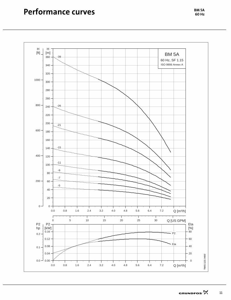
Performance curves BM 5A60 Hz
TM0
1 12
21 3
400
0.0 0.8 1.6 2.4 3.2 4.0 4.8 5.6 6.4 7.2 Q [m³/h]
0.00
0.04
0.08
0.12
0.16
P2[kW]
0
20
40
60
80
Eta[%]
0.0
0.1
0.2
hpP2
P2
0.0 0.8 1.6 2.4 3.2 4.0 4.8 5.6 6.4 7.2 Q [m³/h]
0
20
40
60
80
100
120
140
160
180
200
220
240
260
280
300
320
340
360
H[m]
0
200
400
600
800
1000
H[ft]
0 5 10 15 20 25 30 Q [US GPM]
BM 5A
ISO 9906 Annex A
60 Hz, SF 1.15
-11
-15
-26
-21
-39
-5
-7
-9
Eta
12
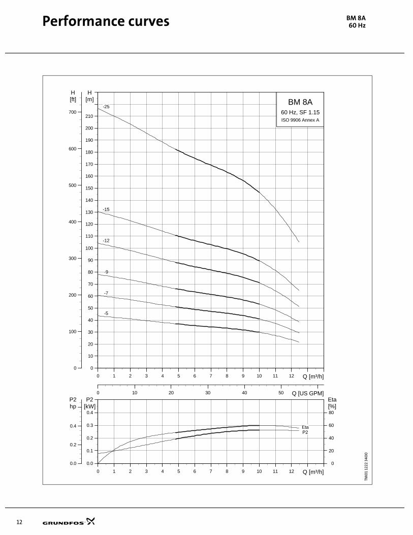
Performance curves BM 8A60 Hz
TM0
1 12
22 3
40
0
0 1 2 3 4 5 6 7 8 9 10 11 12 Q [m³/h]
0.0
0.1
0.2
0.3
0.4
P2[kW]
0
20
40
60
80
Eta[%]
0.0
0.2
0.4
hpP2
EtaP2
0 1 2 3 4 5 6 7 8 9 10 11 12 Q [m³/h]
0
10
20
30
40
50
60
70
80
90
100
110
120
130
140
150
160
170
180
190
200
210
H[m]
0
100
200
300
400
500
600
700
H[ft]
0 10 20 30 40 50 Q [US GPM]
BM 8A
ISO 9906 Annex A
60 Hz, SF 1.15
-12
-15
-25
-5
-7
-9
13
Performance curves BM 1760 Hz
TM0
0 4
164
34
00
0 2 4 6 8 10 12 14 16 18 20 22 24 Q [m³/h]
0.0
0.4
0.8
1.2
1.6
P2[kW]
0
20
40
60
80
Eta[%]
0.0
0.8
1.6
hpP2
Eta
P2
0 2 4 6 8 10 12 14 16 18 20 22 24 Q [m³/h]
0
40
80
120
160
200
240
280
320
360
400
440
480
H[m]
0
200
400
600
800
1000
1200
1400
1600
H[ft]
0 20 40 60 80 100 Q [US GPM]
BM 17
ISO 9906 Annex A
60 Hz, SF 1.15
-10
-12
-17
-21
-25
-3
-30
-4
-6
-8

14
Performance curves BM 3060 Hz
TK0
1 20
78 3
702
0 5 10 15 20 25 30 35 40 45 Q [m³/h]
0.0
0.4
0.8
1.2
1.6
P2[kW]
0
20
40
60
80
Eta[%]
0.0
0.8
1.6
hpP2
Eta
P2
0 5 10 15 20 25 30 35 40 45 Q [m³/h]
0
40
80
120
160
200
240
280
320
360
400
440
480
H[m]
0
200
400
600
800
1000
1200
1400
1600
H[ft]
0 40 80 120 160 200 Q [US GPM]
BM 30
ISO 9906 Annex A
60 Hz, SF 1.15
-10
-11
-14
-17
-2
-20
-23
-27
-3
-4
-5
-7
-8

15
Performance curves BM 4660 Hz
TM0
1 12
25 3
40
0
0 8 16 24 32 40 48 56 64 Q [m³/h]
0
1
2
3
4
P2[kW]
0
20
40
60
80
Eta[%]
0
2
4
hpP2
Eta
P2
0 8 16 24 32 40 48 56 64 Q [m³/h]
0
40
80
120
160
200
240
280
320
360
400
H[m]
0
200
400
600
800
1000
1200
H[ft]
0 50 100 150 200 250 Q [US GPM]
BM 46
ISO 9906 Annex A
60 Hz, SF 1.15
-11
-13
-16
-19
-2
-3
-4
-5
-6
-8
-9
16
Performance curves BM 6060 Hz
TM0
1 12
26 3
400
0 10 20 30 40 50 60 70 80 Q [m³/h]
0
1
2
3
4
P2[kW]
0
20
40
60
80
Eta[%]
0
2
4
hpP2
EtaP2
0 10 20 30 40 50 60 70 80 Q [m³/h]
0
40
80
120
160
200
240
280
320
360
400
H[m]
0
200
400
600
800
1000
1200
H[ft]
0 50 100 150 200 250 300 350 Q [US GPM]
BM 60
ISO 9906 Annex A
60 Hz, SF 1.15
-10
-13
-14
-15
-16
-18
-5
-6
-8
-9

17
Performance curves BM 7760 Hz
TM0
1 12
27 3
400
0 10 20 30 40 50 60 70 80 90 100 110 Q [m³/h]
0
2
4
6
8
P2[kW]
0
20
40
60
80
Eta[%]
0
4
8
hpP2
Eta
P2
0 10 20 30 40 50 60 70 80 90 100 110 Q [m³/h]
0
20
40
60
80
100
120
140
160
180
200
220
240
260
280
300
320
340
360
380
400
H[m]
0
200
400
600
800
1000
1200
H[ft]
0 100 200 300 400 Q [US GPM]
BM 77
ISO 9906 Annex A
60 Hz, SF 1.15
-10
-13
-4
-5
-6
-7
18
Performance curves BM 9560 Hz
TM0
1 20
79 3
400
0 10 20 30 40 50 60 70 80 90 100 110 120 130 140 Q [m³/h]
0
2
4
6
8
P2[kW]
0
20
40
60
80
Eta[%]
0
4
8
hpP2
EtaP2
0 10 20 30 40 50 60 70 80 90 100 110 120 130 140 Q [m³/h]
0
20
40
60
80
100
120
140
160
180
200
220
240
260
280
300
320
340
360
380
400
H[m]
0
200
400
600
800
1000
1200
H[ft]
0 100 200 300 400 500 Q [US GPM]
BM 95
ISO 9906 Annex A
60 Hz, SF 1.15
-11
-13
-4
-5
-7
-8
19
Performance curves BM 12560 Hz
TM0
1 20
80
340
0
0 20 40 60 80 100 120 140 160 180 Q [m³/h]
0
4
8
12
16
P2[kW]
0
20
40
60
80
Eta[%]
0
8
16
hpP2
Eta
P2
0 20 40 60 80 100 120 140 160 180 Q [m³/h]
0
20
40
60
80
100
120
140
160
180
200
220
240
260
H[m]
0
200
400
600
800
H[ft]
0 200 400 600 800 Q [US GPM]
BM 125
ISO 9906 Annex A
60 Hz, SF 1.15
-2
-3
-3-2
-4-1
-5-1
-6-1
20
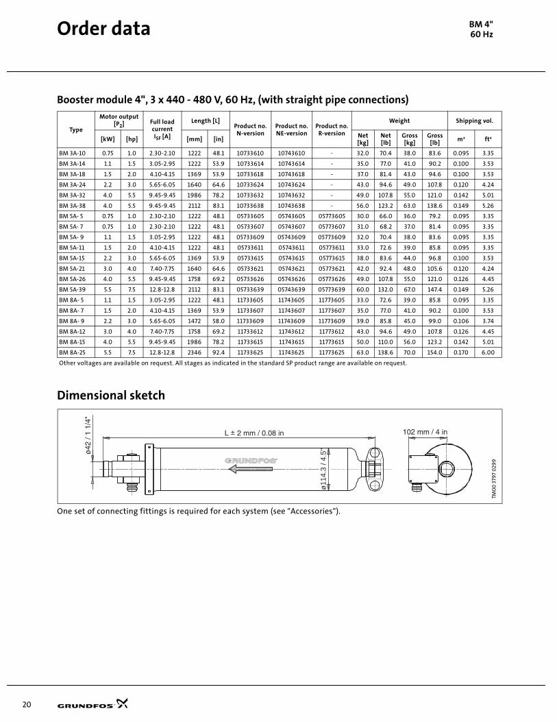
Order data BM 4"60 Hz
Booster module 4", 3 x 440 - 480 V, 60 Hz, (with straight pipe connections)
Dimensional sketch
One set of connecting fittings is required for each system (see "Accessories").
Type
Motor output[P2] Full load
currentISF [A]
Length [L]Product no.N-version
Product no.NE-version
Product no.R-version
Weight Shipping vol.
[kW] [hp] [mm] [in]Net[kg]
Net[lb]
Gross [kg]
Gross [lb]
m³ ft³
BM 3A-10 0.75 1.0 2.30-2.10 1222 48.1 10733610 10743610 - 32.0 70.4 38.0 83.6 0.095 3.35
BM 3A-14 1.1 1.5 3.05-2.95 1222 53.9 10733614 10743614 - 35.0 77.0 41.0 90.2 0.100 3.53
BM 3A-18 1.5 2.0 4.10-4.15 1369 53.9 10733618 10743618 - 37.0 81.4 43.0 94.6 0.100 3.53
BM 3A-24 2.2 3.0 5.65-6.05 1640 64.6 10733624 10743624 - 43.0 94.6 49.0 107.8 0.120 4.24
BM 3A-32 4.0 5.5 9.45-9.45 1986 78.2 10733632 10743632 - 49.0 107.8 55.0 121.0 0.142 5.01
BM 3A-38 4.0 5.5 9.45-9.45 2112 83.1 10733638 10743638 - 56.0 123.2 63.0 138.6 0.149 5.26
BM 5A- 5 0.75 1.0 2.30-2.10 1222 48.1 05733605 05743605 05773605 30.0 66.0 36.0 79.2 0.095 3.35
BM 5A- 7 0.75 1.0 2.30-2.10 1222 48.1 05733607 05743607 05773607 31.0 68.2 37.0 81.4 0.095 3.35
BM 5A- 9 1.1 1.5 3.05-2.95 1222 48.1 05733609 05743609 05773609 32.0 70.4 38.0 83.6 0.095 3.35
BM 5A-11 1.5 2.0 4.10-4.15 1222 48.1 05733611 05743611 05773611 33.0 72.6 39.0 85.8 0.095 3.35
BM 5A-15 2.2 3.0 5.65-6.05 1369 53.9 05733615 05743615 05773615 38.0 83.6 44.0 96.8 0.100 3.53
BM 5A-21 3.0 4.0 7.40-7.75 1640 64.6 05733621 05743621 05773621 42.0 92.4 48.0 105.6 0.120 4.24
BM 5A-26 4.0 5.5 9.45-9.45 1758 69.2 05733626 05743626 05773626 49.0 107.8 55.0 121.0 0.126 4.45
BM 5A-39 5.5 7.5 12.8-12.8 2112 83.1 05733639 05743639 05773639 60.0 132.0 67.0 147.4 0.149 5.26
BM 8A- 5 1.1 1.5 3.05-2.95 1222 48.1 11733605 11743605 11773605 33.0 72.6 39.0 85.8 0.095 3.35
BM 8A- 7 1.5 2.0 4.10-4.15 1369 53.9 11733607 11743607 11773607 35.0 77.0 41.0 90.2 0.100 3.53
BM 8A- 9 2.2 3.0 5.65-6.05 1472 58.0 11733609 11743609 11773609 39.0 85.8 45.0 99.0 0.106 3.74
BM 8A-12 3.0 4.0 7.40-7.75 1758 69.2 11733612 11743612 11773612 43.0 94.6 49.0 107.8 0.126 4.45
BM 8A-15 4.0 5.5 9.45-9.45 1986 78.2 11733615 11743615 11773615 50.0 110.0 56.0 123.2 0.142 5.01
BM 8A-25 5.5 7.5 12.8-12.8 2346 92.4 11733625 11743625 11773625 63.0 138.6 70.0 154.0 0.170 6.00
Other voltages are available on request. All stages as indicated in the standard SP product range are available on request.
TM0
0 3
797
029
9
ø11
4.3
/ 4.5
"

21
Order data BM 4"60 Hz
Booster module 4", 3 x 575 V, 60 Hz, (with straight pipe connections)*
Dimensional sketch
One set of connecting fittings is required for each system (see "Accessories").
Type
Motor output[P2] Full load
currentISF [A]
Length [L]Product no.N-version
Product no.NE-version
Product no.R-version
Weight Shipping vol.
[kW] [hp] [mm] [in]Net[kg]
Net[lb]
Gross [kg]
Gross [lb]
m³ ft³
BM 3A-10 0.75 1.0 1.76 1222 48.1 10733910 10743910 - 32.0 70.4 38.0 83.6 0.095 3.35
BM 3A-14 1.1 1.5 2.40 1222 53.9 10733914 10743914 - 35.0 77.0 41.0 90.2 0.100 3.53
BM 3A-18 1.5 2.0 3.25 1369 53.9 10733918 10743918 - 37.0 81.4 43.0 94.6 0.100 3.53
BM 3A-24 2.2 3.0 4.65 1640 64.6 10733924 10743924 - 43.0 94.6 49.0 107.8 0.120 4.24
BM 3A-32 4.0 5.0 6.90 1986 78.2 10733932 10743932 - 49.0 107.8 55.0 121.0 0.142 5.01
BM 3A-38 4.0 7.5 10.0 2112 83.1 10733938 10743938 - 56.0 123.2 63.0 138.6 0.149 5.26
BM 5A- 5 0.75 1.0 1.76 1222 48.1 05733905 05743905 call factory 30.0 66.0 36.0 79.2 0.095 3.35
BM 5A- 7 0.75 1.0 1.76 1222 48.1 05733907 05743907 call factory 31.0 68.2 37.0 81.4 0.095 3.35
BM 5A- 9 1.1 1.5 2.40 1222 48.1 05733909 05743909 call factory 32.0 70.4 38.0 83.6 0.095 3.35
BM 5A-11 1.5 2.0 3.25 1222 48.1 05733911 05743911 call factory 33.0 72.6 39.0 85.8 0.095 3.35
BM 5A-15 2.2 3.0 4.65 1369 53.9 05733915 05743915 call factory 38.0 83.6 44.0 96.8 0.100 3.53
BM 5A-21 3.0 7.5 10.0 1640 64.6 05733921 05743921 call factory 42.0 92.4 48.0 105.6 0.120 4.24
BM 5A-26 4.0 5.0 6.90 1758 69.2 05733926 05743926 call factory 49.0 107.8 55.0 121.0 0.126 4.45
BM 5A-39 5.5 7.5 10.0 2112 83.1 05733939 05743939 call factory 60.0 132.0 67.0 147.4 0.149 5.26
BM 8A- 5 1.1 1.5 2.40 1222 48.1 11733905 11743905 call factory 33.0 72.6 39.0 85.8 0.095 3.35
BM 8A- 7 1.5 2.0 3.25 1369 53.9 11733907 11743907 call factory 35.0 77.0 41.0 90.2 0.100 3.53
BM 8A- 9 2.2 3.0 4.65 1472 58.0 11733909 11743909 call factory 39.0 85.8 45.0 99.0 0.106 3.74
BM 8A-12 3.0 5.0 6.90 1758 69.2 11733912 11743912 call factory 43.0 94.6 49.0 107.8 0.126 4.45
BM 8A-15 4.0 7.5 10.0 1986 78.2 11733915 11743915 call factory 50.0 110.0 56.0 123.2 0.142 5.01
BM 8A-25 5.5 7.5 10.0 2346 92.4 11733925 11743925 call factory 63.0 138.6 70.0 154.0 0.170 6.00
Other voltages are available on request. All stages as indicated in the standard SP product range are available on request.
*Booster Module 4”, 3 x 575 V, 60 Hz, (with elbow), available on request.
TM0
0 3
797
029
9
ø11
4.3
/ 4.5
"

22
Order data BM 4"60 Hz
Booster module 4", 3 x 440 - 480 V, 60 Hz, (with elbow)*
Dimensional sketch
One set of connecting fittings is required for each system (please see "Accessories").
Type
Motor output[P2] Full load
currentISF [A]
Length [L]Product no.N-version
Product no.NE-version
Weight Shipping vol.
[kW] [hp] [mm] [in]Net[kg]
Net[lb]
Gross [kg]
Gross [lb]
m³ ft³
BM 3A-10 0.75 1.0 2.30-2.10 1144 45.0 10753610 10763610 32.0 70.4 38.0 83.6 0.100 3.53
BM 3A-14 1.1 1.5 3.05-2.95 1291 50.8 10753614 10763614 35.0 77.0 41.0 90.2 0.100 3.53
BM 3A-18 1.5 2.0 4.10-4.15 1291 50.8 10753618 10763618 37.0 81.4 43.0 94.6 0.120 4.24
BM 3A-24 2.2 3.0 5.65-6.05 1562 61.5 10753624 10763624 43.0 94.6 49.0 107.8 0.142 5.02
BM 3A-32 3.0 4.0 7.40-7.75 1908 75.1 10753632 10763632 49.0 107.8 55.0 121.0 0.149 5.26
BM 3A-38 4.0 5.5 9.45-9.45 2034 80.1 10753638 10763638 56.0 123.2 63.0 138.6 0.095 3.35
BM 5A-5 0.75 1.0 2.30-2.10 1144 45.0 05753605 05763605 30.0 66.0 36.0 79.2 0.095 3.35
BM 5A-7 0.75 1.0 2.30-2.10 1144 45.0 05753607 05763607 31.0 68.2 37.0 81.4 0.095 3.35
BM 5A-9 1.1 1.5 3.05-2.95 1144 45.0 05753609 05763609 32.0 70.4 38.0 83.6 0.095 3.35
BM 5A-11 1.5 2.0 4.10-4.15 1144 45.0 05753611 05763611 33.0 72.6 39.0 85.8 0.100 3.53
BM 5A-15 2.2 3.0 5.65-6.05 1291 50.8 05753615 05763615 38.0 83.6 44.0 96.8 0.120 4.24
BM 5A-21 3.0 4.0 7.40-7.75 1562 61.5 05753621 05763621 42.0 92.4 48.0 105.6 0.126 4.45
BM 5A-26 4.0 5.5 9.45-9.45 1680 66.1 05753626 05763626 49.0 107.8 55.0 121.0 0.149 5.26
BM 5A- 39 5.5 7.5 12.8-12.8 2034 80.1 05753639 05763639 60.0 132.0 67.0 147.4 0.095 3.35
BM 8A-5 1.1 1.5 3.05-2.95 1144 45.0 11753605 11763605 33.0 72.6 39.0 85.8 0.100 3.53
BM 8A-7 1.5 2.0 4.10-4.15 1291 50.8 11753607 11763607 35.0 77.0 41.0 90.2 0.106 3.74
BM 8A-9 2.2 3.0 5.65-6.05 1394 54.9 11753609 11763609 39.0 85.8 45.0 99.0 0.126 4.45
BM 8A-12 3.0 4.0 7.40-7.75 1680 66.1 11753612 11763612 43.0 94.6 49.0 107.8 0.142 5.02
BM 8A-15 4.0 5.5 9.45-9.45 1908 75.1 11753615 11763615 50.0 110.0 56.0 123.2 0.170 6.00
BM 8A-25 5.5 7.5 12.8-12.8 2268 89.3 11753625 11763625 63.0 138.6 70.0 154.0 0.100 3.53
Other voltages are available on request. All stages as indicated in the standard SP product range are available on request.
*Booster Module 4”, 3 x 575 V, 60 Hz, (with elbow), available on request.
TM0
0 3
798
029
9
ø11
4.3
/ 4.5
"
23
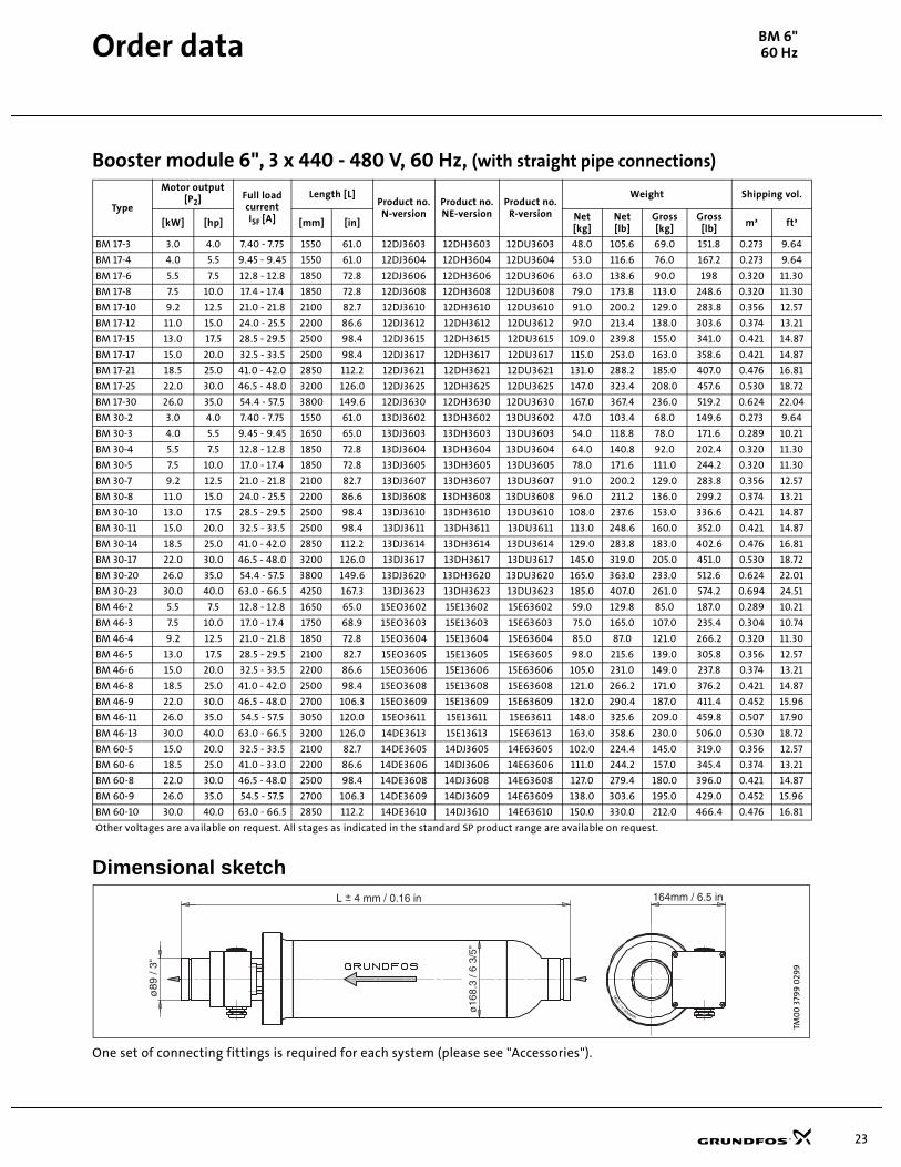
BM 6"60 Hz
Booster module 6", 3 x 440 - 480 V, 60 Hz, (with straight pipe connections)
Dimensional sketch
One set of connecting fittings is required for each system (please see "Accessories").
Type
Motor output[P2] Full load
currentISF [A]
Length [L]Product no.N-version
Product no.NE-version
Product no.R-version
Weight Shipping vol.
[kW] [hp] [mm] [in]Net[kg]
Net[lb]
Gross [kg]
Gross [lb]
m³ ft³
BM 17-3 3.0 4.0 7.40 - 7.75 1550 61.0 12DJ3603 12DH3603 12DU3603 48.0 105.6 69.0 151.8 0.273 9.64
BM 17-4 4.0 5.5 9.45 - 9.45 1550 61.0 12DJ3604 12DH3604 12DU3604 53.0 116.6 76.0 167.2 0.273 9.64
BM 17-6 5.5 7.5 12.8 - 12.8 1850 72.8 12DJ3606 12DH3606 12DU3606 63.0 138.6 90.0 198 0.320 11.30
BM 17-8 7.5 10.0 17.4 - 17.4 1850 72.8 12DJ3608 12DH3608 12DU3608 79.0 173.8 113.0 248.6 0.320 11.30
BM 17-10 9.2 12.5 21.0 - 21.8 2100 82.7 12DJ3610 12DH3610 12DU3610 91.0 200.2 129.0 283.8 0.356 12.57
BM 17-12 11.0 15.0 24.0 - 25.5 2200 86.6 12DJ3612 12DH3612 12DU3612 97.0 213.4 138.0 303.6 0.374 13.21
BM 17-15 13.0 17.5 28.5 - 29.5 2500 98.4 12DJ3615 12DH3615 12DU3615 109.0 239.8 155.0 341.0 0.421 14.87
BM 17-17 15.0 20.0 32.5 - 33.5 2500 98.4 12DJ3617 12DH3617 12DU3617 115.0 253.0 163.0 358.6 0.421 14.87
BM 17-21 18.5 25.0 41.0 - 42.0 2850 112.2 12DJ3621 12DH3621 12DU3621 131.0 288.2 185.0 407.0 0.476 16.81
BM 17-25 22.0 30.0 46.5 - 48.0 3200 126.0 12DJ3625 12DH3625 12DU3625 147.0 323.4 208.0 457.6 0.530 18.72
BM 17-30 26.0 35.0 54.4 - 57.5 3800 149.6 12DJ3630 12DH3630 12DU3630 167.0 367.4 236.0 519.2 0.624 22.04
BM 30-2 3.0 4.0 7.40 - 7.75 1550 61.0 13DJ3602 13DH3602 13DU3602 47.0 103.4 68.0 149.6 0.273 9.64
BM 30-3 4.0 5.5 9.45 - 9.45 1650 65.0 13DJ3603 13DH3603 13DU3603 54.0 118.8 78.0 171.6 0.289 10.21
BM 30-4 5.5 7.5 12.8 - 12.8 1850 72.8 13DJ3604 13DH3604 13DU3604 64.0 140.8 92.0 202.4 0.320 11.30
BM 30-5 7.5 10.0 17.0 - 17.4 1850 72.8 13DJ3605 13DH3605 13DU3605 78.0 171.6 111.0 244.2 0.320 11.30
BM 30-7 9.2 12.5 21.0 - 21.8 2100 82.7 13DJ3607 13DH3607 13DU3607 91.0 200.2 129.0 283.8 0.356 12.57
BM 30-8 11.0 15.0 24.0 - 25.5 2200 86.6 13DJ3608 13DH3608 13DU3608 96.0 211.2 136.0 299.2 0.374 13.21
BM 30-10 13.0 17.5 28.5 - 29.5 2500 98.4 13DJ3610 13DH3610 13DU3610 108.0 237.6 153.0 336.6 0.421 14.87
BM 30-11 15.0 20.0 32.5 - 33.5 2500 98.4 13DJ3611 13DH3611 13DU3611 113.0 248.6 160.0 352.0 0.421 14.87
BM 30-14 18.5 25.0 41.0 - 42.0 2850 112.2 13DJ3614 13DH3614 13DU3614 129.0 283.8 183.0 402.6 0.476 16.81
BM 30-17 22.0 30.0 46.5 - 48.0 3200 126.0 13DJ3617 13DH3617 13DU3617 145.0 319.0 205.0 451.0 0.530 18.72
BM 30-20 26.0 35.0 54.4 - 57.5 3800 149.6 13DJ3620 13DH3620 13DU3620 165.0 363.0 233.0 512.6 0.624 22.01
BM 30-23 30.0 40.0 63.0 - 66.5 4250 167.3 13DJ3623 13DH3623 13DU3623 185.0 407.0 261.0 574.2 0.694 24.51
BM 46-2 5.5 7.5 12.8 - 12.8 1650 65.0 15EO3602 15E13602 15E63602 59.0 129.8 85.0 187.0 0.289 10.21
BM 46-3 7.5 10.0 17.0 - 17.4 1750 68.9 15EO3603 15E13603 15E63603 75.0 165.0 107.0 235.4 0.304 10.74
BM 46-4 9.2 12.5 21.0 - 21.8 1850 72.8 15EO3604 15E13604 15E63604 85.0 87.0 121.0 266.2 0.320 11.30
BM 46-5 13.0 17.5 28.5 - 29.5 2100 82.7 15EO3605 15E13605 15E63605 98.0 215.6 139.0 305.8 0.356 12.57
BM 46-6 15.0 20.0 32.5 - 33.5 2200 86.6 15EO3606 15E13606 15E63606 105.0 231.0 149.0 237.8 0.374 13.21
BM 46-8 18.5 25.0 41.0 - 42.0 2500 98.4 15EO3608 15E13608 15E63608 121.0 266.2 171.0 376.2 0.421 14.87
BM 46-9 22.0 30.0 46.5 - 48.0 2700 106.3 15EO3609 15E13609 15E63609 132.0 290.4 187.0 411.4 0.452 15.96
BM 46-11 26.0 35.0 54.5 - 57.5 3050 120.0 15EO3611 15E13611 15E63611 148.0 325.6 209.0 459.8 0.507 17.90
BM 46-13 30.0 40.0 63.0 - 66.5 3200 126.0 14DE3613 15E13613 15E63613 163.0 358.6 230.0 506.0 0.530 18.72
BM 60-5 15.0 20.0 32.5 - 33.5 2100 82.7 14DE3605 14DJ3605 14E63605 102.0 224.4 145.0 319.0 0.356 12.57
BM 60-6 18.5 25.0 41.0 - 33.0 2200 86.6 14DE3606 14DJ3606 14E63606 111.0 244.2 157.0 345.4 0.374 13.21
BM 60-8 22.0 30.0 46.5 - 48.0 2500 98.4 14DE3608 14DJ3608 14E63608 127.0 279.4 180.0 396.0 0.421 14.87
BM 60-9 26.0 35.0 54.5 - 57.5 2700 106.3 14DE3609 14DJ3609 14E63609 138.0 303.6 195.0 429.0 0.452 15.96
BM 60-10 30.0 40.0 63.0 - 66.5 2850 112.2 14DE3610 14DJ3610 14E63610 150.0 330.0 212.0 466.4 0.476 16.81
Other voltages are available on request. All stages as indicated in the standard SP product range are available on request.
Booster module 6",(with straight pipe connections)
TM0
0 3
799
029
9
KRAMNED
NIED
AM
Order data
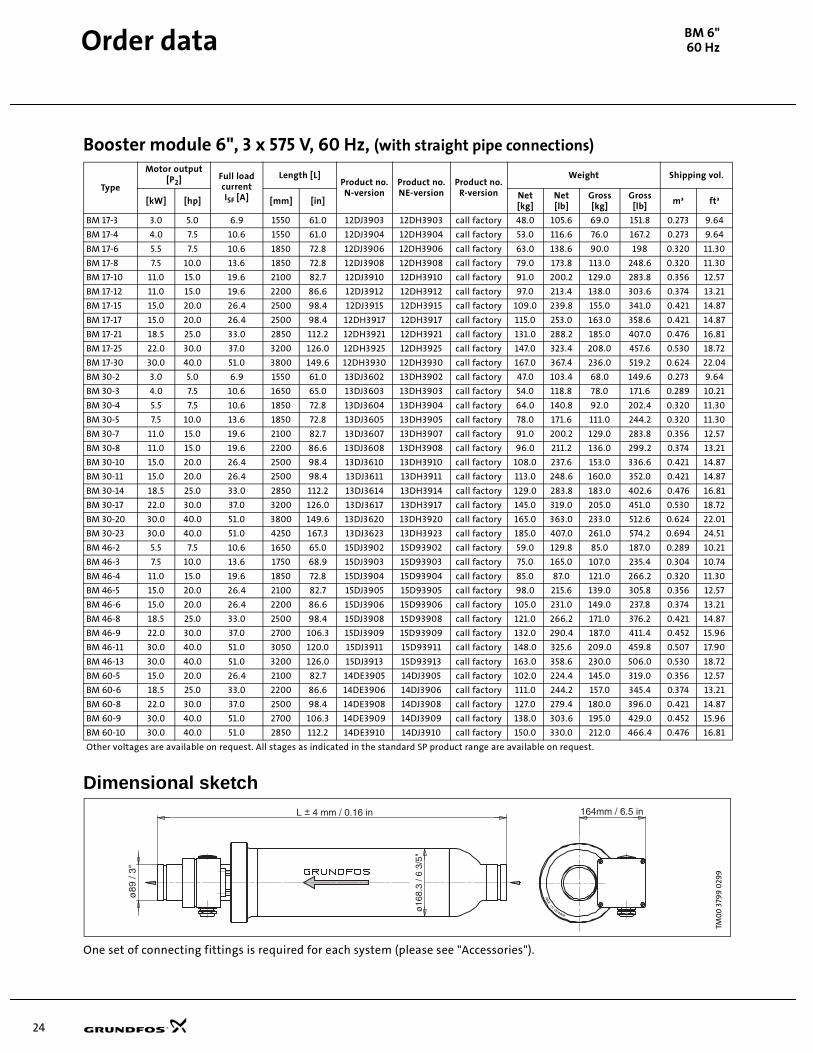
24
Booster module 6", 3 x 575 V, 60 Hz, (with straight pipe connections)
Dimensional sketch
One set of connecting fittings is required for each system (please see "Accessories").
Type
Motor output[P2] Full load
currentISF [A]
Length [L]Product no.N-version
Product no.NE-version
Product no.R-version
Weight Shipping vol.
[kW] [hp] [mm] [in]Net[kg]
Net[lb]
Gross [kg]
Gross [lb]
m³ ft³
BM 17-3 3.0 5.0 6.9 1550 61.0 12DJ3903 12DH3903 call factory 48.0 105.6 69.0 151.8 0.273 9.64
BM 17-4 4.0 7.5 10.6 1550 61.0 12DJ3904 12DH3904 call factory 53.0 116.6 76.0 167.2 0.273 9.64
BM 17-6 5.5 7.5 10.6 1850 72.8 12DJ3906 12DH3906 call factory 63.0 138.6 90.0 198 0.320 11.30
BM 17-8 7.5 10.0 13.6 1850 72.8 12DJ3908 12DH3908 call factory 79.0 173.8 113.0 248.6 0.320 11.30
BM 17-10 11.0 15.0 19.6 2100 82.7 12DJ3910 12DH3910 call factory 91.0 200.2 129.0 283.8 0.356 12.57
BM 17-12 11.0 15.0 19.6 2200 86.6 12DJ3912 12DH3912 call factory 97.0 213.4 138.0 303.6 0.374 13.21
BM 17-15 15.0 20.0 26.4 2500 98.4 12DJ3915 12DH3915 call factory 109.0 239.8 155.0 341.0 0.421 14.87
BM 17-17 15.0 20.0 26.4 2500 98.4 12DH3917 12DH3917 call factory 115.0 253.0 163.0 358.6 0.421 14.87
BM 17-21 18.5 25.0 33.0 2850 112.2 12DH3921 12DH3921 call factory 131.0 288.2 185.0 407.0 0.476 16.81
BM 17-25 22.0 30.0 37.0 3200 126.0 12DH3925 12DH3925 call factory 147.0 323.4 208.0 457.6 0.530 18.72
BM 17-30 30.0 40.0 51.0 3800 149.6 12DH3930 12DH3930 call factory 167.0 367.4 236.0 519.2 0.624 22.04
BM 30-2 3.0 5.0 6.9 1550 61.0 13DJ3602 13DH3902 call factory 47.0 103.4 68.0 149.6 0.273 9.64
BM 30-3 4.0 7.5 10.6 1650 65.0 13DJ3603 13DH3903 call factory 54.0 118.8 78.0 171.6 0.289 10.21
BM 30-4 5.5 7.5 10.6 1850 72.8 13DJ3604 13DH3904 call factory 64.0 140.8 92.0 202.4 0.320 11.30
BM 30-5 7.5 10.0 13.6 1850 72.8 13DJ3605 13DH3905 call factory 78.0 171.6 111.0 244.2 0.320 11.30
BM 30-7 11.0 15.0 19.6 2100 82.7 13DJ3607 13DH3907 call factory 91.0 200.2 129.0 283.8 0.356 12.57
BM 30-8 11.0 15.0 19.6 2200 86.6 13DJ3608 13DH3908 call factory 96.0 211.2 136.0 299.2 0.374 13.21
BM 30-10 15.0 20.0 26.4 2500 98.4 13DJ3610 13DH3910 call factory 108.0 237.6 153.0 336.6 0.421 14.87
BM 30-11 15.0 20.0 26.4 2500 98.4 13DJ3611 13DH3911 call factory 113.0 248.6 160.0 352.0 0.421 14.87
BM 30-14 18.5 25.0 33.0 2850 112.2 13DJ3614 13DH3914 call factory 129.0 283.8 183.0 402.6 0.476 16.81
BM 30-17 22.0 30.0 37.0 3200 126.0 13DJ3617 13DH3917 call factory 145.0 319.0 205.0 451.0 0.530 18.72
BM 30-20 30.0 40.0 51.0 3800 149.6 13DJ3620 13DH3920 call factory 165.0 363.0 233.0 512.6 0.624 22.01
BM 30-23 30.0 40.0 51.0 4250 167.3 13DJ3623 13DH3923 call factory 185.0 407.0 261.0 574.2 0.694 24.51
BM 46-2 5.5 7.5 10.6 1650 65.0 15DJ3902 15D93902 call factory 59.0 129.8 85.0 187.0 0.289 10.21
BM 46-3 7.5 10.0 13.6 1750 68.9 15DJ3903 15D93903 call factory 75.0 165.0 107.0 235.4 0.304 10.74
BM 46-4 11.0 15.0 19.6 1850 72.8 15DJ3904 15D93904 call factory 85.0 87.0 121.0 266.2 0.320 11.30
BM 46-5 15.0 20.0 26.4 2100 82.7 15DJ3905 15D93905 call factory 98.0 215.6 139.0 305.8 0.356 12.57
BM 46-6 15.0 20.0 26.4 2200 86.6 15DJ3906 15D93906 call factory 105.0 231.0 149.0 237.8 0.374 13.21
BM 46-8 18.5 25.0 33.0 2500 98.4 15DJ3908 15D93908 call factory 121.0 266.2 171.0 376.2 0.421 14.87
BM 46-9 22.0 30.0 37.0 2700 106.3 15DJ3909 15D93909 call factory 132.0 290.4 187.0 411.4 0.452 15.96
BM 46-11 30.0 40.0 51.0 3050 120.0 15DJ3911 15D93911 call factory 148.0 325.6 209.0 459.8 0.507 17.90
BM 46-13 30.0 40.0 51.0 3200 126.0 15DJ3913 15D93913 call factory 163.0 358.6 230.0 506.0 0.530 18.72
BM 60-5 15.0 20.0 26.4 2100 82.7 14DE3905 14DJ3905 call factory 102.0 224.4 145.0 319.0 0.356 12.57
BM 60-6 18.5 25.0 33.0 2200 86.6 14DE3906 14DJ3906 call factory 111.0 244.2 157.0 345.4 0.374 13.21
BM 60-8 22.0 30.0 37.0 2500 98.4 14DE3908 14DJ3908 call factory 127.0 279.4 180.0 396.0 0.421 14.87
BM 60-9 30.0 40.0 51.0 2700 106.3 14DE3909 14DJ3909 call factory 138.0 303.6 195.0 429.0 0.452 15.96
BM 60-10 30.0 40.0 51.0 2850 112.2 14DE3910 14DJ3910 call factory 150.0 330.0 212.0 466.4 0.476 16.81
Other voltages are available on request. All stages as indicated in the standard SP product range are available on request.
Booster module 6",(with straight pipe connections)
TM0
0 3
799
029
9
KRAMNED
NIED
AM
BM 6"60 HzOrder data
25
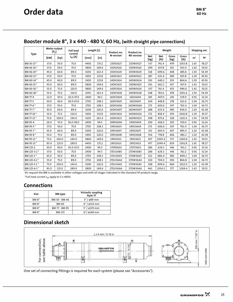
Booster module 8", 3 x 440 - 480 V, 60 Hz, (with straight pipe connections)
Connections
Dimensional sketch
One set of connecting fittings is required for each system (please see "Accessories").
Type
Motor output[P2] Full load
currentISF [A]
Length [L]Product no.N-version
Product no.NE-version
Weight Shipping vol.
[kW] [hp] [mm] [in]Net[kg]
Net[lb]
Gross [kg]
Gross [lb]
m³ ft³
BM 30-27 * 37.0 50.0 75.0 4450 175.2 13DK3627 13DW3627 337 741.4 479 1053.8 1.65 58.27
BM 46-16 * 37.0 50.0 75.0 3800 149.6 15DK3616 15DW3616 299 657.8 415 913.0 1.42 50.15
BM 46-19 * 45.0 60.0 89.0 4150 163.4 15DK3619 15DW3619 318 699.6 448 485.6 1.54 54.39
BM 60-13 * 37.0 50.0 75.0 3450 135.8 14DK3613 14DW3613 287 631.4 389 855.8 1.29 45.91
BM 60-14 * 45.0 60.0 89.0 3450 135.8 14DK3614 14DW3614 291 640.2 393 864.6 1.29 45.91
BM 60-15 * 45.0 60.0 89.0 3800 149.6 14DK3615 14DW3615 301 662.2 417 917.4 1.42 50.15
BM 60-16 * 55.0 75.0 110.0 3800 149.6 14DK3616 14DW3616 337 741.4 453 996.6 1.42 50.15
BM 60-18 * 55.0 75.0 110.0 4150 163.4 14DK3618 14DW3618 348 765.6 478 1051.6 1.54 54.39
BM 77-4 22.0 30.0 42.0-47.0 2400 94.5 16DE3604 16DJ3604 185 407.0 245 539.0 0.91 32.14
BM 77-5 30.0 40.0 65.0-67.0 2750 108.3 16DE3605 16DJ3605 204 448.8 278 611.6 1.04 36.73
BM 77-6 * 37.0 50.0 75.0 2750 108.3 16DK3606 16DW3606 273 600.6 347 763.4 1.04 36.73
BM 77-7 * 45.0 60.0 89.0 3200 126.0 16DK3607 16DW3607 288 633.6 380 836.0 1.20 42.38
BM 77-10 * 55.0 75.0 110.0 3450 135.8 16DK3610 16DW3610 372 818.4 474 1042.8 1.29 45.57
BM 77-13 * 75.0 100.0 144.0 4150 163.4 16DK3613 16DW3613 398 875.6 528 1161.6 1.54 54.39
BM 95-4 26.0 35.0 56.0-58.0 2400 94.5 19893604 19903604 190 418.0 250 550.0 0.91 32.14
BM 95-5 * 37.0 50.0 75.0 2750 108.3 19913605 19923604 273 600.6 347 763.4 1.04 36.73
BM 95-7 * 45.0 60.0 89.0 3200 126.0 19913607 19923607 315 693.0 407 895.4 1.20 42.38
BM 95-8 * 55.0 75.0 89.0 3450 126.0 19913608 19923608 354 778.8 446 981.2 1.20 42.38
BM 95-11 * 75.0 100.0 144.0 3800 149.6 19913611 19923611 457 1005.4 573 1260.6 1.42 50.15
BM 95-13 * 93.0 125.0 189.0 4450 175.2 19913613 19923613 477 1049.4 619 1361.8 1.65 58.27
BM 125-2 30.0 40.0 65.0-67.0 2400 94.5 17DR3602 17DT3602 286 629.2 346 761.2 0.91 32.14
BM 125-3-2 * 37.0 50.0 75.0 2400 94.5 17DU36B3 17DW36B3 286 629.2 346 761.2 0.91 32.14
BM 125-3 * 45.0 50.0 89.0 2750 108.3 17DU3603 17DW3603 312 686.4 386 849.2 1.04 36.73
BM 125-4-1 * 55.0 75.0 89.0 2750 108.3 17DU36A4 17DW36A4 320 704.0 394 866.8 1.04 36.73
BM 125-5-1 * 75.0 100.0 144.0 3200 126.0 17DU36A5 17DW36A5 368 809.6 460 1012.0 1.20 42.38
BM 125-6-1 * 93.0 125.0 189.0 3800 149.6 17DU36A6 17DW36A6 461 1014.2 577 1269.4 1.42 50.15
On request the BM is available in other voltages and with all stages indicated in the standard SP product range.
*Full load current ISF apply to 3 x 460V.
Size BM typeVictaulic coupling
Style 77
BM 8" BM 30 - BM 46 3" / ø89 mm
BM 8" BM 60 4" / ø114 mm
BM 8" BM 77 - BM 95 5" / ø139 mm
BM 8" BM 125 6"/ ø168 mm
TM0
1 14
24 0
99
8
For
con
nec
tio
n,
see
tab
le a
bo
ve
BM 8"60 HzOrder data
26
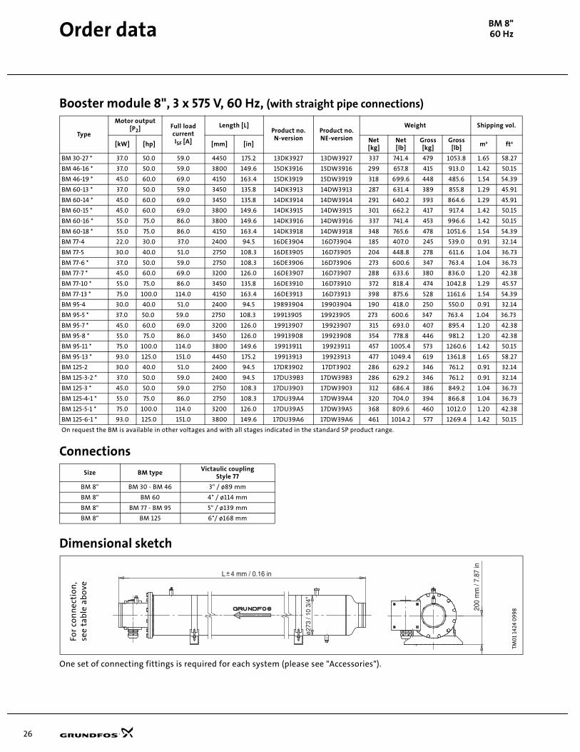
Booster module 8", 3 x 575 V, 60 Hz, (with straight pipe connections)
Connections
Dimensional sketch
One set of connecting fittings is required for each system (please see "Accessories").
Type
Motor output[P2] Full load
currentISF [A]
Length [L]Product no.N-version
Product no.NE-version
Weight Shipping vol.
[kW] [hp] [mm] [in]Net[kg]
Net[lb]
Gross [kg]
Gross [lb]
m³ ft³
BM 30-27 * 37.0 50.0 59.0 4450 175.2 13DK3927 13DW3927 337 741.4 479 1053.8 1.65 58.27
BM 46-16 * 37.0 50.0 59.0 3800 149.6 15DK3916 15DW3916 299 657.8 415 913.0 1.42 50.15
BM 46-19 * 45.0 60.0 69.0 4150 163.4 15DK3919 15DW3919 318 699.6 448 485.6 1.54 54.39
BM 60-13 * 37.0 50.0 59.0 3450 135.8 14DK3913 14DW3913 287 631.4 389 855.8 1.29 45.91
BM 60-14 * 45.0 60.0 69.0 3450 135.8 14DK3914 14DW3914 291 640.2 393 864.6 1.29 45.91
BM 60-15 * 45.0 60.0 69.0 3800 149.6 14DK3915 14DW3915 301 662.2 417 917.4 1.42 50.15
BM 60-16 * 55.0 75.0 86.0 3800 149.6 14DK3916 14DW3916 337 741.4 453 996.6 1.42 50.15
BM 60-18 * 55.0 75.0 86.0 4150 163.4 14DK3918 14DW3918 348 765.6 478 1051.6 1.54 54.39
BM 77-4 22.0 30.0 37.0 2400 94.5 16DE3904 16D73904 185 407.0 245 539.0 0.91 32.14
BM 77-5 30.0 40.0 51.0 2750 108.3 16DE3905 16D73905 204 448.8 278 611.6 1.04 36.73
BM 77-6 * 37.0 50.0 59.0 2750 108.3 16DE3906 16D73906 273 600.6 347 763.4 1.04 36.73
BM 77-7 * 45.0 60.0 69.0 3200 126.0 16DE3907 16D73907 288 633.6 380 836.0 1.20 42.38
BM 77-10 * 55.0 75.0 86.0 3450 135.8 16DE3910 16D73910 372 818.4 474 1042.8 1.29 45.57
BM 77-13 * 75.0 100.0 114.0 4150 163.4 16DE3913 16D73913 398 875.6 528 1161.6 1.54 54.39
BM 95-4 30.0 40.0 51.0 2400 94.5 19893904 19903904 190 418.0 250 550.0 0.91 32.14
BM 95-5 * 37.0 50.0 59.0 2750 108.3 19913905 19923905 273 600.6 347 763.4 1.04 36.73
BM 95-7 * 45.0 60.0 69.0 3200 126.0 19913907 19923907 315 693.0 407 895.4 1.20 42.38
BM 95-8 * 55.0 75.0 86.0 3450 126.0 19913908 19923908 354 778.8 446 981.2 1.20 42.38
BM 95-11 * 75.0 100.0 114.0 3800 149.6 19913911 19923911 457 1005.4 573 1260.6 1.42 50.15
BM 95-13 * 93.0 125.0 151.0 4450 175.2 19913913 19923913 477 1049.4 619 1361.8 1.65 58.27
BM 125-2 30.0 40.0 51.0 2400 94.5 17DR3902 17DT3902 286 629.2 346 761.2 0.91 32.14
BM 125-3-2 * 37.0 50.0 59.0 2400 94.5 17DU39B3 17DW39B3 286 629.2 346 761.2 0.91 32.14
BM 125-3 * 45.0 50.0 59.0 2750 108.3 17DU3903 17DW3903 312 686.4 386 849.2 1.04 36.73
BM 125-4-1 * 55.0 75.0 86.0 2750 108.3 17DU39A4 17DW39A4 320 704.0 394 866.8 1.04 36.73
BM 125-5-1 * 75.0 100.0 114.0 3200 126.0 17DU39A5 17DW39A5 368 809.6 460 1012.0 1.20 42.38
BM 125-6-1 * 93.0 125.0 151.0 3800 149.6 17DU39A6 17DW39A6 461 1014.2 577 1269.4 1.42 50.15
On request the BM is available in other voltages and with all stages indicated in the standard SP product range.
Size BM typeVictaulic coupling
Style 77
BM 8" BM 30 - BM 46 3" / ø89 mm
BM 8" BM 60 4" / ø114 mm
BM 8" BM 77 - BM 95 5" / ø139 mm
BM 8" BM 125 6"/ ø168 mmTM
01
1424
09
98
For
con
nec
tio
n,
see
tab
le a
bo
ve
BM 8"60 HzOrder data
27
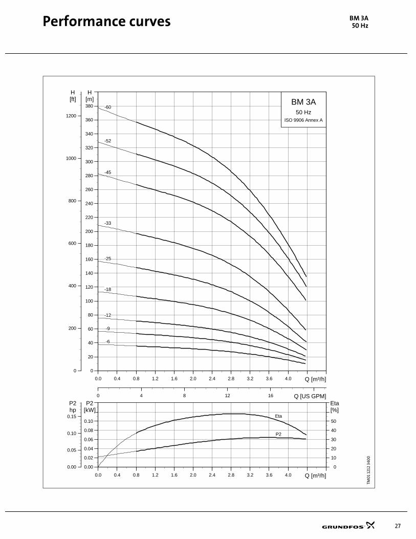
Performance curves BM 3A50 Hz
TM0
1 12
12 3
400Pe
rfo
rman
ce c
urv
es, 5
0 H
zBM
3A
0.0 0.4 0.8 1.2 1.6 2.0 2.4 2.8 3.2 3.6 4.0 Q [m³/h]
0.00
0.02
0.04
0.06
0.08
0.10
P2[kW]
0
10
20
30
40
50
Eta[%]
0.00
0.05
0.10
0.15hpP2
Eta
P2
0.0 0.4 0.8 1.2 1.6 2.0 2.4 2.8 3.2 3.6 4.0 Q [m³/h]
0
20
40
60
80
100
120
140
160
180
200
220
240
260
280
300
320
340
360
380
H[m]
0
200
400
600
800
1000
1200
H[ft]
0 4 8 12 16 Q [US GPM]
BM 3A
ISO 9906 Annex A
50 Hz
-12
-18
-25
-33
-45
-52
-6
-60
-9

28
Performance curves BM 5A50 Hz
TM0
1 12
13 3
400
0.0 0.8 1.6 2.4 3.2 4.0 4.8 5.6 6.4 Q [m³/h]
0.00
0.02
0.04
0.06
0.08
0.10
P2[kW]
0
10
20
30
40
50
Eta[%]
0.00
0.05
0.10
0.15hpP2
Eta
P2
0.0 0.8 1.6 2.4 3.2 4.0 4.8 5.6 6.4 Q [m³/h]
0
20
40
60
80
100
120
140
160
180
200
220
240
260
280
300
320
340
360
380
H[m]
0
200
400
600
800
1000
1200
H[ft]
0 5 10 15 20 25 Q [US GPM]
BM 5A
ISO 9906 Annex A
50 Hz
-25
-33
-38
-44
-60
-17
-12
29
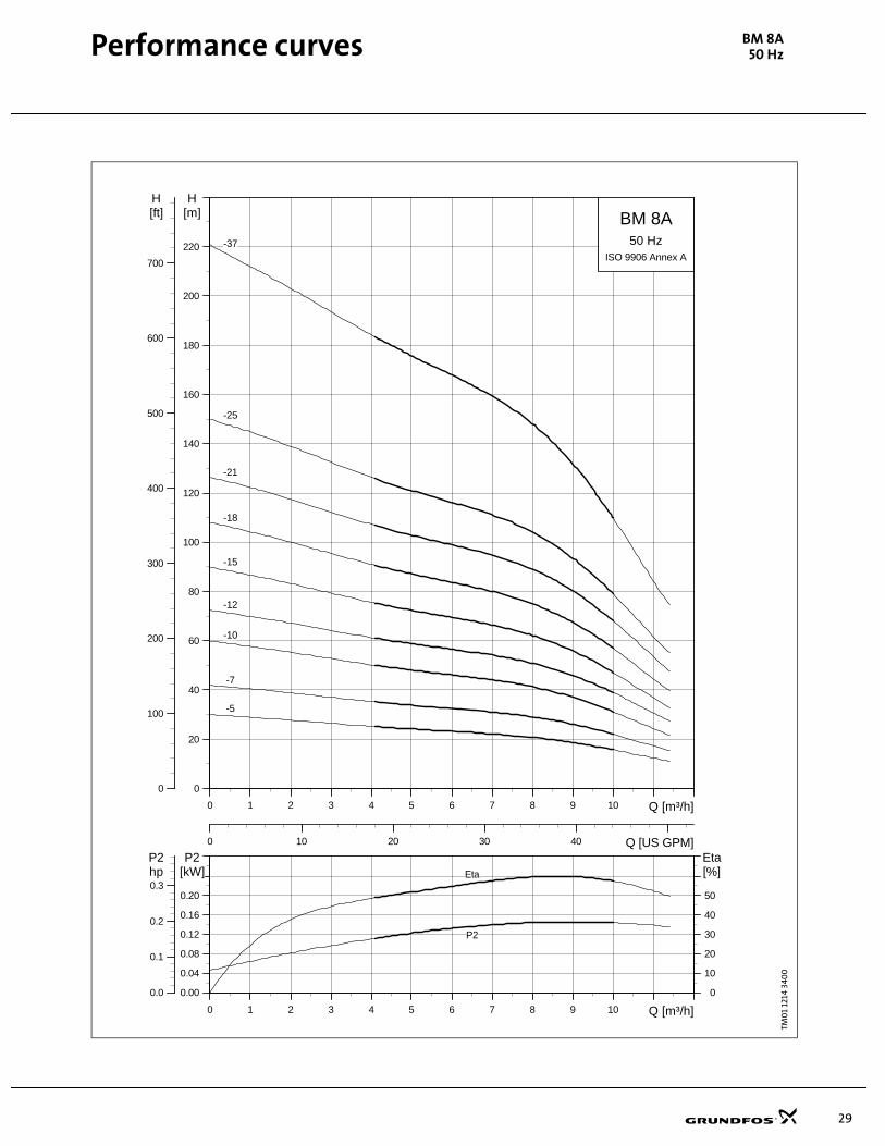
Performance curves BM 8A50 Hz
TM0
1 12
14 3
400
0 1 2 3 4 5 6 7 8 9 10 Q [m³/h]
0.00
0.04
0.08
0.12
0.16
0.20
P2[kW]
0
10
20
30
40
50
Eta[%]
0.0
0.1
0.2
0.3hpP2
Eta
P2
0 1 2 3 4 5 6 7 8 9 10 Q [m³/h]
0
20
40
60
80
100
120
140
160
180
200
220
H[m]
0
100
200
300
400
500
600
700
H[ft]
0 10 20 30 40 Q [US GPM]
BM 8A
ISO 9906 Annex A
50 Hz
-10
-12
-15
-18
-21
-25
-37
-5
-7

30
Performance curves BM 1750 Hz
TM0
0 3
69
9 3
400
0 2 4 6 8 10 12 14 16 18 20 Q [m³/h]
0.0
0.2
0.4
0.6
0.8
P2[kW]
0
20
40
60
80
Eta[%]
0.0
0.3
0.6
0.9
hpP2
EtaP2
0 2 4 6 8 10 12 14 16 18 20 Q [m³/h]
0
40
80
120
160
200
240
280
320
360
400
440
480
H[m]
0
200
400
600
800
1000
1200
1400
1600
H[ft]
0 20 40 60 80 Q [US GPM]
BM 17
ISO 9906 Annex A
50 Hz
-13
-16
-19
-22
-26
-32
-38
-40
-5
-9
31
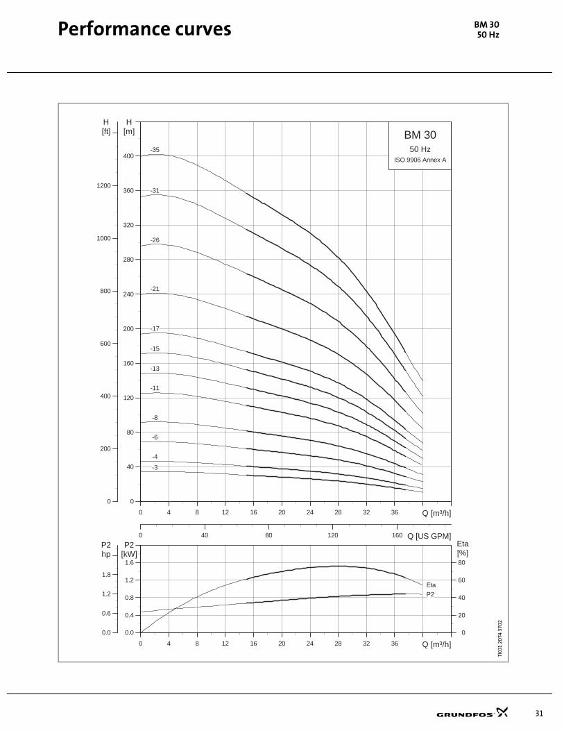
Performance curves BM 3050 Hz
TK0
1 20
74 3
702
0 4 8 12 16 20 24 28 32 36 Q [m³/h]
0.0
0.4
0.8
1.2
1.6
P2[kW]
0
20
40
60
80
Eta[%]
0.0
0.6
1.2
1.8
hpP2
P2
Eta
0 4 8 12 16 20 24 28 32 36 Q [m³/h]
0
40
80
120
160
200
240
280
320
360
400
H[m]
0
200
400
600
800
1000
1200
H[ft]
0 40 80 120 160 Q [US GPM]
BM 30
ISO 9906 Annex A
50 Hz
-11
-13
-15
-17
-21
-26
-3
-31
-35
-4
-6
-8
32
Performance curves BM 4650 Hz
TM0
1 12
17 3
400
0 8 16 24 32 40 48 56 64 Q [m³/h]
0.0
0.4
0.8
1.2
1.6
P2[kW]
0
20
40
60
80
Eta[%]
0.0
0.6
1.2
1.8
hpP2
EtaP2
0 8 16 24 32 40 48 56 64 Q [m³/h]
0
40
80
120
160
200
240
280
320
360
H[m]
0
200
400
600
800
1000
1200
H[ft]
0 50 100 150 200 250 Q [US GPM]
BM 46
ISO 9906 Annex A
50 Hz
-10
-12
-15
-17
-19
-2
-20
-24
-3
-5
-6
-7
-8

33
Performance curves BM 6050 Hz
TM0
1 12
18 3
400
0 8 16 24 32 40 48 56 64 72 Q [m³/h]
0.0
0.8
1.6
2.4
3.2
P2[kW]
0
20
40
60
80
Eta[%]
0
1
2
3
4
hpP2
Eta
P2
0 8 16 24 32 40 48 56 64 72 Q [m³/h]
0
20
40
60
80
100
120
140
160
180
200
220
240
260
280
300
320
H[m]
0
200
400
600
800
1000
H[ft]
0 50 100 150 200 250 300 Q [US GPM]
BM 60
ISO 9906 Annex A
50 Hz
-10
-12
-15
-16
-20
-22
-5
-6
-7
-8
34
Performance curves BM 7750 Hz
TM0
1 12
19 3
400
0 10 20 30 40 50 60 70 80 90 Q [m³/h]
0
1
2
3
4
P2[kW]
0
20
40
60
80
Eta[%]
0
2
4
hpP2
Eta
P2
0 10 20 30 40 50 60 70 80 90 Q [m³/h]
0
40
80
120
160
200
240
280
320
360
400
440
H[m]
0
200
400
600
800
1000
1200
1400
H[ft]
0 100 200 300 400 Q [US GPM]
BM 77
ISO 9906 Annex A
50 Hz
-10
-12
-14
-20
-6
-7
-8
35
Performance curves BM 9550 Hz
TM0
1 20
75 3
400
0 10 20 30 40 50 60 70 80 90 100 110 Q [m³/h]
0
2
4
6
8
P2[kW]
0
20
40
60
80
Eta[%]
0
3
6
9
hpP2
Eta
P2
0 10 20 30 40 50 60 70 80 90 100 110 Q [m³/h]
0
40
80
120
160
200
240
280
320
360
400
440
H[m]
0
200
400
600
800
1000
1200
1400
H[ft]
0 100 200 300 400 Q [US GPM]
BM 95
ISO 9906 Annex A
50 Hz
-10
-12
-16
-20
-6
-8
36
Performance curves BM 12550 Hz
TM0
1 20
76 3
40
0
0 20 40 60 80 100 120 140 160Q [m³/h]
0
3
6
9
12
P2[kW]
0
20
40
60
80
Eta[%]
0
5
10
15
hpP2
EtaP2
0 20 40 60 80 100 120 140 160Q [m³/h]
0
20
40
60
80
100
120
140
160
180
200
220
240
260
280
H[m]
0
200
400
600
800
H[ft]
0 200 400 600 Q [US GPM]
BM 125
ISO 9906 Annex A
50 Hz
-3
-4-1
-5
-7
-9
-4

37
Order data BM 4"50 Hz
Booster module 4", 3 x 380 - 415 V, 50 Hz, (with straight pipe connections)
Dimensional sketch
One set of connecting fittings is required for each system (see "Accessories").
Type
Motor output[P2] Nominal
currentIN [A]
Length [L]Product no.N-version
Product no.NE-version
Product no.R-version
Weight Shipping vol.
[kW] [hp] [mm] [in]Net[kg]
Net[lb]
Gross [kg]
Gross [lb]
m³ ft³
BM 3A- 6 0.75 1.0 1.92-1.84 1222 45.0 10731906 10741906 - 31.0 68.2 37.0 81.4 0.095 3.35
BM 3A- 9 0.75 1.0 1.92-1.84 1222 45.0 10731909 10741909 - 32.0 70.4 38.0 83.6 0.095 3.35
BM 3A-12 0.75 1.0 1.92-1.84 1222 45.0 10731912 10741912 - 33.0 72.6 39.0 85.8 0.095 3.35
BM 3A-18 1.1 1.5 2.80-2.75 1369 50.8 10731918 10741918 - 37.0 81.4 43.0 94.6 0.100 3.53
BM 3A-25 1.5 2.0 3.95-4.10 1640 61.5 10731925 10741925 - 41.0 90.2 47.0 103.4 0.120 4.24
BM 3A-33 2.2 3.0 5.85-6.45 1758 66.1 10731933 10741933 - 46.0 101.2 52.0 114.4 0.126 4.44
BM 3A-45 3.0 4.0 8.35-8.10 1986 75.1 10731945 10741945 - 53.0 116.6 59.0 129.8 0.142 5.01
BM 3A-52 4.0 5.5 9.75-9.80 2346 89.3 10731952 10741952 - 62.0 136.4 69.0 151.8 0.170 6.00
BM 3A-60 4.0 5.5 9.75-9.80 2490 95.0 10731960 10741960 - 65.0 143 72.0 158.4 0.175 6.18
BM 5A-12 1.1 1.5 2.80-2.75 1222 45.0 05731912 05741912 05771912 34.0 74.8 40.0 88.0 0.095 3.35
BM 5A-17 1.5 2.0 3.95-4.10 1369 50.8 05731917 05741917 05771917 36.0 79.2 42.0 92.4 0.100 3.53
BM 5A-25 2.2 3.0 5.85-6.45 1640 61.5 05731925 05741925 05771925 43.0 94.6 49.0 107.8 0.120 4.24
BM 5A-33 3.0 4.0 8.35-8.10 1986 75.1 05731933 05741933 05771933 49.0 107.8 55.0 121.0 0.142 5.01
BM 5A-38 4.0 5.5 9.75-9.80 1986 75.1 05731938 05741938 05771938 54.0 118.8 60.0 132.0 0.142 5.01
BM 5A-44 4.0 5.5 9.75-9.80 2112 80.1 05731944 05741944 05771944 57.0 125.4 64.0 140.8 0.149 5.26
BM 5A-60 5.5 7.5 13.0-13.4 2490 98.0 05731960 05741960 05771960 70.0 154 77.0 169.4 0.175 6.18
BM 8A- 5 0.75 1.0 1.92-1.84 1222 45.0 11731905 11741905 11771905 32.0 70.4 38.0 83.6 0.095 3.35
BM 8A- 7 1.1 1.5 2.80-2.75 1369 50.8 11731907 11741907 11771907 35.0 77.0 41.0 90.2 0.100 3.53
BM 8A-10 1.5 2.0 3.95-4.10 1472 54.9 11731910 11741910 11771910 37.0 81.4 43.0 94.6 0.106 3.74
BM 8A-12 2.2 3.0 5.85-6.45 1640 61.5 11731912 11741912 11771912 41.0 90.2 47.0 103.4 0.120 4.24
BM 8A-15 2.2 3.0 5.85-6.45 1758 66.1 11731915 11741915 11771915 44.0 96.8 50.0 110.0 0.126 4.44
BM 8A-18 3.0 4.0 8.35-8.10 1986 75.1 11731918 11741918 11771918 48.0 105.6 54.0 118.8 0.142 5.01
BM 8A-21 4.0 5.5 9.75-9.80 2112 80.1 11731921 11741921 11771921 54.0 118.8 61.0 134.2 0.149 5.26
BM 8A-25 4.0 5.5 9.75-9.80 2346 89.3 11731925 11741925 11771925 57.0 125.4 64.0 140.8 0.170 6.00
BM 8A-37 5.5 7.5 13.0-13.4 2737 107.8 11731937 11741937 11771937 73.0 160.6 81.0 178.2 0.192 6.78
Other voltages are available on request. All stages as indicated in the standard SP product range are available on request.
Order data, 50 Hz
TM0
0 3
797
029
9
ø11
4.3
/ 4.5
"
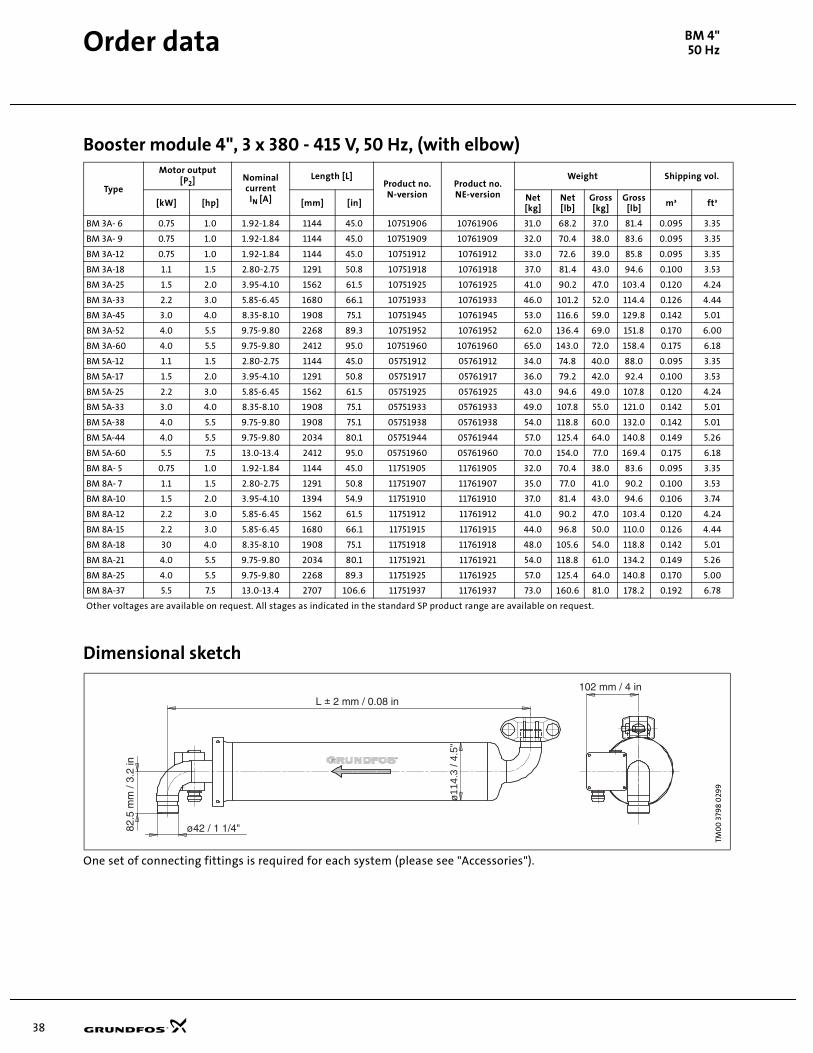
38
Order data BM 4"50 Hz
Booster module 4", 3 x 380 - 415 V, 50 Hz, (with elbow)
Dimensional sketch
One set of connecting fittings is required for each system (please see "Accessories").
Type
Motor output[P2] Nominal
currentIN [A]
Length [L]Product no.N-version
Product no.NE-version
Weight Shipping vol.
[kW] [hp] [mm] [in]Net[kg]
Net[lb]
Gross [kg]
Gross [lb]
m³ ft³
BM 3A- 6 0.75 1.0 1.92-1.84 1144 45.0 10751906 10761906 31.0 68.2 37.0 81.4 0.095 3.35
BM 3A- 9 0.75 1.0 1.92-1.84 1144 45.0 10751909 10761909 32.0 70.4 38.0 83.6 0.095 3.35
BM 3A-12 0.75 1.0 1.92-1.84 1144 45.0 10751912 10761912 33.0 72.6 39.0 85.8 0.095 3.35
BM 3A-18 1.1 1.5 2.80-2.75 1291 50.8 10751918 10761918 37.0 81.4 43.0 94.6 0.100 3.53
BM 3A-25 1.5 2.0 3.95-4.10 1562 61.5 10751925 10761925 41.0 90.2 47.0 103.4 0.120 4.24
BM 3A-33 2.2 3.0 5.85-6.45 1680 66.1 10751933 10761933 46.0 101.2 52.0 114.4 0.126 4.44
BM 3A-45 3.0 4.0 8.35-8.10 1908 75.1 10751945 10761945 53.0 116.6 59.0 129.8 0.142 5.01
BM 3A-52 4.0 5.5 9.75-9.80 2268 89.3 10751952 10761952 62.0 136.4 69.0 151.8 0.170 6.00
BM 3A-60 4.0 5.5 9.75-9.80 2412 95.0 10751960 10761960 65.0 143.0 72.0 158.4 0.175 6.18
BM 5A-12 1.1 1.5 2.80-2.75 1144 45.0 05751912 05761912 34.0 74.8 40.0 88.0 0.095 3.35
BM 5A-17 1.5 2.0 3.95-4.10 1291 50.8 05751917 05761917 36.0 79.2 42.0 92.4 0.100 3.53
BM 5A-25 2.2 3.0 5.85-6.45 1562 61.5 05751925 05761925 43.0 94.6 49.0 107.8 0.120 4.24
BM 5A-33 3.0 4.0 8.35-8.10 1908 75.1 05751933 05761933 49.0 107.8 55.0 121.0 0.142 5.01
BM 5A-38 4.0 5.5 9.75-9.80 1908 75.1 05751938 05761938 54.0 118.8 60.0 132.0 0.142 5.01
BM 5A-44 4.0 5.5 9.75-9.80 2034 80.1 05751944 05761944 57.0 125.4 64.0 140.8 0.149 5.26
BM 5A-60 5.5 7.5 13.0-13.4 2412 95.0 05751960 05761960 70.0 154.0 77.0 169.4 0.175 6.18
BM 8A- 5 0.75 1.0 1.92-1.84 1144 45.0 11751905 11761905 32.0 70.4 38.0 83.6 0.095 3.35
BM 8A- 7 1.1 1.5 2.80-2.75 1291 50.8 11751907 11761907 35.0 77.0 41.0 90.2 0.100 3.53
BM 8A-10 1.5 2.0 3.95-4.10 1394 54.9 11751910 11761910 37.0 81.4 43.0 94.6 0.106 3.74
BM 8A-12 2.2 3.0 5.85-6.45 1562 61.5 11751912 11761912 41.0 90.2 47.0 103.4 0.120 4.24
BM 8A-15 2.2 3.0 5.85-6.45 1680 66.1 11751915 11761915 44.0 96.8 50.0 110.0 0.126 4.44
BM 8A-18 30 4.0 8.35-8.10 1908 75.1 11751918 11761918 48.0 105.6 54.0 118.8 0.142 5.01
BM 8A-21 4.0 5.5 9.75-9.80 2034 80.1 11751921 11761921 54.0 118.8 61.0 134.2 0.149 5.26
BM 8A-25 4.0 5.5 9.75-9.80 2268 89.3 11751925 11761925 57.0 125.4 64.0 140.8 0.170 5.00
BM 8A-37 5.5 7.5 13.0-13.4 2707 106.6 11751937 11761937 73.0 160.6 81.0 178.2 0.192 6.78
Other voltages are available on request. All stages as indicated in the standard SP product range are available on request.
TM0
0 3
798
029
9
ø11
4.3
/ 4.5
"
39
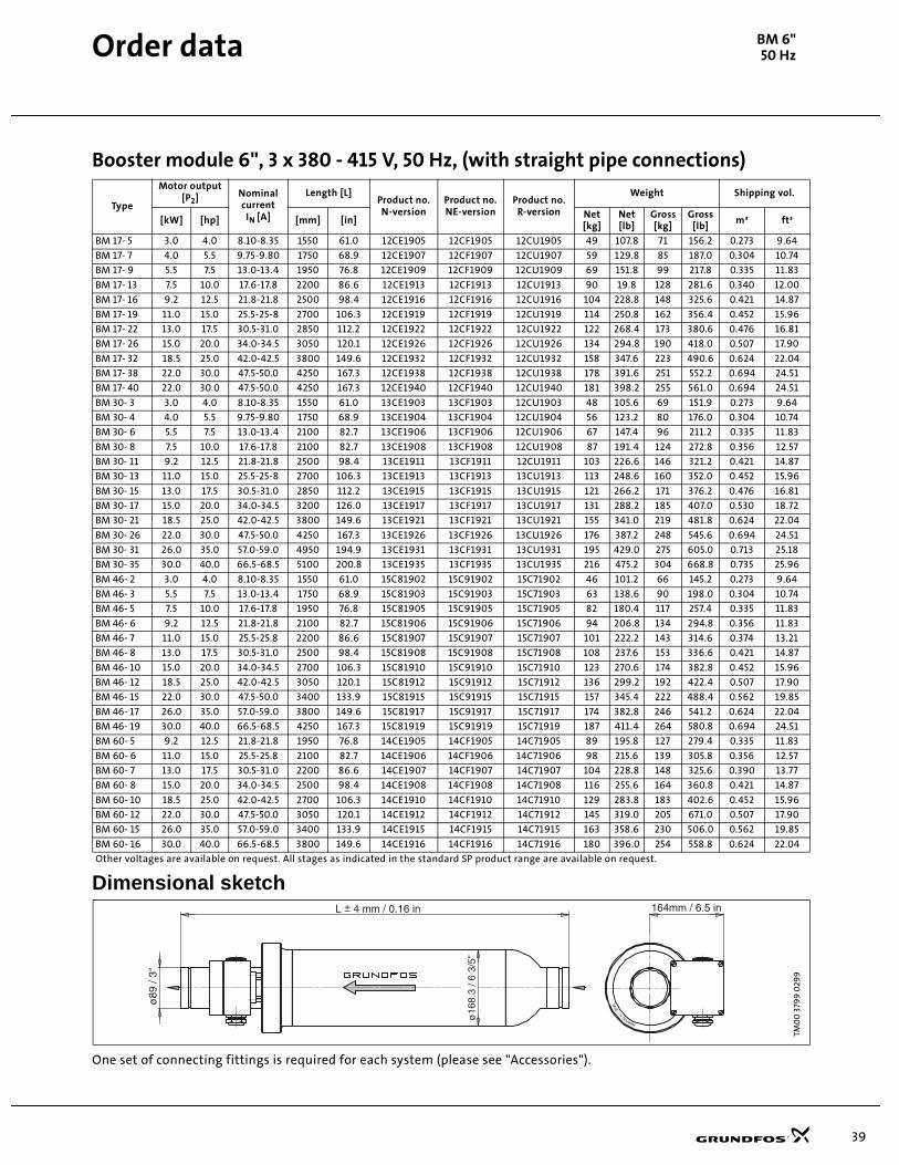
Order data BM 6"50 Hz
Booster module 6", 3 x 380 - 415 V, 50 Hz, (with straight pipe connections)
Dimensional sketch
One set of connecting fittings is required for each system (please see "Accessories").
Type
Motor output[P2] Nominal
currentIN [A]
Length [L]Product no.N-version
Product no.NE-version
Product no.R-version
Weight Shipping vol.
[kW] [hp] [mm] [in]Net[kg]
Net[lb]
Gross [kg]
Gross [lb]
m³ ft³
BM 17- 5 3.0 4.0 8.10-8.35 1550 61.0 12CE1905 12CF1905 12CU1905 49 107.8 71 156.2 0.273 9.64
BM 17- 7 4.0 5.5 9.75-9.80 1750 68.9 12CE1907 12CF1907 12CU1907 59 129.8 85 187.0 0.304 10.74
BM 17- 9 5.5 7.5 13.0-13.4 1950 76.8 12CE1909 12CF1909 12CU1909 69 151.8 99 217.8 0.335 11.83
BM 17- 13 7.5 10.0 17.6-17.8 2200 86.6 12CE1913 12CF1913 12CU1913 90 19.8 128 281.6 0.340 12.00
BM 17- 16 9.2 12.5 21.8-21.8 2500 98.4 12CE1916 12CF1916 12CU1916 104 228.8 148 325.6 0.421 14.87
BM 17- 19 11.0 15.0 25.5-25-8 2700 106.3 12CE1919 12CF1919 12CU1919 114 250.8 162 356.4 0.452 15.96
BM 17- 22 13.0 17.5 30.5-31.0 2850 112.2 12CE1922 12CF1922 12CU1922 122 268.4 173 380.6 0.476 16.81
BM 17- 26 15.0 20.0 34.0-34.5 3050 120.1 12CE1926 12CF1926 12CU1926 134 294.8 190 418.0 0.507 17.90
BM 17- 32 18.5 25.0 42.0-42.5 3800 149.6 12CE1932 12CF1932 12CU1932 158 347.6 223 490.6 0.624 22.04
BM 17- 38 22.0 30.0 47.5-50.0 4250 167.3 12CE1938 12CF1938 12CU1938 178 391.6 251 552.2 0.694 24.51
BM 17- 40 22.0 30.0 47.5-50.0 4250 167.3 12CE1940 12CF1940 12CU1940 181 398.2 255 561.0 0.694 24.51
BM 30- 3 3.0 4.0 8.10-8.35 1550 61.0 13CE1903 13CF1903 12CU1903 48 105.6 69 151.9 0.273 9.64
BM 30- 4 4.0 5.5 9.75-9.80 1750 68.9 13CE1904 13CF1904 12CU1904 56 123.2 80 176.0 0.304 10.74
BM 30- 6 5.5 7.5 13.0-13.4 2100 82.7 13CE1906 13CF1906 12CU1906 67 147.4 96 211.2 0.335 11.83
BM 30- 8 7.5 10.0 17.6-17.8 2100 82.7 13CE1908 13CF1908 12CU1908 87 191.4 124 272.8 0.356 12.57
BM 30- 11 9.2 12.5 21.8-21.8 2500 98.4 13CE1911 13CF1911 12CU1911 103 226.6 146 321.2 0.421 14.87
BM 30- 13 11.0 15.0 25.5-25-8 2700 106.3 13CE1913 13CF1913 13CU1913 113 248.6 160 352.0 0.452 15.96
BM 30- 15 13.0 17.5 30.5-31.0 2850 112.2 13CE1915 13CF1915 13CU1915 121 266.2 171 376.2 0.476 16.81
BM 30- 17 15.0 20.0 34.0-34.5 3200 126.0 13CE1917 13CF1917 13CU1917 131 288.2 185 407.0 0.530 18.72
BM 30- 21 18.5 25.0 42.0-42.5 3800 149.6 13CE1921 13CF1921 13CU1921 155 341.0 219 481.8 0.624 22.04
BM 30- 26 22.0 30.0 47.5-50.0 4250 167.3 13CE1926 13CF1926 13CU1926 176 387.2 248 545.6 0.694 24.51
BM 30- 31 26.0 35.0 57.0-59.0 4950 194.9 13CE1931 13CF1931 13CU1931 195 429.0 275 605.0 0.713 25.18
BM 30- 35 30.0 40.0 66.5-68.5 5100 200.8 13CE1935 13CF1935 13CU1935 216 475.2 304 668.8 0.735 25.96
BM 46- 2 3.0 4.0 8.10-8.35 1550 61.0 15C81902 15C91902 15C71902 46 101.2 66 145.2 0.273 9.64
BM 46- 3 5.5 7.5 13.0-13.4 1750 68.9 15C81903 15C91903 15C71903 63 138.6 90 198.0 0.304 10.74
BM 46- 5 7.5 10.0 17.6-17.8 1950 76.8 15C81905 15C91905 15C71905 82 180.4 117 257.4 0.335 11.83
BM 46- 6 9.2 12.5 21.8-21.8 2100 82.7 15C81906 15C91906 15C71906 94 206.8 134 294.8 0.356 11.83
BM 46- 7 11.0 15.0 25.5-25.8 2200 86.6 15C81907 15C91907 15C71907 101 222.2 143 314.6 0.374 13.21
BM 46- 8 13.0 17.5 30.5-31.0 2500 98.4 15C81908 15C91908 15C71908 108 237.6 153 336.6 0.421 14.87
BM 46- 10 15.0 20.0 34.0-34.5 2700 106.3 15C81910 15C91910 15C71910 123 270.6 174 382.8 0.452 15.96
BM 46- 12 18.5 25.0 42.0-42.5 3050 120.1 15C81912 15C91912 15C71912 136 299.2 192 422.4 0.507 17.90
BM 46- 15 22.0 30.0 47.5-50.0 3400 133.9 15C81915 15C91915 15C71915 157 345.4 222 488.4 0.562 19.85
BM 46- 17 26.0 35.0 57.0-59.0 3800 149.6 15C81917 15C91917 15C71917 174 382.8 246 541.2 0.624 22.04
BM 46- 19 30.0 40.0 66.5-68.5 4250 167.3 15C81919 15C91919 15C71919 187 411.4 264 580.8 0.694 24.51
BM 60- 5 9.2 12.5 21.8-21.8 1950 76.8 14CE1905 14CF1905 14C71905 89 195.8 127 279.4 0.335 11.83
BM 60- 6 11.0 15.0 25.5-25.8 2100 82.7 14CE1906 14CF1906 14C71906 98 215.6 139 305.8 0.356 12.57
BM 60- 7 13.0 17.5 30.5-31.0 2200 86.6 14CE1907 14CF1907 14C71907 104 228.8 148 325.6 0.390 13.77
BM 60- 8 15.0 20.0 34.0-34.5 2500 98.4 14CE1908 14CF1908 14C71908 116 255.6 164 360.8 0.421 14.87
BM 60- 10 18.5 25.0 42.0-42.5 2700 106.3 14CE1910 14CF1910 14C71910 129 283.8 183 402.6 0.452 15.96
BM 60- 12 22.0 30.0 47.5-50.0 3050 120.1 14CE1912 14CF1912 14C71912 145 319.0 205 671.0 0.507 17.90
BM 60- 15 26.0 35.0 57.0-59.0 3400 133.9 14CE1915 14CF1915 14C71915 163 358.6 230 506.0 0.562 19.85
BM 60- 16 30.0 40.0 66.5-68.5 3800 149.6 14CE1916 14CF1916 14C71916 180 396.0 254 558.8 0.624 22.04
Other voltages are available on request. All stages as indicated in the standard SP product range are available on request.
TM0
0 3
799
029
9
KRAMNED
NIED
AM
40
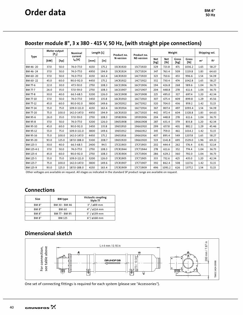
Order data BM 6"50 Hz
Booster module 8", 3 x 380 - 415 V, 50 Hz, (with straight pipe connections)
Connections
Dimensional sketch
One set of connecting fittings is required for each system (please see "Accessories").
Type
Motor output[P2] Nominal
currentIN [A]
Length [L]Product no.N-version
Product no.NE-version
Weight Shipping vol.
[kW] [hp] [mm] [in]Net[kg]
Net[lb]
Gross [kg]
Gross [lb]
m³ ft³
BM 46- 20 37.0 50.0 74.0-77.0 4150 175.2 15CR1920 15CT1920 329 723.8 471 1036.2 1.65 58.27
BM 46- 24 37.0 50.0 74.0-77.0 4950 194.9 15CR1924 15CT1924 347 763.4 509 1119.8 1.83 64.63
BM 60- 20 37.0 50.0 74.0-77.0 4150 163.4 14CR1920 14CT1920 323 710.6 453 996.6 1.54 54.39
BM 60- 22 45.0 60.0 90.0-92.0 4450 175.2 14CR1922 14CT1922 332 730.4 474 1042.8 1.65 58.27
BM 77-6 22.0 30.0 47.5-50.0 2750 108.3 16CE1906 16CF1906 194 426.8 268 589.6 1.04 36.73
BM 77-7 26.0 35.0 57.0-59.0 2750 108.3 16CE1907 16CF1907 204 448.8 278 611.6 1.04 36.73
BM 77-8 30.0 40.0 66.5-68.5 3200 126.0 16CE1908 16CF1908 225 495.0 317 697.4 1.20 42.34
BM 77-10 37.0 50.0 74.0-77.0 3450 135.8 16CR1910 16CT1910 307 675.4 409 899.8 1.29 45.56
BM 77-12 45.0 60.0 90.0-92.0 3800 149.6 16CR1912 16CT1912 320 704.0 436 959.2 1.42 51.15
BM 77-14 55.0 75.0 109.0-111.0 4150 163.4 16CR1914 16CT1914 367 807.4 497 1093.4 1.54 54.39
BM 77-20 75.0 100.0 142.0-147.0 4950 194.9 16CR1920 16CT1920 442 972.4 604 1328.8 1.83 64.63
BM 95-6 26.0 35.0 57.0-59.0 2750 108.3 19581906 19591906 204 448.8 278 611.6 1.04 36.73
BM 95-8 37.0 50.0 74.0-77.0 3200 126.0 19651908 19661908 287 631.4 379 833.8 1.20 42.34
BM 95-10 45.0 60.0 90.0-92.0 3450 135.8 19651910 19661910 299 657.8 401 882.2 1.29 45.46
BM 95-12 55.0 75.0 109.0-111.0 3800 149.6 19651912 19661912 345 759.0 461 1014.2 1.42 51.15
BM 95-16 75.0 100.0 142.0-147.0 4450 175.2 19651916 19661916 407 895.4 549 1207.8 1.65 58.27
BM 95-20 93.0 125.0 187.0-188.0 5300 208.7 19651920 19661920 519 1141.8 695 1529.0 1.96 69.22
BM 125-3 30.0 40.0 66.5-68.5 2400 94.5 17CE1903 17CF1903 202 444.4 262 576.4 0.91 32.14
BM 125-4-1 37.0 50.0 74.0-77.0 2750 108.3 17CR19A4 17CT19A4 278 611.6 352 774.4 1.04 36.73
BM 125-4 45.0 60.0 90.0-92.0 2750 108.3 17CR1904 17CT1904 286 629.2 360 792.0 1.04 36.73
BM 125-5 55.0 75.0 109.0-111.0 3200 126.0 17CR1905 17CT1905 333 732.6 425 435.0 1.20 42.34
BM 125-7 75.0 100.0 142.0-147.0 3800 149.6 17CR1907 17CT1907 392 862.4 508 1117.6 1.42 51.15
BM 125-9 93.0 125.0 187.0-188.0 4150 163.4 17CR1909 17CT1909 496 1091.2 626 1377.2 1.54 51.15
Other voltages are available on request. All stages as indicated in the standard SP product range are available on request.
Booster module 8", (with straight pipe connections)
Size BM typeVictaulic coupling
Style 77
BM 8" BM 30 - BM 46 3" / ø89 mm
BM 8" BM 60 4" / ø114 mm
BM 8" BM 77 - BM 95 5" / ø139 mm
BM 8" BM 125 6"/ ø168 mmTM
01
1424
09
98
For
con
nec
tio
n,
see
tab
le a
bo
ve

41
Accessories BM
CU 3 Motor protectionThe CU 3 control unit is an electronic motor starter formonitoring and protecting installations with rated volt-ages of 200 - 575 V, 50/60 Hz, and a maximum powerconsumption of 400 A.
The CU 3 monitors the following parameters:
System insulation resistance to earth before start.Motor temperature.Motor current consumption and current unbalance.Voltage supply.Phase sequence.
The CU 3 protects against:
Dry running (not for certain MS 402 motors).Incipient motor defect.Excessive motor temperature (not for certain MS 402motors).Motor burnout.
As standard, the CU 3 incorporates:
• Time relay for star-delta starting and autotrans-former starting.
• Relay output for external fault indication.
In addition CU 3 can be expanded to offer the followingfunctions:
• Remote control R100: Wireless infra-red remote con-trol by means of the R100. This function enables the user to change factory settings and to monitor the installation by calling up actual operating data, e.g. current consumption, supply voltage and operating hours.
• External sensors SM100: Reception of data from ex-ternal sensors by means of an SM100 sensor module and control according to the data received, e.g. flow rate, pressure, water level and conductivity.
• Communication module: Monitoring and communi-cation via a data BUS (GENIbus), a modem or radio, e.g. PC-based control/monitoring.
Technical dataEnclosure class: IP 20.
Ambient temp.: –20°C to +60°C (–4°F to +140°F).
Relative humidity: 99%.
Voltage variation: –25/+15% of nominal voltage.
Frequency: 45 Hz to 65 Hz.
Max. back-up fuse: 10 A.
Relay output: Max. 415 V, 3 A, AC 1.
Approvals: The CU 3 complies with: VDE,DEMKO, EN, UL and CSA.
Marking: CE.
GR0
244
- G
R19
11TM
00
730
8 1
102
TM0
1 40
20 1
102
TM0
0 7
86
6 1
09
6
CU 3
R100
200 mm
192.5 mm
54.5 mmCU 3
200 mm
192.5 mm
54.5 mmSM100
50 mm89 mm
106 mm
100 mm
330 mm
50 mm
Single-turn transformers, 100-400A.No monitoring of motor temperature.
Signal converter, 1-12 A/20-120 A, withmonitoring of motor temperature.

42
Accessories BM
Product numbers
� Single-turn transformersControl functions
Control FunctionsThis table describes the protection provided by CU 3.
CU 3 - 3 x 400 V
Product numberCurrent range for signal converter [A]
1-12 10-120 100-400
62500293 z
62500294 z
62500295 z
CU 3 - 3 x 460 V
62500247 z
62500248 z
62500249 z
CU 3 - 3 x 575 V
62500253 z
62500254 z
62500255 z
CU 3 expansion possibilities
Product RangeProductnumber
Sensor module SM 100 3 x 400 [V] 00626191
3 x 460 [V] 00626192
Communication module RS 485 - 00626159
DIN-Rail mounting 00626156
Remote control R100HP printer for R100
--
0062533300620480
Signal converter
1 - 12 [A] 00620497
10 - 120 [A] 00620498
100 - 400 [A] � 00626148
Control parameters Function Problem Advantages
Ground failure
Insulation resistance is measured only when the motor is not operating. A high-impedance voltage is applied to the motor leads and leakage to ground is measured. If the factory-set value is higher than the one measured, the motor cannot be started.
Damaged or decomposed insulation in
• motor,
• cable or cable joint.
• Possibility of indication of failure/of motor,cable and cable joint,
• service indication.
Temperature
MS 4000 and MS 6000.The actual motor temperature is measured by means of the built-in Tempcon temperature transmitter and a signal is sent to CU 3 via the phase leads. CU 3 compared the measured tem-perature with the factory-set value.
• Overload,
• frequent starts/stops,
• operation against blockeddischarge pipe,
• insufficient flow velocity past the motor.
• Longer motor life,
• safe operatingconditions,
• service indication.
Overvoltage/undervoltage
If the factory-set values are exceeded, a fault indication is given. If the CU 3 receives a temperature signal, the voltage is no longer monitored, but the motor will continue to run.
Therefore, the motor and consequently the pump operation will only be affected by voltage variations critical to the life of the motor.
If there is no temperature signal, the motor will be stopped in case of overvoltage/undervoltage.
• The installation is close to a transformer,
• the mains do not absorb load variations.
• Important installation parameter,
• possibility of improv-ing operating condi-tions.
Overload
The motor power input is measured on each of the three phases. The registered power input is an average of these three values.If the factory-set value is exceeded, the motor will stop.
• Incorrect dimensioning ofpump/motor,
• voltage supply failure,
• defective cable,
• blocking,
• wear or corrosion.
• Longer motor life,
• safe operating conditions,
• service indication.
Dry running
The motor power input is measured on each of the three phases. The registered power input is an average of these three values.If the average value is lower than the factory-set value, the motor will stop.
Pump exposed to dry running or underload, for example caused by wear.
• Traditional dry-running protection is no longer necessary,
• no extra cables.
Current unbalance The motor power input is measured on each of the three phases.
• Mains load is uneven,
• incipient motor defect,
• phase voltages diverging.
• Motor protection against overload,
• service indication.
Phase sequence CU 3 and motor are installed so that the phase sequence corre-sponds to correct direction of rotation.CU 3 monitors changes in the phase sequences.
Two phases are wrongly connected. Ensures correct pumpperformance.

43
Accessories BM
MTP 75 motor protection
Long motor life
The MTP 75 protects against excessive motor tempera-ture. This is the most simple and the most economicalway of ensuring long motor life. The user is certain thatoperating conditions are observed and is given indica-tion of the time when a service check should be made.
Excessive motor temperature may be caused by:
• Overload
• Frequent starting/stopping (hunting)
• Operation against closed valve/frozen discharge pipe
• Insufficient flow of liquid past the motor
• Pumping of water that is too hot
• Deposits on the motor
• Overvoltage
• Undervoltage
• Current unbalance
• Dry running (Note that the pump is not protected if the water level is below the pump inlet.)
Application and installation
The MTP 75 can be used only for motors with built-intemperature transmitter and should be installed forinstance in a control cabinet.
The MTP 75 may be installed in any type of controlcabinet containing a thermal relay with differentialrelease and contactor. The thermal relay is necessary toprotect against blocking or phase failure, since this willcause the temperature to rise much faster than the MTP75 is able to register.
The MTP 75 is supplied with base for mounting on DINrail.
Operation
The temperature transmitter will send a high-frequencysignal indicating the motor temperature through themotor supply cable. The MTP 75 will stop the motor viathe contactor if the temperature rises above 75°C (167°F).The temperature limit is factory-set and cannot bechanged.
Display:
No light: Motor stopped. No supply voltage or electricalfault at temperature measuring.
Green light: Motor in operation and motor temperatureOK, i.e. below 75°C (167°F).
Red light: Motor stopped and motor temperature toohigh, i.e. above 75°C (167°F).
The MTP 75 is reset manually by pressing the resetbutton on the front cover or by switching off the voltagesupply to the MTP 75.
No unnecessary downtime Since the MTP 75 measures only the temperature and noother parameters causing a temperature rise, the motorand thus the pump will stop only when the motortemperature is too high.
Reliability
The MTP 75 is reliable due to its simple construction andbecause it requires no extra cables in the piping.
Technical data of MTP 75Supply voltage: 2 variants:
1 x 200-240 V ±10%, 50/60 Hz.3 x 380-415 V ±10%, 50/60 Hz.A transformer is required forvoltages over 415 V.
Control voltage: Contact load: Maximum 415 V/3 A.Minimum 12 V/20 mA.
Enclosure class: IP 20.Operating conditions: Min. temperature: –20°C (–4°F).
Max. temperature:+60°C (+140°F).
Relative humidity: 99%.Storage: Min. temperature: –20°C (–4°F).
Max. temperature:+60°C (+140°F)
Relative humidity: 99%. Approvals: Complying with the regulations
of VDE and DEMKO.
Product numbersMTP 75 without plug-in base, capacitor and signal trans-former:
MTP 75 complete with plug-in base, capacitor and signaltransformer:
GR
1915
TM0
0 7
874
110
2
Voltage range [V] Product number
1 x 200-240 00625178
3 x 380-415 00625179
Voltage range [V] Product number
1 x 200-240 00625804
3 x 380-415 00625805
35 mm
78 mm
104 mm
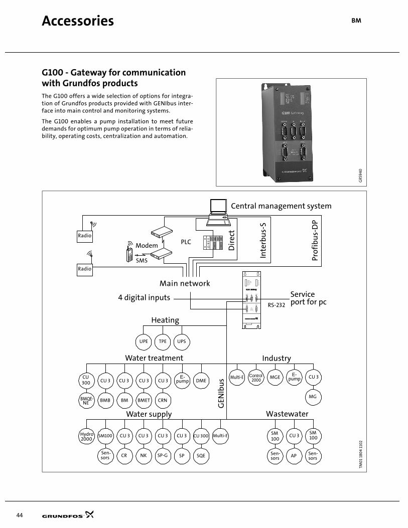
44
Accessories BM
G100 - Gateway for communication with Grundfos productsThe G100 offers a wide selection of options for integra-tion of Grundfos products provided with GENIbus inter-face into main control and monitoring systems.
The G100 enables a pump installation to meet futuredemands for optimum pump operation in terms of relia-bility, operating costs, centralization and automation.
GR5
940
G10
0TM
01
180
4 11
02
Port 1
Main
Network
Connection
POWERPOWER MNCPOWER GENIGENI TxDGENI RxDFAULT
DCDRTSTxD1RxD1TxD2RxD2
Port 2
Genibus DI Service
SM100 CU 3 CU 3 CU 3 CU 3
CR NK SP-G SPSen-sors
CU 3SM
Sen-sorsAP
E-pump CU 3
MG
Wastewater
Industry
RS-232
Serviceport for pc
Inte
rbu
s-S
Dir
ect
PLCModem
Hydro2000
Prof
ibu
s-D
P
Water supply
Control2000
MGE
UPE TPE UPS
4 digital inputs
Heating
SM
CU 3 CU 3 CU 3
BM BMET CRN
Water treatment
GEN
Ibu
sCU 3
BMB
CU 300
SQE
100 100
Sen-sors
BMQE-NE
CU300
Multi-EDME
Multi-E
Main network
Radio
Radio
SMS
E-pump
Central management system

45
Accessories BM
Product descriptionThe G100 Gateway enables communication of operatingdata, such as measured values, setpoints, etc., betweenGrundfos products with GENIbus interface and a mainnetwork for control and monitoring.
As indicated in the illustration on page 44, the G100 issuitable for use in applications such as water supply,water treatment, wastewater, building automation andindustry.
Common to above applications is that downtime isusually costly, and extra investments are therefore oftenmade to achieve maximum reliability by monitoringselected operating variables.
The day-to-day operation, such as starting and stoppingof pumps, changing of setpoints, etc., can also beeffected from the main system by communication withthe G100. In addition, the G100 can be set up to sendevent-controlled status indications such as alarms viathe SMS to mobile phones, and to make automatic alarmcall-backs to a central management system.
Data loggingBesides the possibility of data communication, the G100also offers logging of up to 350,000 time-stamped data.Subsequently, the logged data can be transmitted to themain system or a PC for further analysis in a spreadsheetor similar program.
For the data logging, the "PC Tool G100 Data Log" soft-ware tool is used. The tool is part of the PC Tool G100package, which must be ordered separately.
Other features• Four digital inputs.
• Stop of all pumps in case of failing communication with the management system (optional).
• Access code for modem communication (optional).
• Alarm log.
InstallationInstallation of the G100 is effected by the system inte-grator. The G100 is connected to the GENIbus as well asto the main network. Subsequently, all units on theGENIbus can be controlled from a central managementsystem on the main network.
The "G100 Support Files" CD-ROM supplied with theG100 contains examples of programs to be used whenthe G100 is connected to the various main networksystems. Included is also a description of the data pointsavailable in Grundfos products with GENIbus interface.The "PC Tool G100" software tool can be used for theG100 installation and use. To be ordered separately.
Technical data
Overview of protocols
Other possible connections
GENIbus RS-485: Connection of up to 32 units.
Service port RS-232: For direct connection to a PC
or via radio modem.Digital inputs: 4.
Voltage supply: 1 x 110-240 V, 50/60 Hz
Ambient temperature: In operation:–20°C to +60°C (–4°F to +140°F)
Enclosure class: IP 20
Weight: 1.8 kg (4.0 lbs).
Accessories• PC Tool G100 package (to be ordered separately)
• G100 Support Files CD-ROM (supplied with product)
Product numbers
*Floppy disk with G100 Support Files included.
TM0
1 0
621
110
2
Main system Software protocol
INTERBUS-S PCP
PROFIBUS-DP DP
Radio Satt Control COMLI/Modbus
Modem Satt Control COMLI/Modbus
PLC Satt Control COMLI/Modbus
GSM mobile phone SMS, UCP
ProductProductnumber
G100 with Interbus-S expansion board* 96411134
G100 with Profibus-DP expansion board* 96411135
G100 with Radio/Modem/PLC-expansion board* 96411136
G100 Basic Version* 96411137
PC Tool G100 package 96415783
73 mm 165 mm
227
mm
Port 1
Main
Network
Connection
POWER
POWER MNC
POWER GENI
GENI TxD
GENI RxD
FAULT
DCD
RTS
TxD1
RxD1
TxD2
RxD2
Port 2
Genibus DI Service
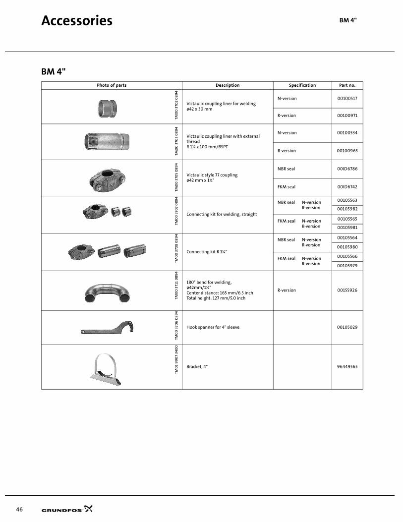
46
Accessories BM 4"
BM 4"Photo of parts Description Specification Part no.
TM0
0 3
702
08
94
Victaulic coupling liner for weldingø42 x 30 mm
N-version 00100517
R-version 00100971
TM0
0 3
703
08
94
Victaulic coupling liner with external threadR 1¼ x 100 mm/BSPT
N-version 00100534
R-version 00100965
TM0
0 3
705
089
4Victaulic style 77 couplingø42 mm x 1¼"
NBR seal 00ID6786
FKM seal 00ID6742
TM0
0 3
707
089
4
Connecting kit for welding, straight
NBR seal N-versionR-version
00105563
00105982
FKM seal N-versionR-version
00105565
00105981
TM0
0 3
708
08
94
Connecting kit R 1¼"
NBR seal N-versionR-version
00105564
00105980
FKM seal N-versionR-version
00105566
00105979
TM0
0 3
711
089
4
180° bend for welding,ø42mm/1¼"Center distance: 165 mm/6.5 inchTotal height: 127 mm/5.0 inch
R-version 00155926
TM0
0 3
706
089
4
Hook spanner for 4" sleeve 00105029
TM0
1 9
90
7 34
00
Bracket, 4" 96449565
Accessories BM 4”

47
Accessories BM 6"
BM 6"
BM 8"
Photo of parts Description Specification Part no.
TM0
0 3
709
08
94
Victaulic coupling liner for weldingø89 x 50 mm 3" x 2"
N-version 00150574
R-version 00140968
TM0
0 3
711
08
94 180° bend for welding,
ø89 mm/3"Center distance: 300 mm/11.8 inchTotal height: 210 mm/8.3 inch
N-version 00155544
R-version 00155971
TM0
0 3
712
08
94
Victaulic style 77 coupling, ø89 mm x 3" NBR seal 00ID7664TM
00
371
3 0
89
4
Hook spanner for 6" sleeve 00ID7669
TM0
0 3
714
08
94
Connecting kit for welding, straight
NBR seal, N-version 00155542
NBR seal, R-version 00155973
TM0
0 3
715
08
94
Connecting kit, 180°
NBR seal, N-version 00155543
NBR seal, R-version 00155972
TM0
1 9
90
7 34
00
Bracket, 6" 96449184
Photo of parts Description Specification Part no.
TM0
0 3
712
08
94 Victaulic style 77 coupling
3": ø89 mm4": ø114 mm5": ø139 mm6": ø168 mm
NBR seal 3" 00ID7664
NBR seal 4" 96415463
NBR seal 5" 96416739
NBR seal 6" 00ID2279
TM0
0 3
709
08
94
Victaulic coupling liner for welding
N-version 3" 00150574
N-version 4" 96416743
N-version 5" 96416744
N-version 6" 96416745
TM0
1 9
90
7 34
00
Bracket, 8" 96416762
Accessories BM 6", BM 8"
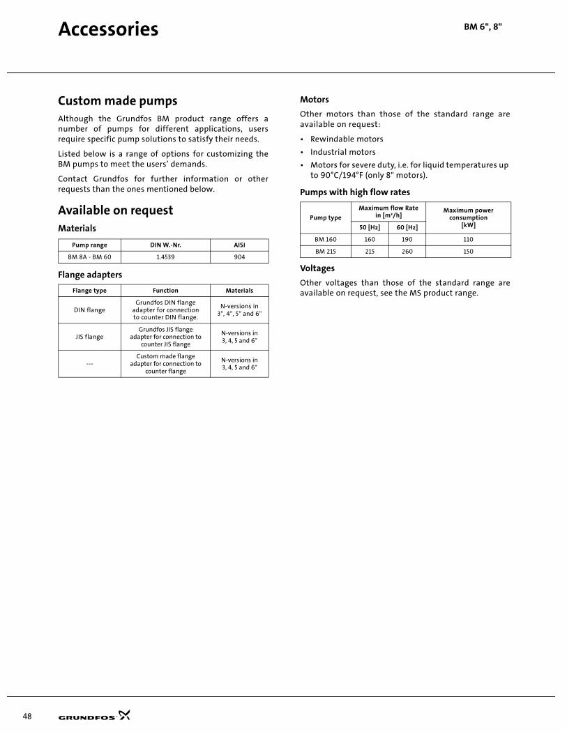
48
Custom made pumpsAlthough the Grundfos BM product range offers anumber of pumps for different applications, usersrequire specific pump solutions to satisfy their needs.
Listed below is a range of options for customizing theBM pumps to meet the users’ demands.
Contact Grundfos for further information or otherrequests than the ones mentioned below.
Available on requestMaterials
Flange adapters
Motors
Other motors than those of the standard range areavailable on request:
• Rewindable motors
• Industrial motors
• Motors for severe duty, i.e. for liquid temperatures up to 90°C/194°F (only 8" motors).
Pumps with high flow rates
Voltages
Other voltages than those of the standard range areavailable on request, see the MS product range.
Pump range DIN W.-Nr. AISI
BM 8A - BM 60 1.4539 904
Flange type Function Materials
DIN flangeGrundfos DIN flange
adapter for connectionto counter DIN flange.
N-versions in3", 4", 5" and 6"
JIS flangeGrundfos JIS flange
adapter for connection to counter JIS flange
N-versions in3, 4, 5 and 6"
---Custom made flange
adapter for connection to counter flange
N-versions in3, 4, 5 and 6"
Pump type
Maximum flow Ratein [m³/h]
Maximum power consumption
[kW]50 [Hz] 60 [Hz]
BM 160 160 190 110
BM 215 215 260 150
BM 6", 8"Accessories
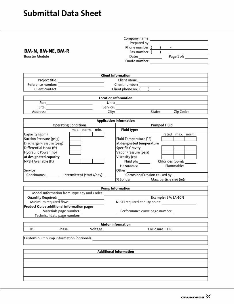
Submittal Data Sheet
Company name:Prepared by:
Phone number: ( ) -Fax number: ( ) -
Booster Module Date: Page 1 of:Quote number:
Project title: Client name:Reference number: Client number:
Client contact: Client phone no: ( ) -
For: Unit:Site: Service:
Address: City: State: Zip Code:
max. norm. min. Fluid type:Capacity (gpm) rated max. norm.Suction Pressure (psig) Fluid Temperature (°F)Discharge Pressure (psig) at designated temperatureDifferential Head (ft) Specific GravityHydraulic Power (hp) Vapor Pressure (psia)at designated capacity Viscosity (cp)NPSH Available (ft) Fluid ph: Chlorides (ppm):
Hazardous: Flammable:Service Other:
Continuous: Intermittent (starts/day): Corrosion/Errosion caused by:% Solids: Max. particle size (in):
Model Information from Type Key and Codes:Quantity Required: Example: BM 3A-10N
Minimum required flow: NPSH required at duty point:Product Guide additional information pages
Materials page number: Performance curve page number:Technical data page number:
HP: Phase: Voltage: Enclosure: TEFC
Custom-built pump information (optional):
BM-N, BM-NE, BM-R
Location Information
Client Information
Additional Information
Application Information
Pump Information
Motor Information
Pumped FluidOperating Conditions

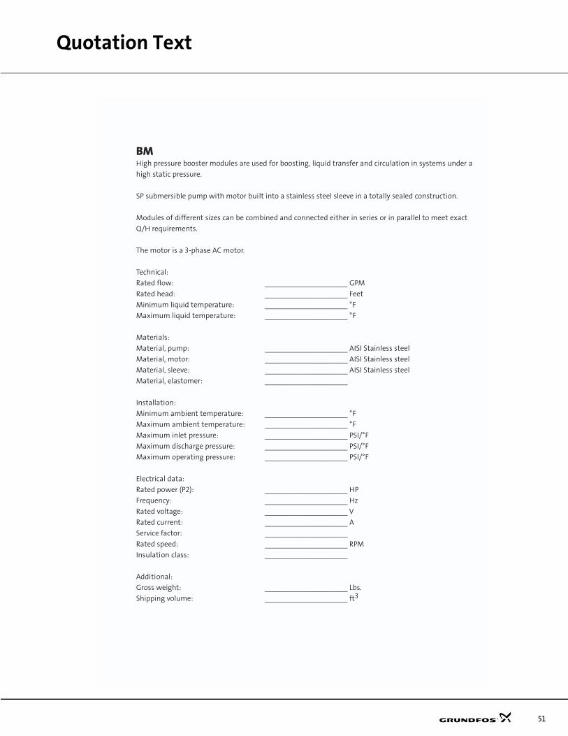
Quotation Text
51
BMHigh pressure booster modules are used for boosting, liquid transfer and circulation in systems under a
high static pressure.
SP submersible pump with motor built into a stainless steel sleeve in a totally sealed construction.
Modules of different sizes can be combined and connected either in series or in parallel to meet exact
Q/H requirements.
The motor is a 3-phase AC motor.
Technical:
Rated flow: ____________________ GPM
Rated head: ____________________ Feet
Minimum liquid temperature: ____________________ °F
Maximum liquid temperature: ____________________ °F
Materials:
Material, pump: ____________________ AISI Stainless steel
Material, motor: ____________________ AISI Stainless steel
Material, sleeve: ____________________ AISI Stainless steel
Material, elastomer: ____________________
Installation:
Minimum ambient temperature: ____________________ °F
Maximum ambient temperature: ____________________ °F
Maximum inlet pressure: ____________________ PSI/°F
Maximum discharge pressure: ____________________ PSI/°F
Maximum operating pressure: ____________________ PSI/°F
Electrical data:
Rated power (P2): ____________________ HP
Frequency: ____________________ Hz
Rated voltage: ____________________ V
Rated current: ____________________ A
Service factor: ____________________
Rated speed: ____________________ RPM
Insulation class: ____________________
Additional:
Gross weight: ____________________ Lbs.
Shipping volume: ____________________ ft3
GRUNDFOS Pumps Corporation 17100 West 118th TerraceOlathe, Kansas 66061
GRUNDFOS Canada Inc. 2941 Brighton Road Oakville, Ontario L6H 6C9 CanadaPhone: 905 829 9533 Telefax: 905 829 9512
Bombas GRUNDFOS de Mexico S.A. de C.V. Boulevard TLC No. 15Parque Industrial Stiva AeropuertoApodaca, N.L. Mexico 66600Phone: 52-81-8144 4000 Telefax: 52-81-8144 4010www.grundfos.com
Subject to alterations.
Being responsible is our foundationThinking ahead makes it possible
Innovation is the essence
Phone: 913 227 3400
Fax: 913 227 3500
L-BM-PG-002 2/03PRINTED IN USA