Embed Size (px)
Citation preview
An Assembler for a Small Computer
An Honors Thesis (HONRS 499)
by
Erin M. Vertrees
Dr. Ralph L. Place
Qf!; lV~ signed
Ball State University
Muncie, Indiana
May 1999
May 8,1999
..
Abstract i '~11 • ylf-7
This discussion of an assembler for a small computer describes the different
instructions that are used by the computer and how these instructions are converted from
a symbolic form that is easier for people to write into the binary form that the computer
requires. The assembler program included with this discussion reads symbolic codes
from a text file and converts them into binary code to be sent to the small computer. The
computer itself is based upon the basic computer design outlined in chapter five ofM.
Morris Mano' s book, Computer System Architecture, and uses a very reduced set of
instructions, compared to normal desktop computers, to carry out operations involving
arithmetic and logic functions.
Acknowledgements
Thank you to Dr. Ralph L. Place, my thesis advisor, who presented me with this
project idea and gave me the opportunities to present it to my peers at the Computer
Science Open House and at the Undergraduate Research Conference at Butler University.
Also, thank you to my fiance, J. Eric Bockelman, who lent me his programming expertise
and development software.
-
An Assembler for a Small Computer
The assembler for a small computer is part of a larger project that was undertaken
by two other students and myself as honors fellowships. For the fall semester of 1998,
Dr. Ralph L. Place proposed that the small computer design found in chapter five of M.
Morris Mano's book, Computer System Architecture, be built. Once it was finished, a
method for giving the small computer tasks to complete was needed. The small computer
does not have the traditional method for input and output, such as a monitor and keyboard
that normal desktop computers have. Instructions have to be given to the small computer
directly in binary format, which is in the form of 0' sand l' s, rather than symbols that
people can understand. Therefore, it became my project to develop the assembler
software for the small computer.
A computer program is a sequence of instructions that tell the computer what
tasks to perform. The language of a program can take a variety of forms, such as
machine language, symbolic or assembler language, and high-level language. Machine
language instructions are in binary code and are an exact representation of instructions as
they appear in computer memory. With symbolic code, the programmer uses symbols
consisting of letters, numbers, and special characters, for each of the computer's
instructions. E~ch symbolic instruction can be translated directly into a single binary
instruction. A special program called an assembler translates the symbolic codes into the
binary codes that the computer can understand. As a result, symbolic code is also called
assembly language. High-level language programs reflect the procedures used in the
2
solution of a problem rather than with computer hardware. The program that translates a
high-level language program to binary is called a compiler (Mano 174-176).
Before describing the assembly process, a description of the different kinds of
computer instructions and their binary representation is necessary. There are four
different types of computer instructions in the assembly language for the small computer.
These instructions are memory reference instructions, register reference instructions,
input/output instructions, and pseudoinstructions. This fourth group, however, consists of
instructions that are not computer instructions but are instructions that give the assembler
information about the phase of translation (Mano 180). Each of the other three sets of
instructions has a specific code format consisting of sixteen bits. Each bit is a binary
digit, zero or one (Mano 132).
Memory reference instructions are computer instructions that do exactly as their
name suggests. These instructions reference the computer's memory for data to process.
The sixteen-bit instruction code for memory reference instructions consists of three parts.
Bits four through fifteen contain the binary address of the data to be processed. This
twelve-bit address specifies the location in the computer's memory where the data can be
found. Bits one through three contain the three-bit operation code that represents the
specific memory reference instruction to be executed. The zero bit is called the
addressing mode bit. If this bit is set to zero, then the address part of the instruction is
called a direct address meaning that this is the address in memory where the data to be
processed can be found. If the mode bit is set to one, then the address part of the
instruction is called an indirect address. An indirect address specifies the memory
-
-
location that contains the address where the data to be processed can be found. It is the
address of the address, so to speak (Mano 132).
3
Regist(~r reference instructions and input/output instructions have similar
instruction code formats and are grouped together in a category called non-memory
reference instructions. Register reference instructions perform operations or tests on the
accumulator n~gister of the small computer. Input/output instructions are needed for
bringing infonnation in and out ofthe small computer. The sixteen-bit instruction code
format of the register reference instructions consists of two parts. Bits four through
fifteen represent the register operation to be performed. Bits zero through three identify
the instruction as a register reference instruction and always have the value of 0111. The
sixteen-bit instruction code for input/output instructions also consists of two parts. Bits
four through f[fteen represent the input/output operation to be performed. Bits zero
through three identify the instruction as an input/output instruction and always have the
value of 1111 (Mano 132).
Pseudoinstructions, as stated earlier, are not true computer instructions. Instead,
they are instructions to the assembler about the phase ofthe binary translation. There are
four different pseudoinstructions that are used by the assembler for the small computer.
The first is the ORG, or origin, pseudoinstruction. This pseudoinstruction informs the
assembler that the instruction or operand in the next line of the program is to be placed in
the memory location specified by the number that follows the ORG instruction. The next
pseudoinstruction is the END pseudoinstruction. END is placed at the end of the
symbolic program and tells the assembler that there are no more lines in the program to
translate. The final two pseudoinstructions, DEC and HEX, tell the assembler how to
-
-
convert the number that follows into a binary number. If the pseudoinstruction is DEC,
the number must be converted from a decimal format to binary. If the pseudoinstruction
is HEX, then the number that follows must be converted from a hexadecimal format to
binary (Mano 180 - 181).
4
Like all languages, programming languages have rules concerning how the
instructions ar,e used when writing programs. The assembly language for the small
computer also has its own set of rules that must be followed in order for the assembler to
correctly translate the symbolic instructions to the sixteen-bit binary instruction codes.
Each assembly program written for the small computer must contain three columns or
fields that are separated by tabs. The first field is the label field. This field may be
empty, or it may specify a symbolic address, or variable name, that will represent a
specific location in the computer's memory. The symbolic address can consist of one to
three alphanumeric characters, and a comma must always terminate it. The programmer
may determine what this symbol is (Mano 179).
The second field in the assembly program is the instruction field. The instruction
field specifies a machine instruction or a pseudo instruction. If the instruction is a
memory reference instruction, then it occupies two or three symbols that are separated by
spaces. The first symbol must be one of the three letter symbols that specify a memory
reference operation. The second symbol is one of the symbolic addresses that were
defined by the programmer. Each symbolic address that appears in the instruction field,
then it must appear again in the label field. The third symbol is optional, and if present, it
must be the letter 1. If the I symbol is present, this symbol specifies an indirect address.
If it is missing, then it specifies a direct address. If the instruction is a non-memory
-5
reference instruction, it must specify any of the three letter symbols for register reference
instructions or input/output instructions. The third field in the assembly program is the
comment field, which may be used or left blank. During the binary translation process of
the assembler, the comment field is ignored. Comments are for explanation purposes
only and help the programmer to describe what each line of his program is doing. In
order for the assembler to recognize the comment, it must be preceded by a forward slash
(Mano 179 - 181).
What follows is an example of an assembly program for the small computer that
will subtract two numbers.
MIN, SUB, DIF,
ORG 100 LDASUB CMA INC ADD MIN STADIF HLT DEC 83 DEC-23 HEX 0 END
IOrigin of program is location 100 !Load subtrahend to AC ICompiement AC IIncrement AC IAdd minuend to AC IStore difference !Halt computer !Minuend ISubtrahend !Difference stored here lEnd of symbolic program
The first line of the program contains the pseudo instruction ORG and defines the origin
of the program at the memory location 10016. The next six lines define machine
instructions that actually perform the subtraction. The last four lines contain
pseudo instructions. Three symbolic addresses have been defined in the label field and
can be found again in the instruction field as operands of memory reference instructions.
In the last four lines, three of the pseudo instructions specify operands to be converted to
binary, and the last specifies the end of the symbolic program (Mano 181).
Once an understanding of how the assembler instructions are represented in their
binary format is acquired, the assembly process can be discussed. The assembly process
-6
that translates the symbolic program to binary code is a two step process meaning that the
assembler scans the symbolic program twice in order generate the binary code. The first
pass of the assembly generates a table that correlates the user-defined address symbols
with their binary equivalent value. There is no translation of the program to binary code
during the first pass ofthe assembler. This is done during the second pass. To keep track
of the memory location of each instruction, the assembler uses a location counter (LC).
The LC stores the value of the memory location assigned to the instruction or operand
that is currently being processed. The ORG pseudoinstruction initializes the LC to the
value of the first location. Since the instructions are stored in sequential locations, the
content ofLC is incremented by one after processing each line of code. In case the ORG
statement is missing, the assembler initially sets the LC to zero (Mano 185-186).
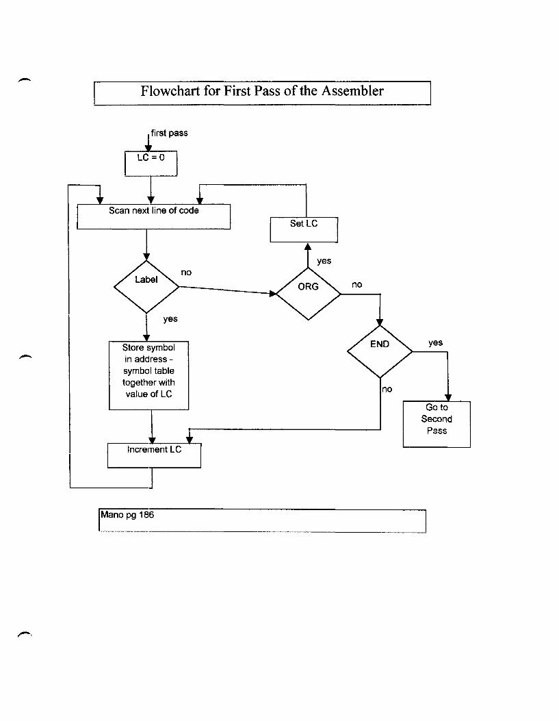
During the first pass, the assembler performs a series of tasks to generate the
symbolic address table. The assembler examines each line of code in the symbolic
program to determine if that line contains a label. If the line does not have a label, then
the assembler checks the line for the pseudo instructions ORG or END. If an ORG is
encountered, the LC is initialized with the value of the number that follows and goes on
to process the next line. If an END is encountered, the assembler terminates the first pass
and begins the: second pass. If the line of code contains a label, it is stored in the address
symbol table with its binary equivalent of the number that is stored in LC. The LC is
then incremented by one and the next line of code is processed (Mano 185-186).
The second pass of the assembly process is where the actual translation from the
symbolic code: to the binary code takes place. The translation process takes place through
a table-lookup procedure. The assembler will search each of three tables to find a
7
specific instruction and its binary equivalent. Any symbol that is used in the program
must be found in one of the lookup tables. If it cannot be found, the symbol cannot be
translated. The three lookup tables are the MRI (memory reference instruction) table, the
Non-MRI (non-memory reference instruction) table, and the address symbol table. The
MRI table contains the seven symbols of the memory reference instructions and their
three-bit binary codes. The Non-MRI table contains the symbols for the eighteen register
reference instructions and input/output instructions with their sixteen-bit binary codes.
The address table is generated during the first pass of the assembly process (Mano 187).
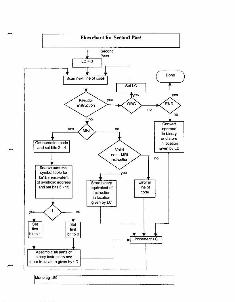
The se4;::ond pass of the assembler performs a series of tasks to translate the
symbolic code to binary code. The LC is initially set to zero. The label field is ignored
during the second pass; therefore, the assembler checks the first symbol in the instruction
field of the program. First, the assembler checks to see if the symbol encountered is a
pseudo instruction. If the symbol is ORG, the LC is initialized with the value following
the ORG statement. If END is encountered, the translation process is terminated. An
operand pseudo instruction, DEC or HEX, causes a conversion of the operand into binary.
The operand is then written to a file that will contain the translated binary instructions.
These instructions will be stored in the memory location of the small computer that is
specified by the LC. The location counter is incremented by one, and the next line of the
assembler program is processed (Mano 188).
If the instruction being processed is not a pseudoinstruction, the MRI table is
checked next. If the instruction is found in this table, the three-bit code is extracted from
the table and is inserted into bits one through three of the sixteen-bit instruction code.
Since a memory reference instruction is specified by two or three symbols, the second
-
-
8
symbol, the address symbol, is processed. The assembler then checks the address symbol
table. If the symbol is found, the twelve bit binary address is inserted into bits four
through fifteen. Next the assembler checks for the presence of the optional I symbol. If
the I symbol is present, bit zero of the sixteen-bit instruction code is set to one. If the I
symbol is not present, then bit zero is set to zero. Once the three parts of the sixteen-bit
instruction have been assembled, the binary instruction is written to the binary code file.
The LC is incremented, and the next line of the program is processed. If the symbol is
not found in the address table, then the address was not specified in the label field of the
program. The assembly process will terminate with an error message telling the
programmer that the address symbol could not be found (Mano 188).
If the symbol being processed was not a pseudoinstruction or a memory reference
instruction, the assembler checks the Non-MRI table. If the symbol is found in this table,
the sixteen-bit instruction code is extracted and written to the binary code file. The
location counter is incremented, and the assembler processes the next line of code. If the
symbol is not found in this table, then this does not exist in any of the tables. The
assembler will terminate and display a message to the programmer that the assembly
code could not be found and the line number where the error occurred (Mano 188).
Through this project, I have gained a greater understanding of how computer
instructions are stored in the computer's memory. When I first received this project, I did
not expect it to be as large as it was. Before I could do any programming, I had to
research how the computer instructions are assembled into binary instructions for the
small computer. I then had to research the process that the assembler uses to do these
translations. My assembler program was written using Visual C++ 6.0. Along with the
-9
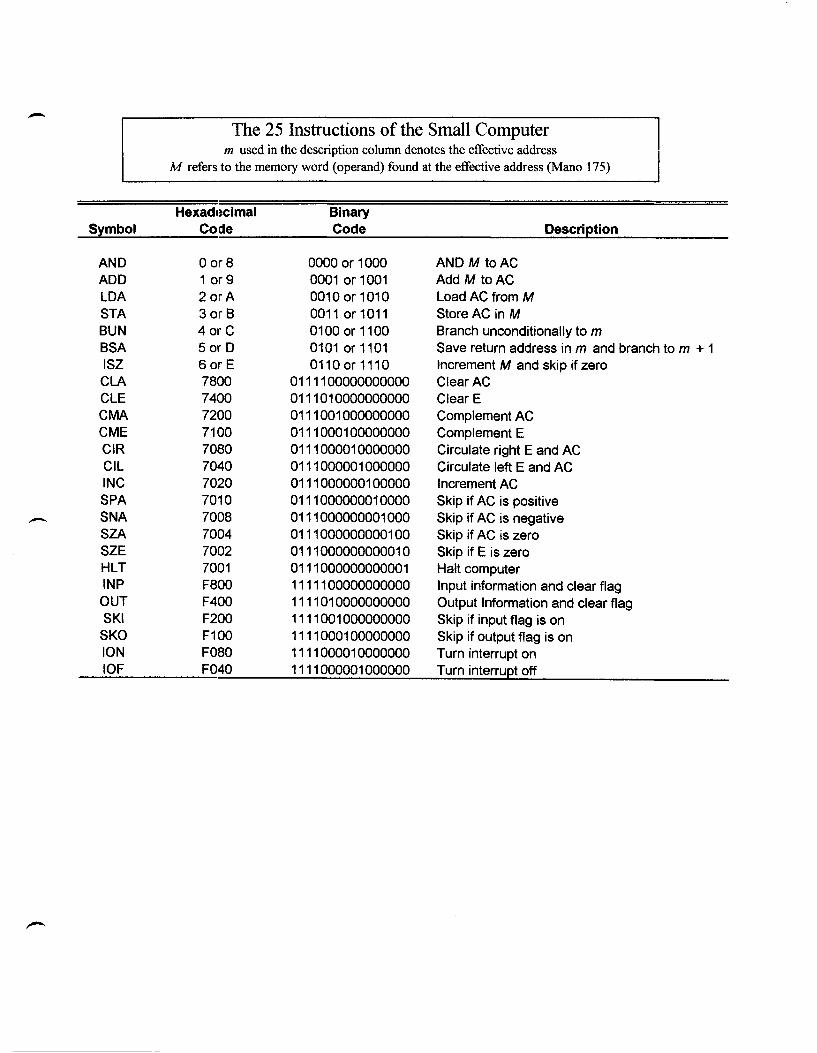
executable program, there are two files that contain the memory reference and non
memory reference instructions and their binary equivalents. The assembler program
searches these files when processing an assembler program. The following page lists the
instructions used by the small computer along with their hexadecimal and binary
equivalents. A short description accompanies each three-letter instruction code. The
next two pages show the flowcharts from Mano' s text that were used as a basis for the
assembler program. The final page lists specific instructions for using the assembler
program.
- The 25 Instructions of the Small Computer m used in the description column denotes the effective address
M refers to the memory word (operand) found at the effective address (Mano 175)
Hexadecimal Binary Symbol Code Code Description
AND o or8 0000 or 1000 AND M toAC ADD 1 or 9 0001 or 1001 Add M toAC lOA 2 orA 0010 or 1010 load AC from M STA 3 or B 0011 or 1011 StoreAC in M BUN 4mC 0100 or 1100 Branch unconditionally to m BSA 5 or 0 0101 or 1101 Save return address in m and branch to m + 1 ISZ 6 or E 01100r 1110 Increment M and skip if zero CLA 7800 0111100000000000 ClearAC ClE 7400 0111010000000000 Clear E CMA 7200 0111001000000000 Complement AC CME 7100 0111000100000000 Complement E CIR 70BO 0111000010000000 Circulate right E and AC Cil 7040 0111000001000000 Circulate left E and AC INC 7020 0111000000100000 Increment AC SPA 7010 0111000000010000 Skip if AC is positive - SNA 7008 0111000000001000 Skip if AC is negative SZA 7004 0111000000000100 Skip if AC is zero SZE 7002 0111000000000010 Skip if E is zero HlT 7001 0111000000000001 Halt computer INP F800 1111100000000000 Input information and clear flag OUT F400 1111010000000000 Output Information and clear flag SKI F200 1111001000000000 Skip if input flag is on SKO F100 1111000100000000 Skip if output flag is on ION F080 1111000010000000 Turn interrupt on IOF F040 1111000001000000 Turn interrupt off
Flowchart for First Pass of the Assembler
~ss
L:J
yes
Store symbol in addresssymbol table together with value of LC
IMano pg 186
no no
no
yes
Go to Second
Pass
-
yes
Get operation code I and set bits 2 - 4
Search addresssymbol table for
binary equivalent of symbolic address and set bits 5 - 16
first bit to 1
first bit to 0
Assemble all pclrts of binary instruction and
store in location given by lC
IMano pg 189
Flowchart for Second Pass
Second
Store binary equivalent of
instruction in location
given by lC
SetlC
Error in line of code
, ......
no
operand to binary and store in location
given by lC
.-
Installation: 1. 2. 3. 4.
5. 6.
UninstalJ: 1.
2. 3. 4.
Source Code:
Rules for the Assembler
Double click setup.exe on the installation disk To cancel setup click cancel at any time Click next on the welcome screen Setup will suggest a location for the Assembler program or the user may click browse to select an alternative location Click next to continue with installation Installation is complete
To remove the program from the system, double click AddlRemove programs in the Control Panel Select Assembler from the list and click the AddlRemove button Click yes to confirm the removal of the Assembler from the system Click OK to complete the removal process
1. The source code and related workspace files are on the Assembly source disk
2. Copy all necessary files from the disk to a directory on the hard drive 3. These files include: asmcore.cpp, asmcore.h, guiassembler.cpp,
guiassembler.h, guiassembler.rc, guiassemblerDoc.cpp, guiassemblerDoc.h, guiassemblerView.cpp, guiassemblerView.h, MainFrm.cpp, MainFrm.h, resource.h, StdAfx.cpp, StdAfx.h, mri. txt, nonmri.txt, guiassembler.dsp, guiassembler.dsw
4. In Visual C++ open the guiassembler.dsw workspace file 5. The files mri. txt and nonmri. txt must exist in the same directory as the
executable for the program to work correctly
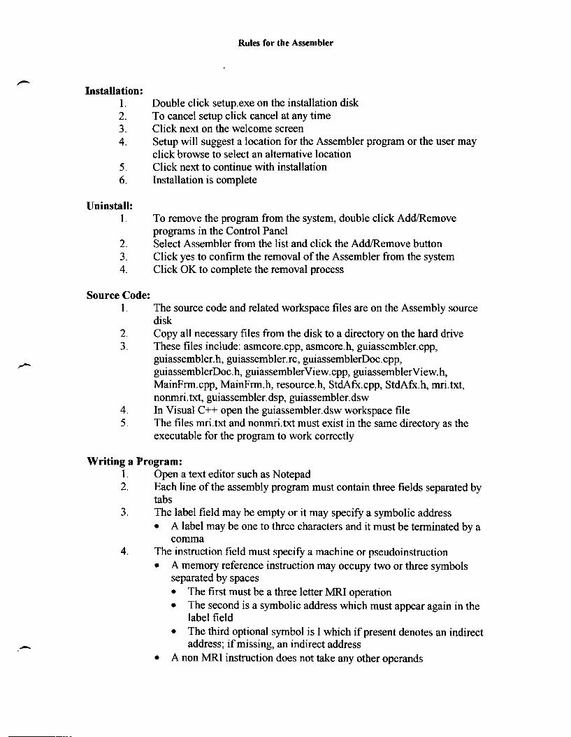
Writing a Program: 1. Open a text editor such as Notepad 2. Each line of the assembly program must contain three fields separated by
tabs 3.
4.
The label field may be empty or it may specify a symbolic address • A label may be one to three characters and it must be terminated by a
comma The instruction field must specity a machine or pseudoinstruction • A memory reference instruction may occupy two or three symbols
separated by spaces • The first must be a three letter MRI operation • The second is a symbolic address which must appear again in the
label field • The third optional symbol is I which if present denotes an indirect
address; if missing, an indirect address • A non MRI instruction does not take any other operands
,-
Rules for the Assembler
• The pseudoinstruction ORG must be followed by the Hex address of the starting location in memory where the program will be stored. This is the first line of the program
• The pseudoinstruction DEC or HEX must be followed by a decimal or hexadecimal operand
• The pseudo instruction END must be the last statement of the program 5. The program must be written in all capital letters for the assembler to
work properly 6. Please see example programs, subtracttxt, multiply. txt, subroutine.txt, on
the source code disk
Using the Assembler: 1. Double click the assembler.exe icon to start the Assembler program 2. Click the file menu option and select Open to open an assembler program
for the assembly process 3. Using the open file menu select the file to be assembled and click OK 4. The save window will appear next suggesting a name for the assembled
file 5.
6.
7.
8.
The user may select a new name or accept the default and click OK to start the assembly process If any errors exist, the assembler will display a message box with the line number of the error, and the assembly process will tenninate If the assembly process is successful, the assembler will display a window telling the user where the assembled file can be found Click the exit button or select Exit from the File menu to exit the assembler program
Works Cited and Bibliography
Blaszczak, Mike. Professional MFC with Visual C++ 5. Birmingham: Wrox Press, 1997.
Mano, M. Mouis. Computer System Architecture. New Jersey: Prentice Hall, Inc., 1993.
MSDN Library. CD-ROM. Microsoft Press, 1998.
Prosise, Jeff. "Programming Windows 95 with MFC. Washington: Microsoft Press, 1996.


![©¾QF¾ 7DUDI +L]PHWOHUL NR !XOODUD WDELGLU · - 3 - $ !dáógdnl](https://img.pdfslide.net/doc/110x75/5fb49c293f99a126634ded47/qf-7dudi-lphwohul-nr-xoodud-wdelglu-3-dgdnl-.jpg)