Embed Size (px)
Citation preview
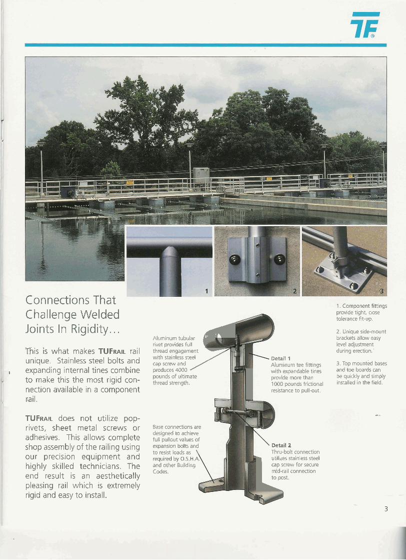
Connections l hat Challenge Welded Joints In Rigidity.. .
This is what makes TUFRAIL rail unique. Stainless steel bolts and
, expanding internal tines combine to make this the most rigid con- nection available in a component cail.
TUFRAIL does not utilize pop- rivets, sheet metal screws or adhesives. This allows complete shop assembly of the railing using our precision equipment and highly skilled technicians. The end result is an aesthetically pleasing rail which is extremely rigid and easy to install.
Aluminum tubular 4 rivet ~rovides full 1 threab engagement - with stainless steel cap screw and produces 4000
thread strength.
/ pounds of ultimate
Base connections are designed to achieve full pullout values of expansion bolts and to resist loads as
and other Building Codes.
provide'tight, close - tolerance fit-up.
2 . Unique sidemount brackets allow easy level adiustment during erection:
Detail 1 Aluminum tee fittings 3. TOP mounted bases
I with expandable tines and toe boards can provide more than be quickly and simply 1000 pounds frictional installed in the field. resistance to pull-out.
\ Detail 2 Thru-bolt connection utilizes stainless steel cap screw for secure mid-rail connection to post. L
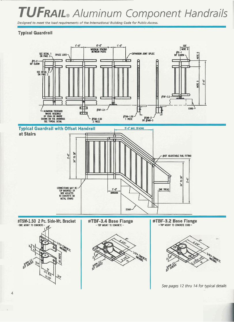
TUFRAIL, Aluminum Component Handrails Designed to meet the load requirements of the International Building Code for Public-Access.
Typical Guardrail
Typical Guardrail with Offset Handrail s a MAX, SAQNG i at Stairs
COMmM(S YAY BE T(IPYOUNTEDm rn YOUKlED
TOCONCRETEOR
#TBF-3.2 Base Flange -T(IPYOU(TTOCMlCRETECURB-
See pages 12 thru 14 for typical details
MTSM-1.50 2 PC. Side-Mt. Bracket - ~ Y O U l T l D ~
#TBF-3.4 Base Flange -TBYOMT~CO(CRETE-
International Building Code Design Specifications for Public-Access 1. Guardrails and Handrails shall be the product of a company normally engaged in the manufacture of pipe railing. Railings shall be shop assembled in lengths not to exceed 24 feet for field ' erection.
2. The handrail shall be made of pipes joined together with component fittings. Samples of all components, bases, toeboard and pipe must be submitted for approval at the request of the engineer. Components that are pop-riveted or glued at the joints will not be acceptable. All components must be mechanically fastened with stainless steel hardware. Handrail and components shall be TUFRAIL, as manufactured by Thompson Fabricating, LLC, Birmingham, AL or an approved equal.
3. Railings shall be 151" Schedule 40 aluminum pipe alloy 61 05-T5, ASTM-B-
I 429 or ASTM-6-221. Posts shall be I 1 IX" Schedule 80 aluminum pipe of the 1 same alloy. Post spacing shall be a I maximum of 6'-0". I
4. Guardrails and Handrails shall be designed to withstand a 2001b concen- trated load applied in any direction and at any point on the top rail. Guardrails and Handrails shall also be designed to with- stand a uniform load of 50 Iblft applied horizontally to the top rail. Uniform loads are not to be applied simultaneously with 1; the concentrated loads.
5. Pickets and intermediate railings shall be provided such that a 4-inch diameter
g, CAD D lesign Draw~ngs
tions are avai
sphere cannot pass through any opening up to a height of 34 inches. From a height of 34 inches to 42 inches above the adjacent walking surface, a sphere 8 inches in diameter shall not pass. The triangular openings formed by the riser, tread and bottom rail at the open side of a stairway shall be of a maximum size such that a sphere of 6 inches in diameter cannot pass through the opening.
6. Pickets and intermediate railings shall be designed to withstand a horizontally applied normal load of 501b on an area not to exceed one square foot including openings and spaces between rails.
7. The manufacturer shall submit calcu- lations for approval at the request of the Engineer. Testing of base castings or base extrusions by an independent lab or manufacturer's lab (if manufacturer's lab meets the requirements of the Aluminum Association) will be an acceptable substitute for calculations. Calculations will be required for approval of all other design aspects.
8. Posts shall not interrupt the continua- tion of the top rail at any point along the railing, including corners and end terminations (OSHA 191 0.23). The top surface of the top railing shall be smooth and shall not be interrupted by projected fittings.
9. The mid-rail at a corner return shall be able to withstand a 2OOlb load with- out loosening. The manufacturer is to determine this dimension for their
system and provide physical tests from a laboratory to confirm compliance.
10. Concrete anchors shall be stainless steel type 303 or 304 wedge anchors and shall be furnished by the handrail manufacturer. The anchor design shall include the appropriate reduction factors for spacing and edge distances in accordance with the manufacturers published data.
11. Toeboard shall conform to OSHA standards. Toeboard shall be a mini- mum of 4" high and shall be an extrusion that attaches to the posts with clamps that will allow for expansion and contraction between posts. Toeboards shall be set !4" above the walking surface. Toeboards shall be provided on handrails as required by OSHA andlor as shown on drawings. Toeboards shall be shipped in stock lengths for field installation.
12. A self-closing gate shall guard open- ings in the railing (OSHA 1910.23). Safety chains shall not be used unless specifically shown on the drawings.
13. Finish shall be Aluminum Association M I 0-C22-A41 (21 5-RI). The pipe shall be plastic-wrapped. The plastic wrap is to be removed after erection.
14. Aluminum surfaces in contact with concrete, grout or dissimilar metals shall be protected with a coat of bitumi- nous paint, Mylar isolators or other approved material.
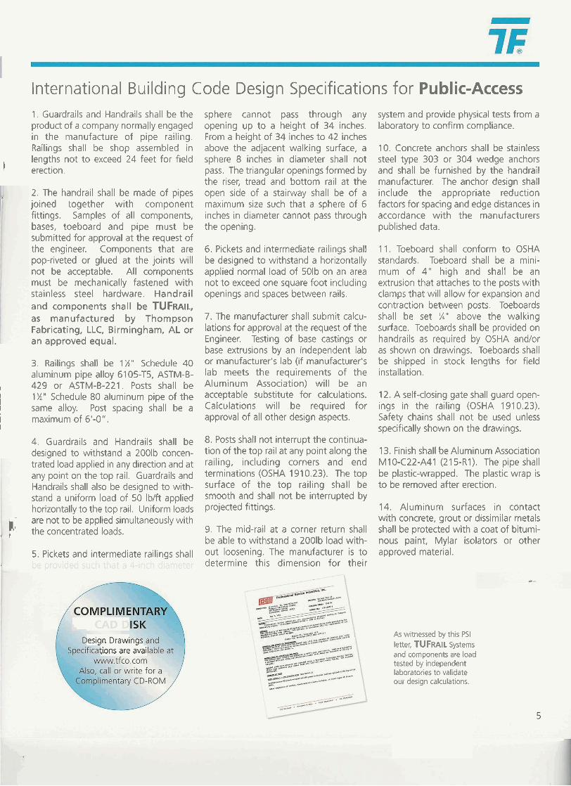
As witnessed by this PSI letter, TUFRAIL Systems and components are load tested by independent laboratories to validate our design calculations.
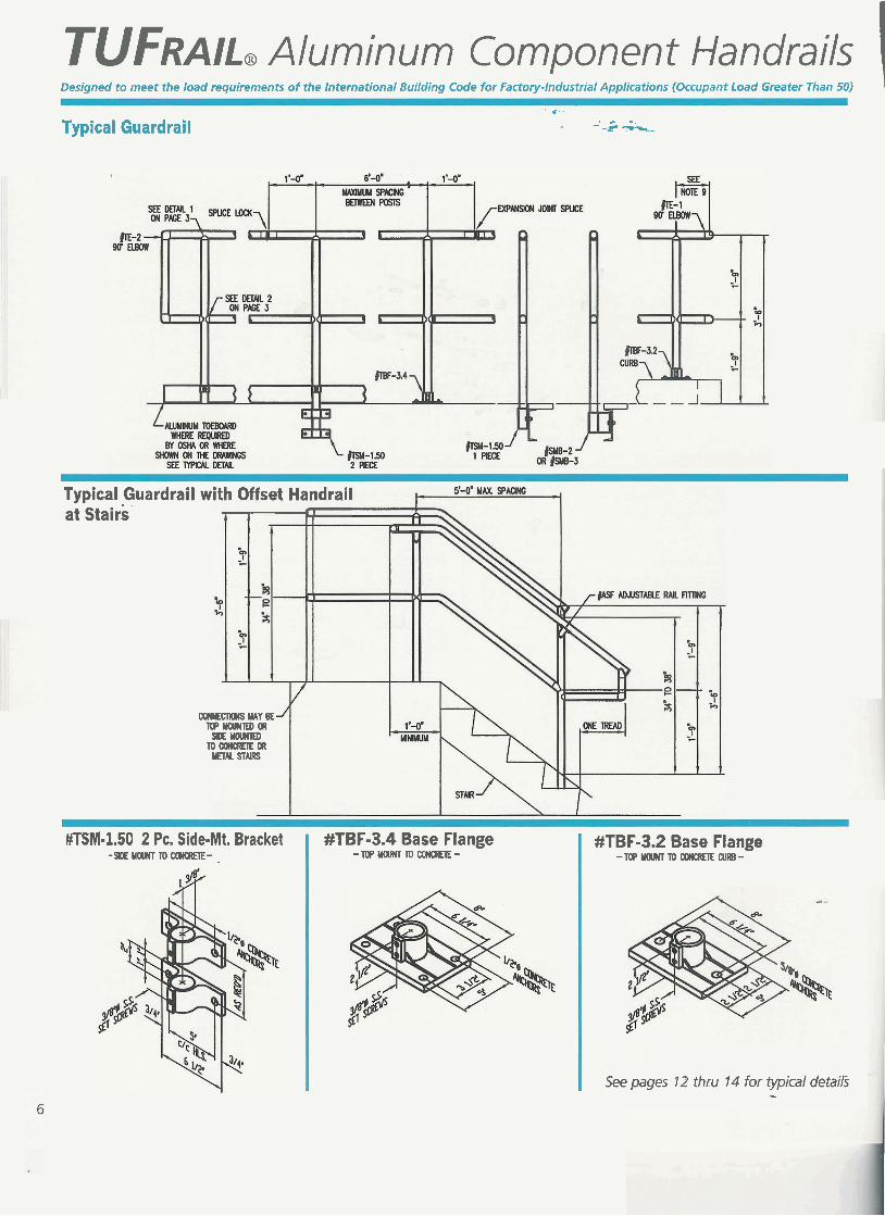
TUFRAIL, Aluminum Component Handrails 1 Designed to meet the load requirements of the International Building Code for Factory-Industrial Applications (Occupant Load Greater Than 50)
" *. . - -.
I Typical Guardrail - --- -%-
Typical Guardrail with Offset Handrail at stairs
alNEm MAY BE lwYOU(TEDOR
mu STUB
#TBF-3.2 Base Flange - l W Y O U l T ~ ~ C R E l E C U I -
See pages 12 thru 14 for typical details -
#TSM-1.50 2 PC. Side-Mt. Bracket -SIOEYOUNTTOM))(Q(EIE- -
#TBF-3.4 Base Flange -TOPUUmTTOCOWCI(EIE-
International Building Code Design Specifications for Factory- +'Industrial p; Applications (Occupant Load Greater Than 50)
1. ~uaidrails and Handrails shall be the withstand a uniform load of 50 Iblft 9. The mid-rail at a corner return shall be product of a company normally engaged applied horizontally to the top rail. able to withstand a 2001b load without in the manufacture of pipe railing. Uniform loads are not to be applied loosening. The manufacturer is to deter- Railings shall be shop assembled in simultaneously with the concentrated mine this dimension for their system and lengths not to exceed 24 feet for field loads. provide physical tests from a laboratory erection. to confirm compliance.
5. lntermediate railings shall be provided 2. The handrail shall be made of pipes such that a 21-inch diameter sphere 10. Concrete anchors shall be stainless joined together with component cannot pass through any opening. steel type 303 or 304 wedge anchors fittings. Samples of all components, and shall be furnished by the handrail bases, toeboard and pipe must be 6. lntermediate railings shall be designed manufacturer. The anchor design shall submitted for approval at the request of to withstand a horizontally applied include the appropriate reduction the engineer. Components that are normal load of 501b on an area not factors for spacing and edge distances in pop-riveted or glued at the joints will to exceed one square foot including accordance with the manufacturers not be acceptable. All components openings and spaces between rails. published data. must be mechanically fastened with stainless steel hardware. Handrail 7. The manufacturer shall submit calcu- 11. Toeboard shall conform to OSHA and components shall be TUFRAIL, lations for approval at the request of the standards. Toeboard shall be a mini- as manufactured by Thompson Engineer. Testing of base castings or mum of 4 " high and shall be an Fabricating, LLC, Birmingham, AL or base extrusions by an independent lab extrusion that attaches to the posts with an approved equal. or manufacturer's lab (if manufacturer's clamps that will allow for expansion and
lab meets the requirements of the contraction between posts. Toeboards 3. Railings shall be 1%" Schedule 40 alu- Aluminum Association) will be an shall be set %" above the walking minum pipe alloy 61 05-~5, A S T M - B - ~ ~ ~ acceptable substitute for calculations. surface. Toeboards shall be provided on or ASTM-B-~ZI. posts shall be 1%" Calculations will be required for handrails as required by OSHA andlor Schedule 80 aluminum pipe of the same approval of all other design aspects. as shown on drawings. Toeboards shall alloy, Post spacing shall be a maximum be shipped in stock lengths for field of 6'-0". 8. Posts shall not interrupt the continua- installation.
tion of the top rail at any point along the 4. Guardrails and Handrails shall be railing, including corners and end termi- 12. A self-closing gate shall guard open- designed to withstand a 2OOlb conr--n- nations (OSHA 191 0.23). The top ings in the railing (OSHA 191 0.23). trated load applied in any direction and surface of the top railing shall be Safety chains shall not be used unless at any point on the top rail, Guardrails smooth and shall not be interrupted by specifically shown on the drawings. and Handrails shall also be designed to projected fittings.
, , 13. Finish shall be Aluminum Association M I 0-C22-A41 (21 5-RI). The pipe shall be plastic-wrapped. The plastic wrap is to be removed after erection.
MPLIMENTAR 14. Aluminum surfaces in contact with concrete, grout or dissimilar metals shall be protected with a coat of bituminous paint, Mylar isolators or other approved
ations are available . . material.
As witnessed by this PTL- INSPECTORATE letter, TUFRAIL Systems and components are load tested by independent laboratories to validate our design calculations.
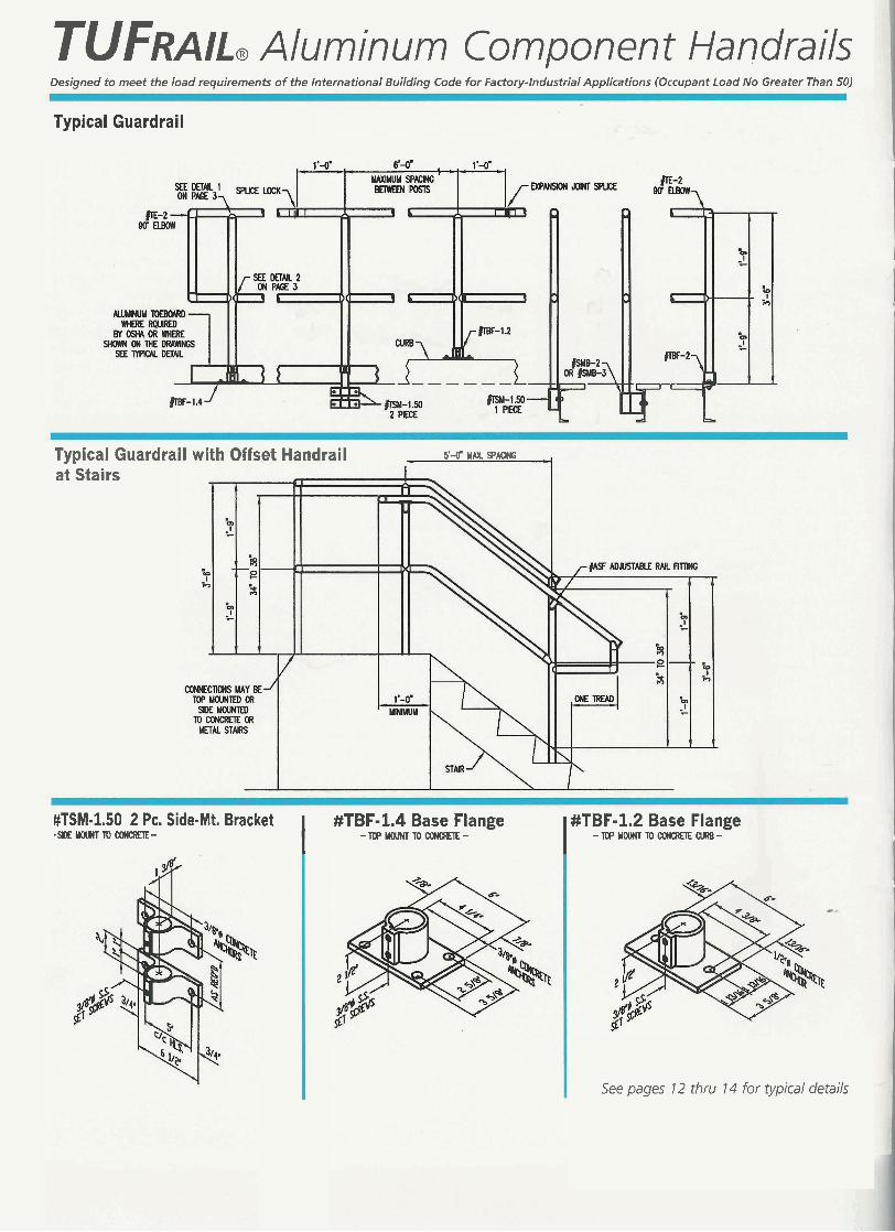
TUFRAIL, Aluminum Component Handrails Designed to meet the load requirements of the International Building Code for Factory-Industrial Applications (Occupant Load No Greater Than 50)
Typical Guardrail
Typical Guardrail with Offset Handrail 5 4 MAX SPMX
at Stairs
#TSM-1.50 2 PC. Side-Mt. Bracket I #TBF-1.4 Base Flange I #TBF-1.2 Base Flange -WEYMHTTOWWCREIE- -iOPYOUNTTOCONahTE- - lU'YWNTTOWWCREIECURB-
See pages 12 thru 14 for typical details
International Building Code Design Specifications for Factory- Industrial Applications (Occupant Load No Greater Than 50)
1. Guardrails and Handrails shall be the product of a company normally engaged in the manufacture of pipe railing. Railings shall be shop assembled in lengths not to exceed 24 feet for field erection.
2. The handrail shall be made of pipes joined together with component fit- tings. Samples of all components, bases, toe plate and pipe must be submitted for approval at the request of the engineer. Components that are pop-riveted or glued at the joints will not be acceptable. All components must be mechanically fastened with stainless steel hardware. Handrail and components shall be TUFRAIL, as manufactured by Thompson Fabricating, LLC, Birmingham, AL or an approved equal.
3. Railings shall be 1%" Schedule 40 alu- minum pipe alloy 61 05-T5, ASTM-B-429 or ASTM-B-221. Posts shall be 151" Schedule 40 aluminum pipe of the same alloy. Post spacing shall be a maximum of 6'-0".
4. Guardrails and Handrails shall be designed to withstand a 2001b concen- trated load applied in any direction and at any point on the top rail. Guardrails and Handrails shall also be designed to withstand a uniform load of 20 Iblft applied horizontally to the top rail. Uniform loads are not to be applied
simultaneously with the concentrated loads.
5. lntermediate railings shall be provided such that a 21-inch diameter sphere cannot pass through any opening.
6. lntermediate railings shall be designed to withstand a horizontally applied normal load of 501b on an area not to exceed one square foot including open- ings and spaces between rails.
7. The manufacturer shall submit calcu- lations for approval at the request of the Engineer. Testing of base castings or base extrusions by an independent lab or manufacturer's lab (if manufacturer's lab meets the requirements of the Aluminum Association) will be an acceptable substitute for calculations. Calculations will be required for approval of all other design aspects.
8. Posts shall not interrupt the continua- tion of the top rail at any point along the railing, including corners and end terminations (OSHA 191 0.23). The top surface of the top railing shall be smooth and shall not be interrupted by projected fittings.
9. The mid-rail at a corner return shall be able to withstand a 2001b load without loosening. The manufacturer is to deter- mine this dimension for their system and provide physical tests from a laboratory to confirm compliance.
10. Concrete anchors shall be stainless steel type 303 or 304 wedge anchors and shall be furnished by the handrail manufacturer. The anchor design shall include the appropriate reduction fac- tors for spacing and edge distances in accordance with the manufacturers pub- lished data.
11. Toeboard shall conform to OSHA standards. Toeboard shall be a minimum of 4" high and shall be an extrusion that attaches to the posts with clamps that will allow for expansion and contraction between posts. Toeboard shall be set % " above the walking surface. Toeboards shall be provided on handrails as required by OSHA and/or as shown on drawings. Toeboards shall be shipped in stock lengths for field installation.
12. A self-closing gate shall guard Openings in the railing (OSHA 1910.23). Safety chains shall not be used unless specifically shown on the drawings.
13. Finish shall be Aluminum Association M I 0-C22-A41 (21 5-RI). The pipe shall be plastic-wrapped. The plastic wrap is to be removed after erection.
14. Aluminum surfaces in contact with concrete, grout or dissimilar metals shall be protected with a coat of bituminous paint, Mylar isolators or other approved material.
Design Drawings arlu gifications are available at
or write for a Q ~ ~ X - U CD-ROM ,
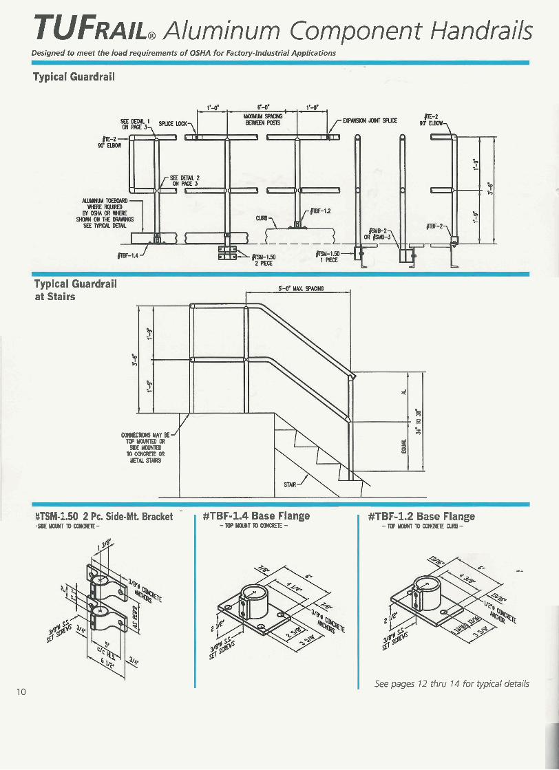
TUFRAIL, Aluminum Component Handrails Designed to meet the load requirements of OSHA for Factory-Industrial Applications
Typical Guardrail
Typical Guardrail at Stairs
d
COME- MAY BE-/ n]PYOUmDCR
SDE WlEO TOCONCRETEOR mu STARS
B
k B 3
-
MTSM-1.50 2 PC. Side-Mt. Bracket #TBF-1.4 Base Flange #TBF-1.2 Base Flange - S D E Y W W T T O ~ - - IOPWTTOawaEIE- - T O P Y M ] N T ~ ~ m -
a-
See pages 12 thru 14 for typical details
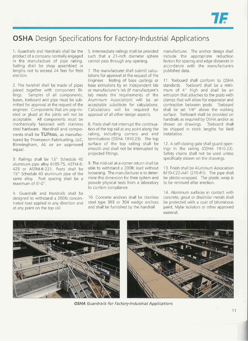
OSHA Design Specifications for Factory-Industrial Applications
1. Guardrails and Handrails shall be the product of a company normally engaged in the manufacture of pipe railing. Railing shall be shop assembled in lengths not to exceed 24 feet for field erection.
2. The handrail shall be made of pipes joined together with component fit- tings. Samples of all components, bases, toeboard and pipe must be sub- mitted for approval at the request of the engineer. Components that are pop-riv- eted or glued at the joints will not be acceptable. All components must be mechanically fastened with stainless steel hardware. Handrail and compo- nents shall be TUFRAIL, as manufac- tured by Thompson Fabricating, LLC, Birmingham, AL or an approved equal.
3. Railings shall be 1%" Schedule 40 aluminum pipe alloy 61 05-T5, ASTM-B- 429 or ASTM-B-221. Posts shall be 1 W " Schedule 40 aluminum pipe of the same alloy. Post spacing shall be a maximum of 6'-0".
4. Guardrails and Handrails shall be designed to withstand a 2OOlb concen- trated load applied in any direction and at any point on the top rail.
5. Intermediate railings shall be provided such that a 21-inch diameter sphere cannot pass through any opening.
7. The manufacturer shall submit calcu- lations for approval at the request of the Engineer. Testing of base castings or base extrusions by an independent lab or manufacturer's lab (if manufacturer's lab meets the requirements of the Aluminum Association) will be an acceptable substitute for calculations. Calculations will be required for approval of all other design aspects.
8. Posts shall not interrupt the continua- tion of the top rail at any point along the railing, including corners and end terminations (OSHA 191 0.23). The top surface of the top railing shall be smooth and shall not be interrupted by projected fittings.
9. The mid-rail at a corner return shall be able to withstand a 2001b load without loosening. The manufacturer is to deter- mine this dimension for their system and provide physical tests from a laboratory to confirm compliance.
10. Concrete anchors shall be stainless steel type 303 or 304 wedge anchors and shall be furnished by the handrail
manufacturer. The anchor design shall include the appropriate reduction factors for spacing and edge distances in accordance with the manufacturers published data.
11. Toeboard shall conform to OSHA standards. Toeboard shall be a mini- mum of 4" high and shall be an extrusion that attaches to the posts with clamps that will allow for expansion and contraction between posts. Toeboard shall be set 114" above the walking surface. Toeboard shall be provided on handrails as required by OSHA andlor as shown on drawings. Toeboard shall be shipped in stock lengths for field installation.
12. A self-closing gate shall guard open- ings in the railing (OSHA 1910.23). Safety chains shall not be used unless specifically shown on the drawings.
13. Finish shall be Aluminum Association M I 0-C22-A41 (21 5-RI). The pipe shall be plastic-wrapped. The plastic wrap is to be removed after erection.
14. Aluminum surfaces in contact with concrete, grout or dissimilar metals shall be protected with a coat of bituminous paint, Mylar isolators or other approved material.
OSHA Guardrails for Factory-Industrial Applications
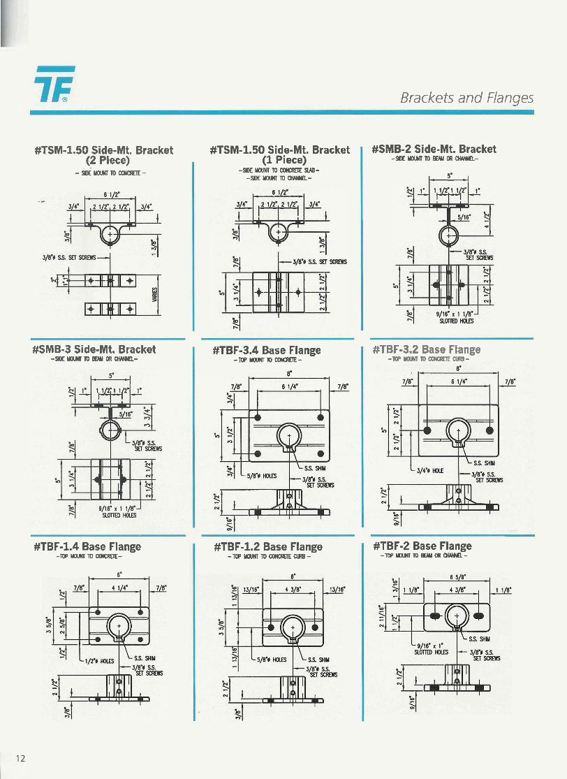
Brackets and Flanges
#TSM-1.50 Side-Mt. Bracket (2 Piece)
-&YOV)(ITOCONCREIE.-
#SMB-3 Side-Mt. Bracket -SIOEWU(ImwORQUHIEL-
#TBF-1.4 Base Flange -TwUWHTloCM(CREIE-
6'
#TSM-1.50 Side-Mt. Bracket (1 Piece)
-SDEYOVHlTOCO)(CREIESUB- -mWU(ImWwEL-
#TBF-3.4 Base Flange - m F ' Y W N l T O ~ -
#TBF-1.2 Base Flange -TOPUOUNlTO(XW(CREIEWRB-
#SMB-2 Side-Mt. Bracket - S W E ~ T O ~ a R c M m -
5. ,
#TBF-3.2 Base Flange - m P ~ l D ~ C U R B -
#TBF-2 Base Flange - T o P m m m o R c M H n -
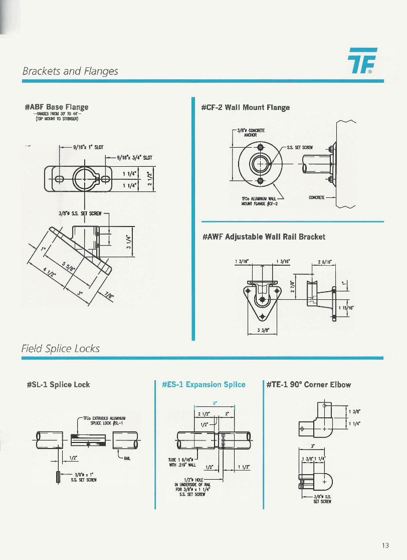
Brackets and Flanges
#ABF Base Flange -IW(GEfm3crfO44'- m ' ~ ~ - )
Field Splice Locks
#CF-2 Wall Mount Flange
#AWF Adjustable Wall Rail Bracket
1 3/16' , , 1 3/16. t-9
#SL-1 Splice Lock #ES-1 Expansion Splice
t- 5'
I
#TE-190" Corner El bow
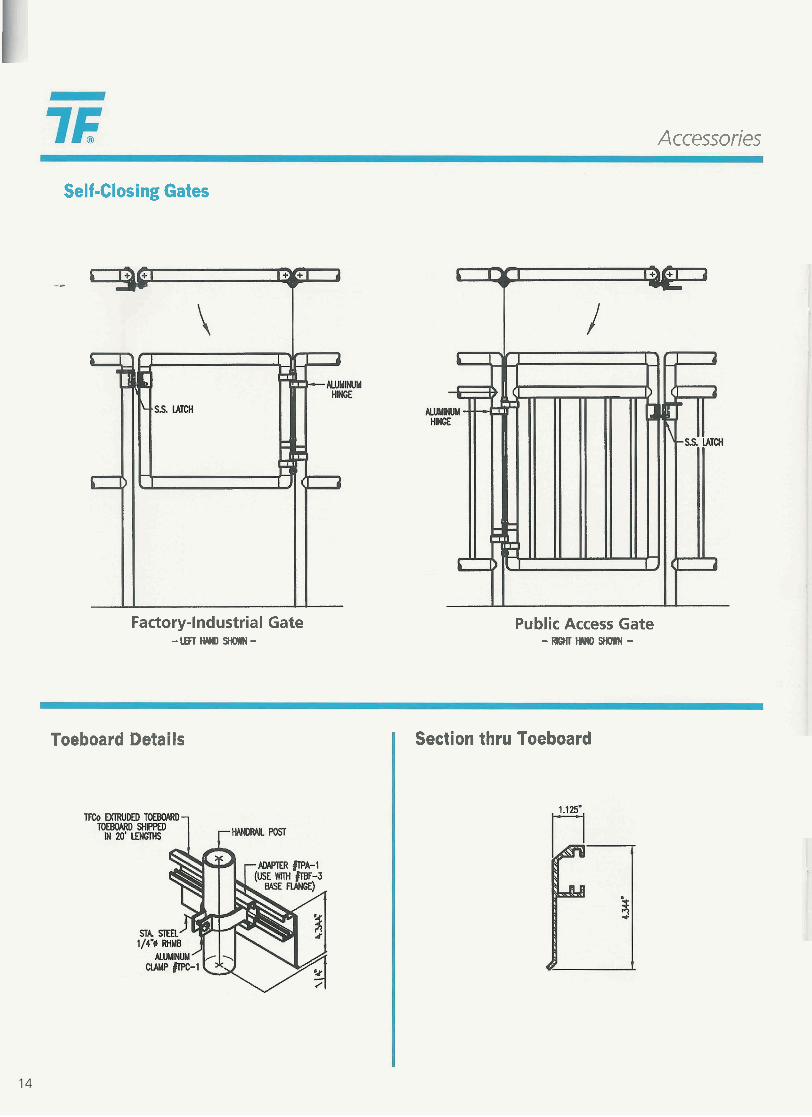
Accessories
Self-Closing Gates
- -
Factory-Industrial Gate - lEFlHI lDm-
Public Access Gate -RK;HIwm-
Toeboard Details I Section thru Toeboard
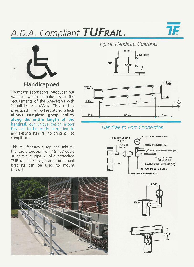
Typical Handicap Guardrail
Handicapped Thompson Fabricating introduces our handrail which complies with the requirements of the American's with 1
I 2'-6. Disabilities Act (ADA). This rail is I I l w I
produced in an offset style, which 1
allows complete grasp ability s ' M ~ . - . 30' YH. 3, ~1 I I 1 - - 1
along the entire length of the handrail. our unique design allows this rail to be easily retrofitted to Handrail to Post Connection any existing stair rail to bring it into compliance.
This rail features a top and mid-rail that are produced from 1 'X" schedule 40 aluminum pipe. All of our standard TUFRAIL base flanges and side mount brackets can be used to mount this rail.
1/4' ROUHD WD UME Samr (S.S.)
5/16' SOCI(EI EM
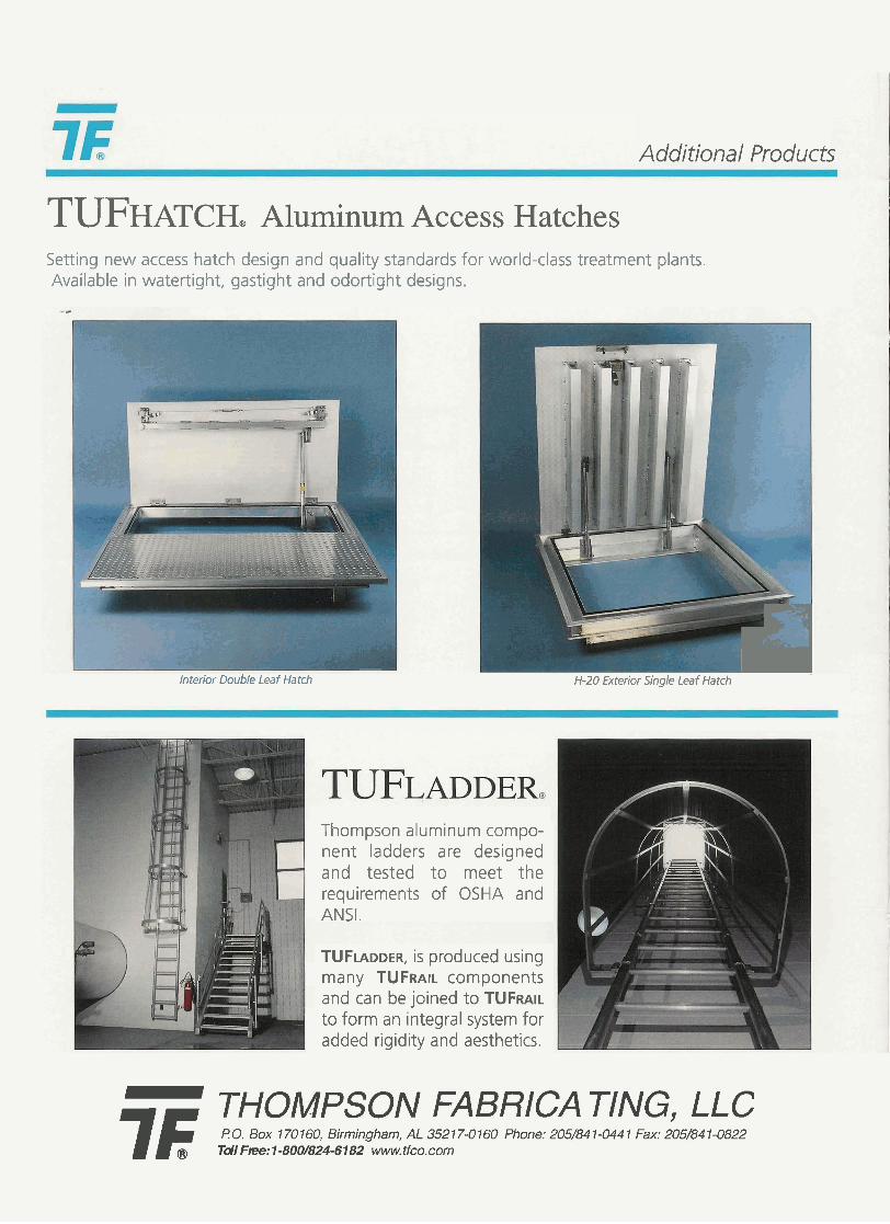
Additional Products
TUFHATCH, Aluminum Access Hatches Setting new access hatch design and quality standards for world-class treatment plants. Available in watertight, gastight and odortight designs.
- Interior Double Leaf Hatch I H-20 Exterior Single Leaf Hatch
Thompson aluminum compo- nent ladders are designed and tested to meet the requirements of OSHA and ANSI.
TUFLADDER, is produced using many TUFRAIL components and can be joined to TUFRAIL to form an integral system for added rigidity and aesthetics.
I
7F THOMPSON FABRICA TING, LLC P 0. Box 1 70 160, Birmingham, AL 352 17-0 160 Phone: 205/84 1-044 1 Fax: 205/84 1-0822 Tdl Ftee: 1 -800/824-6182 www. tfco.com