Embed Size (px)
Citation preview
L21: Induction machine control
L21: 7-MAY-2019
Lund University / LTH / IEA / AR / EIEN25 / 2019-05-07 2
Outlook
• Induction machine (IM) construction– Squirrel cage
– Rotor winding and slip-rings
• IM model & characteristics– Steinmetz equivalent circuit
– Vector representation and flux models
• Torque control– Feedback and observers
– Direct and deadbeat current control
Lund University / LTH / IEA / AR / EIEN25 / 2019-05-07 3
AC machines
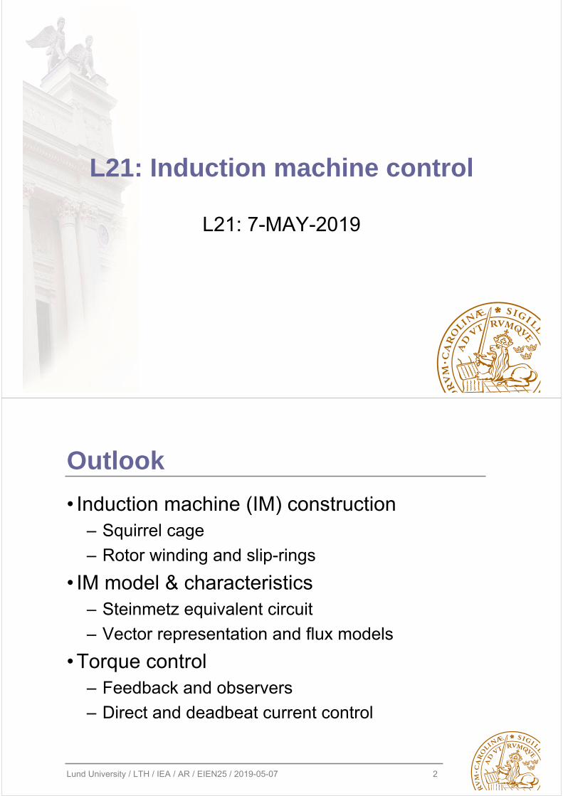
• Synchronous machines– Rotor field is created by
excitation – permanent magnets or/and externally supplied currents
• Asynchronous machines– Rotor field is created by
induction – rotor current is supplied by transformer action
Stator electrical frequency, f [1/s] [Hz]
Number of pole pairs, pp=p/2
Rotor synchronous speed, ns=f/pp*60 [1/min] [rpm]
Rotor asynchronous speed, nr=ns*(1-slip) [1/min] [rpm]
is
ir
ψsσ
ψrσ
ψm stator
rotor
Lund University / LTH / IEA / AR / EIEN25 / 2019-05-07 4
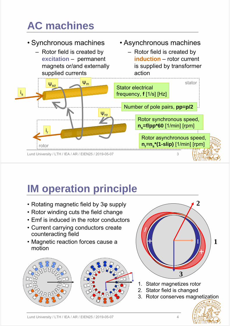
IM operation principle• Rotating magnetic field by 3φ supply• Rotor winding cuts the field change• Emf is induced in the rotor conductors• Current carrying conductors create
counteracting field• Magnetic reaction forces cause a
motion1
2
31. Stator magnetizes rotor2. Stator field is changed3. Rotor conserves magnetization
Lund University / LTH / IEA / AR / EIEN25 / 2019-05-07 5
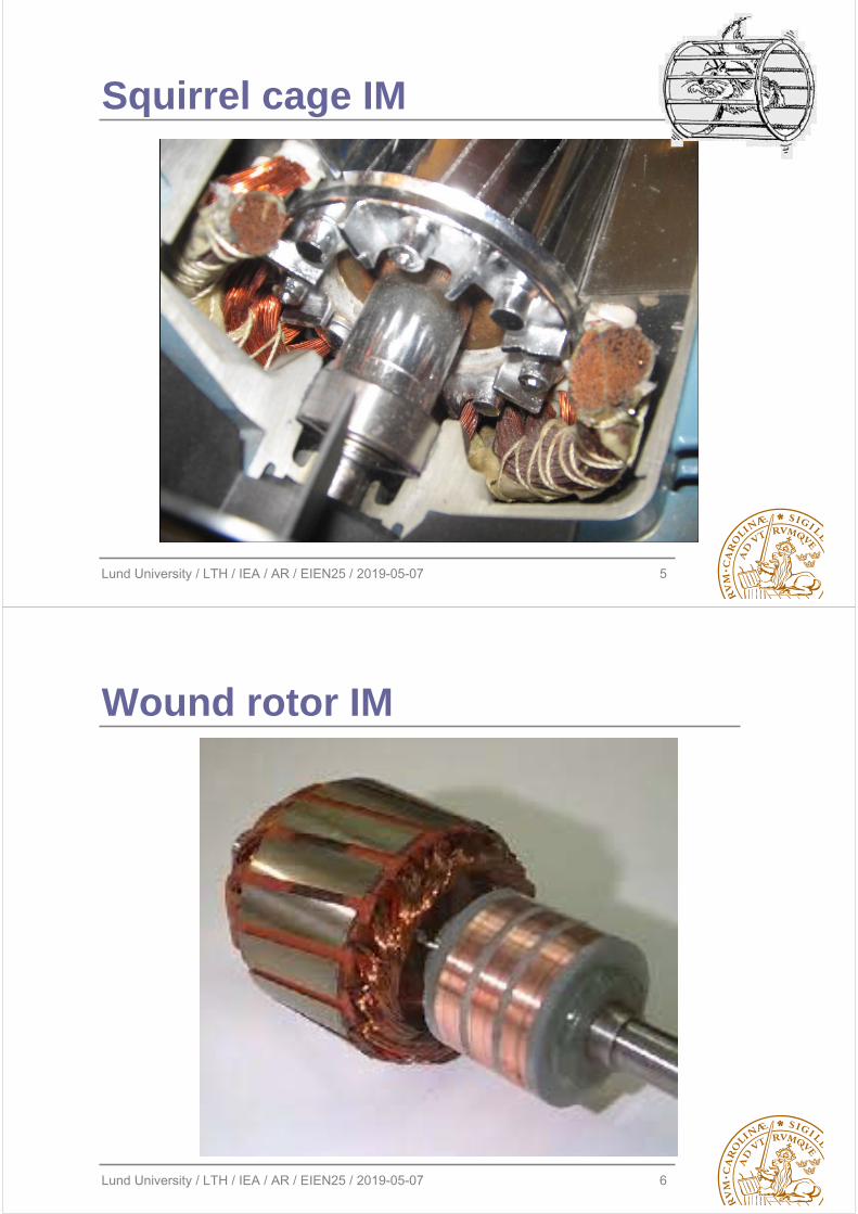
Squirrel cage IM
Lund University / LTH / IEA / AR / EIEN25 / 2019-05-07 6
Wound rotor IM
Lund University / LTH / IEA / AR / EIEN25 / 2019-05-07 7
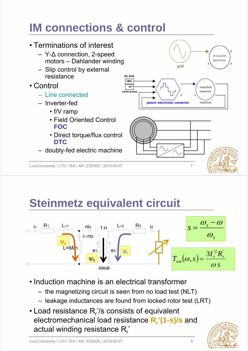
IM connections & control
• Terminations of interest– Y-Δ connection, 2-speed
motors – Dahlander winding– Slip control by external
resistance
• Control– Line connected– Inverter-fed
• f/V ramp• Field Oriented Control
FOC• Direct torque/flux control
DTC– doubly-fed electric machine
power electronic converter
induction
machine
machine
Udc
dc-link
is*
reference
Lund University / LTH / IEA / AR / EIEN25 / 2019-05-07 8
Steinmetz equivalent circuit
• Induction machine is an electrical transformer– the magnetizing circuit is seen from no load test (NLT)
– leakage inductances are found from locked rotor test (LRT)
• Load resistance Rr’/s consists of equivalent electromechanical load resistance Rr’(1-s)/s and actual winding resistance Rr’
s
RIsT rr
em
'2'3, ψδ
ψr
ψs
s
ss
Lund University / LTH / IEA / AR / EIEN25 / 2019-05-07 9
-1500 -1000 -500 0 500 1000 1500 2000 2500 3000-50
-40
-30
-20
-10
0
10
20
30
40
50
torq
ue,
T [
Nm
]
speed, n [rpm]
2 1.5 1 0.5 0 -0.5 -1
-10
-8
-6
-4
-2
0
2
4
6
8
10
pow
er,
P [
kW]
slip, s [-]
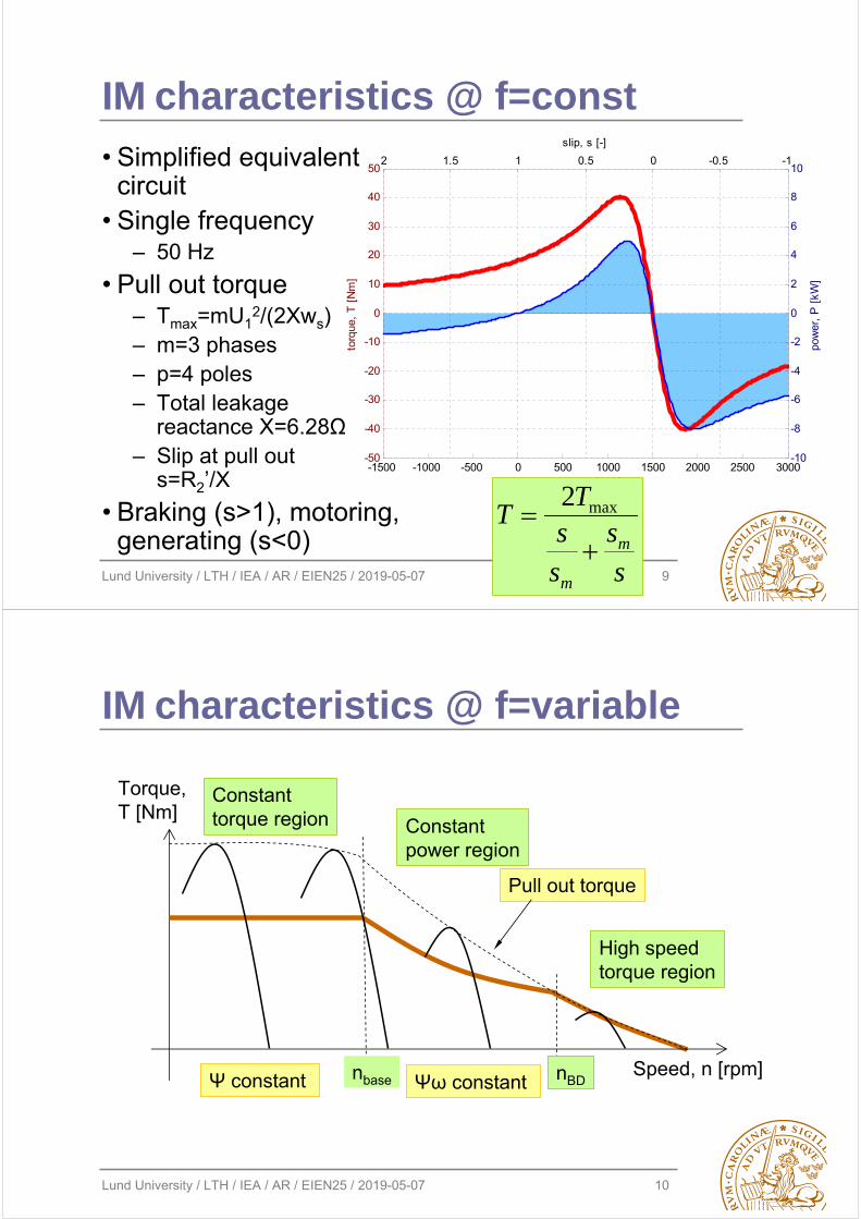
IM characteristics @ f=const
• Simplified equivalent circuit
• Single frequency– 50 Hz
• Pull out torque – Tmax=mU1
2/(2Xws)– m=3 phases– p=4 poles– Total leakage
reactance X=6.28Ω– Slip at pull out
s=R2’/X
• Braking (s>1), motoring, generating (s<0)
ss
ss
TT
m
m
max2
Lund University / LTH / IEA / AR / EIEN25 / 2019-05-07 10
IM characteristics @ f=variable
Speed, n [rpm]
Torque, T [Nm]
Pull out torque
nbase nBD
High speedtorque region
Constant power region
Constant torque region
Ψ constant Ψω constant
Lund University / LTH / IEA / AR / EIEN25 / 2019-05-07 11
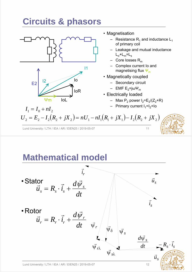
Circuits & phasors• Magnetisation
– Resistance R1 and inductance L1of primary coil
– Leakage and mutual inductance Lσ+Lm=Ls
– Core losses Rm
– Complex current Io and magnetising flux Ψm
• Magnetically coupled– Secondary circuit
– EMF E2=jωΨm
• Electrically loaded– Max P2 power I2=E2/(Z2+R)
– Primary current I1=I2+Io
Io
IoR
IoLΨm
E2I2
I1
201 nIII 222111122222 jXRIjXRnInUjXRIEU
Lund University / LTH / IEA / AR / EIEN25 / 2019-05-07 12
Mathematical model
• Stator
• Rotor
ri
si
r
r
s
s
su
su
dt
d s
ss iR
dt
diRu
dt
diRu
rrrr
ssss
Lund University / LTH / IEA / AR / EIEN25 / 2019-05-07 13
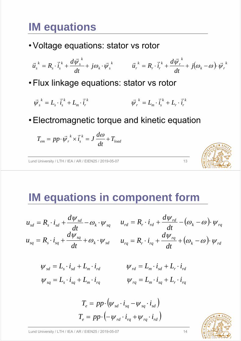
IM equations
ksk
ksk
ssk
s jdt
diRu
k
rk
krk
rrk
r jdt
diRu
krm
kss
ks iLiL
k
rrk
smk
r iLiL
loadk
sk
rem Tdt
dJippT
• Voltage equations: stator vs rotor
• Flux linkage equations: stator vs rotor
• Electromagnetic torque and kinetic equation
Lund University / LTH / IEA / AR / EIEN25 / 2019-05-07 14
IM equations in component form
sqksd
sdssd dt
diRu
sdksq
sqssq dt
diRu
rqkrd
rdrrd dt
diRu
rdkrq
rqrrq dt
diRu
sdsqsqsde iippT
rdmsdssd iLiL
rqmsqssq iLiL rdrsdmrd iLiL
rqrsqmrq iLiL
rdrqrqrde iippT
Lund University / LTH / IEA / AR / EIEN25 / 2019-05-07 15
2
wm
1
is
p/2
1
ur
Tld
wm
is
psis
us ir
Tm
pos
psir
p/2
Step
~=
Psiis
PsiTe
Psi ir
[0 -1 ; 1 0]* u
b
1/J
1s
1s
Lm/Lr
RrRs 1
s
1s
2
load
1
us
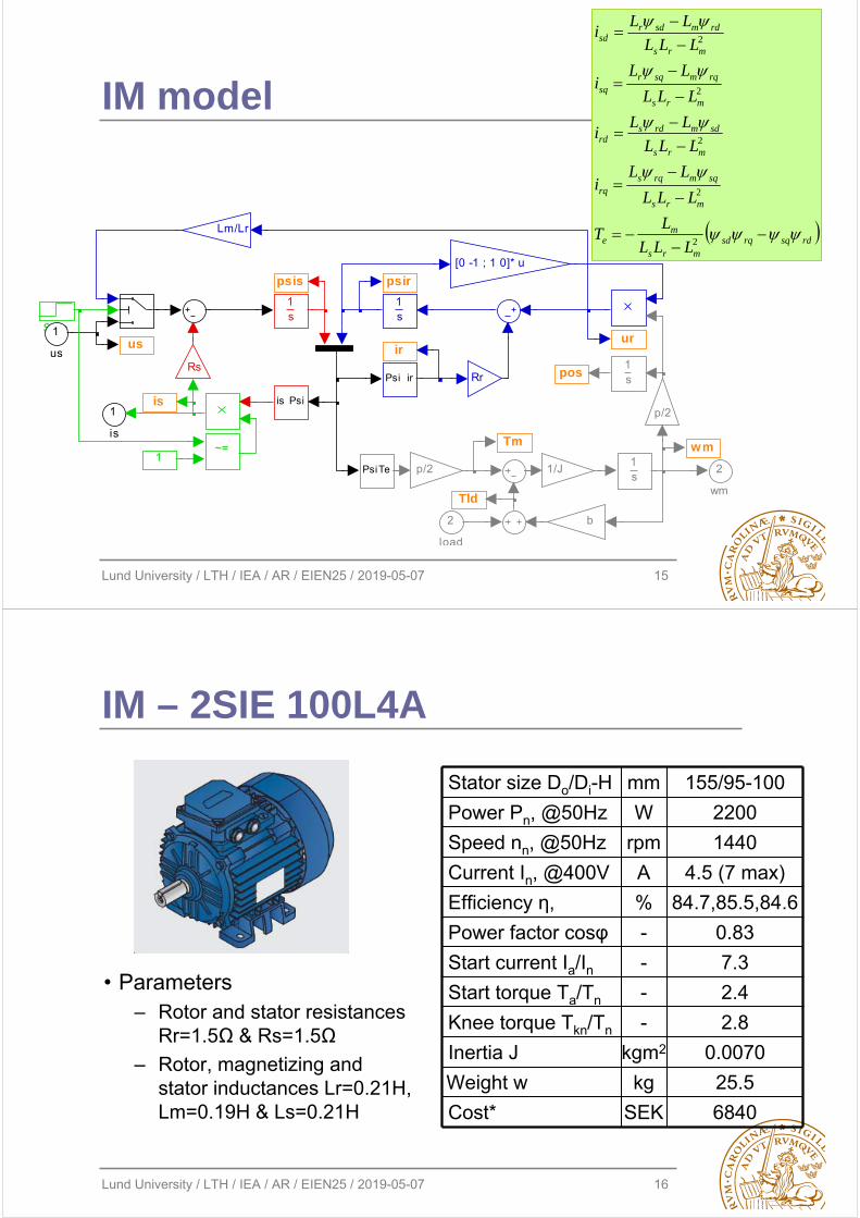
IM model
rdsqrqsdmrs
me
mrs
sqmrqsrq
mrs
sdmrdsrd
mrs
rqmsqrsq
mrs
rdmsdrsd
LLL
LT
LLL
LLi
LLL
LLi
LLL
LLi
LLL
LLi
2
2
2
2
2
Lund University / LTH / IEA / AR / EIEN25 / 2019-05-07 16
IM – 2SIE 100L4A
• Parameters– Rotor and stator resistances
Rr=1.5Ω & Rs=1.5Ω
– Rotor, magnetizing and stator inductances Lr=0.21H, Lm=0.19H & Ls=0.21H
0.0070kgm2Inertia J
2.8-Knee torque Tkn/Tn
7.3-Start current Ia/In2.4-Start torque Ta/Tn
1440rpmSpeed nn, @50Hz
4.5 (7 max)ACurrent In, @400V
84.7,85.5,84.6%Efficiency η,
Stator size Do/Di-H mm 155/95-100
Power Pn, @50Hz W 2200
Power factor cosφ - 0.83
Weight w kg 25.5
Cost* SEK 6840
Lund University / LTH / IEA / AR / EIEN25 / 2019-05-07 17
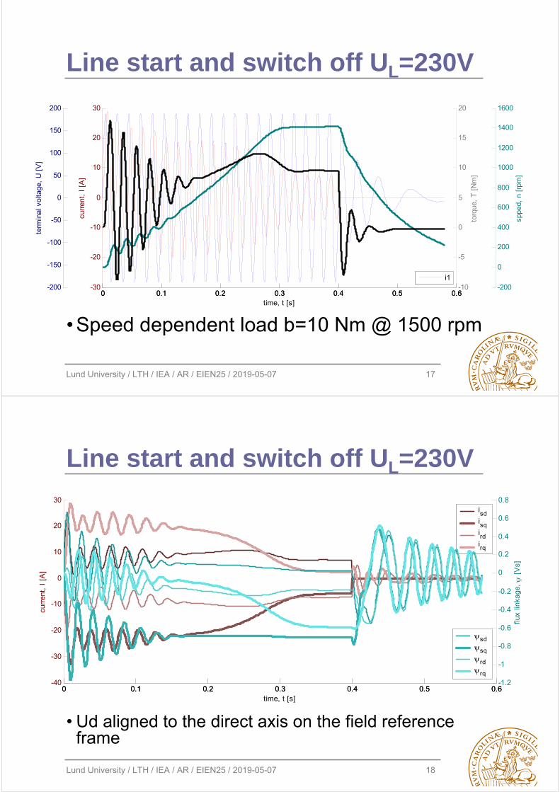
Line start and switch off UL=230V
• Speed dependent load b=10 Nm @ 1500 rpm
0 0.1 0.2 0.3 0.4 0.5 0.6-30
-20
-10
0
10
20
30
time, t [s]
curr
ent,
I [
A]
i1-200
0
200
400
600
800
1000
1200
1400
1600
sppe
d, n
[rp
m]
-200
-150
-100
-50
0
50
100
150
200
term
inal
vol
tage
, U
[V
]
0 0.1 0.2 0.3 0.4 0.5 0.6-10
-5
0
5
10
15
20
torq
ue,
T [
Nm
]
Lund University / LTH / IEA / AR / EIEN25 / 2019-05-07 18
Line start and switch off UL=230V
• Ud aligned to the direct axis on the field reference frame
0 0.1 0.2 0.3 0.4 0.5 0.6-40
-30
-20
-10
0
10
20
30
time, t [s]
curr
ent,
I [
A]
isdisqirdirq
0 0.1 0.2 0.3 0.4 0.5 0.6-1.2
-1
-0.8
-0.6
-0.4
-0.2
0
0.2
0.4
0.6
0.8
flux
linka
ge,
[V
s]
sdsqrdrq
Lund University / LTH / IEA / AR / EIEN25 / 2019-05-07 19
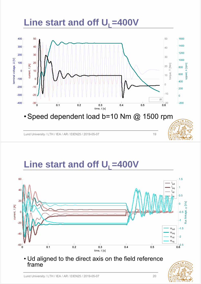
Line start and off UL=400V
• Speed dependent load b=10 Nm @ 1500 rpm
0 0.1 0.2 0.3 0.4 0.5 0.6-30
-20
-10
0
10
20
30
40
50
time, t [s]
curr
ent,
I [
A]
i1-200
0
200
400
600
800
1000
1200
1400
1600
sppe
d, n
[rp
m]
-400
-300
-200
-100
0
100
200
300
400
term
inal
vol
tage
, U
[V
]
0 0.1 0.2 0.3 0.4 0.5 0.6-20
-10
0
10
20
30
40
50
torq
ue,
T [
Nm
]
Lund University / LTH / IEA / AR / EIEN25 / 2019-05-07 20
Line start and off UL=400V
• Ud aligned to the direct axis on the field reference frame
0 0.1 0.2 0.3 0.4 0.5 0.6-60
-40
-20
0
20
40
60
time, t [s]
curr
ent,
I [
A]
isdisqirdirq
0 0.1 0.2 0.3 0.4 0.5 0.6-2.5
-2
-1.5
-1
-0.5
0
0.5
1
1.5
flux
linka
ge,
[V
s]
sdsqrdrq
Lund University / LTH / IEA / AR / EIEN25 / 2019-05-07 21
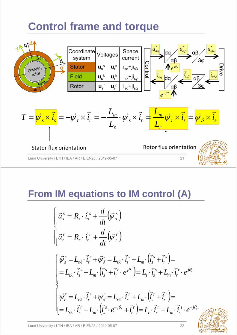
Control frame and torque
Rotor flux orientationStator flux orientation
ssrr
mrs
s
mrrss ii
L
Li
L
LiiT
α
β
stator
xy
ω s
field
(1±s)ωs
rotor
d
q
isd+jisqusr ur
rRotor
isx+jisyusk ur
kField
isα+jisβuss ur
sStator
Space current
VoltagesCoordinate
system Control
dq
αβ
αβ
3φ Drive
dq
αβ
αβ3φ
*dqu *
u
dqi
i
abci
*abcu
rje
rje
Lund University / LTH / IEA / AR / EIEN25 / 2019-05-07 22
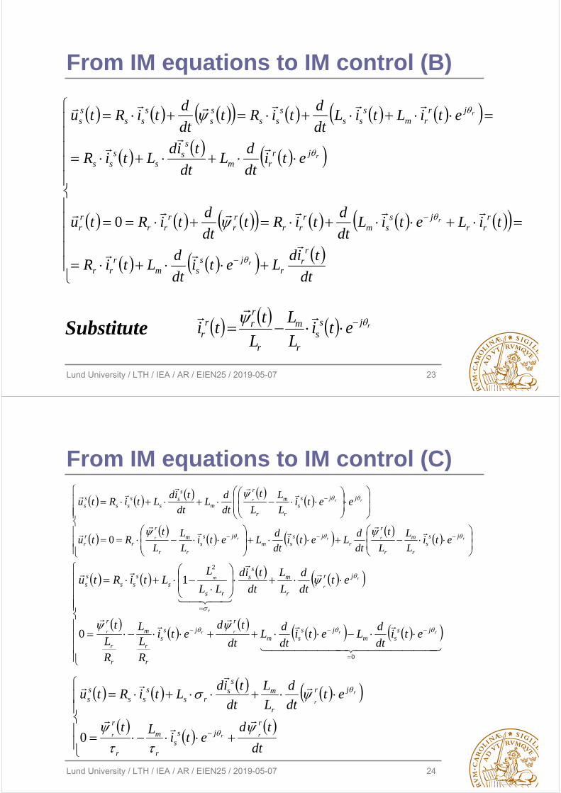
From IM equations to IM control (A)
rr
rrr
rr
ss
sss
ss
dt
diRu
dt
diRu
rr
rr
jssm
rrr
rr
jssm
rrr
rr
rsm
rrr
rrrr
rr
jrrm
sss
jrr
ssm
sss
sr
ssm
sss
ssss
ss
eiLiLieiLiL
iiLiLiL
eiLiLeiiLiL
iiLiLiL
Lund University / LTH / IEA / AR / EIEN25 / 2019-05-07 23
From IM equations to IM control (B)
dt
tidLeti
dt
dLtiR
tiLetiLdt
dtiRt
dt
dtiRtu
etidt
dL
dt
tidLtiR
etiLtiLdt
dtiRt
dt
dtiRtu
rr
rjs
smr
rr
rrr
jssm
rrr
rr
rrr
rr
jrrm
ss
ss
ss
jrrm
sss
sss
ss
sss
ss
r
r
r
r
0
rjss
r
m
r
rrr
r etiL
L
L
tti
Substitute
Lund University / LTH / IEA / AR / EIEN25 / 2019-05-07 24
From IM equations to IM control (C)
rrrrr
rrr
jss
r
m
r
r
rjs
smjs
sr
m
r
r
rrr
jjss
r
m
r
r
m
ss
ss
ssss
etiL
L
L
t
dt
dLeti
dt
dLeti
L
L
L
tRtu
eetiL
L
L
t
dt
dL
dt
tidLtiRtu
0
0
2
0
1
rrrrr
r
r
r
m
jssm
jssm
rjs
s
r
r
m
r
r
r
jr
r
ms
s
rss
sss
ss
etidt
dLeti
dt
dL
dt
tdeti
RLL
RL
t
etdt
d
L
L
dt
tid
LL
LLtiRtu
dt
tdeti
Lt
etdt
d
L
L
dt
tidLtiRtu
rjs
sr
m
r
r
jr
r
ms
srs
sss
ss
rrr
r
r
0
Lund University / LTH / IEA / AR / EIEN25 / 2019-05-07 25
tjdt
tdti
Lt
tL
LtiLj
dt
td
L
L
dt
tidLtiRtu
tejdt
tdeeti
Let
teL
LtieLj
dt
tde
L
L
dt
tideLetiRetu
etdt
deeti
Let
eetdt
d
L
Leti
dt
dLetiRetu
dqsl
dqdq
sr
m
r
dq
dq
r
mdqsrss
dq
r
mdq
srs
dqss
dqs
dqjsl
dqjjdq
sr
m
r
jdq
dqj
r
mdqs
jrss
dqj
r
mdq
sjrs
jdqss
jdqs
jdq
e
jjdqs
r
m
r
jdq
e
jjdq
r
mjdqsrs
jdqss
jdqs
r
rr
r
r
r
slrslsl
sl
r
r
ss
rssss
sl
r
slj
rs
sl
r
sj
rsl
r
sss
0
0
0
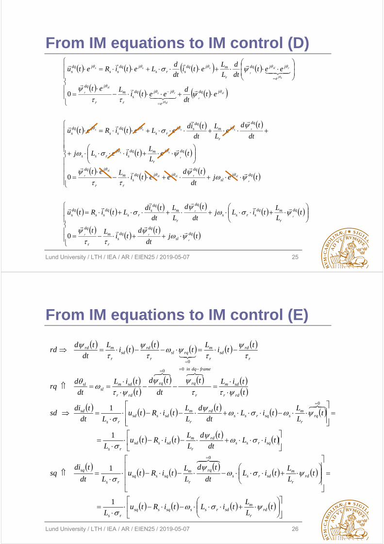
From IM equations to IM control (D)
Lund University / LTH / IEA / AR / EIEN25 / 2019-05-07 26
From IM equations to IM control (E)
tL
LtiLtiRtu
L
tL
LtiL
dt
td
L
LtiRtu
Ldt
tdisq
tiLdt
td
L
LtiRtu
L
tL
LtiL
dt
td
L
LtiRtu
Ldt
tdisd
t
tiLt
dt
td
t
tiL
dt
drq
tti
Lt
tti
L
dt
tdrd
rdr
msdrsssqssq
rs
rdr
msdrss
rq
r
msqssq
rs
sq
sqrssrd
r
msdssd
rs
rqr
mssqrss
rd
r
msdssd
rs
sd
rdr
sdm
r
framedqin
rqrq
rdr
sdmsl
sl
r
rdsd
r
mrqsl
r
rdsd
r
mrd
1
1
1
1
0
0
00
0
Lund University / LTH / IEA / AR / EIEN25 / 2019-05-07 27
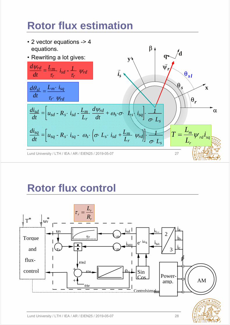
Rotor flux estimation• 2 vector equations -> 4
equations.
• Rewriting a lot gives:
rsi
r
s l
x
y
s
dq
drd
dt = Lm
r isd - 1
r rd
dsldt
= Lm isq
r rd disddt
= usd - Rs isd - LmLr
drd
dt + s Ls isq 1
Ls disq
dt = usq - Rs isq - s Ls isd + Lm
Lr rd 1
Lssqrd
r
m iL
LT
Lund University / LTH / IEA / AR / EIEN25 / 2019-05-07 28
Rotor flux control
r
Sin Cos Power-
amp.
2
3 r
+
+
Torque
and
flux-
control
i s
is
i sd
i sq
sl
r
s s
L m
L m
r
Controlsignal
AM
T * r*
e- js
i a
i b
i c
r
rr R
L
Lund University / LTH / IEA / AR / EIEN25 / 2019-05-07 29
si
r
sl
x
y
s
dq
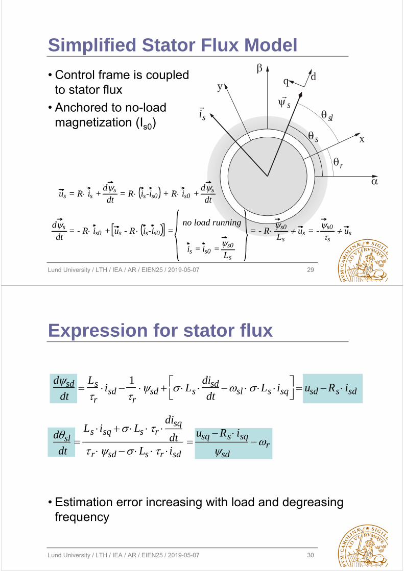
s
Simplified Stator Flux Model
us = R is + ds
dt = R is-is0 + R is0 +
ds
dt
ds
dt = - R is0 + us - R is-is0 =
no load running
is = is0 = s0
Ls
= - Rs0
Lsus = -
s0
sus
• Control frame is coupled to stator flux
• Anchored to no-load magnetization (Is0)
Lund University / LTH / IEA / AR / EIEN25 / 2019-05-07 30
Expression for stator flux
dsd
dt
Ls
risd
1
rsd Ls
disd
dtsl Ls isq
usd Rs isd
dsl
dt
Ls isq Ls r disq
dtr sd Ls r isd
usq Rs isq
sdr
• Estimation error increasing with load and degreasing frequency
Lund University / LTH / IEA / AR / EIEN25 / 2019-05-07 31
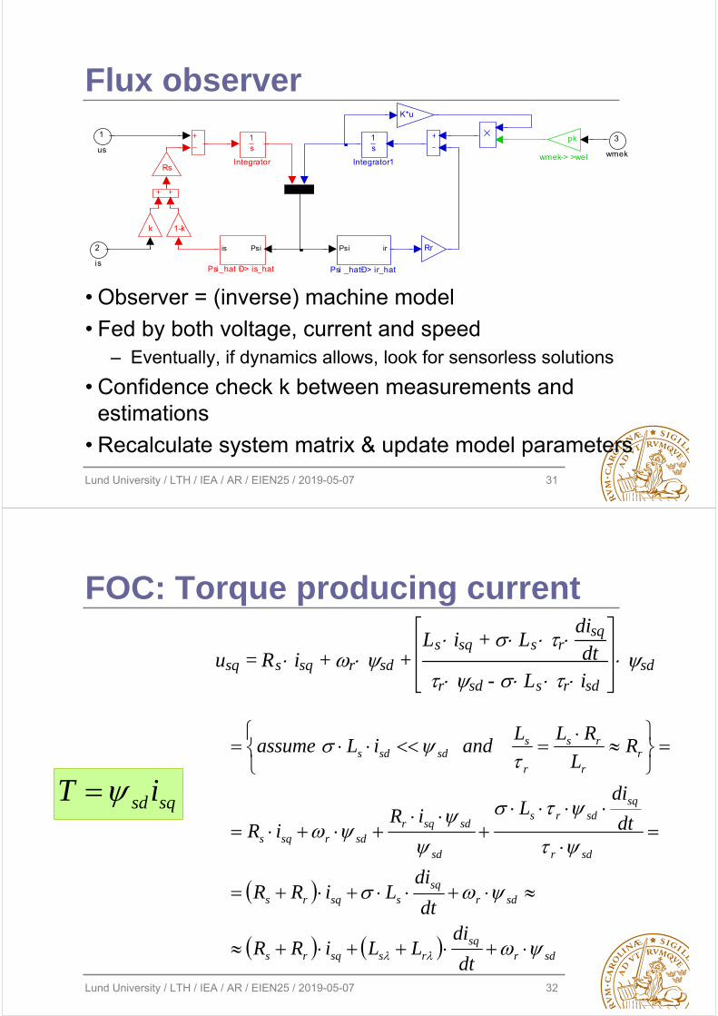
Flux observer
pk
wmek-> >wel
Psiis
Psi_hat Ð> is_hat
Psi ir
Psi _hatÐ> ir_hat
K*u
1s
Integrator1
1s
Integrator
1-kk
Rr
Rs
3
wmek
2
is
1
us
• Observer = (inverse) machine model
• Fed by both voltage, current and speed– Eventually, if dynamics allows, look for sensorless solutions
• Confidence check k between measurements and estimations
• Recalculate system matrix & update model parameters
Lund University / LTH / IEA / AR / EIEN25 / 2019-05-07 32
FOC: Torque producing current
usq = Rs isq + r sd + Ls isq + Ls r
disq
dtr sd - Ls r isd
sd
sdrsq
rssqrs
sdrsq
ssqrs
sdr
sqsdrs
sd
sdsqrsdrsqs
rr
rs
r
ssdsds
dt
diLLiRR
dt
diLiRR
dt
diLiR
iR
RL
RLLandiLassume
sqsd iT
Lund University / LTH / IEA / AR / EIEN25 / 2019-05-07 33
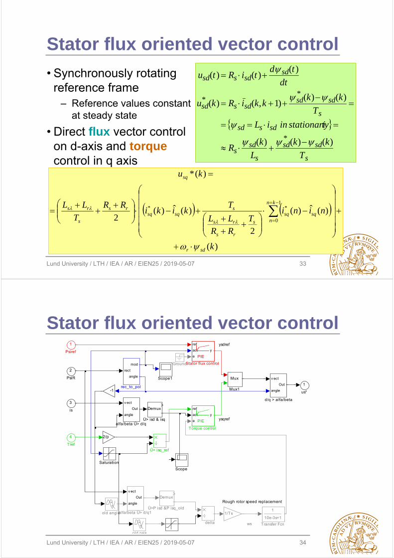
Stator flux oriented vector control
• Synchronously rotating reference frame
– Reference values constant at steady state
• Direct flux vector control on d-axis and torquecontrol in q axis
)(
)(ˆ)(
2
)(ˆ)(2
)(*
1
0
**
k
niniT
RRLL
Tkiki
RR
T
LL
ku
sdr
kn
nsqsq
s
rs
rs
ssqsq
rs
s
rs
sq
s
sdsd
s
sds
sdssd
s
sdsdsdssd
sdsdssd
T
kk
L
kR
tystationariiniL
T
kkkkiRku
dt
tdtiRtu
)()()(
)()()1,()(
)()()(
*
**
Lund University / LTH / IEA / AR / EIEN25 / 2019-05-07 34
Stator flux oriented vector control
ysqref
ysdref
Rough rotor speed replacement
ws
1
us*
Demux
Ü>P isd &P isq_old
Ü> isq_ref
Demux
Ü> isd & isq
delta
rect
mod
angle
rec_to_pol
old psis
old angle
v ect
angle
Out
alfa/beta Ü> d/q1
v ect
angle
Out
alfa/beta Ü> d/q
1
10e-3s+1
Transfer Fcn
ref
act
e
y
PIE
Torque control
ref
act
e
y
PIE
Stator flux control
Scope1
Scope
Saturation
Mux
Mux1
Ground
1/Ts
2/p
-1
v ect
angle
Out
d/q > alfa/beta
4
Tref
3
is
2
PsiR
1
Psiref
Lund University / LTH / IEA / AR / EIEN25 / 2019-05-07 35
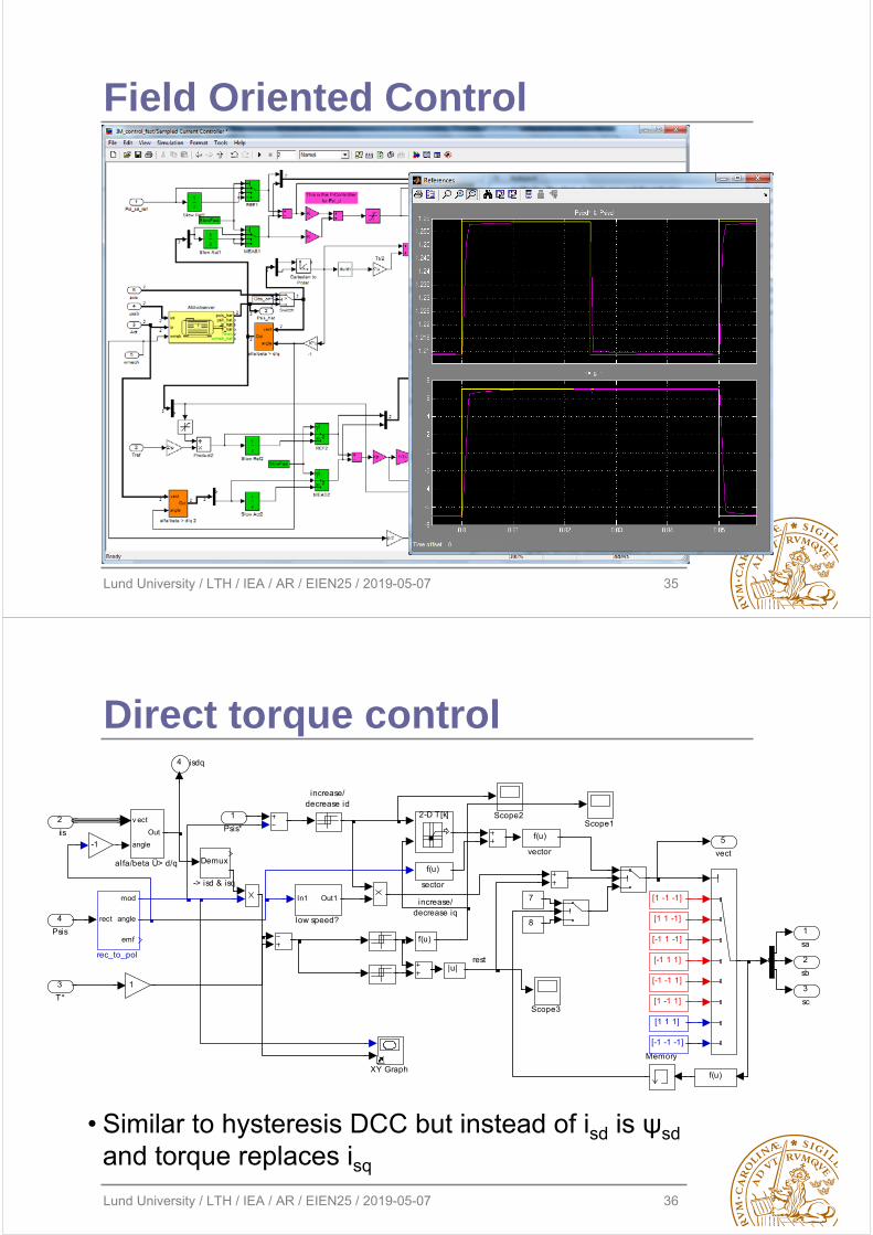
Field Oriented Control
Lund University / LTH / IEA / AR / EIEN25 / 2019-05-07 36
increase/decrease iq
rest
is5
vect
4 isdq
3
sc
2
sb
1
sa
f(u)
f(u)
vector
f(u)
f(u)
sector
rect
mod
angle
emf
rec_to_pol
In1 Out1
low speed?
increase/decrease id
v ect
angle
Out
alfa/beta Ü> d/q
XY Graph
Scope3
Scope2Scope1
Memory
1
-1
2-D T[k]
em
[1 1 1]
[-1 -1 -1]
[1 -1 -1]
[1 1 -1]
[1 -1 1]
[-1 -1 1]
[-1 1 1]
7
8
[-1 1 -1]
|u|
Demux
-> isd & isq
4
Psis
3
T*
2
i
1
Psis*
Direct torque control
• Similar to hysteresis DCC but instead of isd is ψsd
and torque replaces isq
Lund University / LTH / IEA / AR / EIEN25 / 2019-05-07 37
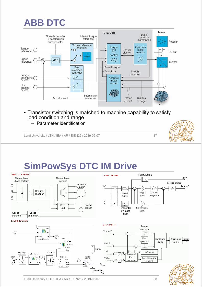
ABB DTC
• Transistor switching is matched to machine capability to satisfyload condition and range
– Parameter identification
Lund University / LTH / IEA / AR / EIEN25 / 2019-05-07 38
SimPowSys DTC IM Drive
Lund University / LTH / IEA / AR / EIEN25 / 2019-05-07 39
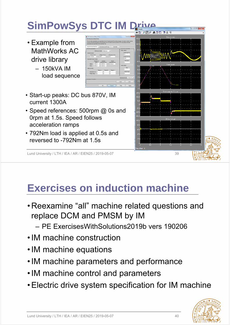
SimPowSys DTC IM Drive
• Example from MathWorks AC drive library
– 150kVA IM load sequence
• Start-up peaks: DC bus 870V, IM current 1300A
• Speed references: 500rpm @ 0s and 0rpm at 1.5s. Speed follows acceleration ramps
• 792Nm load is applied at 0.5s and reversed to -792Nm at 1.5s
Lund University / LTH / IEA / AR / EIEN25 / 2019-05-07 40
Exercises on induction machine
• Reexamine “all” machine related questions and replace DCM and PMSM by IM
– PE ExercisesWithSolutions2019b vers 190206
• IM machine construction
• IM machine equations
• IM machine parameters and performance
• IM machine control and parameters
• Electric drive system specification for IM machine