Embed Size (px)
Citation preview
LAB 10:Encoding and Decoding Touch-Tone Signals
EE224 section C JINGXUAN SUN
4/15/2013
Introduction: In this lab, we will introduce a practical application where
sinusoidal signals are used to transmit information: a touch-one dialer. then, we
will design and implement a bandpass FIR filer in matlab in order to do the
decoding automatically.
3.1 DTMF Dial Function
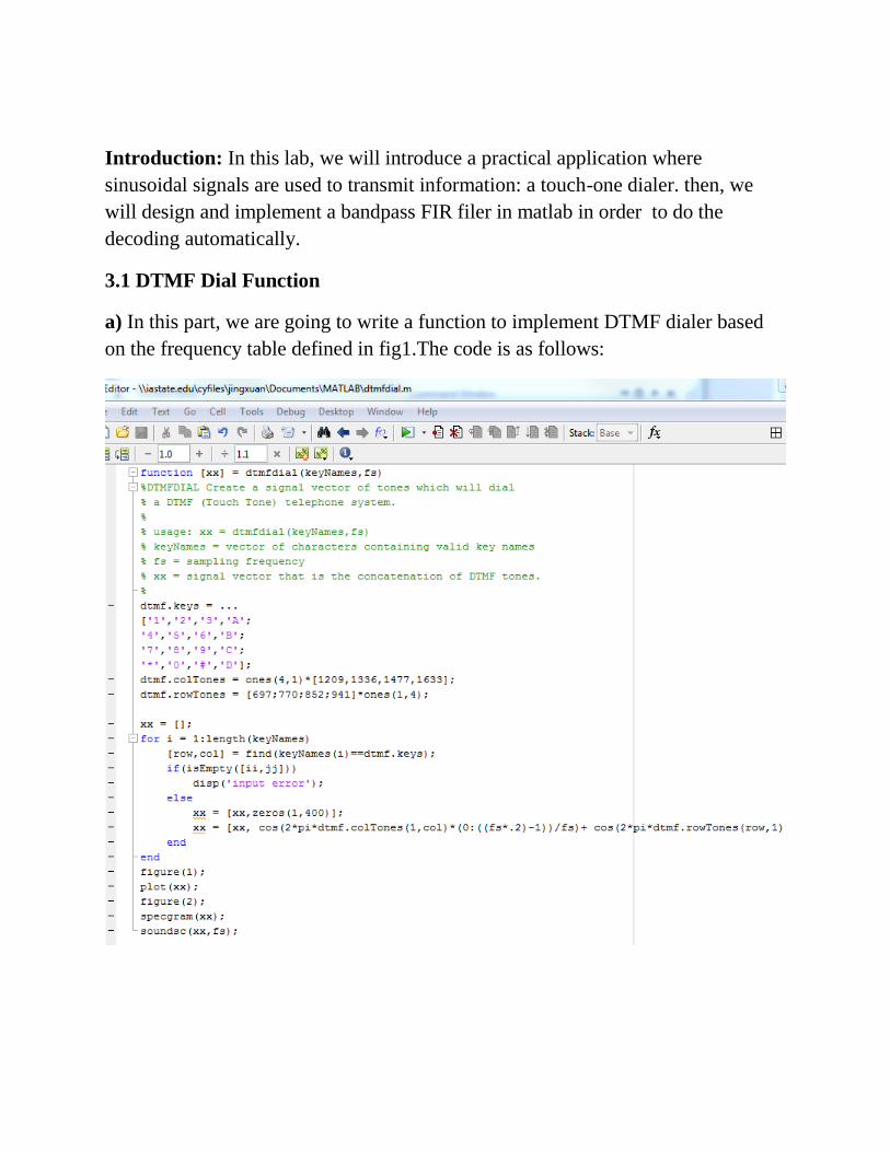
a) In this part, we are going to write a function to implement DTMF dialer based
on the frequency table defined in fig1.The code is as follows:
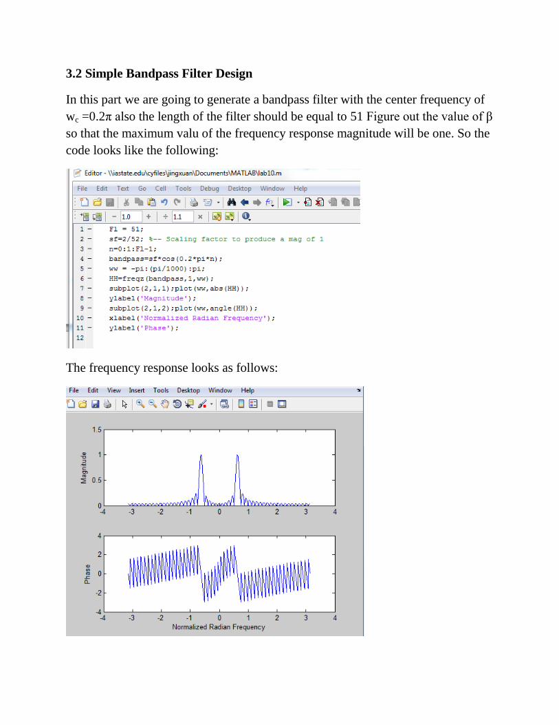
3.2 Simple Bandpass Filter Design
In this part we are going to generate a bandpass filter with the center frequency of
wc =0.2π also the length of the filter should be equal to 51 Figure out the value of β
so that the maximum valu of the frequency response magnitude will be one. So the
code looks like the following:
The frequency response looks as follows:
Then, we can find out that the region which got passed on y axis is larger than
0.707, then, we use the matlab function to locate the frequency, the code looks as
follows:
And the result BOM = 0.068π.
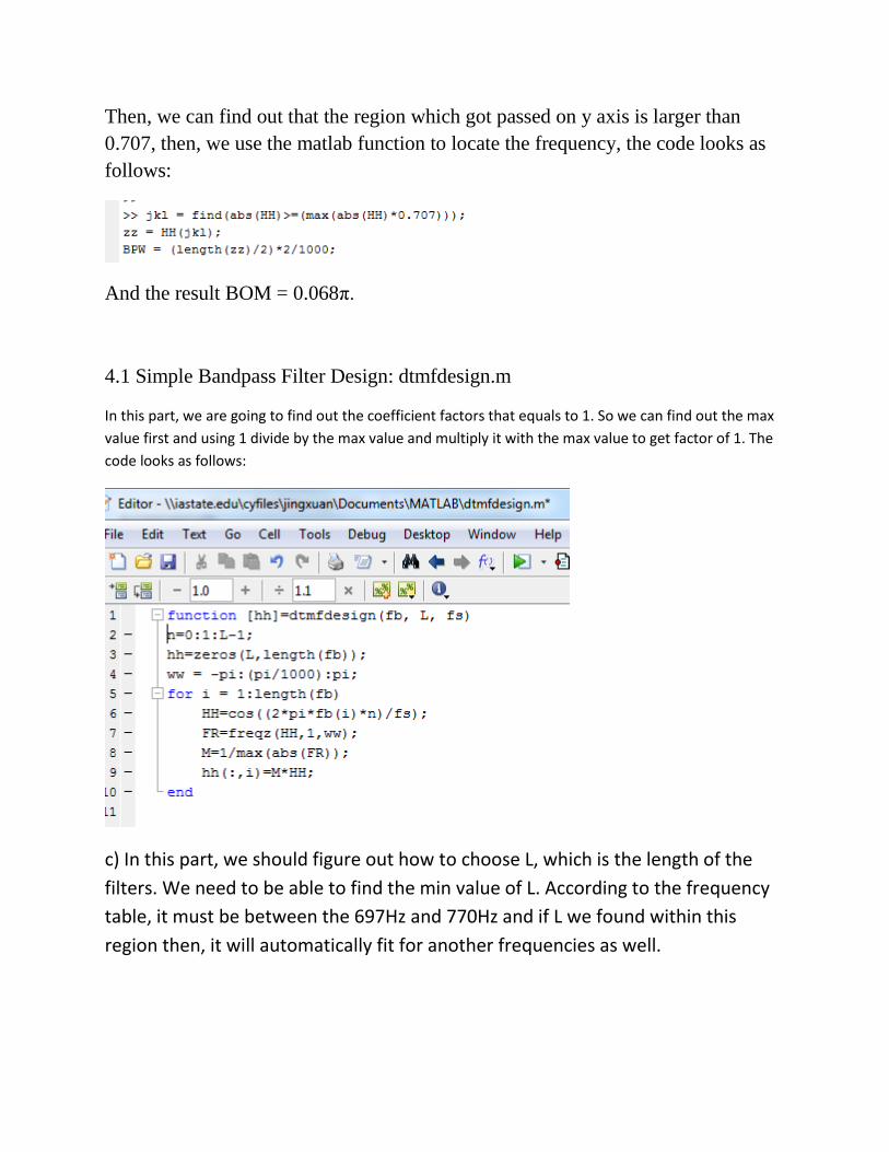
4.1 Simple Bandpass Filter Design: dtmfdesign.m
In this part, we are going to find out the coefficient factors that equals to 1. So we can find out the max
value first and using 1 divide by the max value and multiply it with the max value to get factor of 1. The
code looks as follows:
c) In this part, we should figure out how to choose L, which is the length of the
filters. We need to be able to find the min value of L. According to the frequency
table, it must be between the 697Hz and 770Hz and if L we found within this
region then, it will automatically fit for another frequencies as well.
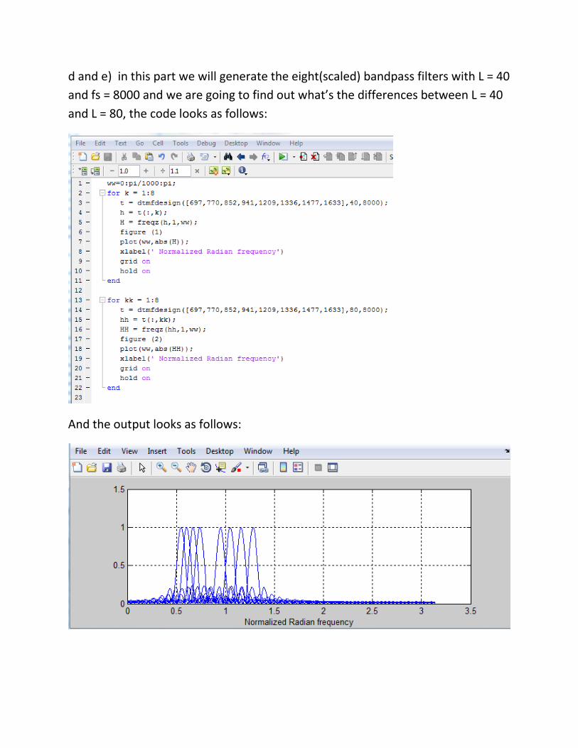
d and e) in this part we will generate the eight(scaled) bandpass filters with L = 40
and fs = 8000 and we are going to find out what’s the differences between L = 40
and L = 80, the code looks as follows:
And the output looks as follows:
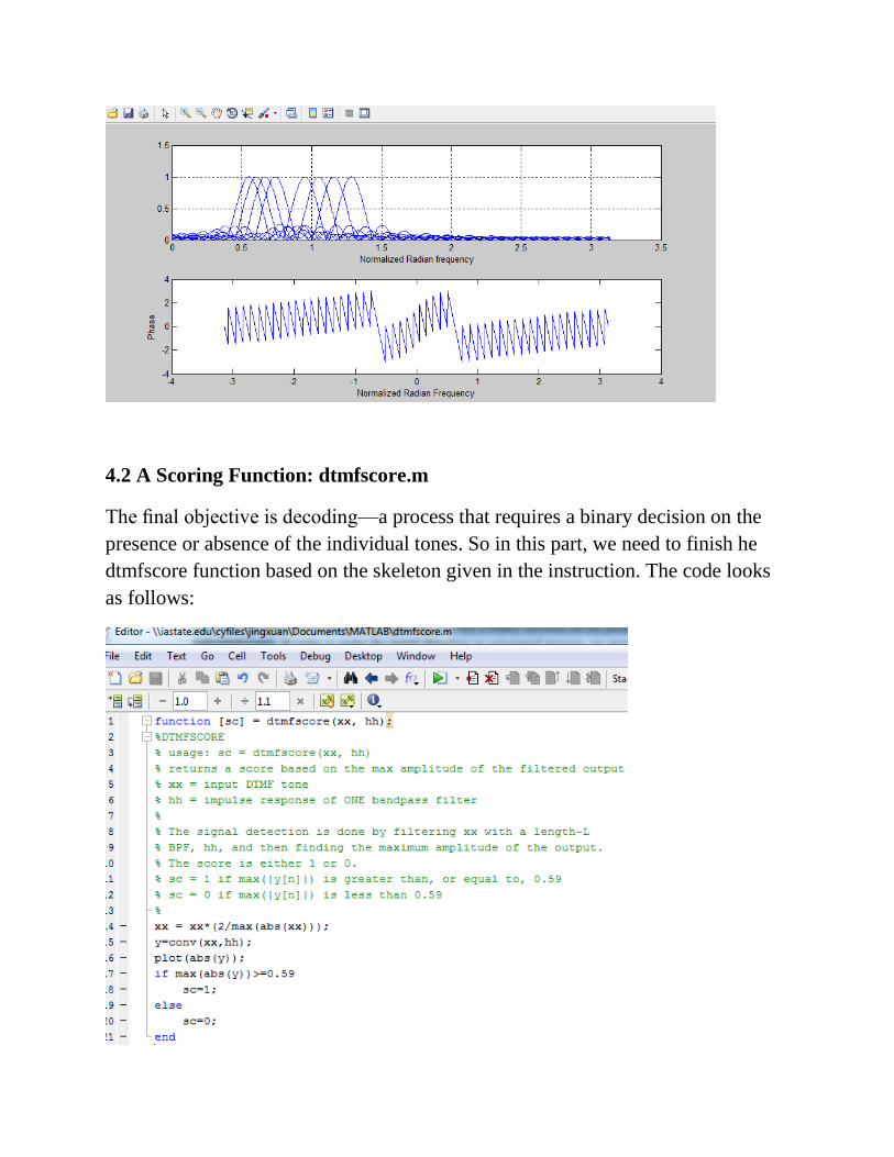
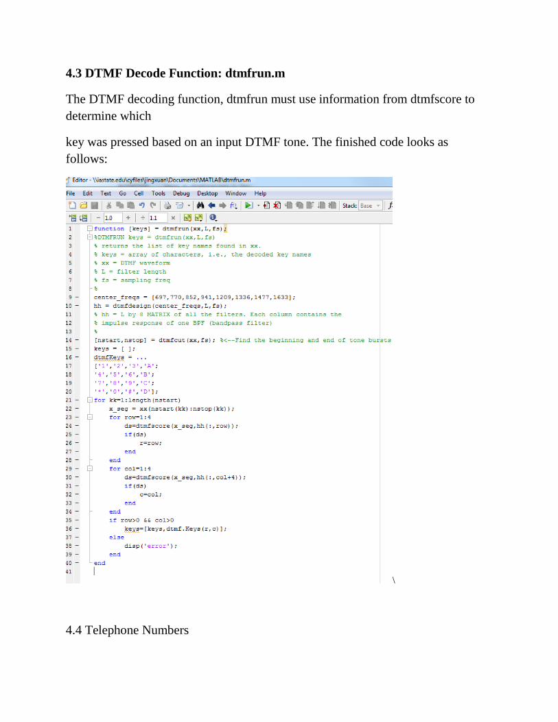
4.2 A Scoring Function: dtmfscore.m
The final objective is decoding—a process that requires a binary decision on the
presence or absence of the individual tones. So in this part, we need to finish he
dtmfscore function based on the skeleton given in the instruction. The code looks
as follows:
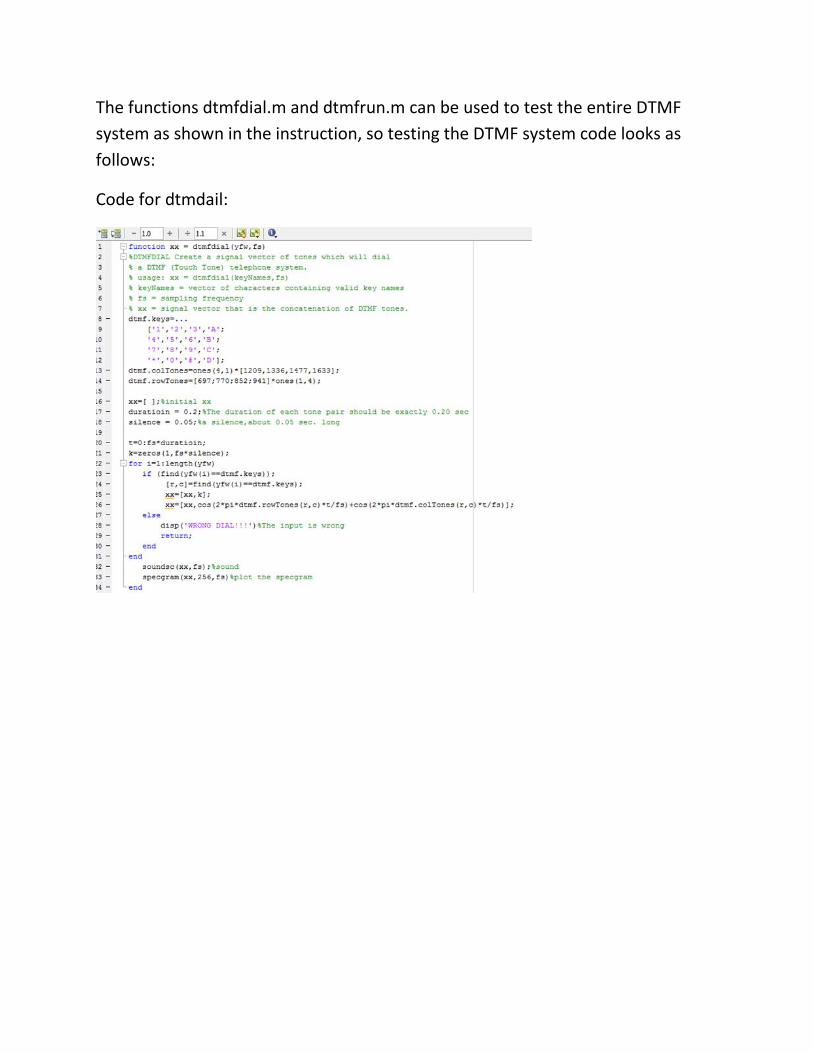
4.3 DTMF Decode Function: dtmfrun.m
The DTMF decoding function, dtmfrun must use information from dtmfscore to
determine which
key was pressed based on an input DTMF tone. The finished code looks as
follows:
\
4.4 Telephone Numbers
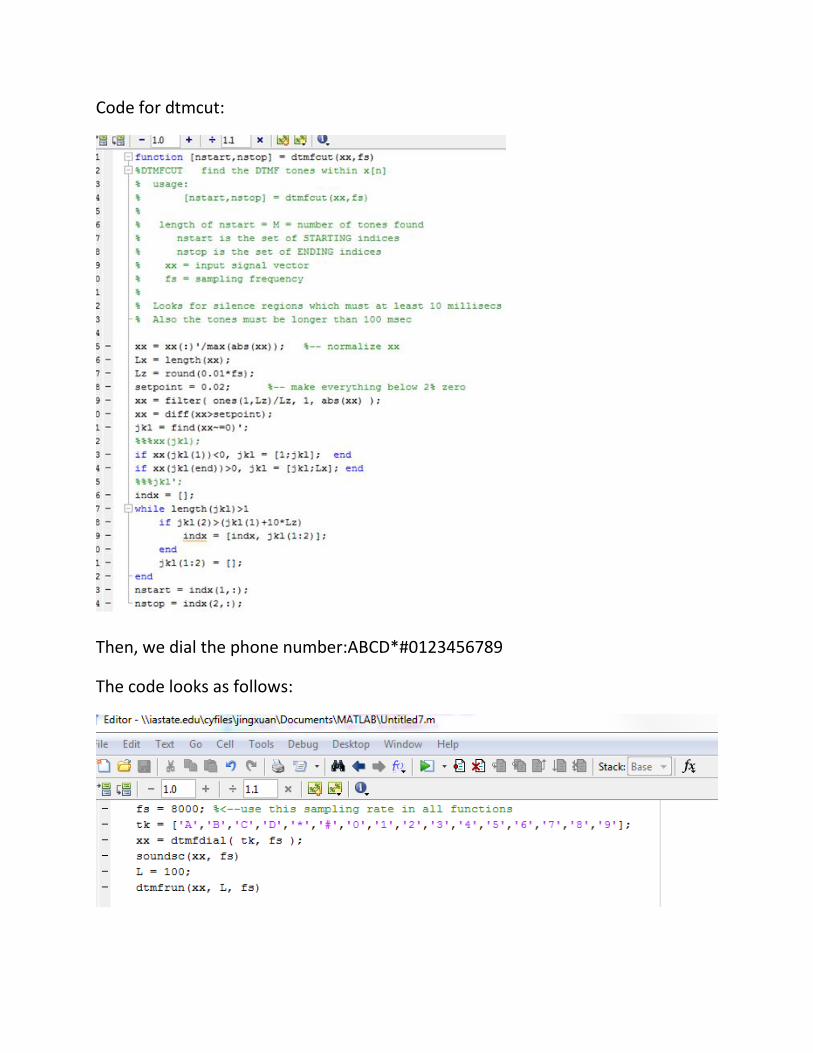
The functions dtmfdial.m and dtmfrun.m can be used to test the entire DTMF
system as shown in the instruction, so testing the DTMF system code looks as
follows:
Code for dtmdail:
Code for dtmcut:
Then, we dial the phone number:ABCD*#0123456789
The code looks as follows:
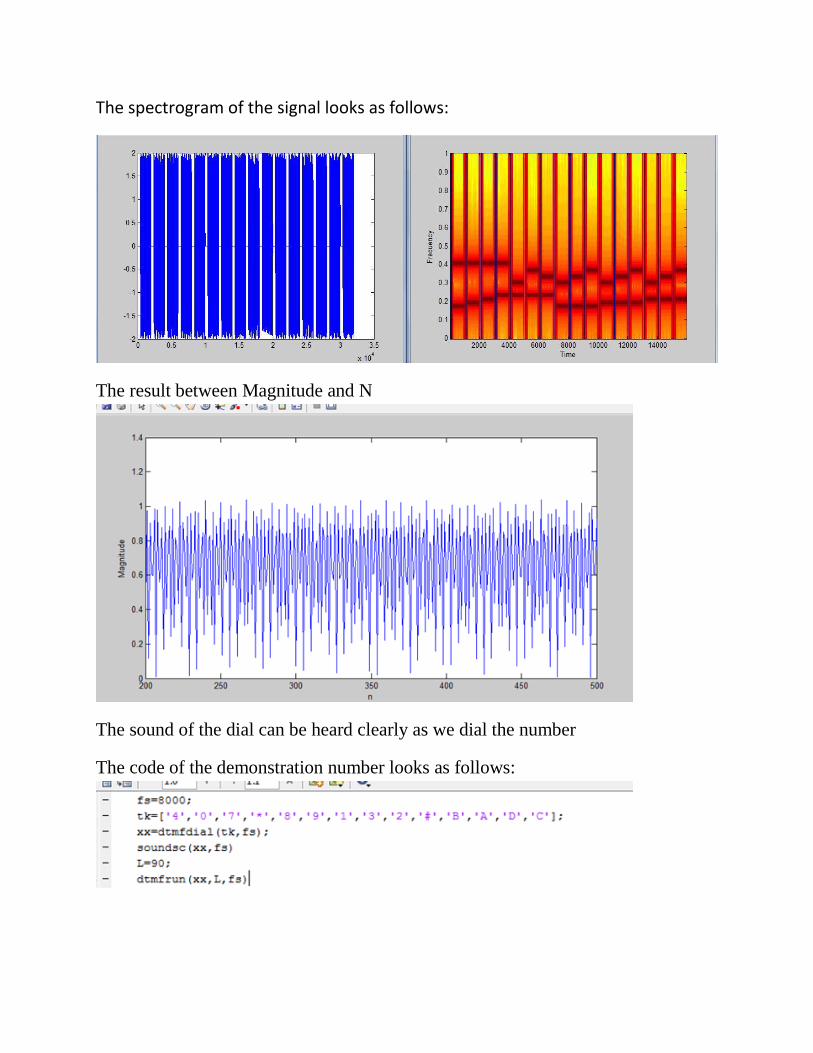
The spectrogram of the signal looks as follows:
The result between Magnitude and N
The sound of the dial can be heard clearly as we dial the number
The code of the demonstration number looks as follows:
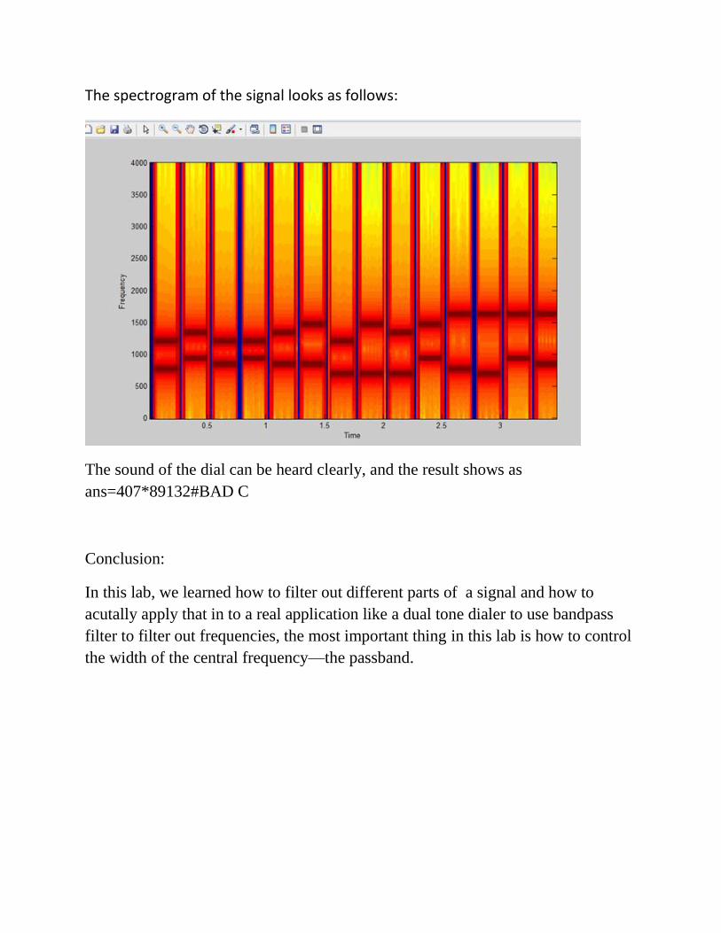
The spectrogram of the signal looks as follows:
The sound of the dial can be heard clearly, and the result shows as
ans=407*89132#BAD C
Conclusion:
In this lab, we learned how to filter out different parts of a signal and how to
acutally apply that in to a real application like a dual tone dialer to use bandpass
filter to filter out frequencies, the most important thing in this lab is how to control
the width of the central frequency—the passband.