Embed Size (px)
Citation preview
COLORADO SCHOOL OF MINES
LABORATORY EVALUATION OF PROPPANT TRANSPORT IN
COMPLEX FRACTURE SYSTEMS
Master of Science Petroleum Engineering Thesis Proposal
for
Rakshit Sahai
09/20/2011
The attached document is a Master of Science thesis proposal for Rakshit Sahai. It contains a detailed
outline of the proposed thesis work, objectives for the project and a summary of the completed
coursework. Your permission and agreement with the project as outlined in this document is requested.
Date: Submitted by: .
Rakshit Sahai
Date: Approved by: .
Advisor, Dr. Jennifer Miskimins
Date: Approved by: .
Committee Member, Dr. Ramona Graves
Date: Approved by: .
Committee Member, Dr. William Fleckenstein
2
Table of Contents
1 Introduction ............................................................................................................................................... 3
2 Literature Review ...................................................................................................................................... 5
2.1 Hydraulic Fracturing in a Naturally Fractured Reservoir ................................................................. 6
2.2 Slickwater Fracturing Technology...................................................................................................... 7
2.3 Proppant Transport ........................................................................................................................... 8
3 Objectives ............................................................................................................................................... 11
4 Methodology ............................................................................................................................................ 12
4.1 Experimental Parameters and Test Cases ........................................................................................ 12
4.2 Experimental Set Up ........................................................................................................................ 14
4.2.1 Slickwater Slurry ........................................................................................................................ 14
4.2.2 Testing System ............................................................................................................................ 14
4.2.3 Slot Configurations .................................................................................................................... 16
5 Project Timeline and Coursework ........................................................................................................... 18
6 References ............................................................................................................................................... 19
7 Research Sponsor .................................................................................................................................... 20
3
1 Introduction
Natural gas production from shale gas reservoirs has shown a rapidly growing trend over the past
decade and has become a significant source of U.S. domestic gas supply. In the U.S. alone, the
production from shale gas reservoirs has rapidly increased from 0.39 Tcf in 2000 to 4.87 Tcf in
2010 and contributed to 23 percent of the U.S. natural gas production in 2010 (US Energy
Information Administration, 2011). The use of hydraulic fracturing in conjunction with
horizontal drilling has been the “game-changer” in the petroleum industry over the past decade
and has contributed to economical natural gas production from low permeability shale reservoirs.
With the U.S. Energy Information Administration’s (EIA) energy projections anticipating shale
gas production to approximately double by 2035 and play a dominant role in meeting US energy
demands, it is expected that hydraulic fracturing will continue to play a major role in enhancing
recoverable natural gas reserves and daily production from these low permeability shale
formations.
Since the inception of hydraulic fracturing in 1947, fracturing technology has improved
significantly over the decades. With a global paradigm shift towards exploring unconventional
resources (especially shale reservoirs) over the last two decades, the industry focus has shifted
towards hydraulic fracturing and nearly all unconventional wells are fractured for production to
be economically viable. For shale gas development, compared to conventional gelled fluid
fracturing, slickwater fracturing has become the preferred choice for stimulation. The main
driving factors for change in this mindset include:
a) Need for cost cutting as the price of natural gas declined. Slickwater fracture treatments
are relatively cheap and easy to perform;
b) Low in situ permeability of shale gas reservoirs such that the reservoirs aren’t able to
effectively clean-up the gel. In comparison, slickwater fracturing causes little to no gel
damage to the proppant pack; and,
c) Potential of low viscosity slickwater fluids to generate longer fracture half-lengths
(without excessive height growth) and thus increasing the stimulated reservoir volume.
The complexity of the fracture systems in shale gas reservoirs directly affects production and
reserve recovery; whereas at the same time, conductivity of those fractures facilitates those rates
4
and recoveries. Little is understood about how well the proppant is transported in these complex
systems. Much speculation exists in the industry as to how well the proppant “turns the corner”
or, in other words, how efficiently the proppant is transported from the main fracture into
subsidiary fractures, if it is at all. During the hydraulic fracturing of shale reservoirs, it has been
observed that 100 mesh sand works well in some reservoirs but not in all. It is speculated that the
presence of natural fractures in shale reservoirs contributes to such behavior and complicates the
proppant transport in complex fracture networks.
The process of proppant transport in single vertical fractures has been previously studied using
various slot flow model experiments (Kern et al., 1959, Medlin et al., 1985, and Woodworth and
Miskimins, 2007). Prediction of proppant transport in complex fracture networks is important
and would be useful for both designing fracture treatments and for post-treatment analysis. The
purpose of this research is to evaluate proppant transport in complex fracture systems in a low
pressure laboratory setting by creating a series of complex slot configurations and flowing
slickwater slurries through them.
5
2 Literature Review
Starting in 1947, hydraulic fracturing has developed into one of the main well stimulation
techniques for improving the productivity of oil and gas wells globally. With the recent shift in
focus of the petroleum industry towards tight unconventional reservoirs, hydraulic fracture
treatments are becoming more important than before. A key factor contributing to this increase in
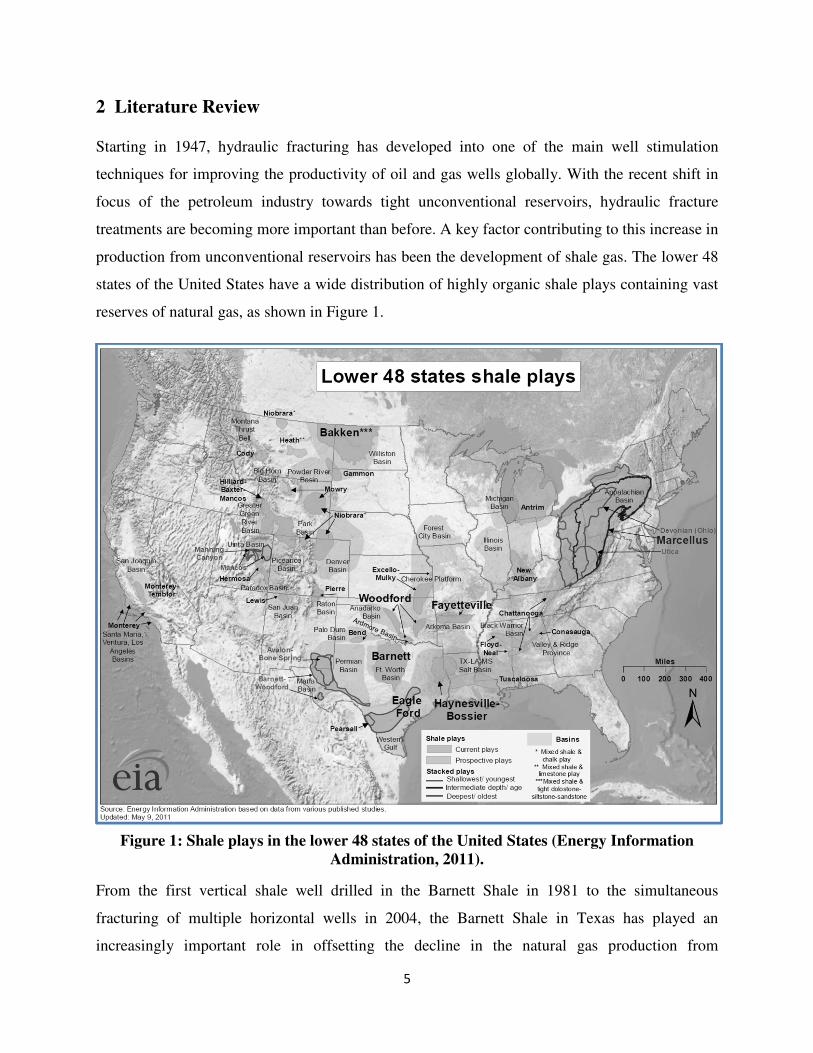
production from unconventional reservoirs has been the development of shale gas. The lower 48
states of the United States have a wide distribution of highly organic shale plays containing vast
reserves of natural gas, as shown in Figure 1.
Figure 1: Shale plays in the lower 48 states of the United States (Energy Information
Administration, 2011).
From the first vertical shale well drilled in the Barnett Shale in 1981 to the simultaneous
fracturing of multiple horizontal wells in 2004, the Barnett Shale in Texas has played an
increasingly important role in offsetting the decline in the natural gas production from
6
conventional resources (Halliburton, 2008 and King, 2010). It has led to the development of
technology to unlock the gas reserves from the low permeability shale gas reservoirs. Much
research is currently being carried out, both in the industry and in academia, to exploit the
unconventional shale reservoirs and to produce the remaining trapped natural gas. Until 1999, all
of the common fracturing methods in shale reservoirs included gel or foam fluids, with and
without proppant (King, 2010); but with the success of slickwater fracturing in the Barnett and
Antrim Shales, more importance has been given to develop slickwater frac materials over the
past decade and to understand the principles related to slickwater fracturing. One such important
aspect, which hasn’t been given enough attention previously, is to understand the proppant
transport during slickwater fracturing in complex fracture systems. An understanding of how
efficiently the proppant is transported from the primary fracture into secondary (and tertiary)
fractures can possibly help in designing the hydraulic fracture treatments more effectively.
2.1 Hydraulic Fracturing in a Naturally Fractured Reservoir
Natural fractures are present in nearly all shale formations and the existence of primary,
secondary and tertiary fractures have been confirmed from various outcrops (King, 2010).
Natural gas production from nano-Darcy fractured shale reservoirs relies heavily on the drilling
of horizontal wells and hydraulic fracture stimulation. Over the past decade, shale formations
have been stimulated with low-proppant-concentration, high-pump-rate, water-based hydraulic
fracture treatments, commonly referred to as slickwater fracture treatments. Based on the studies
carried out, the subcritical crack index for the shale plays have been found to be high; which
confirms the presence of fracture clustering (Gale and Holder, 2010). Microseismic monitoring
of hydraulic fracture treatments has also indicated fracture propagation away from the maximum
horizontal stress direction, which is speculated to be due to the presence of natural fractures.
From a reservoir standpoint, the presence of these natural fractures might increase the
permeability locally but could possibly result in complex fracture geometry during the fracture
stimulation.
Due to the presence of natural fractures, natural gas production from the shale reservoirs is
highly dependent on the Stimulated Reservoir Volume (King, 2010). The results from
microseismic monitoring in the Barnett Shale show the reactivation of these calcite-filled natural
fractures during the stimulation, which in turn improves the efficiency of the fracture treatment
7
(Gale et al., 2007). Therefore, for hydraulic fracture treatment design, knowledge of both the
direction of maximum horizontal stress and the geometry of the natural fractures is important.
2.2 Slickwater Fracturing Technology
Slickwater fracturing, sometimes referred to as “waterfrac” or “friction-reduced frac”, has been
defined as a hydraulic fracture treatment which utilizes large amounts of water along with
polyacrylamide friction reducer (or low concentrations of linear gel, generally 0.5-20lb/Mgals),
clay stabilizer, surfactant and low concentrations of proppant to economically produce natural
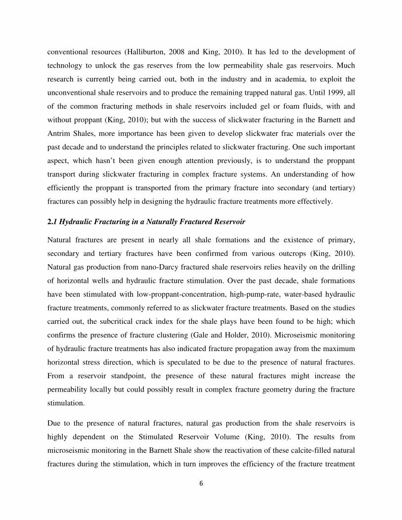
gas from low-permeability reservoirs. The first slickwater treatment was pumped in 1997 by
Mitchell Energy in the Barnett Shale and delivered better results than foam and gel fracs, as
shown in Figure 2.
Figure 2: Refracs of shale well in Barnett Shale – Mitchell Energy (from King, 2010).
Production results from other shale formations also show that the fracture treatments carried out
using slickwater with low proppant concentrations resulted in equal or better performance than
offset conventional wells stimulated with gel/foam fracs (King, 2010). There are several reasons
that may explain this behavior: 1) reduced gel damage within the fracture, 2) reactivation of
8
healed natural fractures, fissures and micro-cracks to increase the stimulated reservoir volume, 3)
optimal dimensionless fracture conductivity, 4) pressure dependent leakoff without significant
loss of fluid into the shale pores, and 5) overall project economics.
However, due to its low viscosity, slickwater fluid shows poor proppant transport characteristics
and has rapid proppant settling. As a result, most slickwater treatments include very low
proppant concentrations, typically in the range of 0.25-2 ppg. Also, in order to achieve similar
fracture conductivity as in the case of cross-linked fracture treatments, slickwater treatments
usually involve pumping of millions of pounds of proppant along with tremendous volumes of
water. Maximum pump rates are in the vicinity of 100 bpm and pump times can exceed six
hours. Unlike the case of cross-linked gels, the use of low-viscosity slickwater results in long
narrow fractures in the reservoir without excessive height growth.
2.3 Proppant Transport
The productivity of a hydraulically fractured well depends on having a fracture which is
effectively propped over the bulk of its length and height. However, good or adequate proppant
transport is a central issue in slickwater fracture treatments because of the low viscosity of the
fracturing fluid. Proppant transport within a fracture is influenced by a number of factors
including: fracture width, injection rate, fluid leak-off, fluid rheology, density difference between
the fluid and the proppant, and proppant size (Palisch et al., 2008, and King, 2010). The
hydraulic fracture simulators available in the industry can predict the proppant transport
associated with gelled fluids fairly well but don’t have the capability to predict proppant
transport in slickwater fracturing associated with complex fracture networks. The proppant
settling is fundamentally governed by Stoke’s Law but is complicated because of (Gadde et al.,
2004, Dayan et al., 2009, Palisch et al., 2008, and King, 2010):
a) Dynamic state of the fluid (as the flow occurs along the fracture);
b) Fracture wall effects;
c) Change in settling velocities and rheology while ramping up the proppant concentration
during the fracture treatment; and,
d) Turbulence and inertial effects (caused by high fluid velocity).
9
Numerous laboratory experiments have been carried out in the past to understand the proppant
transport in low-viscosity fluids in vertical fractures (Kern et al., 1959, Medlin et al., 1985, and
Woodworth and Miskimins, 2007). These slot flow model experiments usually involved
pumping slurry (water and sand) along single vertical plane with constant height and slot width.
Although the flow occurred in between smooth Plexiglas plates without any fluid leakoff,
performing these tests provided a visual sense of proppant movement within the fractures. Kern
et al. (1959) conducted the first slot flow experiment by injecting water and sand at constant
rates. As the slot was closed from the top and the bottom, the slurry flowed horizontally and
because of the poor sand-carrying capacity of the water, the sand settled to the bottom before
moving too far and started building a mound or “dune” of proppant. It was found that the fluid
velocity in the gap between the settled sand and the top of the slot increases as more sand settles
and decreases the gap size. The proppant mound continues to grow until the gap between the
settled sand and the top of the slot reaches a critical value. At and above the critical (or
equilibrium) velocity, the proppant transport in the slot is governed by fluidization and
sedimentation (Palisch et al., 2008). During fluidization, the fluid turbulence re-suspends the
sand off the stationary mound and sedimentation occurs as the proppant is transported further
down the fracture. As the injection is continued, the sand bed eventually stabilizes and reaches
an “equilibrium height” or a steady “traction carpet”. The “equilibrium height” of the sand bed
was found to be a function of fluid velocity, sand concentration and the falling rate of the sand
(which is a function of proppant size and type). As a result of fluidization and sedimentation, the
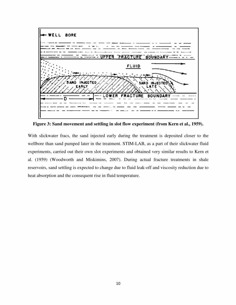
sand bed continues to grow in length as sand continues to be pumped, as shown in Figure 3.
10
Figure 3: Sand movement and settling in slot flow experiment (from Kern et al., 1959).
With slickwater fracs, the sand injected early during the treatment is deposited closer to the
wellbore than sand pumped later in the treatment. STIM-LAB, as a part of their slickwater fluid
experiments, carried out their own slot experiments and obtained very similar results to Kern et
al. (1959) (Woodworth and Miskimins, 2007). During actual fracture treatments in shale
reservoirs, sand settling is expected to change due to fluid leak-off and viscosity reduction due to
heat absorption and the consequent rise in fluid temperature.
11
3 Objectives
The main task of this proposed thesis research is to develop a laboratory model to study proppant
transport in complex fracture network. At this stage, the tools are not available to estimate the
propped fracture lengths and heights and also whether the proppant “turns” the corner or not in
presence of secondary and tertiary fractures.
The proposed research is aimed to achieve the following objectives:
1. Develop and build an experimental laboratory apparatus with a series of slot
configurations, representing different complex fracture scenarios, using acrylic boxes and
Plexiglas. Each slot system will consist of a main slot (fracture) with a varying number of
secondary slots placed at 90O angles to the main slot and tertiary fractures at 90
O angles
to the secondary slots;
2. Evaluate proppant transport through a series of slot configurations by varying the slot
width, proppant size, proppant concentration and pump rate; and,
3. Based on the laboratory test results, develop a correlation or series of correlations that
helps to understand slickwater proppant transport in complex fracture systems. Such a
correlation(s) can possibly help with the designs of hydraulic fracture treatments by
focusing on parameters that enhance transport.
12
4 Methodology
For each experiment, water and sand is to be injected using a submersible pump at a constant
flow rate through an acrylic box configuration representing complex fracture networks. Although
experiments will be carried out with vertical fractures initially, the slot configurations will later
be modified to mimic horizontal fractures as well. General procedures can be summarized as
follows:
1. Arrange the acrylic boxes to represent multiple complex fracture networks by making
different configurations;
2. Fill the water tank with tap water;
3. Adjust the flow meter to the desired value;
4. Start injecting water alone by turning on the submersible pump and achieving flow
equilibrium by adjusting the valves on the discharge manifold for leak-off;
5. Start adding the sand from the sand hopper at the desired rate;
6. Record the flow rate and observe the proppant transport through the acrylic box
configuration. Make sure the cameras are turned on to record the proppant flow;
7. Make the required measurements and stop pumping;
8. Wait until the water has drained through the leak-off points in the system. Clean the sand
remaining in the Plexiglas frame; and,
9. Repeat steps ‘1’ to ‘8’ as needed for the next experiment. Parameters to be varied include
flow rate, sand concentration, slot width and proppant diameter.
NOTE: Pressures will not be recorded during the experiment.
4.1 Experimental Parameters and Test Cases
For this study, in addition to varying the slot complexity, parameters including slot width,
proppant size, proppant concentration, and pump rate will be varied to observe how they affect
the proppant transport in these slot systems. Proppant/sand will be dyed to make sand movement
more visible during the experiments. Proppant sizes will be 30/70 and 100 mesh. Basic slot
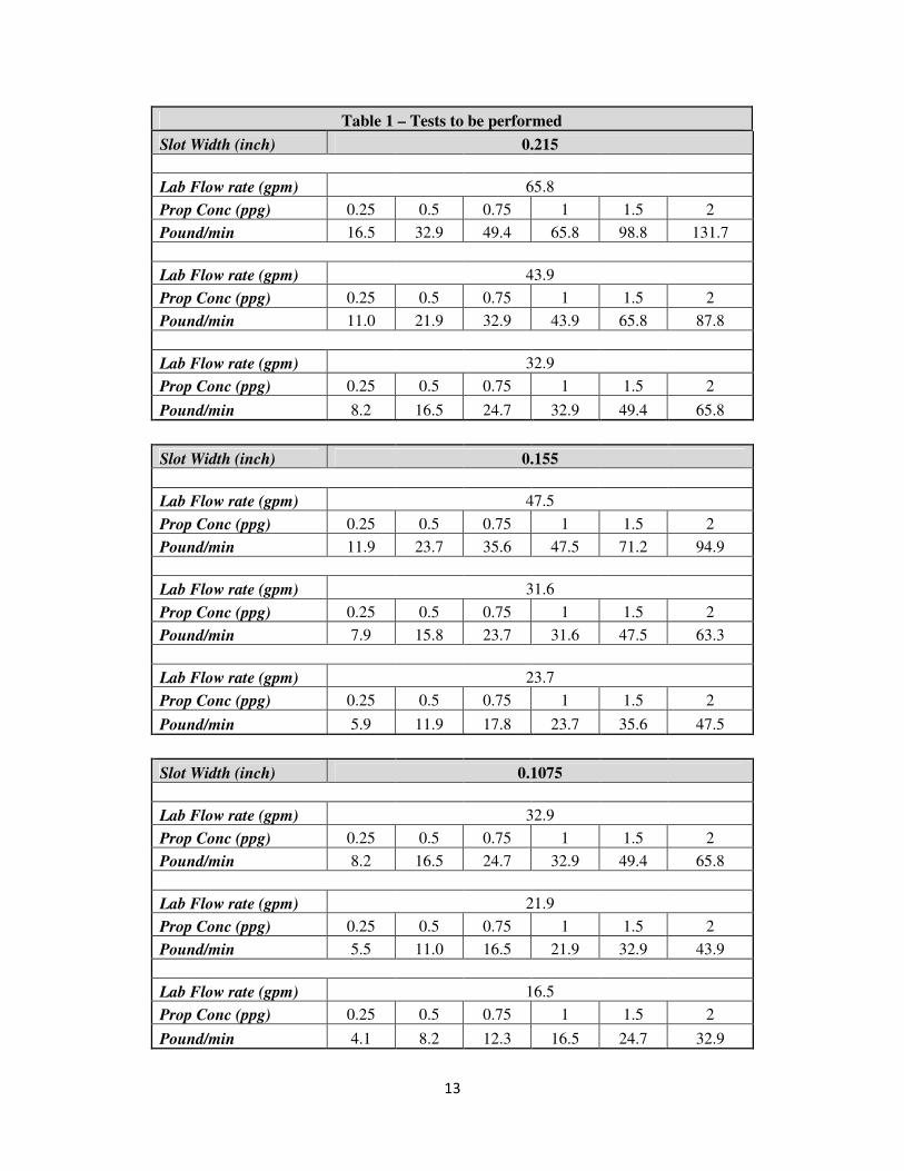
widths will be 0.215”, 0.155” and 0.1075”. Table 1 show a matric of the anticipated tests.
13
Table 1 – Tests to be performed
Slot Width (inch) 0.215
Lab Flow rate (gpm) 65.8
Prop Conc (ppg) 0.25 0.5 0.75 1 1.5 2
Pound/min 16.5 32.9 49.4 65.8 98.8 131.7
Lab Flow rate (gpm) 43.9
Prop Conc (ppg) 0.25 0.5 0.75 1 1.5 2
Pound/min 11.0 21.9 32.9 43.9 65.8 87.8
Lab Flow rate (gpm) 32.9
Prop Conc (ppg) 0.25 0.5 0.75 1 1.5 2
Pound/min 8.2 16.5 24.7 32.9 49.4 65.8
Slot Width (inch) 0.155
Lab Flow rate (gpm) 47.5
Prop Conc (ppg) 0.25 0.5 0.75 1 1.5 2
Pound/min 11.9 23.7 35.6 47.5 71.2 94.9
Lab Flow rate (gpm) 31.6
Prop Conc (ppg) 0.25 0.5 0.75 1 1.5 2
Pound/min 7.9 15.8 23.7 31.6 47.5 63.3
Lab Flow rate (gpm) 23.7
Prop Conc (ppg) 0.25 0.5 0.75 1 1.5 2
Pound/min 5.9 11.9 17.8 23.7 35.6 47.5
Slot Width (inch) 0.1075
Lab Flow rate (gpm) 32.9
Prop Conc (ppg) 0.25 0.5 0.75 1 1.5 2
Pound/min 8.2 16.5 24.7 32.9 49.4 65.8
Lab Flow rate (gpm) 21.9
Prop Conc (ppg) 0.25 0.5 0.75 1 1.5 2
Pound/min 5.5 11.0 16.5 21.9 32.9 43.9
Lab Flow rate (gpm) 16.5
Prop Conc (ppg) 0.25 0.5 0.75 1 1.5 2
Pound/min 4.1 8.2 12.3 16.5 24.7 32.9
14
4.2 Experimental Set Up
The experimental apparatus for this research will include pumping slickwater slurry through the
testing system developed to study the proppant transport during slickwater fracture treatment. As
mentioned previously, the testing system will include several slot configurations as described in
section 4.2.3.
4.2.1 Slickwater Slurry
For this experimental study, tap water with different sizes of proppant (30/70 and 100 Mesh)
will be used to mimic the slickwater fracturing slurry.
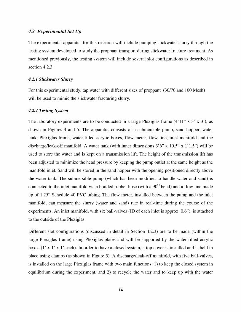
4.2.2 Testing System
The laboratory experiments are to be conducted in a large Plexiglas frame (4’11” x 3’ x 3’), as
shown in Figures 4 and 5. The apparatus consists of a submersible pump, sand hopper, water
tank, Plexiglas frame, water-filled acrylic boxes, flow meter, flow line, inlet manifold and the
discharge/leak-off manifold. A water tank (with inner dimensions 3’6” x 10.5” x 1’1.5”) will be
used to store the water and is kept on a transmission lift. The height of the transmission lift has
been adjusted to minimize the head pressure by keeping the pump outlet at the same height as the
manifold inlet. Sand will be stored in the sand hopper with the opening positioned directly above
the water tank. The submersible pump (which has been modified to handle water and sand) is
connected to the inlet manifold via a braided rubber hose (with a 90O bend) and a flow line made
up of 1.25” Schedule 40 PVC tubing. The flow meter, installed between the pump and the inlet
manifold, can measure the slurry (water and sand) rate in real-time during the course of the
experiments. An inlet manifold, with six ball-valves (ID of each inlet is approx. 0.6”), is attached
to the outside of the Plexiglas.
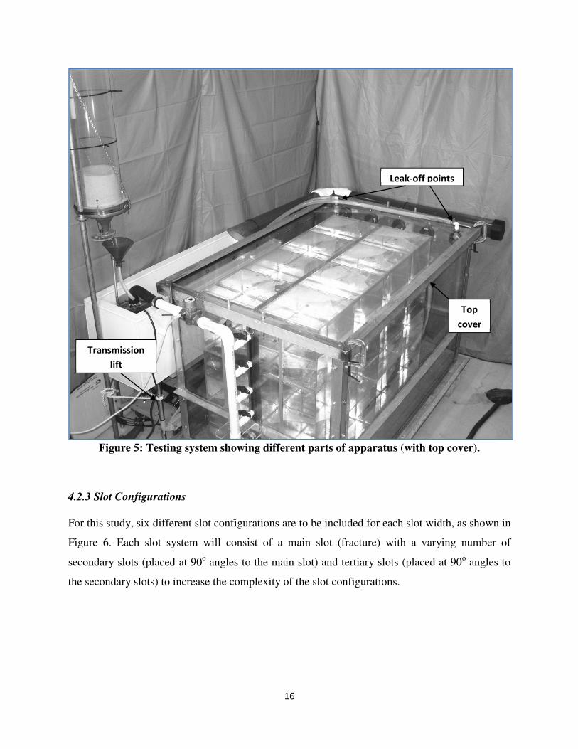
Different slot configurations (discussed in detail in Section 4.2.3) are to be made (within the
large Plexiglas frame) using Plexiglas plates and will be supported by the water-filled acrylic
boxes (1’ x 1’ x 1’ each). In order to have a closed system, a top cover is installed and is held in
place using clamps (as shown in Figure 5). A discharge/leak-off manifold, with five ball-valves,
is installed on the large Plexiglas frame with two main functions: 1) to keep the closed system in
equilibrium during the experiment, and 2) to recycle the water and to keep up with the water
15
injection rate. Two leak-off points are also installed on the top cover, to stop accidental
ballooning of the top cover.
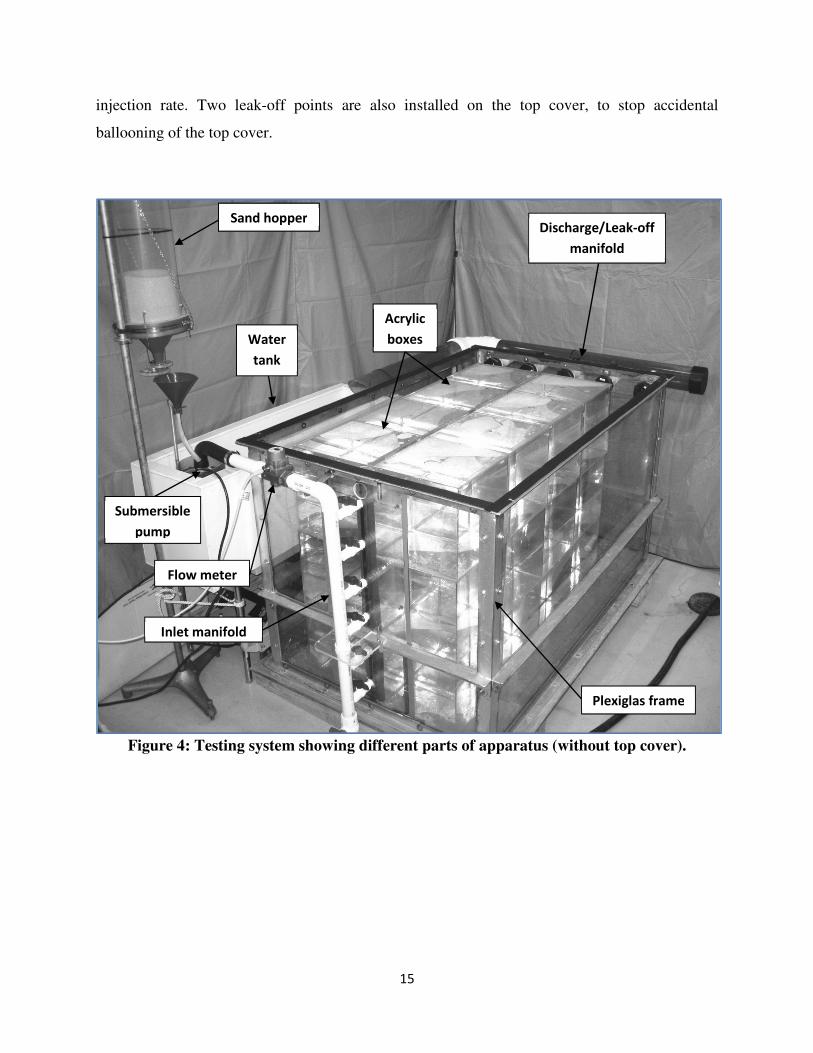
Figure 4: Testing system showing different parts of apparatus (without top cover).
Plexiglas frame
Discharge/Leak-off
manifold
Sand hopper
Inlet manifold
Flow meter
Submersible
pump
Acrylic
boxes Water
tank
16
Figure 5: Testing system showing different parts of apparatus (with top cover).
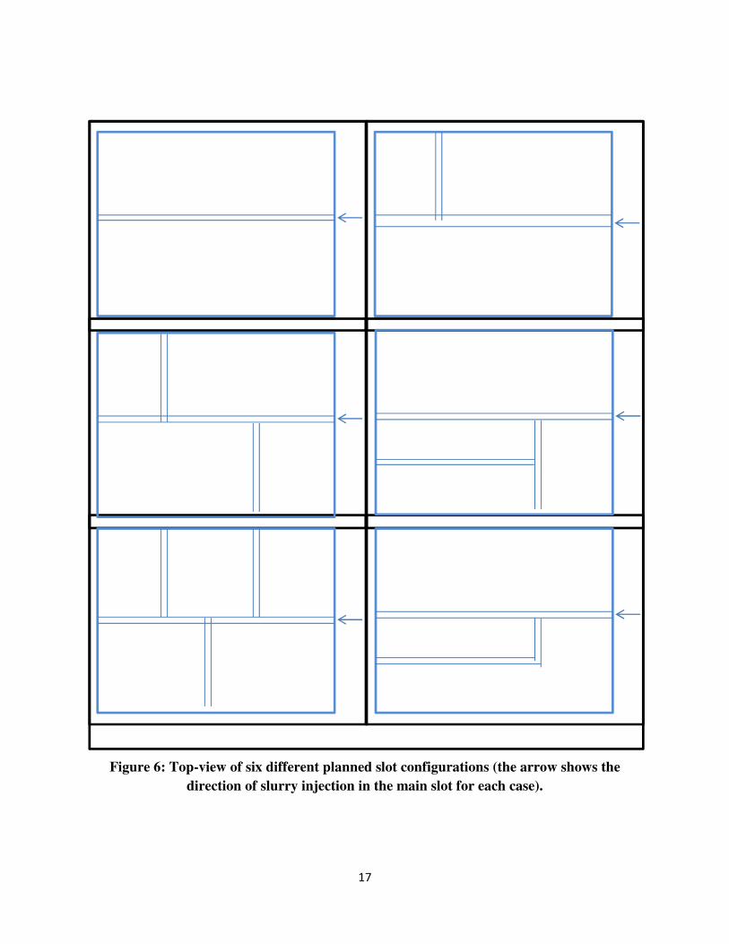
4.2.3 Slot Configurations
For this study, six different slot configurations are to be included for each slot width, as shown in
Figure 6. Each slot system will consist of a main slot (fracture) with a varying number of
secondary slots (placed at 90o angles to the main slot) and tertiary slots (placed at 90
o angles to
the secondary slots) to increase the complexity of the slot configurations.
Transmission
lift
Top
cover
Leak-off points
17
Figure 6: Top-view of six different planned slot configurations (the arrow shows the
direction of slurry injection in the main slot for each case).
18
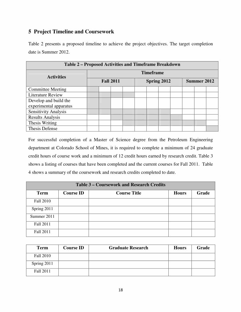
5 Project Timeline and Coursework
Table 2 presents a proposed timeline to achieve the project objectives. The target completion
date is Summer 2012.
Table 2 – Proposed Activities and Timeframe Breakdown
Activities Timeframe
Fall 2011 Spring 2012 Summer 2012
Committee Meeting
Literature Review
Develop and build the
experimental apparatus
Sensitivity Analysis
Results Analysis
Thesis Writing
Thesis Defense
For successful completion of a Master of Science degree from the Petroleum Engineering
department at Colorado School of Mines, it is required to complete a minimum of 24 graduate
credit hours of course work and a minimum of 12 credit hours earned by research credit. Table 3
shows a listing of courses that have been completed and the current courses for Fall 2011. Table
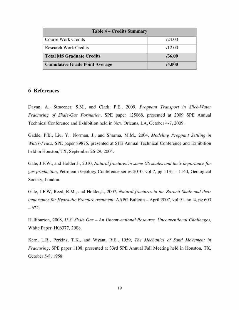
4 shows a summary of the coursework and research credits completed to date.
Table 3 – Coursework and Research Credits
Term Course ID Course Title Hours Grade
Fall 2010
Spring 2011
Summer 2011
Fall 2011
Fall 2011
Term Course ID Graduate Research Hours Grade
Fall 2010
Spring 2011
Fall 2011
19
Table 4 – Credits Summary
Course Work Credits /24.00
Research Work Credits /12.00
Total MS Graduate Credits /36.00
Cumulative Grade Point Average /4.000
6 References
Dayan, A., Stracener, S.M., and Clark, P.E., 2009, Proppant Transport in Slick-Water
Fracturing of Shale-Gas Formation, SPE paper 125068, presented at 2009 SPE Annual
Technical Conference and Exhibition held in New Orleans, LA, October 4-7, 2009.
Gadde, P.B., Liu, Y., Norman, J., and Sharma, M.M., 2004, Modeling Proppant Settling in
Water-Fracs, SPE paper 89875, presented at SPE Annual Technical Conference and Exhibition
held in Houston, TX, September 26-29, 2004.
Gale, J.F.W., and Holder,J., 2010, Natural fractures in some US shales and their importance for
gas production, Petroleum Geology Conference series 2010, vol 7, pg 1131 – 1140, Geological
Society, London.
Gale, J.F.W, Reed, R.M., and Holder,J., 2007, Natural fractures in the Barnett Shale and their
importance for Hydraulic Fracture treatment, AAPG Bulletin – April 2007, vol 91, no. 4, pg 603
– 622.
Halliburton, 2008, U.S. Shale Gas – An Unconventional Resource, Unconventional Challenges,
White Paper, H06377, 2008.
Kern, L.R., Perkins, T.K., and Wyant, R.E., 1959, The Mechanics of Sand Movement in
Fracturing, SPE paper 1108, presented at 33rd SPE Annual Fall Meeting held in Houston, TX,
October 5-8, 1958.
20
King, G.E., 2010, Thirty Years of Gas Shale Fracturing: What Have We Learned?, SPE paper
133456, presented at SPE Annual Technical Conference and Exhibition held in Florence, Italy,
September 19-22, 2010.
Medlin, W.L., Sexton, J.H., and Zumwalt, G.L., 1985, Sand Transport Experiments in Thin
Fluids, SPE paper 14469, presented at 60th SPE Annual Technical Conference and Exhibition
held in Las Vegas, NV, September 22-25, 1985.
Palisch, T.T., Vincent, M.C., and Handren, P.J., 2008, Slickwater Fracturing – Food for
Thought, SPE paper 115766, presented at 2008 SPE Annual Technical Conference and
Exhibition held in Denver, CO, September 21-24, 2008.
US Energy Information Administration (EIA), 2011, World Shale Gas Resources: An initial
Assessment of 14 Regions Outside the United States, U.S. Department of Energy, Washington,
DC 20585, April 2011.
Woodworth, T.R., and Miskimins, J.L., 2007, Extrapolation of Laboratory Proppant Placement
Behavior to the Field in Slickwater Fracturing Application, SPE paper 106089, presented at
2007 SPE Hydraulic Fracturing Technology Conference held in College Station, TX, January 29-
31, 2007.
http://www.eia.gov/oil_gas/rpd/shaleusa2.pdf. Accessed, September 05, 2011.
7 Research Sponsor
This research work will be undertaken at the Petroleum Engineering department, Colorado
School of Mines and is sponsored solely by Southwestern Energy. Southwestern Energy is an
independent energy company, primarily engaged in domestic natural gas and crude oil
production and has major operations in Texas, Pennsylvania and New Brunswick, Canada. With
rapidly growing activity in the Fayetteville and Marcellus Shale plays, results from this research
can possibly help the company in improving the effectiveness of the hydraulic fracturing
treatments.