Embed Size (px)
Citation preview

Production Management B – Spring Semester 2009
Product Lifecycle Management I L08 P. 0
Lecture 08
Production Management B
Lecture 08Product Lifecycle Management I
Organisation:Dipl.-Ing. Michael JungSteinbachstr. 53BRaum 528Tel.: [email protected]
Laboratory for Machine Tools and Production Engineering
Chair of Production EngineeringProf. Dr.-Ing. Dipl.-Wirt. Ing. G. Schuh
Chair of Production ManagementProf. Dr.-Ing. A. Kampker

Production Management B – Spring Semester 2009
Product Lifecycle Management I L08 P. 1
Lecture 08
Index:
Index Page 1
Schedule Page 2
Glossary Page 3
Target of this lecture Page 4
LectureProduct Lifecycle Management (PLM) Page 6
Important of information flows within CAx-applications Page 9
Differentiation between CAD, PDM and PLM Page 10
Computer-internal display formats of CAD-modelling Page 13
Objectives of CAD-interface applications Page 19
Integration of CAD and FEA Page 25
Final statement Page 28
Bibliography Page 29

Production Management B – Spring Semester 2009
Product Lifecycle Management I L08 P. 2
Lecture 08
Schedule:
No. Date Responsible
L1 27.04.2009 Mr. Rittstieg 0241 80 20396
L2 04.05.2009 Mr. Bartoscheck 0241 80 28203
L3 18.05.2009 Mr. Fuchs 0241 80 26265
L4 25.05.2009Mr. Reil
0241 80 27964
L5 08.06.2009 Mr. Potente 0241 80 27387
L6 15.06.2009 Mr. Bauhoff (fir) 0241 47705-439
L7 22.06.2009 Mr. Hoeschen 0241 80 27382
L8 29.06.2009 Mr. Jung 0241 80 27392
L9 06.07.2009 Mr. Rauhut 0241 80 28206
L11 13.07.2009Mr. Koch
0241 80 25321
L12 20.07.2009 Mr. Cuber (fir) 0241 47705-420
Customer Relations Management
Enterprise Ressource Planning I
Enterprise Ressource Planning II
Topic
IT in Production Management
Enterprise Ressource Planning III
Product Lifecycle Management II
Digitale Plant Planning and Simulation
Business Engineering - Method of selecting IT-Systems (Trovarit)
Supply Chain Management I
Supply Chain Management II
Product Lifecycle Management I

Production Management B – Spring Semester 2009
Product Lifecycle Management I L08 P. 3
Lecture 08
Glossary:
CAD (Computer Aided Design, see annotation figure 7, page 11)
CAM (Computer Aided Manufacturing) refers to computer applications for controlling manufacturing. This includes the direct controlling of machine tools, machining centers or assembly lines as well as logistic problems, e.g. controlling of material flow or registration of operating data.
CAE (Computer Aided Engineering) refers to all activities within CAD, CAP*, CAM and CAQ**, i.e. all computer applications in technical divisions of companies.
CAP (Computer Aided Planning) is the computer adoption in process- and production planning, e.g. generation of NC-information, working plans or parts lists.
CAQ (Computer Aided Quality Assurance) is the computer adoption in quality assurance e.g. generation of check programs, plans or statistical analysis of check values.
Product Data Management (PDM) is a technical information management system for manufacturing companies and engineering service providers. It provides an information platform for product development with core competences like system integration, data management, process management, project management and authorization management.
Engineering Data Management (EDM) is another expression (synonym) for PDM.
Production Management B – Spring Semester 2009
Product Lifecycle Management I L08 P. 4
Lecture 08
Target of this lecture:
The lecture introduces to the topic of Product Lifecycle management and presents current IT tools in the development process. The lecture explains different computer-internal display formats of CAD-Modeling. The lecture shows the importance of information flows within CAx-applications and the objectives and problems of CAD-interface applications.

Production Management B – Spring Semester 2009
Product Lifecycle Management I L08 P. 5
Lecture 08
Seite 5© WZL/Fraunhofer IPT
Product Lifecycle Management (PLM)
… includes management and controlling of product data - during the complete product life cycle along the enhanced logistics supply chain -beginning from design engineering and production beyond sales (distribution) and ending with maintenance.
Integrated PLM offers access to all product and process data of the complete life cycle of a product.
The functionality exceeds the system.Prof. Dr. Stucky, aifb, Karlsruhe
PLM
CSC PLOENZKE AG
ProductLifecycle
Management
Productdevelopment
Manufacturing & assembly
Market
Service &maintenance
Distribution &shipping
Productionpreparation
Product planningDisassembly
& recycling
The Term Product Lifecycle Management is used differently by the literature and by system providers. Generally three different approaches are distinguished:
PLM as a synonym for Product-Data-Management:PLM is a no new systemclass and no new form of PDM-System, but the
consequent transformation to on WEB-technology based location- and companie overlapping application of the PDM-core-competences datamanagement, process management and system integration in all areas and phases of the industrial added value.
PLM as integral integrational platform of different IT-systems:PLM is a engineering-driven PDM system. PDM is supporting every employee
during the whole product life cycle by administration of all related data and processes.
PLM as integral organisational concept of mangament for dataadministration an information availibilty:

Production Management B – Spring Semester 2009
Product Lifecycle Management I L08 P. 6
Lecture 08
Seite 6© WZL/Fraunhofer IPT
Development of PLM with function integration of CAx and ERP
Figure 2
PLM – horizontal Integration
IntersectionConfigurationParts management Parts lists management
MRP: Material Requirement PlanningMRP I: Material Resource Planning IMRP II: Management Resource Planning IIERP: Enterprise Resource Planning
timetime
2D-CAD1960
MRP1950
Notes:CAD (Computer Aided Design, see annotation figure 7, page 11)
CAM (Computer Aided Manufacturing) refers to computer applications for controlling manufacturing. This includes the direct controlling of machine tools, machining centres or assembly lines as well as logistic problems, e.g. controlling of material flow or registration of operating data.
CAE (Computer Aided Engineering) refers to all activities within CAD, CAP*, CAM and CAQ**, i.e. all computer applications in technical divisions of companies.
*CAP (Computer Aided Planning) is the computer adoption in process- and production planning, e.g. generation of NC-information, working plans or parts lists.
**CAQ (Computer Aided Quality Assurance) is the computer adoption in quality assurance e.g. generation of check programmes, plans or statistical analysis of check values.
Product Data Management (PDM) is a technical information management system for manufacturing companies and engineering service providers. It provides an information platform for product development with core competences like system integration, data management, process management, project management and authorisation management.
Engineering Data Management (EDM) is another expression (synonym) for PDM.

Production Management B – Spring Semester 2009
Product Lifecycle Management I L08 P. 7
Lecture 08
Seite 7© WZL/Fraunhofer IPT
Product Lifecycle Management is integrating processes, technologies and humans
Attending process
Product appearance
Productfabrication
Productdevelopment
Marketing Acquisition Salereal
product
Real Produktlife
Produkt-nutzung
Produkt-entsorgung
PLM-System Integrational platformIntegrational platform
Information generatingTools
Modeling Tools(CAD/CAM/CAP)
Calculation- andSimulation Tools (CAE)
Visualising Tools(DMU, VR, AR)
Information andCollaborationmanagement
Product Data Management
Supply Chain Mangement
Customer RelationshipMangement
Anmerkungen zur Folie:Product development process from product life cycle viewThe product life cycle consists of the main phases
Product appearance (planning, development)Product development (process planning, operative production) and the real Product life (Use and disposal)
The main process phases are supplemented by attending processes
Term plurality in context with PLMReasons for the term plurality:
Chronological further development of the systems (e.g. Enhancement of functions)Different Marketing strategies of the software-producersAs well used nowadays terms are EDM and PDM
Classification „PLM – PDM“:Traditional PDM-Approach: PDM is acting as interface between technical and commercialinformation processing, that means between CAx-systems on the one hand and acquisitionand production on the other hand. Therefore these systems were limited to the development.PLM-Approach: PLM is expanding the PDM-functionalities and has the ability to provideprocess integrating data and information. In addition it is separating the detachement of intern and extern users along the supply chain. PLM supports cooperative forms of collaborationbeyond company boundaries.
Production Management B – Spring Semester 2009
Product Lifecycle Management I L08 P. 8
Lecture 08
Seite 8© WZL/Fraunhofer IPT
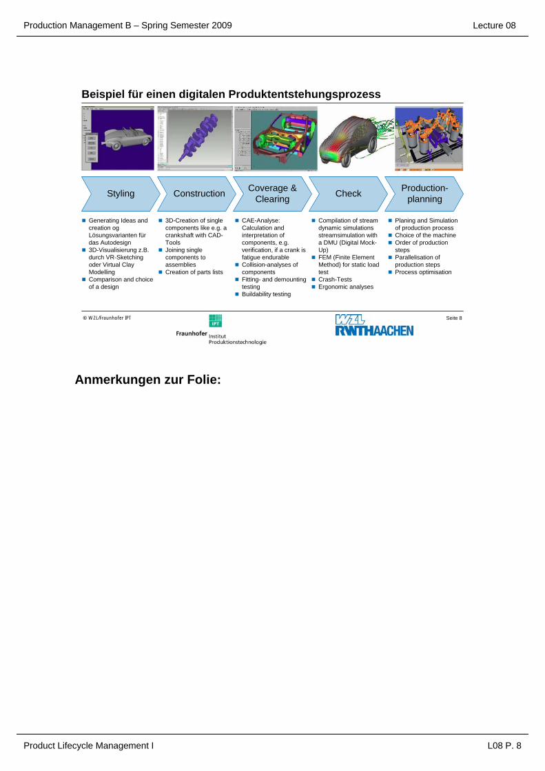
Beispiel für einen digitalen Produktentstehungsprozess
ConstructionStyling Coverage & Clearing Check Production-
planning
Generating Ideas and creation ogLösungsvarianten für das Autodesign3D-Visualisierung z.B. durch VR-Sketchingoder Virtual Clay ModellingComparison and choiceof a design
3D-Creation of singlecomponents like e.g. a crankshaft with CAD-ToolsJoining singlecomponents to assembliesCreation of parts lists
CAE-Analyse: Calculation and interpretation of components, e.g. verification, if a crank isfatigue endurableCollision-analyses of componentsFitting- and demountingtestingBuildability testing
Compilation of streamdynamic simulationsstreamsimulation witha DMU (Digital Mock-Up)FEM (Finite Element Method) for static loadtestCrash-TestsErgonomic analyses
Planing and Simulation of production processChoice of the machineOrder of productionstepsParallelisation of production stepsProcess optimisation
Anmerkungen zur Folie:

Production Management B – Spring Semester 2009
Product Lifecycle Management I L08 P. 9
Lecture 08
Seite 9© WZL/Fraunhofer IPT
Supporting IT-systems for PLM
CAD
CAM
CAD: Computer Aided DesignCAE: Computer Aided EngineeringCAM: Computer Aided Manufacturing
CAP: Computer Aided PlanningCAQ: Computer Aided QualityCRM: Custom Relationship Management
ERP: Enterprise Ressource PlanningPDM: Product Data ManagementPLM: Product Lifecycle Management
SCM: Supply Chain Management
ERP
nach EDM-Report Nr.1, 2003
PLM reference process
CRM
CAQ
PDM
CAQ
SCMCAP
CAE
CAQ
CRM
Market DevelopmentOperations
scheduling &process planning
Productionplanning
Manufacturing & assembly Sales Service &
maintenanceDisassembly & recycling
Notes:It is not that the PLM-IT-systems lead to the idea of PLM but the other way round: PLM-IT-systems represent the functionalities and processes behind the idea of PLM.
The use of a combined basis of PLM-data for development, order processing, configuration etc. implies a new application process routine among the entire product lifecycle.
By realising the simultaneous data access of all persons involved in the product and the process, PLM supports resp. operationalises the idea of Simultaneous Engineering resp. Concurrent Engineering.
PLM reduces redundancies of data within the product life cycle.

Production Management B – Spring Semester 2009
Product Lifecycle Management I L08 P. 10
Lecture 08
Seite 10© WZL/Fraunhofer IPT
Important of information flows within CAx-applications
CAD: Computer Aided DesignCAP: Computer Aided PlanningNC: Numerical ControlERP: Enterprise Resource
PlanningPPS: Production Planning
SystemCAM: Computer Aided
ManufacturingCAQ: Computer Aided
Quality Assurance
EDM/PDM
CAP CAQ
ERP(PPS)
CAD
NC-Programm-ing system
Working plan &Operation plan
Quotationprocessing
Finaldispatch
NC-Programme
Feedback Operations
CAMcontrol centre
Production
customerOrder
Quotation
Dra
win
g
Parts list &drawing
Workingplan
Parts list
Order
Shop-order
Audit-operation
control variable
Measuringdata
Notes:For handling orders respectively manufacturing products an information exchange between different divisions of a company is necessary.
Among other things it deals with drawings, parts lists, working plans etc.. Thus huge amounts of data and complex information contents like geometry data are transferred.
Production Management B – Spring Semester 2009
Product Lifecycle Management I L08 P. 11
Lecture 08
Seite 11© WZL/Fraunhofer IPT
Differentiation between CAD, PDM and PLMIntegration depth
Product structure
Documents
Change and configuration management
Collaboration
Project planningand calculation
CAD
PDM
Projection BasicEngineering
Maintenance& service
Processplanning
Production &assembly
PLMProject management
CollaborativeEngineering Change
management
As-built
Knowledgemanagement
DetailEngineering
Configurationmanagement
Visualization
Constructionchange
Structures
Documentmanagement
Variant configuration
Legende:PLM=Product Lifecycle ManagementPDM=Produkt DatenmanagementCAD=Computer Aided Design
Integration breadth
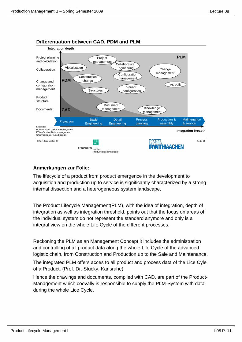
Anmerkungen zur Folie:The lifecycle of a product from product emergence in the development to acquisition and production up to service is significantly characterized by a stronginternal dissection and a heterogeneous system landscape.
The Product Lifecycle Management(PLM), with the idea of integration, depth of integration as well as integration threshold, points out that the focus on areas of the individual system do not represent the standard anymore and only is a integral view on the whole Life Cycle of the different processes.
Reckoning the PLM as an Management Concept it includes the administrationand controlling of all product data along the whole Life Cycle of the advancedlogistic chain, from Construction and Production up to the Sale and Maintenance.
The integrated PLM offers acces to all product and process data of the Lice Cyleof a Product. (Prof. Dr. Stucky, Karlsruhe)
Hence the drawings and documents, compiled with CAD, are part of the Product-Management which coevally is responsible to supply the PLM-System with dataduring the whole Lice Cycle.
Production Management B – Spring Semester 2009
Product Lifecycle Management I L08 P. 12
Lecture 08
Seite 12© WZL/Fraunhofer IPT
History of development of workplaces for design engineering
l1 w1 l2 w2
d3
d4d1
d5
l1
b
d2
d5d5
d5
Abi
lity
for f
urth
erpr
oces
sing
of d
ata
2D-CADsystem
3D-CADsystem Virtual Reality
InteractionImmersion
Intuitional presentation
Digitalprototype
Electronicdrawing boardDrawing board
till 50‘s 60‘s 80‘s 21. century time
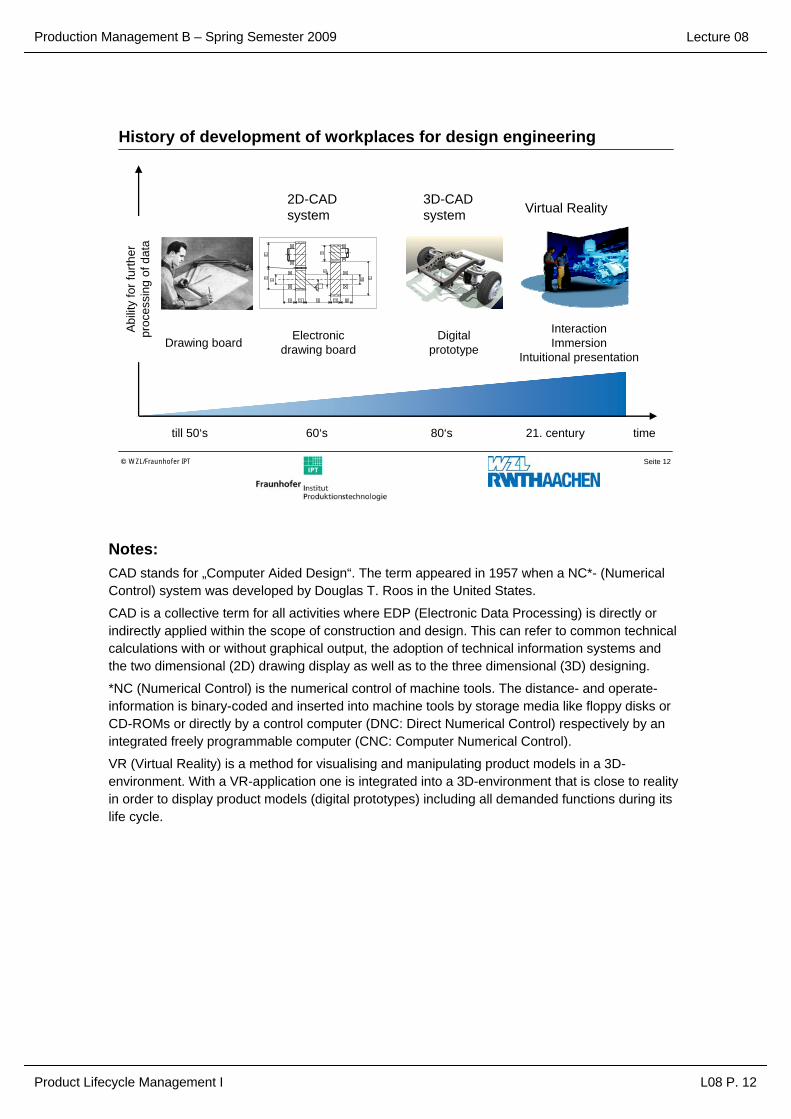
Notes:CAD stands for „Computer Aided Design“. The term appeared in 1957 when a NC*- (Numerical Control) system was developed by Douglas T. Roos in the United States.
CAD is a collective term for all activities where EDP (Electronic Data Processing) is directly or indirectly applied within the scope of construction and design. This can refer to common technical calculations with or without graphical output, the adoption of technical information systems and the two dimensional (2D) drawing display as well as to the three dimensional (3D) designing.
*NC (Numerical Control) is the numerical control of machine tools. The distance- and operate-information is binary-coded and inserted into machine tools by storage media like floppy disks or CD-ROMs or directly by a control computer (DNC: Direct Numerical Control) respectively by an integrated freely programmable computer (CNC: Computer Numerical Control).
VR (Virtual Reality) is a method for visualising and manipulating product models in a 3D-environment. With a VR-application one is integrated into a 3D-environment that is close to reality in order to display product models (digital prototypes) including all demanded functions during its life cycle.

Production Management B – Spring Semester 2009
Product Lifecycle Management I L08 P. 13
Lecture 08
Seite 13© WZL/Fraunhofer IPT
Examples of CAD-application
examples
CAD-
applications
CAD: Computer Aided Design
l1 w1 l2 w2
d3
d4d1
d5
l1
b
d2
d5d5
d5
Quotation processing
Machinedesign
DetailingElectronicdesign
Manufacturing resources
design
Production Management B – Spring Semester 2009
Product Lifecycle Management I L08 P. 14
Lecture 08
Seite 14© WZL/Fraunhofer IPT
Computer-internal display formats of CAD-modelling
-+ =
Translation vectordrillingnotdescribable
2D - line model:point, line
2 ½ D - profile line model:point, line, vector
3D - wire-frame model:point, line
3D - surface model:point, line, surface
3D- CSG-volume model(Constructive Solids Geometry): volume
3D-B-Rep model(Boundary Representation):point, line, surface, volume
Hybrid model:(3D-CSG volume model + 3D-B-Rep model)
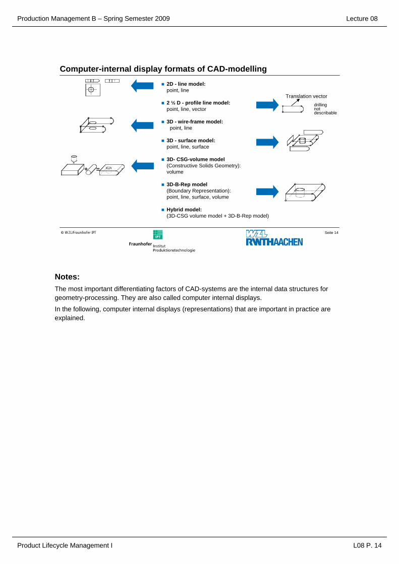
Notes:The most important differentiating factors of CAD-systems are the internal data structures for geometry-processing. They are also called computer internal displays.
In the following, computer internal displays (representations) that are important in practice are explained.
Production Management B – Spring Semester 2009
Product Lifecycle Management I L08 P. 15
Lecture 08
Seite 15© WZL/Fraunhofer IPT
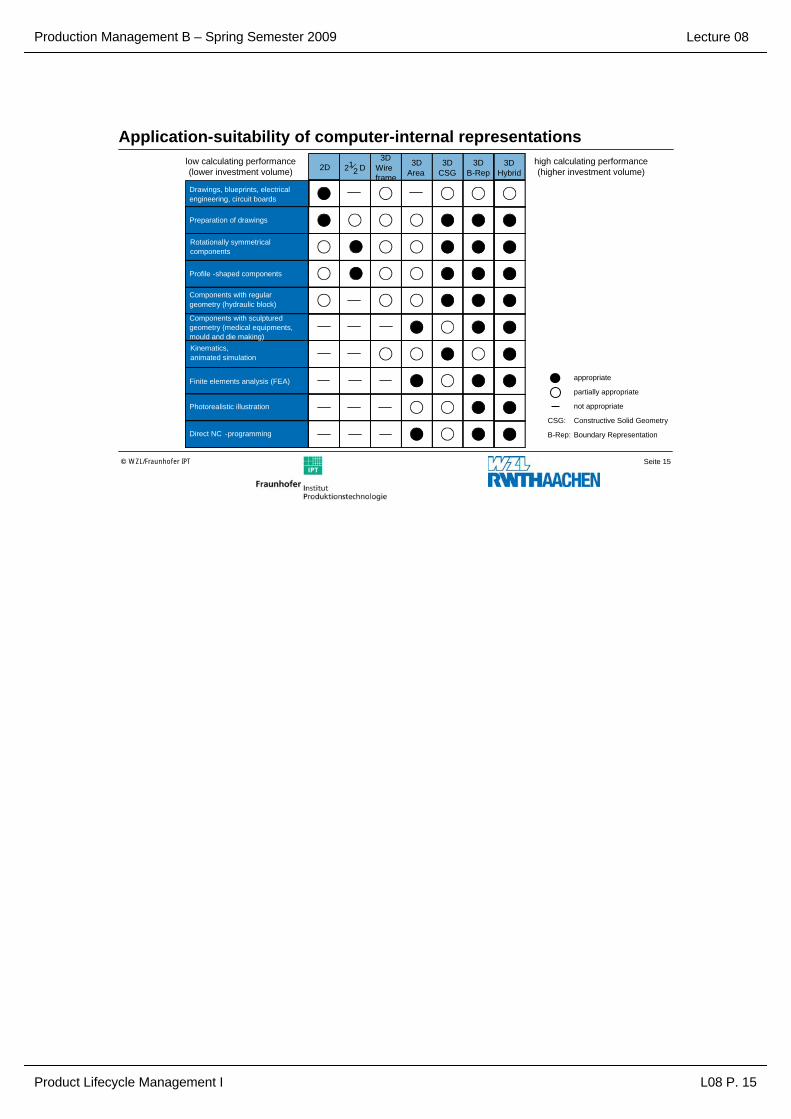
Application-suitability of computer-internal representations3D
B-Rep2D 21
2 D3D
Wireframe
3DArea
3DCSG
3DHybrid
appropriate
partially appropriate
not appropriate
CSG: Constructive Solid Geometry
B-Rep: Boundary Representation
Drawings, blueprints, electricalengineering, circuit boards
Preparation of drawings
Rotationally symmetricalcomponents
Profile -shaped components
Components with regulargeometry (hydraulic block)
Direct NC -programming
Kinematics, animated simulation
Finite elements analysis (FEA)
Photorealistic illustration
Components with sculptured geometry (medical equipments,mould and die making)
high calculating performance(higher investment volume)
low calculating performance(lower investment volume)
Production Management B – Spring Semester 2009
Product Lifecycle Management I L08 P. 16
Lecture 08
Seite 16© WZL/Fraunhofer IPT
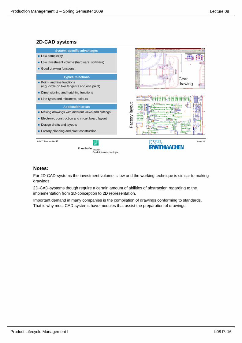
2D-CAD systemsSystem-specific advantages
Low complexity
Low investment volume (hardware, software)
Good drawing functions
Point- and line functions (e.g. circle on two tangents and one point)
Dimensioning and hatching functions
Line types and thickness, colours
Typical functions
Making drawings with different views and cuttings
Electronic construction and circuit board layout
Design drafts and layouts
Factory planning and plant construction
Application areas
Gear drawing
Fact
ory
layo
ut
Notes:For 2D-CAD-systems the investment volume is low and the working technique is similar to making drawings.
2D-CAD-systems though require a certain amount of abilities of abstraction regarding to the implementation from 3D-conception to 2D representation.
Important demand in many companies is the compilation of drawings conforming to standards. That is why most CAD-systems have modules that assist the preparation of drawings.
Production Management B – Spring Semester 2009
Product Lifecycle Management I L08 P. 17
Lecture 08
Seite 17© WZL/Fraunhofer IPT
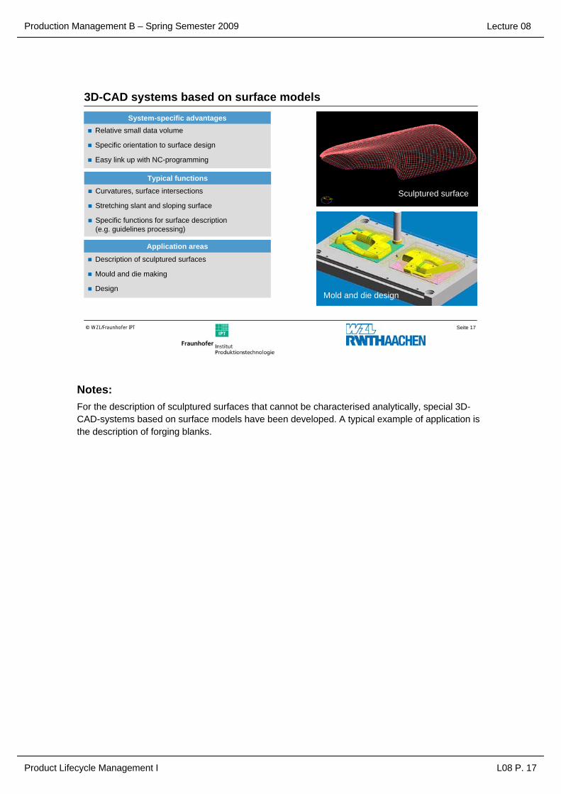
System-specific advantagesRelative small data volume
Specific orientation to surface design
Easy link up with NC-programming
Curvatures, surface intersections
Stretching slant and sloping surface
Specific functions for surface description(e.g. guidelines processing)
Typical functions
Description of sculptured surfaces
Mould and die making
Design
Application areas
3D-CAD systems based on surface models
Sculptured surface
Mold and die design
Notes:For the description of sculptured surfaces that cannot be characterised analytically, special 3D-CAD-systems based on surface models have been developed. A typical example of application is the description of forging blanks.

Production Management B – Spring Semester 2009
Product Lifecycle Management I L08 P. 18
Lecture 08
Seite 18© WZL/Fraunhofer IPT
3D-CAD systems based on CSG-modelsSystem-specific advantages
Volume information available
Quick generation of simple geometries
History of development available
Intersection of volume bodies
Volume calculation
Translation- and rotation functions
Typical functions
Animated simulation
Plant engineering and construction
Regular geometries
Application areas
FactoryA
nim
ated
sim
ulat
ion
Valve
Cams
Valvehead
Lever
Notes:For generating of analytically describable geometries, CAD-systems based on CSG-models (Constructive Solids Geometry) are suitable.
Thereby work pieces are described by volume bodies that are combined by Boolean Operations (addition, subtraction and deviation).
Sculptured surfaces cannot be created by this means. The connection to NC-programmes is difficult because of missing surface information.
Production Management B – Spring Semester 2009
Product Lifecycle Management I L08 P. 19
Lecture 08
Seite 19© WZL/Fraunhofer IPT
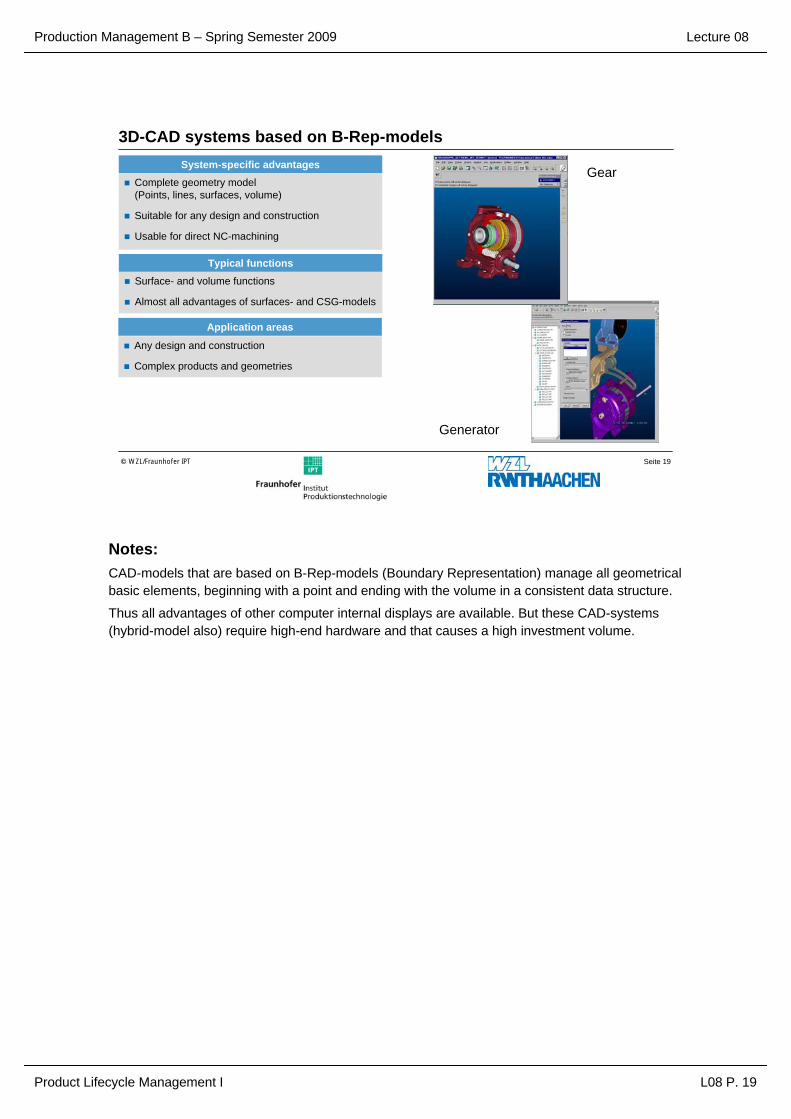
3D-CAD systems based on B-Rep-modelsSystem-specific advantages
Complete geometry model(Points, lines, surfaces, volume)
Suitable for any design and construction
Usable for direct NC-machining
Surface- and volume functions
Almost all advantages of surfaces- and CSG-models
Typical functions
Any design and construction
Complex products and geometries
Application areas
Gear
Generator
Notes:CAD-models that are based on B-Rep-models (Boundary Representation) manage all geometrical basic elements, beginning with a point and ending with the volume in a consistent data structure.
Thus all advantages of other computer internal displays are available. But these CAD-systems (hybrid-model also) require high-end hardware and that causes a high investment volume.

Production Management B – Spring Semester 2009
Product Lifecycle Management I L08 P. 20
Lecture 08
Seite 20© WZL/Fraunhofer IPT
Objectives of CAD-interface applications
Objects of CAD-interface applications
Transfer of CAD-data
Avoidance of multiple inputs
Reduction of cycle times
Prevention of data inconsistencies and redundancies
CADCAD
Rapid prototyping Numerical controlled machine tools
Finite Element Analysis
Virtual Reality
Digital Mock-Up
Engineering data management
Notes:The cost-intensive adoption of CAD-systems is only effective and economical if the produced data can be used by different divisions within the company and by customers respectively distributors.
Interfaces for exchanging data are necessary because normally different CAD-configurations are used by sender and receiver.
In connection with simultaneous engineering and design cooperation the importance of high-end data and information interfaces is very high.

Production Management B – Spring Semester 2009
Product Lifecycle Management I L08 P. 21
Lecture 08
Seite 21© WZL/Fraunhofer IPT
Data exchange with standard interfaces in the field of CAxCAD
Computer AidedDesign
CADComputer Aided
Design
CAPComputer Aided
Planning
CAMComputer AidedManufacturing
ERPEnterprise
Resource Planning
IGES, EDIFVDAFS, VDAPS
STEPSTEP SQL
IGES, VDAFS, STEP
CLDATA,IRDATA, STEP
CAQComputer Aided
Quality Assurance
ApplikationsspezifischesKopplungsprogramm
IGES: Initial Graphics Exchange Specification
EDIF: Electronic Design Interchange FormatVDAFS: Verband der Automobilindustrie –
Flächenschnittstelle(Association of automotive industry
– surface interface)VDAPS: Verband der Automobilindustrie –
Programmschnittstelle(Association of automotive industry – program interface)
STEP: Standard for the Exchange of Product Data
CLDATA: Cutter Location Data IRDATA: Industrial Robot DataSQL: Structured Query Language
Ope
ratin
g da
ta
Geometry data
Operating data
Operating data
Notes:For the exchange of data between different divisions of the company some standard interfaces are available whose complexity is not sufficient to transfer all necessary information.
Because of using different pre- and post-processors information loss is a result of inexact interface definitions. An example is the exchange of drawing data between two different CAD-systems with the standard interface IGES. (Loss of information because of downsizing the 3D-Volume-Model to a 3D-Surface-Model, especially problematic at model-edges)
Production Management B – Spring Semester 2009
Product Lifecycle Management I L08 P. 22
Lecture 08
Seite 22© WZL/Fraunhofer IPT
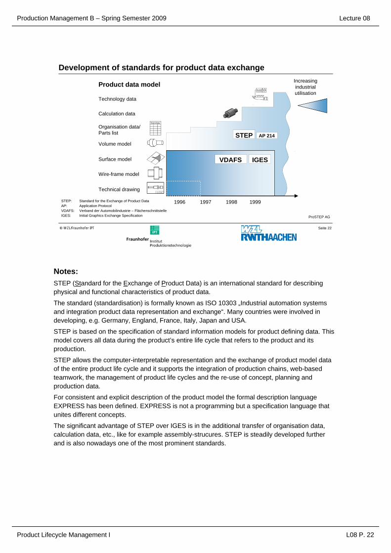
Development of standards for product data exchange
1996 1997 1998 1999
Stückliste
STEP AP 214
Welle
STEP: Standard for the Exchange of Product DataAP: Application ProtocolVDAFS: Verband der Automobilindustrie – FlächenschnittstelleIGES: Initial Graphics Exchange Specification
VDAFS IGES
ProSTEP AG
0,02
Product data model
Technology data
Calculation data
Volume model
Surface model
Wire-frame model
Technical drawing
Organisation data/Parts list
Increasingindustrialutilisation
Notes:STEP (Standard for the Exchange of Product Data) is an international standard for describing physical and functional characteristics of product data.
The standard (standardisation) is formally known as ISO 10303 „Industrial automation systems and integration product data representation and exchange“. Many countries were involved in developing, e.g. Germany, England, France, Italy, Japan and USA.
STEP is based on the specification of standard information models for product defining data. This model covers all data during the product’s entire life cycle that refers to the product and its production.
STEP allows the computer-interpretable representation and the exchange of product model data of the entire product life cycle and it supports the integration of production chains, web-based teamwork, the management of product life cycles and the re-use of concept, planning and production data.
For consistent and explicit description of the product model the formal description language EXPRESS has been defined. EXPRESS is not a programming but a specification language that unites different concepts.
The significant advantage of STEP over IGES is in the additional transfer of organisation data, calculation data, etc., like for example assembly-strucures. STEP is steadily developed further and is also nowadays one of the most prominent standards.

Production Management B – Spring Semester 2009
Product Lifecycle Management I L08 P. 23
Lecture 08
Seite 23© WZL/Fraunhofer IPT
Product data exchange with STEP
ProSTEP AG
Usage within application areas with STEP
Computer Aided Design (CAD)
Computer Aided Manufacturing (CAM)
Engineering analysis (e.g. FEA)
Process planning
Product Data Management (PDM)
…
Product data
04 Material spezifizieren DGK
05 ggf. Langläuferteile spezifizieren DGK
06 Baustruktur, Verantwortlichkeiten festlegen DGK CDM
M1 Internes Design Review durchführen DGK Abstimmungsgespräch
07 Einzelteile festlegen DGK
08 Make-or-Buy Entscheidung treffen DGK, MET
09 ggf. Laufdynamik berechnen LD
10 ggf. statisches/dynamisches Verhalten berechnen STA
M2 QFD-Methode anwenden DGK „House of Quality“
M3 Konstruktions-FMEA durchführen DGK FMEA-Formblatt
M4 Ergebnisse der Morphologie überprüfen DGK Morphologischer Kasten
11 Einzelteile grob gestalten DGK CATIA Exact Solids, Sheet Metal Designer
12 Anbindung an Drehgestell grob gestalten DGK CATIA Exact Solids, Sheet Metal Designer
M5 Informationsweitergabe und –rückführung oder Abstimmung mit Statik, Laufdynamik
DGK, STA, LD
Datenaustausch oder Abstimmungsgespräch
M6 Digital Mock Up (DMU) aufbauen DGK 4D-Navigator
M7 Internes Design Freeze durchführen DGK, STA, LD
CATIA Exact Solids, 4D-Navigator
M8 Bauteilbeanspruchung überschlägig prüfen DGK Generative Part Stress
spe zi fiz i e re n
*
*
Design Geometry Parts lists Production plans Kinematicssimulation
Quality control plans,measuring data
Manufacturing resources &method plansProduction dataNC-ProgrammingProduct-
documentationFinite Element
Analysis

Production Management B – Spring Semester 2009
Product Lifecycle Management I L08 P. 24
Lecture 08
Seite 24© WZL/Fraunhofer IPT
Possibilities of realising interfaces within the field of CAx
Man
ufac
ture
r-sp
ecifi
cA
pplic
atio
n-sp
ecifi
cN
eutra
lLinking based on a standard data format
CADPre-
processorStandard
data format(e.g. IGES)
Post-processor NC
CAD Linking-programme NC
CAD/CAM(CAD-module)
Computer-internal model
CAD/CAM(NC-module)
Linking based on an application-specific linking-programme
Linking based on a shared computer-internal model representation CAD: Computer Aided Design
CAM: Computer Aided Manufacturing
IGES: Initial GraphicsExchange Specification
NC: Numerical Control
Notes:The example of linking CAD and NC shows how data exchange between two systems with different data formats is handled:
Exchange with standard data format and implementation into the system-specific format
Exchange with an application-specific linking programme
Exchange of data by using a standard computer-internal model. That is why no formatimplementation is necessary.

Production Management B – Spring Semester 2009
Product Lifecycle Management I L08 P. 25
Lecture 08
Seite 25© WZL/Fraunhofer IPT
Problems with CAD-data exchange in IGES-formatDispatching system
Utilisation of non IGES-compliant elements and attributes (e.g. colouring)
Pre-processorIncomplete implementation of IGES-elementsFailure within IGES-format (e.g. manufacturer-designed syntax)
Post-processorIncomplete analyses of allIGES-elements
Target systemHigher mathematical accuracy than within the dispatching systemNo adequate system element for some IGES-elements
CAD System
CAxSystem
Data exchange inIGES-format
Notes:In spite of standard interface formats a data exchange is normally not exact. As shown in the picture, every other interface has similar difficulties. Within the STEP-development these error causes should be avoided.

Production Management B – Spring Semester 2009
Product Lifecycle Management I L08 P. 26
Lecture 08
Seite 26© WZL/Fraunhofer IPT
Integration of CAD and FEACAD Model: Initial solution
Min. weight
Min. parts tension
Min. deformation
Optimised calculation geometryCAD Model: optimised alternative
Reverse transformationof optimised geometry
Automatic model transformation and
integration
FEM Model
Targets of optimisation: Parameter:
Wall thickness
Form
Topology
Notes:Besides actual CAD-systems additional supplementing EDP-modules contribute to a rationalisation in design.
Special calculating-modules based on FEA (Finite Element Analysis) assist a strain-related optimisation of parts geometries.
FEA is a calculation method that divides the physical structure of an object into finite mechanical/ mathematical defined elements. These elements are linked by discreet cross points. The state of an object under load is calculated by numerical approximation procedures in stepwise transmission of state variables at cross points.
Production Management B – Spring Semester 2009
Product Lifecycle Management I L08 P. 27
Lecture 08
Seite 27© WZL/Fraunhofer IPT
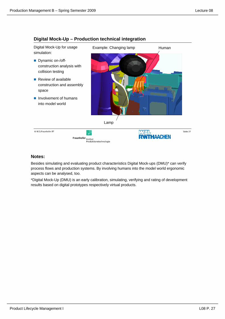
Digital Mock-Up – Production technical integrationDigital Mock-Up for usage simulation:
Dynamic on-/off-construction analysis withcollision testing
Review of available construction and assembly space
Involvement of humans into model world
Example: Changing lamp
Lamp
Human
Notes:Besides simulating and evaluating product characteristics Digital Mock-ups (DMU)* can verify process flows and production systems. By involving humans into the model world ergonomic aspects can be analysed, too.
*Digital Mock-Up (DMU) is an early calibration, simulating, verifying and rating of development results based on digital prototypes respectively virtual products.

Production Management B – Spring Semester 2009
Product Lifecycle Management I L08 P. 28
Lecture 08
Seite 28© WZL/Fraunhofer IPT
Potential of Digital Mock-Up
Development time and costs can be reduced with the help of DMU!Examples: Automotive industry up to 30% *
Aircraft industry up to 40% **
time
Trial
PMU Process
DMU process100 %
construction
DMU Check HW Check
Source:* Koytek ** US Air ForceSource: von Praun
Legend:DMU: Digital Mock-UpPMU: Physical Mock-UpHW: Hardware
time
Changing-costs
Product-quality
Costsper failure
DesignDevelopment
Process planningManufacturing Customer
Final inspection
Source: PfeiferBenchmark deficit

Production Management B – Spring Semester 2009
Product Lifecycle Management I L08 P. 29
Lecture 08
Seite 29© WZL/Fraunhofer IPT
Quantification for increase of productivity
CAD/CAM capable time share tf
Reduced time share tr = tf / R
Additional capacity tz = tf – tr
Working time reduced by CAD/CAM tmr = tm – tz
Factor of increase of productivity Cp = tm / tmr
Additional capacity tz
Reduction factor RTotal time tm
CAD/CAM capable time share tf Not influence-able by CAD/CAM
Design
Calcula
tion
Drawing
Chang
ing
Contro
lling
Seco
ndar
y
proc
essin
g
timesPr
ovidi
ng
infor
mation
Repea
ted
parts
sear
ch
Parts
list
creati
on
Notes:The calculation of the economic efficiency of CAD-systems is difficult. By considering all individual activities the total benefit based on time and costs is quantified in design.
Production Management B – Spring Semester 2009
Product Lifecycle Management I L08 P. 30
Lecture 08
Final statement:PLM comprises the management and control of the complete product data of the whole lifecycle along the enhanced logistics supply chain.
CAD is a generic term for all activities that use EDP directly or indirectly within construction and development activities.
The use of 3D CAD models allows an easy linking to NC-programming and FEM-analysis.
Digital Mock-Up (DMU) supports early simulation and check of development results based on digital prototypes resp. Virtual products.
The calculation of efficiency of CAD-systems is difficult. The overall benefit regarding time and costs in construction is quantified through the mediation of single activities.

Production Management B – Spring Semester 2009
Product Lifecycle Management I L08 P. 31
Lecture 08
Bibliography:
M. Grieves, Product Lifecycle Management: Driving the Next Generation of Lean Thinking, New York: McGraw-Hill, 2006
G. Susman, Product Life Cycle Management, Hamilton, Ont.: Society of Management Accountants of Canada, 1994
G. Hartmann, mySAP Product Lifecycle Mangement: Strategien –Technologie - Implementierung, Bonn, Galileo Press, 2004
J. Stark, Product Lifecycle Management: 21st Century Paradigm forProduct Realisation, London, Springer, 2006