Embed Size (px)
Citation preview

Faculty of Electronics, Telecommunications and
Information TechnologyGheorghe Asachi Technical University of Iasi
C www.study.tuiasi.ro www.learning.tuiasi.ro
Title of Discipline:
Computer-Aided Analysis of Electronic Circuits
Laboratory Lecture 6
Bachelor : Telecommunication Technologies and Systems
Year of Study: 2
www.etti.tuiasi.ro

C www.study.tuiasi.ro www.learning.tuiasi.ro
”Title of discipline: CAAEC
www.etti.tuiasi.ro
Computer-Aided Analysis of Electronic Circuits
Laboratory 6
PSpice DC analysis

C www.study.tuiasi.ro www.learning.tuiasi.ro
”Title of discipline: CAAEC
www.etti.tuiasi.ro
Standard analyses in PSpice
PSpice command Description
.OP (bias point) Bias point
.DC ( DC analysis) DC sweep
.TF (transfer) Small-signal DC transfer function
.SENS (sensitivity analysis) DC sensitivity
.AC ( AC analysis) Frequency response
.NOISE (noise analysis) Noise
.TRAN (transient analysis) Transient
.FOUR (Fourier analysis) Fourier components

C www.study.tuiasi.ro www.learning.tuiasi.ro
”Title of discipline: CAAEC
www.etti.tuiasi.ro
Purpose
The .OP command causes detailed information about the bias point to be printed.
General form
.OP
Comments
This command does not write output to the Probe data file. The bias point is
calculated whether or not there is a .OP command. Without the .OP command,
the only information about the bias point in the output is a list of the node
voltages.
With a .OP command the currents and power dissipation of all the voltage
sources are printed.
.OP command

C www.study.tuiasi.ro www.learning.tuiasi.ro
”Title of discipline: CAAEC
www.etti.tuiasi.ro
Using a .OP command can cause the small-signal (linearized) parameters of all the non-linear controlled
sources and all the semiconductor devices to be printed in the output file.
The .OP command controls the output for the regular bias point only.
The .TRAN command controls the output for the transient analysis bias point.
Example
V1 1 0 5
R1 1 2 100
R2 2 0 100
D1 2 0 D1N4148
.MODEL D1N4148 D(Is=2.682n N=1.836 Rs=.5664 Ikf=44.17m Xti=3 Eg=1.11 Cjo=4p M=03333 Vj=.5
+Isr-1.565n Nr=2 Bv=100 Ibv=100u Tt=11.54n)
.OP
.END
.OP command

C www.study.tuiasi.ro www.learning.tuiasi.ro
”Title of discipline: CAAEC
www.etti.tuiasi.ro
The results of .OP command are printed in the output file, as below:
SMALL SIGNAL BIAS SOLUTION TEMPERATURE = 27.000 DEG C
NODE VOLTAGE NODE VOLTAGE
(1) 5.0000 (2) .8206
VOLTAGE SOURCE CURRENTS
NAME CURRENT
V1 -9.179E-02
TOTAL POWER DISSIPATION 4.59E-01 WATTS
.OP command
C www.study.tuiasi.ro www.learning.tuiasi.ro
”Title of discipline: CAAEC
www.etti.tuiasi.ro
Purpose
The .NODESET command helps calculate the bias point by providing an initial best guess
for some node voltages. Some or all of the circuit’s node voltages can be given the
initial guess, and in addition, the voltage between two nodes can be specified.
General Form
.NODESET < V(<node> [,<node>])=<value> >*
Examples
.NODESET V(5)=2.6V V(12)=-1.7V I(L1)=1uA
.NODESET V(IN1,IN2)=3mV V(9,3)=7.25V
.NODESET command

C www.study.tuiasi.ro www.learning.tuiasi.ro
”Title of discipline: CAAEC
www.etti.tuiasi.ro
This command is effective for the bias point (both small-signal and transient bias points)
and for the first step of the DC sweep. It has no effect during the rest of the DC sweep,
nor during a transient analysis.
Unlike the .IC command, .NODESET provides only an initial guess for some initial values.
It does not clamp those nodes to the specified voltages. However, by providing an
initial guess, .NODESET can be used to “break the tie” in, for instance, a flip-flop, and
make it come up in a required state.
If both the .IC command and .NODESET command are present, the .NODESET command
is ignored for the bias point calculations (.IC overrides .NODESET).
.NODESET command
C www.study.tuiasi.ro www.learning.tuiasi.ro
”Title of discipline: CAAEC
www.etti.tuiasi.ro
Purpose
The .DC command performs a linear, logarithmic, or nested DC sweep analysis on the
circuit. The DC sweep analysis calculates the circuit’s bias point over a range of values for
<sweep variable name>.
General Forms
.DC <linear sweep type> <sweep variable name>
+ <start value> <end value> <increment value> [nested sweep specification]
.DC <logarithmic sweep type> <sweep variable name>
+ <start value> <end value> <points value> [nested sweep specification]
.DC <sweep variable name> LIST <value>* [nested sweep specification]
.DC command

C www.study.tuiasi.ro www.learning.tuiasi.ro
”Title of discipline: CAAEC
www.etti.tuiasi.ro
Sweep type - The sweep can be linear, logarithmic, or a list of values.
.DC command
Parameter Description Meaning
LIN linear sweep The sweep variable is swept linearly from the
starting to the ending value.
OCT sweep by
octaves
Sweep by octaves. The sweep variable is swept
logarithmically by octaves.
DEC sweep by
decades
Sweep by decades. The sweep variable is swept
logarithmically by decades.
LIST List of values Use a list of values.

C www.study.tuiasi.ro www.learning.tuiasi.ro
”Title of discipline: CAAEC
www.etti.tuiasi.ro
General form
.DC [LIN] <sweep variable name>
+ <start value> <end value> <increment value>
+ [nested sweep specification]
Examples
.DC VIN -.25 .25 .05
.DC LIN I2 5mA -2mA 0.1mA
.DC VCE 0V 10V .5V IB 0mA 1mA 50uA
.DC RES RMOD(R) 0.9 1.1 .001
Linear Sweep

C www.study.tuiasi.ro www.learning.tuiasi.ro
”Title of discipline: CAAEC
www.etti.tuiasi.ro
General form
.DC [LIN] <sweep variable name> <start value> <end value> <increment value>
+ [nested sweep specification]
Examples
.DC VIN -.25 .25 .05
.DC LIN I2 5mA -2mA 0.1mA
.DC VCE 0V 10V .5V IB 0mA 1mA 50uA
.DC RES RMOD(R) 0.9 1.1 .001
Arguments and options
<start value> Can be greater or less than <end value>: that is, the sweep can go in either direction.
<increment value> The step size. This value must be greater than zero.
Linear Sweep

C www.study.tuiasi.ro www.learning.tuiasi.ro
”Title of discipline: CAAEC
www.etti.tuiasi.ro
General form
.DC <logarithmic sweep type> <sweep variable name> <start value> <end value> <points value>
+ [nested sweep specification]
Examples
.DC DEC NPN QFAST(IS) 1E-18 1E-14 5
Arguments and options
<logarithmic sweep type> Must be specified as either DEC (to sweep by decades) or OCT (to sweep
by octaves).
<start value> Must be positive and less than <end value>.
<points value> The number of steps per octave or per decade in the sweep. This value must be an
integer.
Logarithmic Sweep

C www.study.tuiasi.ro www.learning.tuiasi.ro
”Title of discipline: CAAEC
www.etti.tuiasi.ro
General form
.DC <sweep variable name> LIST <value>* [nested sweep specification]
Examples
.DC TEMP LIST 0 20 27 50 80 100 PARAM Vsupply 7.5 15 .5
Arguments and options
<sweep variable name> After the DC sweep is finished, the value
associated with
<sweep variable name> is set back to the value it had before the
sweep started. The following items can be used as sweep variables in a
DC sweep:
Nested Sweep
C www.study.tuiasi.ro www.learning.tuiasi.ro
”Title of discipline: CAAEC
www.etti.tuiasi.ro
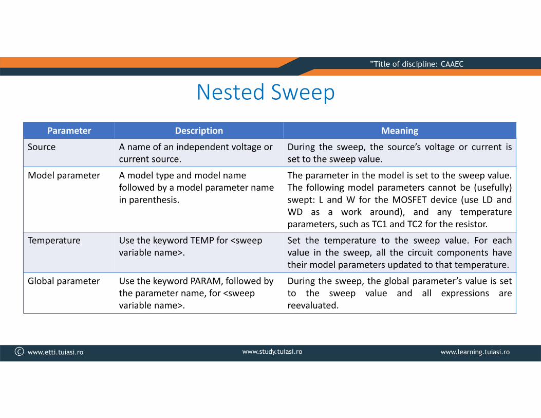
Nested Sweep
Parameter Description Meaning
Source A name of an independent voltage or
current source.
During the sweep, the source’s voltage or current is
set to the sweep value.
Model parameter A model type and model name
followed by a model parameter name
in parenthesis.
The parameter in the model is set to the sweep value.
The following model parameters cannot be (usefully)
swept: L and W for the MOSFET device (use LD and
WD as a work around), and any temperature
parameters, such as TC1 and TC2 for the resistor.
Temperature Use the keyword TEMP for <sweep
variable name>.
Set the temperature to the sweep value. For each
value in the sweep, all the circuit components have
their model parameters updated to that temperature.
Global parameter Use the keyword PARAM, followed by
the parameter name, for <sweep
variable name>.
During the sweep, the global parameter’s value is set
to the sweep value and all expressions are
reevaluated.

C www.study.tuiasi.ro www.learning.tuiasi.ro
”Title of discipline: CAAEC
www.etti.tuiasi.ro
Nested Sweep
Comments
For a nested sweep, a second sweep variable, sweep type, start, end,
and increment values can be placed after the first sweep. In the nested
sweep example, the first sweep is the inner loop: the entire first sweep
is performed for each value of the second sweep.
When using a list of values, there are no start and end values. Instead,
the numbers that follow the keyword LIST are the values that the sweep
variable is set to.
C www.study.tuiasi.ro www.learning.tuiasi.ro
”Title of discipline: CAAEC
www.etti.tuiasi.ro
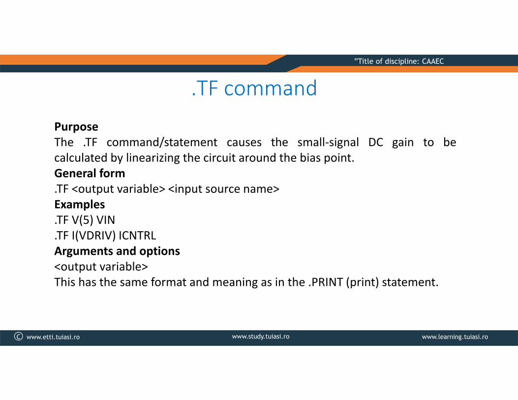
.TF command
Purpose
The .TF command/statement causes the small-signal DC gain to be
calculated by linearizing the circuit around the bias point.
General form
.TF <output variable> <input source name>
Examples
.TF V(5) VIN
.TF I(VDRIV) ICNTRL
Arguments and options
<output variable>
This has the same format and meaning as in the .PRINT (print) statement.

C www.study.tuiasi.ro www.learning.tuiasi.ro
”Title of discipline: CAAEC
www.etti.tuiasi.ro
.TF command
Comments
The gain from <input source name> to <output variable> and the input
and output resistances are evaluated and written to the output file. This
output does not require a .PRINT (print), .PLOT (plot), or .PROBE (Probe)
statement. When <output variable> is a current, it is restricted to be the
current through a voltage source.
Note: The results of the .TF command are only available in the output file.
They cannot be viewed in Probe.

C www.study.tuiasi.ro www.learning.tuiasi.ro
”Title of discipline: CAAEC
www.etti.tuiasi.ro
.SENS command (sensitivity analysis)Purpose
The .SENS command performs a DC sensitivity analysis.
General form .SENS <output variable>*
Examples
.SENS V(9) V(4,3) V(17) I(VCC)
Arguments and options
<output variable>
Same format and meaning as in the .PRINT command for DC and transient
analyses. However, when <output variable> is a current, it is restricted to be the
current through a voltage source.
C www.study.tuiasi.ro www.learning.tuiasi.ro
”Title of discipline: CAAEC
www.etti.tuiasi.ro
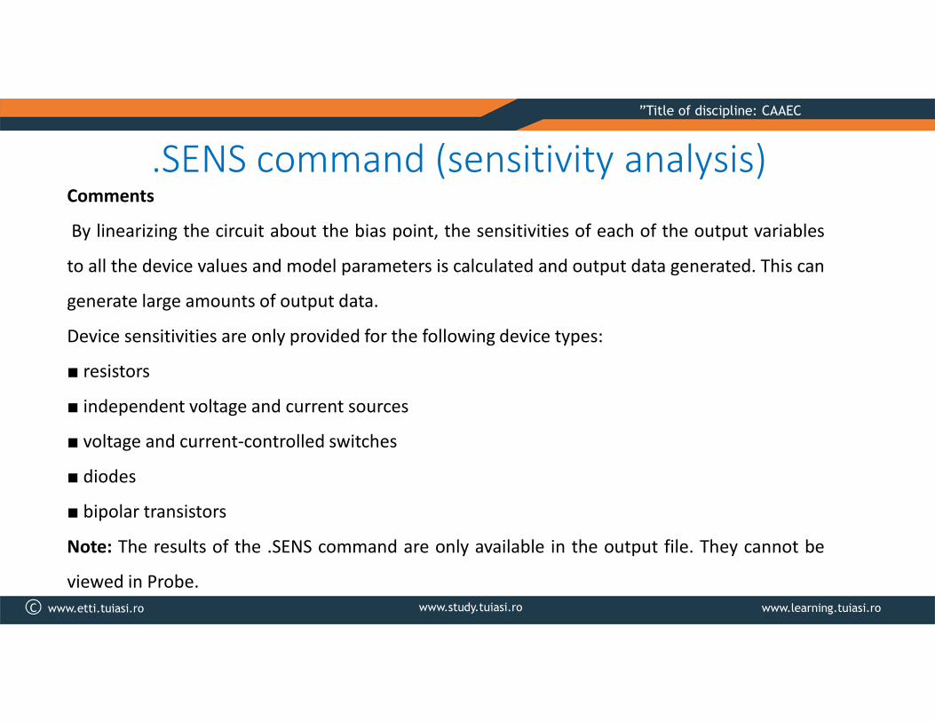
.SENS command (sensitivity analysis)Comments
By linearizing the circuit about the bias point, the sensitivities of each of the output variables
to all the device values and model parameters is calculated and output data generated. This can
generate large amounts of output data.
Device sensitivities are only provided for the following device types:
■ resistors
■ independent voltage and current sources
■ voltage and current-controlled switches
■ diodes
■ bipolar transistors
Note: The results of the .SENS command are only available in the output file. They cannot be
viewed in Probe.

C www.study.tuiasi.ro www.learning.tuiasi.ro
”Title of discipline: CAAEC
www.etti.tuiasi.ro
Application 1
Applications
Activities:
•Describe the circuit shown in Figure1(a)
into the SPICE circuit file (.cir). The
nonlinear resistor RN has the I-V
characteristic in the Figure 1(b). Model the
nonlinear resistor RN by a Voltage-controlled
current source using TABLE variant.
•Explain the necessity of the resistor R1 =
100Mohms from simulation point of view.

C www.study.tuiasi.ro www.learning.tuiasi.ro
”Title of discipline: CAAEC
www.etti.tuiasi.ro
Application 1
Applications
Activities:
•The circuit described in the Figure1(a) has 3 bias points (A, B, and C). Determine by
simulation the value of V(1). Which one from the three points is determined by the
simulator?
• Use the .NODESET command to set the starting value of V(1) for bias point calculation
as in the below table and fill out the results. Explain the results..NODESET V(1) = 0.5 2 2.7 3.5 4.8 6
Bias point V(1)
determined by the
simulator
The corresponding
point in the Figure 1b

C www.study.tuiasi.ro www.learning.tuiasi.ro
”Title of discipline: CAAEC
www.etti.tuiasi.ro
ApplicationsApplication 2
Activities: 1. Describe into the SPICE circuit
file (.cir) the circuit shown in following figure:
The model type for the Q1 and Q2 transistors
is BC107A. The PSpice description of these
transistors is as below:
Q1 2 1 4 BC107A
Q2 3 0 4 BC107A
.LIB NOM.LIB
The BC107A model is defined in the library as:
.MODEL BC107A NPN(model parameters).
The .LIB command defines the name of the
library file

C www.study.tuiasi.ro www.learning.tuiasi.ro
”Title of discipline: CAAEC
www.etti.tuiasi.ro
ApplicationsApplication 2
Activities:
2. For the mentioned circuit do the following:
a) Determine the bias point. Determine the values for the voltages in the circuit’s nodes, IC(Q1) and
IC(Q2) current values and the power absorbed from the power supply source.
b) Perform a DC analysis in which Vin is swept in the range (-1V, +1V). Choose a proper incremental value
to have about 100 calculation points. Visualize in Probe the following:
- Output voltage V(3). What is the meaning of the graph?
- Collector currents of Q1 and Q2: IC(Q1), IC(Q2)

C www.study.tuiasi.ro www.learning.tuiasi.ro
”Title of discipline: CAAEC
www.etti.tuiasi.ro
ApplicationsApplication 2
Activities:
c) Perform a DC analysis in which the value of R3 resistor is swept in the range (1K , 5K). Hint: use a global
parameter for the value of R3 resistor. Visualize in Probe the nodal voltage V(4).
d) Perform a DC analysis in which the model parameter BF from the model BC107A of the NPN bipolar
transistor is swept in the range (50, 150). Visualize in Probe the output voltage.
e) Perform a DC analysis in which the temperature is swept in the range (-25°C la +75°C ). Visualize in
Probe the output voltage. How is the range of the output voltage?
f) Use .TF command to obtain the small signal DC transfer function. Find the results in the output file.
g) Perform the sensitivity analysis (.SENS command) for the output voltage V(3). Find the results in the
output file.