Embed Size (px)
Citation preview

Electronics Design LaboratoryLecture #9
ECEN 2270 1Electronics Design Laboratory

Notes• Finishing Lab 4 this week• Demo requires position control using interrupts and two actions
• Rotate a given angle• Move forward a given distance
• Tuesday: finish Lab 4 Part B• Thursday: Lab 4 demo with a battery‐pack powered robot
– Stop, wait for the switch to be in the ON position– Wait 1 second– Move forward 2‐feet– 180o clockwise rotation of the robot– Move forward 2‐feet– 180o counter clockwise rotation of the robotAccuracy: the robot should come back to the starting position
• Next week: skip Lab 5, start Lab 6 (Project)
Electronics Design Laboratory 2ECEN 2270

Speed and Position Control
Electronics Design Laboratory 3ECEN 2270
Encoder
On/Off
Vref
Inputs Outputs
10VDC 5VDC
Need a relation between our control variables (Vref and On/Off) and our output variable (position). Two approaches are frequently used.
• Speed Control– Relies on the fact the distance = speed * time
– Uses no external inputs, simple to implement, and inaccurate
• Position Control– Directly measures motor position to set robot position
– Needs external inputs, more complicated, but more accurate
In the real world… pick the approach which fits your needs.

Position Control based on Speed Control (Theory)
Electronics Design Laboratory 4ECEN 2270
timespeeddistance
ω
r
distancesenseK ω
Vref
Vs
Input Output
senseref KVIn steady state… r2turn
distance
timetime22
distance
sense
ref
KrV
r
time180distance
2360rotation
sensew
ref
w KrrV
r
Input
time

Electronics Design Laboratory 5ECEN 2270
Position Control based on Speed Control (μC code example)
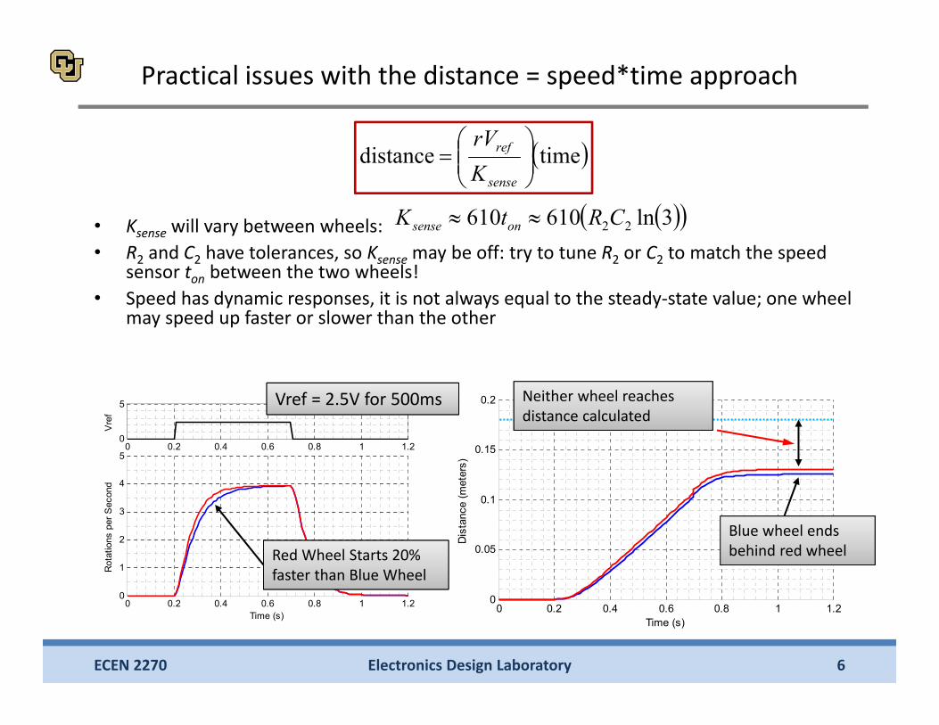
• Example: Ksense = 0.46, want to go forward 18cm.– Decide that we want to go forward at half speed, so Vref = 2.5– Using previous equations, travel time = 500ms
0 0.2 0.4 0.6 0.8 1 1.20
0.05
0.1
0.15
0.2
Time (s)
Dis
tanc
e (m
eter
s)
Practical issues with the distance = speed*time approach
• Ksense will vary between wheels:• R2 and C2 have tolerances, so Ksense may be off: try to tune R2 or C2 to match the speed
sensor ton between the two wheels!• Speed has dynamic responses, it is not always equal to the steady‐state value; one wheel
may speed up faster or slower than the other
Electronics Design Laboratory 6ECEN 2270
timedistance
sense
ref
KrV
3ln610610 22CRtK onsense
0 0.2 0.4 0.6 0.8 1 1.20
5
Vre
f
0 0.2 0.4 0.6 0.8 1 1.20
1
2
3
4
5
Time (s)
Rot
atio
ns p
er S
econ
d
Red Wheel Starts 20% faster than Blue Wheel
Vref = 2.5V for 500ms
Blue wheel ends behind red wheel
Neither wheel reaches distance calculated

Better: position control based on counting encoder pulses
Electronics Design Laboratory 7ECEN 2270
ω
r
distanceenc
Vref
Output
Inputenc
distancepulses
distanceturns
turnrotations
rotationpulses
wheelencoder gear-boxinput to output
relation!
distance216412 encNπr
384 distance πrNenc ≈ 0.53 mm
pulse

Encoder based Position Control
Electronics Design Laboratory 8ECEN 2270
ω
r
enc
Vref
Output
Inputenc
384 distance πrNenc
• Each encoder pulse represents a fraction of a wheel turn• Distance read directly, without guessing speed/distance relation
• This is better… but how do we read encoder pulses?– The simple approach is called ‘polling’, or ‘busy‐wait’– The better approach uses ‘event‐driven’ programming using an interrupt
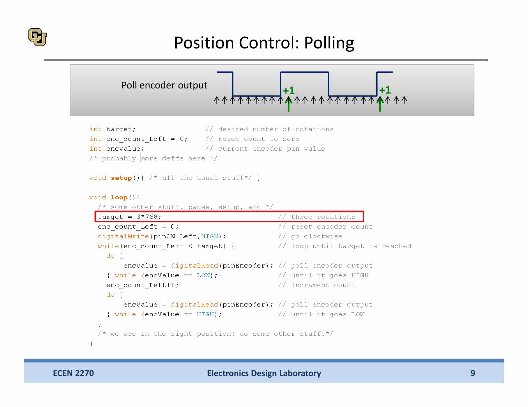
Counting rising edges of encoder to tell distance +0.53mm +0.53mm
Electronics Design Laboratory 9ECEN 2270
+1 +1Poll encoder output
Position Control: Polling
Electronics Design Laboratory 10ECEN 2270
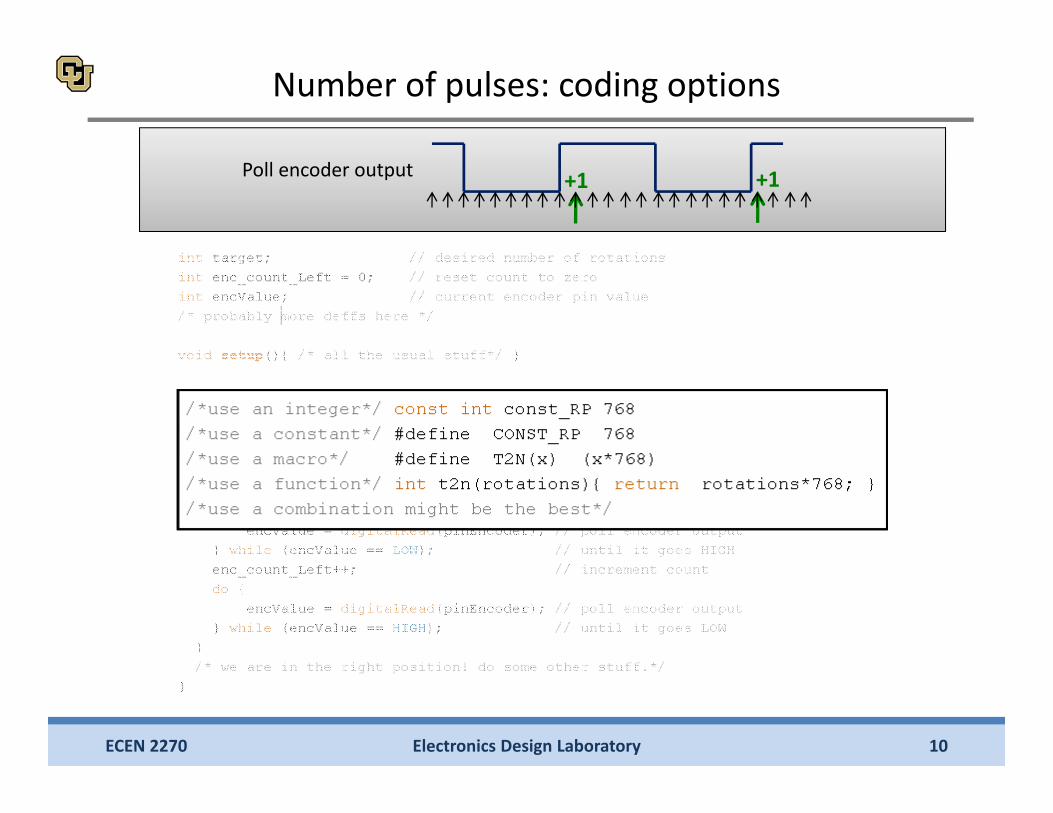
+1 +1Poll encoder output
Number of pulses: coding options

Electronics Design Laboratory 11ECEN 2270
Encoder outputC executes other tasks …
C executes other tasks …
C executes other tasks …
Increment
Position Control – Polling vs. Event Driven
Increment
Encoder output
Increment Increment
Encoder Output
Encoder Output
μC time
μC time
C waiting for transition…
C waiting for transition…
C waiting for transition…
Polling / Busy‐Wait
• Wastes μC time• Doesn’t allow other
tasks to execute!
Event Driven
• Allows other tasks to execute!
• Want our program to do useful stuff between encoder pulses• Ideally, when a rising encoder pulse is seen, our microcontroller with switch tasks to a
small, fast function to increment our encoder counter• The small function is called an ‘interrupt service routine’, and handling inputs this way
is called ‘event‐driven input/output’ programming

Electronics Design Laboratory 12ECEN 2270
Position Control – Event Driven
loop()
ISR_count( )
• Loop runs between encoder pulses• When a rising edge is detected, we
quickly run ISR_count• When needed, loop can read the
value of enc_count• No waiting required! Event‐driven
input/output is better in this case
Encoder outputEncoder Output
μC time
Event Driven
Allows other tasks to execute!
loop()loop()
ISR_count( )

attachInterrupt pins on Arduino Uno: 0=pin2, 1=pin3
Electronics Design Laboratory 13ECEN 2270
ATmega3
28P 8‐bit u
C
10VGND5V
• Inputs from robot: On/Off (for future use) and Encoder Pulses (for future use)• Outputs to robot: Stop/Go controls (2 per wheel) Speed reference (1 or 2 total)• Voltages: 5VDC for speed sensing circuits and 10VDC for Motors/Encoders
ENCODER_L( 2)ENCODER_R( 3)
ON/OFF( 6)CW_L( 7)CC_L( 8)REF_L( 9)
REF_R(10)CW_R(11)CC_R(12)
LED(13)
Input from bench supply or battery
Output used to supply +5V circuitry (Labs 2 and 3)
Interrupt 0 (pin 2):
Interrupt 1: (pin 3)

Finer positioning details: Setting Speed Reference
Electronics Design Laboratory 14ECEN 2270
Motor System
384r
TargetNenc Control
CodeVref 2
21
1
oo
ss
ωDesired Position
EncoderActualNenc
Counter ISR
MicrocontrollerInputs
Desired Position
Robot Speed
Vref
Actual Position
Start Action
Encoder Count Reached
Robot Stops Moving
Momentum keeps robot moving
Simple approach leads to overshoot…
time

Electronics Design Laboratory 15ECEN 2270
Desired Position
Robot Speed
Vref
Actual Position
Start Action
Encoder Count Reached
Robot Stops Moving
time
• Lowering Vref can reduce but not remove overshoot.• Either:
– Offset the target Nenc because you know you will overshoot, or– Be smarter about setting Vref
Example:
endstartref
encencMaxend
encMaxstart
refref
refref
refref
VVMinV
NNVMinV
NVMinV
,
,
,actualtarget
actual
VrefMax
Finer positioning details: setting speed reference as a function of distance traveled

Lab 4 Demo• Show how the robot powered from 2 battery packs in series (approximately 10 V)
can accomplish the specified Part B.2 positioning task:– Stop, wait for the switch to be in the ON position– Wait 1 second– Move forward 2‐feet– 180o clockwise rotation of the robot– Move forward 2‐feet– 180o counter‐clockwise rotation of the robotAccuracy: the robot should come back to the starting position
• Show your position control program• Show complete speed control circuit, and complete LTspice diagram of your speed
control circuit• Answer questions related to your position control code and speed control circuit
Electronics Design Laboratory 16ECEN 2270
This Lab includes an extra credit opportunity: see next page

Electronics Design Laboratory 17ECEN 2270
Lab 4, B.4 Extra CreditThe groups whose robot accurately completes the following tasks will be eligible for extra credit
• Robots will start centered on a floor intersection facing ‘north’
• From the starting position, robot must perform the following moves, as shown on the diagram:• Move forward one square ‘north’• Turn 90o CC • Move forward two squares ‘west’• Turn 90o CW• Move forward one square ‘north’• Turn 90o CW• Move forward one square ‘east’• Turn 90o CW• Move forward two squares ‘south’• Turn 90o CC• Move forward one square ‘east’• Turn 90o CC and stop
• At the end, the robot should ideally be in the starting position.
Accuracy requirements:• Robot platform must always cover a portion of the floor line along the route shown in
the diagram• In the end position, both wheel axis tips must be within +/‐ 5cm (+/‐ 2”) of the southern
horizontal floor line, and the caster wheel must be within +/‐ 5cm (+/‐ 2”) of the eastern vertical floor line
N
E
S
W
START and END
Caster wheel
39.5” = 100 cm

Appendix
Some basic C topics: word length, interrupts, serial communication
ECEN 2830 Electronics Design Laboratory 18

• What is the ‘word length’ of a processor?– This is the bit‐size that the processors instruction set operates
on, and generally the size of the processors data bus and ALUs– This is sometimes referred to as the ‘natural’ unit that the
processor uses– The Arduino UNO uses an 8‐bit processor,
• with an 8‐bit instruction word size• with an 8‐bit data word size (data bus is 8‐bits)• with a 16‐bit address word length…
– Not an exact term. Used in many ways. Confusing, and needs a modifier to make any sense
– Old processors (pre 1965) used 6‐bit word length. First 8‐bit mainframe was the ‘System/360’
• How does serial work?– Many standards (I2C, RS‐232, ‘something you made up’, etc..)– Lets go over simplified RS‐232
Electronics Design Laboratory 19ECEN 2830
Answers
Electronics Design Laboratory 20ECEN 2830
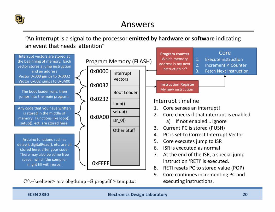
Answers“An interrupt is a signal to the processor emitted by hardware or software indicating an event that needs attention”
0xFFFF
Program Memory (FLASH)
0x0000
0x0032
Interrupt Vectors
Boot Loader
loop()0x0232
setup()
Other Stuff
isr_0()0x0A00
C:\~\seltzer> arv-obgdump –S prog.elf > temp.txt
Interrupt vectors are stored at the beginning of memory. Each vector stores a jump instruction
and an addressVector 0x000 jumps to 0x0032Vector 0x002 jumps to 0x0A00
The boot loader runs, then jumps into the main program.
Any code that you have written is stored in the middle of
memory. Functions like loop(), setup(), ect. are stored here.
Arduino functions such as delay(), digitalRead(), etc. are all stored here, after your code. There may also be some free space, which the compiler
might fill with zeros.
Program counterWhich memory
address is my next instruction at?
Instruction RegisterMy new instruction!
Core1. Execute instruction2. Increment P. Counter3. Fetch Next Instruction
Interrupt timeline1. Core senses an interrupt!2. Core checks if that interrupt is enabled
a) If not enabled… ignore3. Current PC is stored (PUSH)4. PC is set to Correct Interrupt Vector 5. Core executes jump to ISR6. ISR is executed as normal7. At the end of the ISR, a special jump
instruction ‘RETI’ is executed.8. RETI resets PC to stored value (POP)9. Core continues incrementing PC and
executing instructions.

• Two wires, a transmit (Tx) and a receive (Rx)• Each wire has two states, High and Low• A device will read on its receive line (digital in), and transmit on its transmit line (digital out)
• Say device A wants to send the character ‘a’ to device B
Electronics Design Laboratory 21ECEN 2830
Serial Communication
Device A Device B
Tx
TxRx
Rx
GND GND
VDC VDC

• In ASCII, the character ‘a’ is 0x61 = 0b01100001• We can send this one bit at a time
– A ‘time series’ of bits. One bit every time step• We need to let device B know we are sending a character, so we add a start bit,
0b1. We also need to agree on how fast things will be sent. Lets choose 1bit/ms• We also need to let device B know when we are done, so we add a stop bit, 0b0• Our final series of bits is ‘1011000010
Electronics Design Laboratory 22ECEN 2830
Serial Communication
ASCII ‘a’Start Stop
Device A
Device B
Tx
TxRx
Rx
GND
GND

• Device B now needs to read the value off of the line• This is easiest to do with a shift register (Hardware implementation)
– Shift registers can converter serial data (time series) to parallel data
• We can implement this in code as well
Electronics Design Laboratory 23ECEN 2830
Serial Communication
Device A Tx
TxRx
Rx
GND GND
D Q
CLK
Rx D Q D Q D Q4‐bit shift register
b4 b3 b2 b1
Device B