Embed Size (px)
Citation preview

Laboratory Vacuum Systems
Please read and save these instructions. Read carefully before attempting to assemble, install, operate or maintain the product described. Protect yourself and others by observing all safety information. Failure to comply with instructions could result in personal injury and/or property damage! Retain instructions for future reference.
Description
Powerex • 150 Production Drive • Harrison, OH 45030 • USAP 1.888.769.7979 • F 513.367.3125 • www.powerexinc.com
IN592202AV • 02/2017Page 1 of 13
GeneralPowerex Laboratory Vacuum Systems are designed to provide
a vacuum source for laboratories and other operations requiring a reliable, proven vacuum producer. The systems include electric motor driven vacuum pumps, of either oil less or lubricated vane construction, particle filtration, vacuum receivers, piping and controls. Various options are available to make the system suit your needs, including electric or pneumatic assisted auto-purge.
The lubricated vane compressors are factory filled with full synthetic paupalphaelefin (PAO) oil for wear resistance, sealing and cooling. The full synthetic oil is selected to give long service in most applications. Oil condition and filter condition should be monitored and action taken as appropriate based on whatever conditions are encountered during service.
Oil less vacuum pumps are claw type sets, with synchronizing gearboxes utilizing synthetic gear oil for long life and reliability.
The system vacuum receiver dampens pulsations and helps even out rapid transients in vacuum demand. It is not intended to act as a liquid separator or knock out. Receiver manual or auto drains are intended for use when incidental liquid accumulation occurs in the receiver. Separate liquid separators are available as an option and if liquid enters the pumps during service they will be damaged.
All of the controls have automatic pump alteration and minimum run timers so that usage is equalized on multi pump systems and to prevent motor overload and damage from too frequent starting. Auto purge controls are available as an option for those processes requiring a fresh air flush before shutting down the off load pumps. The minimum run and auto purge functions are combined in the control as appropriate.
Specifications
Product Laboratory Vacuum Systems
Operating Voltages 208V, 230V, 460V
Control Panel UL508A
Motor TEFC Electric Motor
Tank ASME Rated for 200 psi MAWP
Drive Direct
Tank Sizes 60 Gallon to 200 Gallon
Performance See Cut Sheet

Laboratory Vacuum Systems
Powerex • 150 Production Drive • Harrison, OH 45030 • USAP 1.888.769.7979 • F 513.367.3125 • www.powerexinc.com
IN592202AV • 02/2017Page 2 of 13
ComponentsVacuum Pumps
Powerex laboratory vacuum systems use electric motor driven lubricated rotary vane or claw type pumps to create vacuum for the removal of unwanted fluids and gases. The pumps remove the gases and exhaust them to atmosphere through the exhaust piping system.
Liquids must not be allowed to enter the pumps. Appropriate liquid separation must be completed before gas and liquid mixtures read the Powerex vacuum system. Liquid knock out accessories are available for installation ahead of the Powerex vacuum system. Liquids will damage the vacuum pumps.
Systems consist of multiple vacuum pumps that are automatically controlled and alternated to equalize usage and wear. The vane type vacuum pumps use full synthetic oil for lubrication, cooling and sealing. The oil is automatically circulated through the pumps and captured in the exhaust filters for reuse. Follow the recommended oil and oil filter change guidelines in the pump manual. If the oil turns dark rapidly or exhibits any other sudden change, refer to the pump manual for appropriate action.
For claw type pumps, monitor the level of the oil in the gearbox and add or renew it as specified in the pump manual.
The motors are mated to the pumps, driving through a flexible coupling element. Some models include cooling fans on the coupling drive hubs and some have separate cooling fans. Follow the pump manual guidelines for coupling, fan and cooler care and maintenance.
The vacuum pump-motor assemblies are mounted on rubber isolation feet. Do not modify or remove the feet.
ControlsThe controls on the Powerex Laboratory Vacuum System do not
include a service disconnect and circuit protection for the supply circuit. Selection and installation of these items must be provided in compliance to local and national codes in accordance with each facility’s need. The disconnects and protection devices in the Powerex control system are for the motor branch circuits, accessory supply circuits and for the control circuit only.
Systems are available with either basic controls or advanced PXMI touch screen controls. In either case, the systems utilize a programmable logic controller (PLC) to operate the number of pump motors required to meet demand in response to vacuum level as detected by the vacuum transducer or pressure switches. The PLC automatically alternates the lead designation and brings on lag pumps as needed, equalizing run time on the sets in the system.
Lead alternation is 24 hours, unless the minimum run timer is engaged, in which case the run cycle is finished before the alternation occurs. The controls automatically provide minimum run timer functions for the vacuum pump motors, so that short on-off cycles and frequent starting are prevented. The control panel includes Hand-Off-Auto selector switches for each pump so that a pump can be held on (or off). This can be useful if maintenance or diagnostic procedures are being performed. Hour meters show the actual running hours or each pump-motor set to facilitate maintenance.
PXMI controls allow the vacuum set points to be adjusted through the menus on the screen. Systems with basic controls using mechanical vacuum switches can be adjusted by carefully turning the adjustment ring on the switch body. Incorrect adjustment will result in erratic control function.
The controls have a transformer to provide operating voltage. The transformer is sized for the loads imposed by the Powerex factory controls and should not be utilized for any other purpose. PXMI control panels (optional) utilize a back up transformer with a reserve transformer in use alarm.
Local alarms are provided for low vacuum alarm and general fault alarm. The general fault alarm includes the reserve transformer in use, motor overload and high temperature alarm. The wiring connection point for the alarms is on the terminal strip in the control panel box, with good conditions being contacts closed. (If a wire connection is lost, the result is an alarm.)
All control platforms feature an isolation valve on the vacuum line for vacuum sensors. Close this valve to prevent damage to the vacuum
A SEPARATE SAFETY BOOKLET IS PROVIDED ALONG WITH THIS MANUAL. READ AND UNDERSTAND THE SAFETY BOOKLET. This manual contains information that is very important to know and understand. This information is provided for SAFETY and to PREVENT EQUIPMENT PROBLEMS. To help recognize this information, observe the following symbols. MAKE SURE EVERYONE OPERATING OR SERVICING THE COMPRESSOR READS AND UNDERSTANDS ALL THE INFORMATION PROVIDED.
Warning indicates a potentially hazardous situation which, if not avoided, COULD result in
death or serious injury.
Caution indicates a potentially hazardous situation which, if not avoided, MAY result in minor or
moderate injury.
Notice indicates important information, that if not followed, may cause damage to equipment.
NOTE: Note indicates information that requires special attention.
Safety Guidelines
Danger indicates an imminently hazardous situation which, if not avoided, WILL result in
death or serious injury.
Do not operate unit if damaged during shipping, handling or use. Damage may result in bursting
and cause injury or property damage.
Immediately upon receipt of the vacuum system, inspect for any damage which may have occurred during shipment. Repair or replace damaged items before use. The name-plate should be checked to verify the correct model and voltage.
Unpacking
Laboratory Vacuum Systems
Powerex • 150 Production Drive • Harrison, OH 45030 • USAP 1.888.769.7979 • F 513.367.3125 • www.powerexinc.com
IN592202AV • 02/2017Page 3 of 13
Factory installed receiver is used for vacuum capacity only and is NOT a collection receiver. Never drill holes in, or perform any welding on receiver tanks (unless
qualified by ASME to do so) or use them beyond the rated pressure settings. Never mount other machinery or equipment on receivers.
sensing equipment during any pressure testing of the vacuum lines.
Filters, Check Valves, & Isolation ValvesEach vacuum pump has an intake filter that will remove solid
particles from the gas stream. The element is inside the canister style housing and is accessible by releasing the spring clamps and removing the cover. In most cases it will be necessary to vent air into the filter canister to relieve the vacuum before the cover can be removed. The canister cover or the canister body main pipe thread fitting has a small pipe plug for that purpose. Use a hex key wrench to remove the plug, relieve the vacuum and then replace the plug. Filter elements have pleated polyester elements designed to fit the canister. Use factory replacement elements to assure a good fit and avoid leak paths that could allow damaging particles to enter the pumps. When replacing elements be careful to avoid dislodging accumulated debris that can then be sucked into the pump and cause damage. Clean the inside of the canister carefully.
Each vacuum pump is equipped with a check valve between the intake filter and the pump inlet. The check valve assures that when a pump is off, air does not flow backwards through the pump and into the system.
The manually actuated quarter turn isolation valve is ahead of the intake filter, between it and the system. It must be closed when isolating a pump to perform some maintenance actions or to perform system diagnostics. The system piping will include a union assembly after the isolation valve to allow a pump to be removed without disassembling the remainder of the piping system.
Optional Auto Purge SystemPXMI Control Panels Only. Powerex Laboratory Vacuum systems
can be ordered with Auto Purge valves. Pneumatically operated, electrically controlled or all electric valves are available. If the pneumatically operated valves are selected, an external source or air pressure is required. The clean, dry air should have a minimum pressure of 80 psig.
The auto purge system operates so that fresh room air is allowed to flow through the pumps for 15 minutes after they are no longer needed to provide vacuum. The auto purge run time is combined with the minimum run timer. This prevents condensation or accumulation of unwanted vapors or gases in the pump when it is turned off. The auto purge intake valve has a particulate filter, vacuum gauge and small valve upstream. The valve is set to maintain 15 inches of intake vacuum to avoid overloading the pump motor yet still providing sufficient fresh air to flush the pump. A switch to allow manual purge valve operation in the event of control malfunction is included in the control panel.
High Temperature SwitchesIn some cases it can be useful to monitor the oil sump temperature.
Powerex offers factory installed temperature switches that work with the PLC control that will shut off the pump motor if the recommended oil temperature is exceeded. The control will display an alarm status and log.
Vacuum ReceiverThe Powerex system includes a lined vacuum receiver with sight
gauge to allow storage of some vacuum. The receiver will help smooth out pulsations in vacuum levels from pumps starting and stopping and from variable demand loads on the system. The receiver should not be relied on to act as a liquid removal device. It is equipped with a manual or optional auto drain to allow periodic removal of any liquid that has accumulated during normal operation. Do not modify the receiver or use it for any other purpose than its intended use.
Frames or Tankmount StructurePowerex designed the system to bear the weight and stress of the
vacuum pumps, controls, and receiver tank. When lifting the system, use the designated fork lift slots or rig straps to lift the main system skid. Do not attempt to lift the system using individual component lifting hooks and eyes.
Piping may need to be supported to avoid damaging the supplied flex connectors for intake and exhaust.
Operation at High AltitudesVacuum pumps are sensitive to reduced atmospheric pressure
encountered as altitude increases. Powerex will adjust the operating set points (on basic control panels) to compensate for altitude if the original order is designated for high altitude and the expected conditions provided to us. In the case of claw type pumps, the vacuum relief valve on the pump itself will be adjusted as well. IF PUMPS ARE REPLACED IN THE FIELD, SPECIFY THE ALTITUDE SO POWEREX CAN PROVIDE PROPERLY ADJUSTED RELIEF VALVES. Operation at too deep a vacuum in high altitude conditions can overheat and damage a claw pump.
If pumps are replaced without notifying Powerex of the conditions, adjusting the relief valves is the responsibility of the user and installer. Contact Powerex for proper settings.

Laboratory Vacuum Systems
Powerex • 150 Production Drive • Harrison, OH 45030 • USAP 1.888.769.7979 • F 513.367.3125 • www.powerexinc.com
IN592202AV • 02/2017Page 4 of 13
InstallationDisconnect, tag and lockout power before attempting to install, service,
relocate or perform any maintenance.
Do not lift or move unit without appropriately rated equipment. Be sure the unit is securely attached to
lifting device used. Do not lift unit by holding onto tubes or coolers. Do not use pumps to lift other attached equipment.
Installation Site1. The vacuum system must be located in a clean, well lit and well
ventilated area.
2. The area should be free of excessive dust, toxic or flammable gases and moisture.
3. Never install the vacuum system where the surrounding temperature is higher than 104°F or where humidity is high.
4. Clearance must allow for safe, effective inspection and maintenance.
MINIMUM CLEARANCES
Above 24 inches
Other sides 36 inches
5. If necessary, use metal shims or leveling pads to level the system. Never use wood to shim the unit.
6. The frame is drilled to allow bolting to the floor. Secure as necessary. Rubber composite isolation pads should be used to minimize transmission of noise and vibration to the building. Additional measures for isolation may be required. Drill a hole through the isolation pad and center it under the mounting point.
7. Some systems are built with multiple frames and must be installed and the air and electrical connections between the frames made at the time of installation. Be sure to install the system in the same configuration as shown on the system drawing so that the flexible connection hoses and electrical lines will fit.
Ventilation1. If the vacuum system is located in a totally enclosed room, an
exhaust fan with access to outside air make up air must be installed.
2. Never restrict the cooling fan exhaust air. Maintain a minimum of 2 feet of clearance around the entire unit.
3. Never locate the vacuum system where hot exhaust air from other heat generating units may be pulled into the unit.
WiringLock out and tag out the electrical supply before servicing the equipment.
Electrical shock hazard. Make sure the system is grounded in accordance with
NEC and local requirements.
All electrical hook-ups must be performed by a qualified electrician. Installations must be in accordance with local and national electrical codes. Make sure power supply conductors are sized adequately for full system demand.
PipingThe system may have temporary shipping supports in place. These
should be removed when the system piping is connected to the building piping. Appropriate supports should be added to the system when building tie in is completed.
The system has a single point inlet with a flexible connector. Each pump is supplied with a flexible connector for tying in to the system exhaust. A drip leg and a drain valve are provided near the exhaust fitting of each vacuum pump. The drip leg must prevent collected condensation from draining back into the pump or pumps.
1. Make sure the piping is lined up without being strained or twisted when assembling the piping for the system.
2. The exhaust piping should be kept short and have the least restriction possible. The flex connector supplied by Powerex may be repositioned (changed from vertical to horizontal and the elbow turned or removed) if desired to achieve a more effective installation to match the field installed exhaust piping. Repositioning is desirable if the final system plumbing design can be shorter by doing so.
3. Never use any piping smaller than the pump connection. To determine the minimum required pipe size for a vacuum system exhaust, calculate the equivalent straight length of the run. Never use a pipe size smaller than the flex connector supplied by Powerex or smaller than the size shown in the 100 foot column on the chart for the CFM of the pump. The equivalent straight length is the length of all the pipe needed from the flex connector to the final outlet plus a factor for each elbow, cross or tee. Pipe must be smooth ID. If rough pipe is used, increase by one size.
4. If a grating or grille is used at the end of the exhaust pipe, make sure its open area is at least equal to the area of the exhaust pipe.

Laboratory Vacuum Systems
Powerex • 150 Production Drive • Harrison, OH 45030 • USAP 1.888.769.7979 • F 513.367.3125 • www.powerexinc.com
IN592202AV • 02/2017Page 5 of 13
PIPE SIZE REQUIREMENTS
Systems CFM Minimum Pipe Size for 100 ft
Minimum Pipe Size for 300 ft
Minimum Pipe Size for 600 ft
5 1.0 1.25 1.5
7 1.0 1.25 1.5
11 1.25 1.5 1.5
21 1.25 1.5 1.5
26 1.25 1.5 2.0
32 1.25 1.5 2.0
38 1.5 2.0 2.5
52 1.5 2.0 2.5
58 1.5 2.5 2.5
63 2.0 2.5 2.5
65 2.0 2.5 3.0
87 2.0 2.5 3.0
104 2.0 3.0 3.5
111 2.5 3.0 3.5
154 2.5 3.0 3.5
156 2.5 3.5 4.0
168 2.5 3.5 4.0
195 3.0 3.5 4.0
258 3.0 3.5 4.0
260 3.5 4.0 5.0
387 3.5 4.0 5.0
516 4.0 5.0 6.0
Approximate system CFM equals the number of pumps running times CFM in table below.
(Data below is for reference only, if actual pump CFM is higher than shown, use the higher value.)
HP Vane Pump CFM @ 19” Claw Pump CFM @ 19”
1.0 2.0
1.5 7
2.0 11 16
3.0 17 21
4.0 29
5.0 26
5.0 38
5.4 38
6.4 52
7.5 52 65
8.7 77
10.0 65 84
10.0 77
15.0 111 129
20.0 137
25.0 168
Pipe Size Equivalent length for 90° elbow, cross, or tee
Equivalent length for 45° elbow
3.0 ft 1.5 ft
1.5 3.75 ft 1.8 ft
2.0 5.0 ft 2.5 ft
2.5 6.25 ft 3.1 ft
3.0 7.5 ft 3.8 ft
3.5 8.78 ft 4.4 ft
4.0 10.0 ft 5.0 ft
5.0 12.5 ft 6.25 ft
Laboratory Vacuum Systems
Powerex • 150 Production Drive • Harrison, OH 45030 • USAP 1.888.769.7979 • F 513.367.3125 • www.powerexinc.com
IN592202AV • 02/2017Page 6 of 13
OperationBefore Start Up
1. Make sure all safety warnings, labels and instructions have been read and understood before continuing.
2. Remove any shipping materials, brackets, etc.
3. Ensure all fuses, circuit breakers, etc., are properly sized.
4. Verify that all pumps have the proper amount of oil in them for operation. The claw type vacuum pumps require oil in the gear boxes. See the enclosed manual from the pump manufacturer for correct oil type to use.
5. Confirm electric power source and ground have been firmly connected. Make sure the electrical control box door is closed and latched.
6. Make sure inlet filter is properly installed and all piping is connected. Open the isolation valves for each vacuum pump. Open the valve to the receiver. Close the receiver drain valve.
7. Make sure all selector switches on the control panel are OFF.
Risk of injury. Make sure no one in contact with any moving parts during
the rotation check.
If all pumps are running in the wrong direction, change the incoming power leads to correct
rotation.
On some claw vacuum pumps, the fan is powered by a separate motor. The fan rotation direction
may be different from the main shaft rotation direction.
8. Check that all fuses, circuit breakers, etc., are the proper size.
Start Up & Operation1. Follow all procedures under “Before Start-Up” before
attempting operation of the vacuum pump.
2. Make sure all selector switches are in the OFF position.
3. Switch on electric source.
4. Open tank connection valve or valves completely.
5. Using the selector switches on the control panel, turn on each pump – motor in the “Auto” mode until all are running.
6. Check the vacuum level using the system gauge or display. The control system will turn off the vacuum pump motors when the vacuum level is maintained and the minimum run timer conditions are satisfied.
7. Check for excessive vibration, unusual noises or leaks during operation. If problems are detected, shut down the system and make corrections or repairs as needed before operating the system.
8. Pumps may be operated in “Hand” mode to override the function of the automatic controls. The pumps and the system
will not be damaged during “hand” mode operation. The pumps are equipped with automatic vacuum limiting valves if needed to avoid damage.
9. In normal operation, leave all selector switches in the “Auto”position and allow the controls to cycle the pumps as needed based on vacuum demand.
Switch breaker OFF if vacuum pump will not be used for a long period of time.
Sequence of OperationsAll vacuum pumps will operate on a ten minute minimum run timer
(to prevent the short cycling of pumps) and will alternate Lead, Lag and etc. every 30 minutes, unless interrupted by the Lead / Lag Freeze (see example below.)
For example, a vacuum switch closes 25 minutes into the 30 minute alternation sequence; pump 1 is activated and held on for its ten minute minimum run time. The alternation sequence will be extended to a total of 35 minutes. During the following 30 minutes, if a vacuum switch closes, pump 2 will be activated and held on for its ten minute run time. This operation is referred as the Lead / Lag Freeze. Its purpose is to prevent short cycling of pumps in the event that a vacuum switch is activated at the end of an alternation period. The Reserve (or last Lag) Vacuum Switch will bring on the reserve or last pump in the system and activate the Reserve Pump In Use Alarm.
The Vacuum Switches are factory set to the system specifications. It is not recommended to adjust the settings in the field. An adjustment to the setting could result in inconsistent PLC operation and possible malfunction of the system controls. Please consult your service contractor if adjustments are required.
Laboratory Vacuum Systems
Powerex • 150 Production Drive • Harrison, OH 45030 • USAP 1.888.769.7979 • F 513.367.3125 • www.powerexinc.com
IN592202AV • 02/2017Page 7 of 13
MaintenanceLubrication
Refer to the manual from the vacuum pump manufacturer for lubrication intervals and type of oil to use. Lubricated vane vacuum pumps are factory filled at Powerex with a high quality, synthetic PAO based ISO100 oil. The oil must be changed at intervals specified in the pump manual.
If the gas being pumped through the vacuum system is known to be incompatible with PAO oils,
the user must drain and refill the vacuum pumps with suitable oil before use. Failure to do so will void the warranty.
RISK OF ELECTRIC SHOCK AND INJURYMultiple supply sources. Always disconnect VFD and motor
circuit before servicing.
Multiple pump Vacuum System controls with Variable Frequency Drive have multiple sources of supply for the electric power. To eliminate the risk of electric shock and injury while performing service on any of the pump-motors, always disconnect, lock out and tag out the main motor circuit and the VFD supply circuit. Failure to disconnect and secure both circuits could allow the pump motor to start during the service activity and may lead to electric shock and injury.
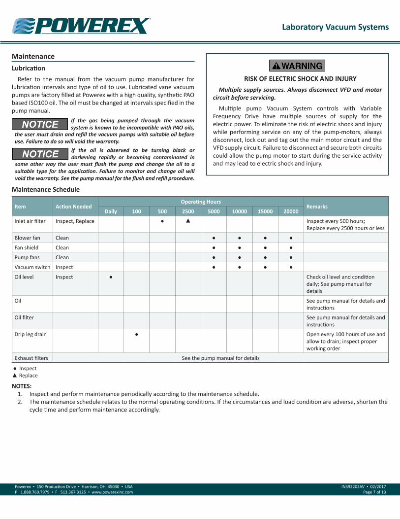
Maintenance Schedule
Item Action NeededOperating Hours
RemarksDaily 100 500 2500 5000 10000 15000 20000
Inlet air filter Inspect, Replace ● ▲ Inspect every 500 hours;Replace every 2500 hours or less
Blower fan Clean ● ● ● ●
Fan shield Clean ● ● ● ●
Pump fans Clean ● ● ● ●
Vacuum switch Inspect ● ● ● ●
Oil level Inspect ● Check oil level and condition daily; See pump manual for details
Oil See pump manual for details and instructions
Oil filter See pump manual for details and instructions
Drip leg drain ● Open every 100 hours of use and allow to drain; inspect proper working order
Exhaust filters See the pump manual for details
● Inspect▲ Replace
NOTES:1. Inspect and perform maintenance periodically according to the maintenance schedule.2. The maintenance schedule relates to the normal operating conditions. If the circumstances and load condition are adverse, shorten the
cycle time and perform maintenance accordingly.
If the oil is observed to be turning black or darkening rapidly or becoming contaminated in
some other way the user must flush the pump and change the oil to a suitable type for the application. Failure to monitor and change oil will void the warranty. See the pump manual for the flush and refill procedure.

Laboratory Vacuum Systems
Powerex • 150 Production Drive • Harrison, OH 45030 • USAP 1.888.769.7979 • F 513.367.3125 • www.powerexinc.com
IN592202AV • 02/2017Page 8 of 13
Troubleshooting Guide
Problem Cause Corrective Action
Lag Alarm Overload Tripped 1. Reset overload; if problem continues, check motor amp draw2. Verify overload is set to the correct service factor3. Verify wire gauge is correct for amp draw
Pump / Motor Failure 1. Check drive coupling; replace if needed2. Verify that pump shaft turns freely; repair or replace as necessary3. Check vacuum discharge piping to verify air is being exhausted; repair or replace as necessary4. Verify voltage to the motor; repair wiring or replace motor as necessary
Vacuum Consumption 1. Repair leaks2. Inspect purge valves are closing; repair or replace as necessary
Switch Failure Check continuity on lead vacuum switch
High Temperature Alarm High Temperature Verify ambient temperature is below 104°F
Lost Connection Inspect high temperature probe and connections; replace if necessary
System has a motor overload fault: Reset the overload, and verify that it is set at 125% of the motor nameplate full load amperage. Verify all motor lead connections at the control panel and in the motor junction box are secure. If there are scorch marks or other signs or heat at the connections, repair or tighten the connection as needed. Verify the voltage during a start up cycle does not drop more than 10% below the nominal circuit voltage. Low voltage will result in high amp draw, slow starting and lead to motor damage. Increase the available amperage in the supply circuit to resolve. If nuisance tripping persists it may be necessary to replace the OL device.
Measure the amp draw while running under normal load. If the amp draw significantly exceeds the motor value, look for the cause. Possible causes are: restricted exhaust filters, deteriorated oil and possible pump degradation from improper lubrication. (If detected early, degraded oil can be changed and proper pump function restored. If pumps are operated for extended time with poor oil lubrication, internal parts can be damaged and require extensive service to restore proper function.
Vacuum pumps run all the time or run more than expected:
NOTE: System includes 10 minute minimum run timers for all motors.
If demand is frequent, the pumps may be seeing a call for and running often. To diagnose, isolate the system from the facility and verify proper control function. Verify that the system does not have significant vacuum leaks while isolated. If the control is working properly and the Powerex system is not experiencing vacuum leaks, then either demand is high or leaks exist in the facility piping that is increasing demand.
Oil is turning dark: Pump is running in ambient conditions that are too hot, or is operating with process gas that is causing oil oxidation and degradation. It may be necessary to change oil and filters more often. Blocked exhaust filters can contribute to hot running.
Oil is milky or creamy: Vacuum pumps are ingesting water. Correct system flow by installing liquid knock out devices ahead of the system intake point. Sustained operation with milky or creamy oil will damage internal pump components requiring extensive rebuilding or pump replacement.
Warranty Coverage & MaintenanceIn the event that a component or system fails or malfunctions,
Powerex will request records or evidence of maintenance activities. Failure to perform maintenance actions will void warranty coverage for those resulting failures or malfunctions.

Laboratory Vacuum Systems
Powerex • 150 Production Drive • Harrison, OH 45030 • USAP 1.888.769.7979 • F 513.367.3125 • www.powerexinc.com
IN592202AV • 02/2017Page 9 of 13
Parts List
MECHANICAL PARTS
System Intake Pipe Size
Intake Flex Hose*
Pump Intake Pipe Size
Pump Intake Flex Hose
Intake Filter Assembly Filter Element Intake Check
Valve Drip Leg Quantity
1 inch VP002005AV 1 inch VP002005AV VP000502AV VP000508AV VP000404AV
D-1403(ALL SYSTEMS) 1/pump
1-1/2 inch VP002002AV 1-1/2 inch VP002002AV VP000519AV VP000509AV VP002002AV
2 inch VP002001AV 2 inch VP002001AV VP000520AV VP000510AV VP000407AV
3 inch VP002006AV 3 inch VP002006AV VP000515AV VP000516AV VP000408AV
*NOTE: The intake flex hose and vacuum gauge only require only 1 piece per system instead of a quantity of 1 piece per pump.
MECHANICAL PARTS
Pump Exhaust Pipe Size
Pump Discharge Flex
Hose
Pneumatic Isolation Purge
Pneumatic and Electric Purge
Electric Isolation Purge
Vacuum Gauge* Quantity
1 inch VP002005AV
IS503300AVIS503302AV
IS503403AV GA031300AV(ALL BASIC SYSEMS)
1/pump1-1/2 inch VP002002AV
2 inch VP002001AV IS503404AV
3 inch VP002006AV IS503301AV IS503405AV
FOR LUBRICATED MODELS ONLY
Description Part Number Quantity*
Full synthetic oil AM004403AV 1 gallon
*NOTE: Quantity of oil needed will vary based on pump model.
Laboratory Vacuum Systems
Powerex • 150 Production Drive • Harrison, OH 45030 • USAP 1.888.769.7979 • F 513.367.3125 • www.powerexinc.com
IN592202AV • 02/2017Page 10 of 13
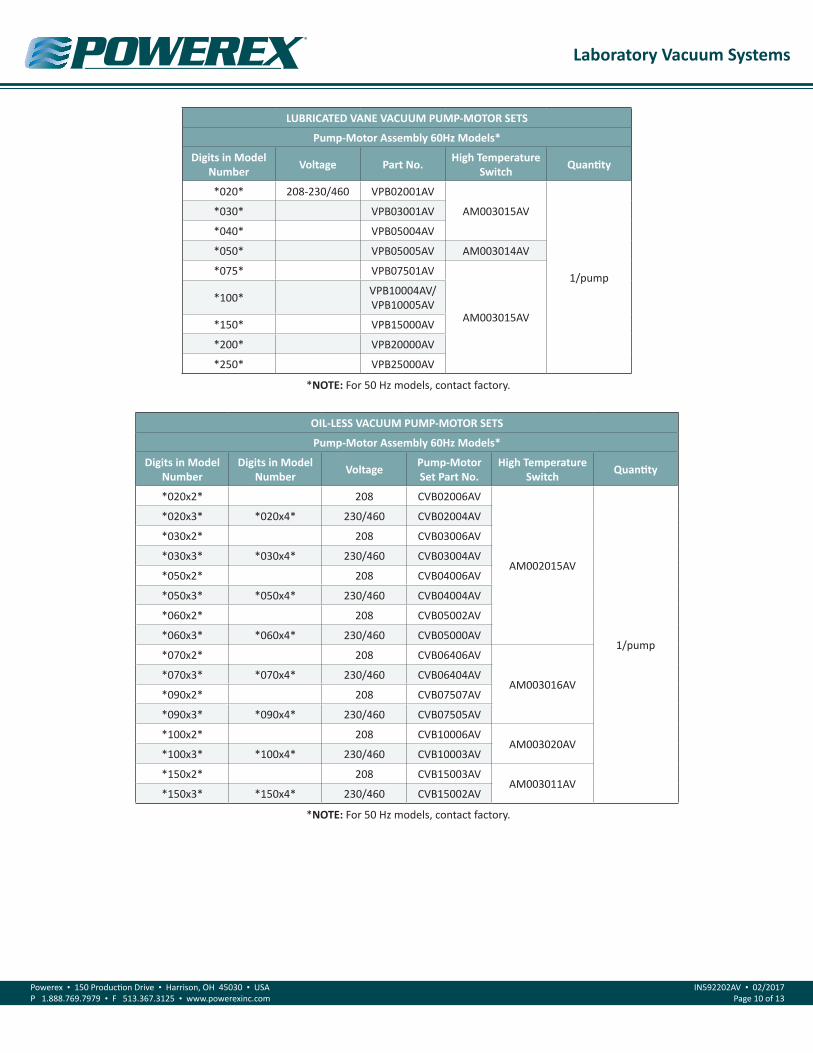
LUBRICATED VANE VACUUM PUMP-MOTOR SETS
Pump-Motor Assembly 60Hz Models*
Digits in Model Number Voltage Part No. High Temperature
Switch Quantity
*020* 208-230/460 VPB02001AV
AM003015AV
1/pump
*030* VPB03001AV
*040* VPB05004AV
*050* VPB05005AV AM003014AV
*075* VPB07501AV
AM003015AV
*100* VPB10004AV/VPB10005AV
*150* VPB15000AV
*200* VPB20000AV
*250* VPB25000AV
*NOTE: For 50 Hz models, contact factory.
OIL-LESS VACUUM PUMP-MOTOR SETS
Pump-Motor Assembly 60Hz Models*
Digits in Model Number
Digits in Model Number Voltage Pump-Motor
Set Part No.High Temperature
Switch Quantity
*020x2* 208 CVB02006AV
AM002015AV
1/pump
*020x3* *020x4* 230/460 CVB02004AV
*030x2* 208 CVB03006AV
*030x3* *030x4* 230/460 CVB03004AV
*050x2* 208 CVB04006AV
*050x3* *050x4* 230/460 CVB04004AV
*060x2* 208 CVB05002AV
*060x3* *060x4* 230/460 CVB05000AV
*070x2* 208 CVB06406AV
AM003016AV*070x3* *070x4* 230/460 CVB06404AV
*090x2* 208 CVB07507AV
*090x3* *090x4* 230/460 CVB07505AV
*100x2* 208 CVB10006AVAM003020AV
*100x3* *100x4* 230/460 CVB10003AV
*150x2* 208 CVB15003AVAM003011AV
*150x3* *150x4* 230/460 CVB15002AV
*NOTE: For 50 Hz models, contact factory.
Laboratory Vacuum Systems
Powerex • 150 Production Drive • Harrison, OH 45030 • USAP 1.888.769.7979 • F 513.367.3125 • www.powerexinc.com
IN592202AV • 02/2017Page 11 of 13
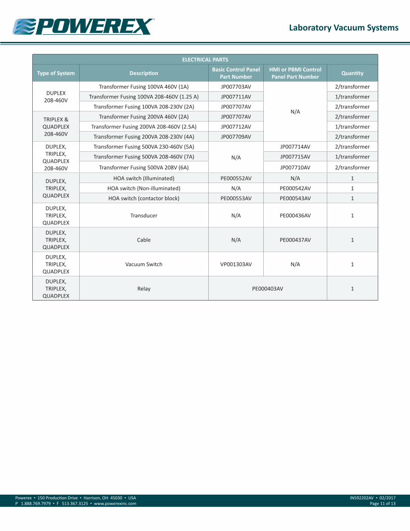
ELECTRICAL PARTS
Type of System Description Basic Control Panel Part Number
HMI or PBMI Control Panel Part Number Quantity
DUPLEX208-460V
Transformer Fusing 100VA 460V (1A) JP007703AV
N/A
2/transformer
Transformer Fusing 100VA 208-460V (1.25 A) JP007711AV 1/transformer
Transformer Fusing 100VA 208-230V (2A) JP007707AV 2/transformer
TRIPLEX & QUADPLEX208-460V
Transformer Fusing 200VA 460V (2A) JP007707AV 2/transformer
Transformer Fusing 200VA 208-460V (2.5A) JP007712AV 1/transformer
Transformer Fusing 200VA 208-230V (4A) JP007709AV 2/transformer
DUPLEX, TRIPLEX,
QUADPLEX208-460V
Transformer Fusing 500VA 230-460V (5A)
N/A
JP007714AV 2/transformer
Transformer Fusing 500VA 208-460V (7A) JP007715AV 1/transformer
Transformer Fusing 500VA 208V (6A) JP007710AV 2/transformer
DUPLEX, TRIPLEX,
QUADPLEX
HOA switch (Illuminated) PE000552AV N/A 1
HOA switch (Non-illuminated) N/A PE000542AV 1
HOA switch (contactor block) PE000553AV PE000543AV 1
DUPLEX, TRIPLEX,
QUADPLEXTransducer N/A PE000436AV 1
DUPLEX, TRIPLEX,
QUADPLEXCable N/A PE000437AV 1
DUPLEX, TRIPLEX,
QUADPLEXVacuum Switch VP001303AV N/A 1
DUPLEX, TRIPLEX,
QUADPLEXRelay PE000403AV 1

Laboratory Vacuum Systems
Powerex • 150 Production Drive • Harrison, OH 45030 • USAP 1.888.769.7979 • F 513.367.3125 • www.powerexinc.com
IN592202AV • 02/2017Page 12 of 13
Powerex Limited Warranty – Applicable to Non-OEM Customers in the U.S. & Canada OnlyWarranty and Remedies. (a) General. Powerex warrants each Compressor System, Vacuum System, Vacuum Pump, Compressor Air-End, or Powerex branded Accessory (collectively “Products”, individually each a “Product”) to be free from defects in material and workmanship (“Defects”) at the date of ship-ment. This warranty shall apply only to Products that are purchased and used in the United States of America and in Canada. EXCEPT AS SET FORTH BELOW, NO OTHER WARRANTY, WHETHER EXPRESS OR IMPLIED, INCLUDING ANY WARRANTY OF MERCHANTABILITY OR FITNESS FOR A PARTICULAR PURPOSE, SHALL EXIST IN CONNECTION WITH THE SALE OR USE OF SUCH PRODUCTS. TO THE EXTENT PERMITTED BY LAW, ANY AND ALL IMPLIED WARRANTIES ARE EXCLUDED. All warranty claims must be made in writing and delivered to Powerex in accordance with the procedures set forth on its website (www.powerexinc.com), or such claim shall be barred. Upon timely receipt of a warranty claim, Powerex shall inspect the Product claimed to have a Defect, and Powerex shall repair, or, at its option, replace, free of charge, any Product which it determines to have had a Defect; provided, however, that if circumstances are such as to preclude the remedying of Defect by repair or replacement, Powerex shall, upon return of the Product, refund to buyer any part of the purchase price of such Products paid to Powerex. Freight for returning Products to Powerex for inspection shall be paid by buyer. The warranties and remedies herein are the sole and exclusive remedy for any breach of warranty or for any other claim based on any Defect, or non-performance of the Products, whether based upon contract, warranty or negligence.
(b) (i) Standard Period of Warranty – Parts and Labor. The purchase of any system includes our standard warranty. Powerex warrants and represents all Products shall be free from Defects for the first eighteen (18) months from the date of shipment by Powerex, or twelve (12) months from the documented date of startup, or five thousand (5,000) hours of use, whichever occurs first. During such warranty period, Powerex shall be fully liable for all Defects in the Products (the “Product Defects”), i.e., all costs of repair or replacement, which may include “in and out” charges, so long as the Products are located in the United States or Canada, and the Products are reasonably located and acces-sible by service personnel for removal. “In and out” charges include the costs of removing a Product from buyer’s equipment for repair or replacement.
(ii) Premium Period of Warranty – Parts and Labor. In order to be eligible for premium warranty coverage, a premium warranty for each system must be purchased when order is placed. Powerex warrants and represents all Products shall be free from Defects for the first thirty (30) months from the date of shipment by Powerex, or twenty-four (24) months from the documented date of startup, or seven thousand five hundred (7,500) hours of use, whichever occurs first. During such warranty period, Powerex shall be fully liable for all Defects in the Products (the “Product Defects”), i.e., all costs of repair or replacement, which may include “in and out” charges, so long as the Products are located in the United States or Canada, and the Products are reasonably located and accessible by service personnel for removal. “In and out” charges include the costs of removing a Product from buyer’s equipment for repair or replacement.
(c) Additional Period of Warranty – Parts Only (No Labor). In addition to the above, Powerex warrants each Powerex branded Compressor Air- End and Vacuum Pump shall be free of Defects for a period of forty-two (42) months from the date of shipment by Powerex, or thirty-six (36) months from the documented date of startup, or ten thousand (10,000) hours of use, whichever occurs first. Supplier’s repair or replace-ment of any Product shall not extend the period of any warranty of any Product. This warranty applies to the exchange of part(s) found to be defective by an Authorized Powerex Service Representative only.
(d) Replacement Pumps – Parts Only (No Labor). For any replacement Air-End or Vacuum Pumps installed on a Powerex manufactured sys-tem or unit after any initial warranty period has expired or where another warranty does not apply for any reason, Powerex warrants that the Air-End or Vacuum Pumps shall be free of Defects for a period of thirty-six (36) months from the date of shipment by Powerex or ten thou-sand (10,000) hours of use, whichever comes first. For any replacement Air-End or Vacuum Pumps installed on a system that was not manu-factured by Powerex after any initial warranty period has expired or where another warranty does not apply for any reason, Powerex warrants that the Air-End or Vacuum Pumps shall be free of Defects for the first twelve (12) months from the date of shipment by Powerex. Supplier’s repair or replacement of any Product shall not extend the period of any warranty of any Product. This warranty applies to the exchange of part(s) found to be defective by an Authorized Powerex Service Representative only.
(e) Replacement Motors – Parts Only (No Labor). For any replacement motor installed on a Powerex manufactured system or unit after any initial warranty period has expired or where another warranty does not apply for any reason, Powerex warrants that the replacement motor shall be free of Defects for the first twelve (12) months from the date of shipment by Powerex. For any replacement motor installed on a system or unit that was not manufactured by Powerex after any initial warranty period has expired or where another warranty does not apply for any reason, Powerex warrants that the replacement motor shall be free of Defects for the first ninety (90) days from the date of shipment by Powerex. Supplier’s repair or replacement of any Product shall not extend the period of any warranty of any Product. This warranty applies to the exchange of part(s) found to be defective by an Authorized Powerex Service Representative only.
(f) Replacement Parts – Parts Only (No Labor). For other replacement parts besides motors, Air-End or Vacuum Pumps installed on a Power-ex manufactured system or unit after any initial warranty period has expired or where another warranty does not apply for any reason, Pow-

Laboratory Vacuum Systems
Powerex • 150 Production Drive • Harrison, OH 45030 • USAP 1.888.769.7979 • F 513.367.3125 • www.powerexinc.com
IN592202AV • 02/2017Page 13 of 13
erex warrants that such replacement parts will be free from Defects for the first twelve (12) months from the date of shipment by Powerex. For other replacement parts besides motors, Air-End or Vacuum Pumps installed on a system or unit that was not manufactured by Powerex after any initial warranty period has expired or where another warranty does not apply for any reason, Powerex warrants that such replace-ment parts will be free from Defects for the first twelve (12) months from the date of shipment by Powerex. For other replacement parts be-sides motors, Air-End or Vacuum Pumps installed on a system or unit that was not manufactured by Powerex after any initial warranty period has expired or where another warranty does not apply for any reason, Powerex makes no warranties. Supplier’s repair or replacement of any Product shall not extend the period of any warranty of any Product. This warranty applies to the exchange of part(s) found to be defective by an Authorized Powerex Service Representative only.
(g) Coverage. The warranty provided herein applies to Powerex manufactured units or systems only.
(h) Exceptions. Notwithstanding anything to the contrary herein, Powerex shall have no warranty obligations with respect to Products:
(i) That have not been installed in accordance with Powerex’s written specifications and instructions;
(ii) That have not been maintained in accordance with Powerex’s written instructions;
(iii) That have been materially modified without the prior written approval of Powerex; or
(iv) That experience failures resulting from operation, either intentional or otherwise, in excess of rated capacities or in an otherwise im-proper manner.
The warranty provided herein shall not apply to: (i) any defects arising from corrosion, abrasion, use of insoluble lubricants, or negligent at-tendance to or faulty operation of the Products; (ii) ordinary wear and tear of the Products; or (iii) defects arising from abnormal conditions of temperature, dirt or corrosive matter; (iv) any OEM component which is shipped by Powerex with the original manufacturer’s warranty, which shall be the sole applicable warranty for such component.
Limitation of Liability. NOTWITHSTANDING ANYTHING TO THE CONTRARY HEREIN, TO THE EXTENT ALLOWABLE UNDER APPLICABLE LAW, UN-DER NO CIRCUMSTANCES SHALL POWEREX BE LIABLE FOR ANY INCIDENTAL, CONSEQUENTIAL, PUNITIVE, SPECULATIVE OR INDIRECT LOSSES OR DAMAGES WHATSOEVER ARISING OUT OF OR IN ANY WAY RELATED TO ANY OF THE PRODUCTS OR GOODS SOLD OR AGREED TO BE SOLD BY POWEREX TO BUYER. TO THE EXTENT ALLOWABLE UNDER APPLICABLE LAW, POWEREX’S LIABILITY IN ALL EVENTS IS LIMITED TO, AND SHALL NOT EXCEED, THE PURCHASE PRICE PAID.
Warranty Disclaimer. Powerex has made a diligent effort to illustrate and describe the Products in its literature, including its Price Book, accu-rately; however, such illustrations and descriptions are for the sole purpose of identification, and do not express or imply a warranty that the Products are merchantable, or fit for a particular purpose, or that the Products will necessarily conform to the illustrations or descriptions.
Product Suitability. Many jurisdictions have codes and regulations governing sales, construction, installation, and/or use of Products for cer-tain purposes, which may vary from those in neighboring areas. While Powerex attempts to assure that its Products comply with such codes, it cannot guarantee compliance, and cannot be responsible for how the product is installed or used. Before purchase and use of a Product, please review the Product applications, and national and local codes and regulations, and be sure that the Product, installation, and use will comply with them.
Claims. Any non-warranty claims pertaining to the Products must be filed with Powerex within 6 months of the invoice date, or they will not be honored. Prices, discounts, and terms are subject to change without notice or as stipulated in specific Product quotations. Powerex shall not be liable for any delay or failure arising out of acts of the public enemy, fire, flood, or any disaster, labor trouble, riot or disorder, delay in the supply of materials or any other cause, whether similar or dissimilar, beyond the control of Company. All shipments are carefully inspected and counted before leaving the factory. Please inspect carefully any receipt of Products noting any discrepancy or damage on the carrier’s freight bill at the time of delivery. Discrepancies or damage which obviously occurred in transit are the carrier’s responsibility and related claims should be made promptly directly to the carrier. Returned Products will not be accepted without prior written authorization by Powerex and deductions from invoices for shortage or damage claims will not be allowed. UNLESS OTHERWISE AGREED TO IN WRITING, THE TERMS AND CONDITIONS CONTAINED IN THIS LIMITED WARRANTY WILL CONTROL IN ANY TRANSACTION WITH POWEREX. Any different or conflicting terms as may appear on any order form now or later submitted by the buyer will not control. All orders are subject to acceptance by Powerex.
Laboratory Vacuum Systems – PXMIPlease read and save these instructions. Read carefully before attempting to assemble, install, operate or maintain the product described. Protect yourself and others by observing all safety information. Failure to comply with instructions could result in personal injury and/or property damage! Retain instructions for future reference.
Description
Powerex • 150 Production Drive • Harrison, OH 45030 • USAP 1.888.769.7979 • F 513.367.3125 • www.powerexinc.com
IN592701AV • 02/2017Page 1 of 15
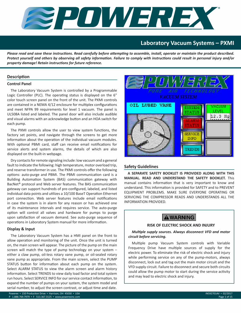
Control PanelThe Laboratory Vacuum System is controlled by a Programmable
Logic Controller (PLC). The operating status is displayed on the 6” color touch screen panel on the front of the unit. The PXMI controls are contained in a NEMA 4/12 enclosure for multiplex configurations and meet NFPA 99 requirements for level 1 vacuum. The panel is UL508A listed and labeled. The panel door will also include audible and visual alarms with an acknowledge button and an HOA switch for each pump.
The PXMI controls allow the user to view system functions, the factory set points, and navigate through the screens to get more information about the operation of the individual vacuum modules. With optional PBMI card, staff can receive email notifications for service alerts and system alarms, the details of which are also displayed on the built-in webpage.
Dry contacts for remote signaling include: low vacuum and a general fault to indicate the following: high temperature, motor overload trip, and reserve transformer in use. The PXMI controls offer the following options: auto-purge and PBMI. The PBMI communication card is a Building Automation System (BAS) communication gateway with BacNet® protocol and Web server features. The BAS communication gateway can support hundreds of pre-configured, labeled, and listed individual data points and utilizes a 10/100 BaseT Operation Ethernet port connection. Web server features include email notifications in case the system is in alarm for any reason or has achieved one of its maintenance intervals and requires service. The auto-purge option will control all valves and hardware for pumps to purge upon satisfaction of vacuum demand. See auto-purge sequence of operations in Laboratory System manual for more information.
Display & InputThe Laboratory Vacuum System has a HMI panel on the front to
allow operation and monitoring of the unit. Once the unit is turned on, the main screen will appear. The picture of the pump on the main screen will match the type of pump technology on your system – either a claw pump, oil-less rotary vane pump, or oil-sealed rotary vane pump as appropriate. From the main screen, select the PUMP STATUS button for information about each pump on the system. Select ALARM STATUS to view the alarm screen and alarm history information. Select TRENDS to view daily load factor and total system run hours. Select SERVICE INFO for our service contact information, to expand the number of pumps on your system, the system model and serial number, to adjust the screen contrast, or adjust time and date.
Safety GuidelinesA SEPARATE SAFETY BOOKLET IS PROVIDED ALONG WITH THIS
MANUAL. READ AND UNDERSTAND THE SAFETY BOOKLET. This manual contains information that is very important to know and understand. This information is provided for SAFETY and to PREVENT EQUIPMENT PROBLEMS. MAKE SURE EVERYONE OPERATING OR SERVICING THE COMPRESSOR READS AND UNDERSTANDS ALL THE INFORMATION PROVIDED.
RISK OF ELECTRIC SHOCK AND INJURYMultiple supply sources. Always disconnect VFD and motor
circuit before servicing.
Multiple pump Vacuum System controls with Variable Frequency Drive have multiple sources of supply for the electric power. To eliminate the risk of electric shock and injury while performing service on any of the pump-motors, always disconnect, lock out and tag out the main motor circuit and the VFD supply circuit. Failure to disconnect and secure both circuits could allow the pump motor to start during the service activity and may lead to electric shock and injury.
Laboratory Vacuum Systems – PXMI
Powerex • 150 Production Drive • Harrison, OH 45030 • USAP 1.888.769.7979 • F 513.367.3125 • www.powerexinc.com
IN592701AV • 02/2017Page 2 of 15
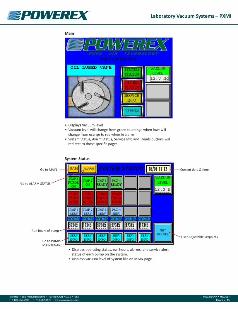
• Displays operating status, run hours, alarms, and service alert status of each pump on the system.
• Displays vacuum level of system like on MAIN page.
System Status
Go to ALARM STATUS
• Displays Vacuum level• Vacuum level will change from green to orange when low; will
change from orange to red when in alarm• System Status, Alarm Status, Service Info and Trends buttons will
redirect to those specific pages.
Main
Go to MAIN
User Adjustable Setpoints
Current date & time
Run hours of pump
Go to PUMP MAINTENANCE
Laboratory Vacuum Systems – PXMI
Powerex • 150 Production Drive • Harrison, OH 45030 • USAP 1.888.769.7979 • F 513.367.3125 • www.powerexinc.com
IN592701AV • 02/2017Page 3 of 15
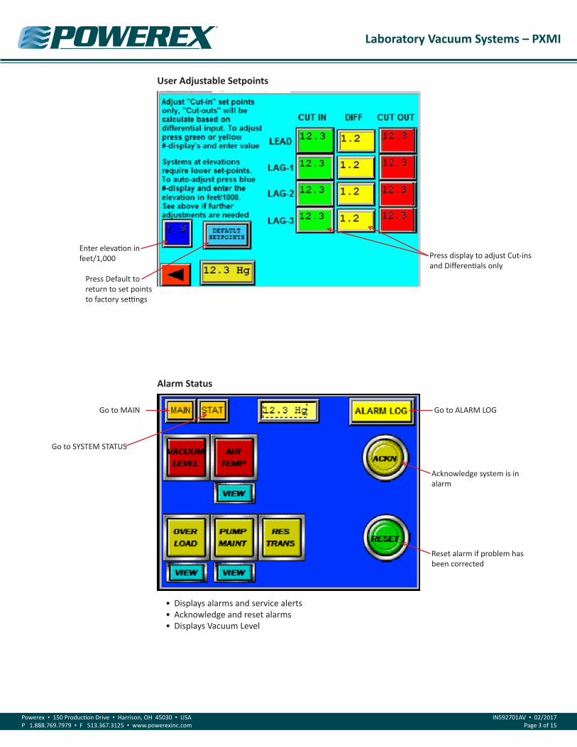
User Adjustable Setpoints
Enter elevation in feet/1,000
Press Default to return to set points to factory settings
Press display to adjust Cut-ins and Differentials only
Alarm Status
• Displays alarms and service alerts• Acknowledge and reset alarms• Displays Vacuum Level
Go to SYSTEM STATUS
Go to MAIN
Reset alarm if problem has been corrected
Go to ALARM LOG
Acknowledge system is in alarm

Laboratory Vacuum Systems – PXMI
Powerex • 150 Production Drive • Harrison, OH 45030 • USAP 1.888.769.7979 • F 513.367.3125 • www.powerexinc.com
IN592701AV • 02/2017Page 4 of 15
• Displays model number, serial number, service phone number• If system is expandable, use Plex Mode Input to adjust PLC
Program to additional pumps
Service
• Record of all alarms, warnings and service alerts with date and time
Alarm Log
Go to ALARM STATUS
Select a specific record
Scroll page up or down to see more records
Go to MAIN
If system is expandable, re-adjust number of pumps
Set time and date
Go to SEQUENCE OF OPERATIONS
Make screen contrast lighter or darker

Laboratory Vacuum Systems – PXMI
Powerex • 150 Production Drive • Harrison, OH 45030 • USAP 1.888.769.7979 • F 513.367.3125 • www.powerexinc.com
IN592701AV • 02/2017Page 5 of 15
• Displays model number, serial number, service phone number• If system is expandable, use Plex Mode Input to adjust PLC
Program to additional pumps
To Set Time and Date
Factory use only
Press “Set time, date” button
This Screen Will Appear
Press “Offline”
Laboratory Vacuum Systems – PXMI
Powerex • 150 Production Drive • Harrison, OH 45030 • USAP 1.888.769.7979 • F 513.367.3125 • www.powerexinc.com
IN592701AV • 02/2017Page 6 of 15
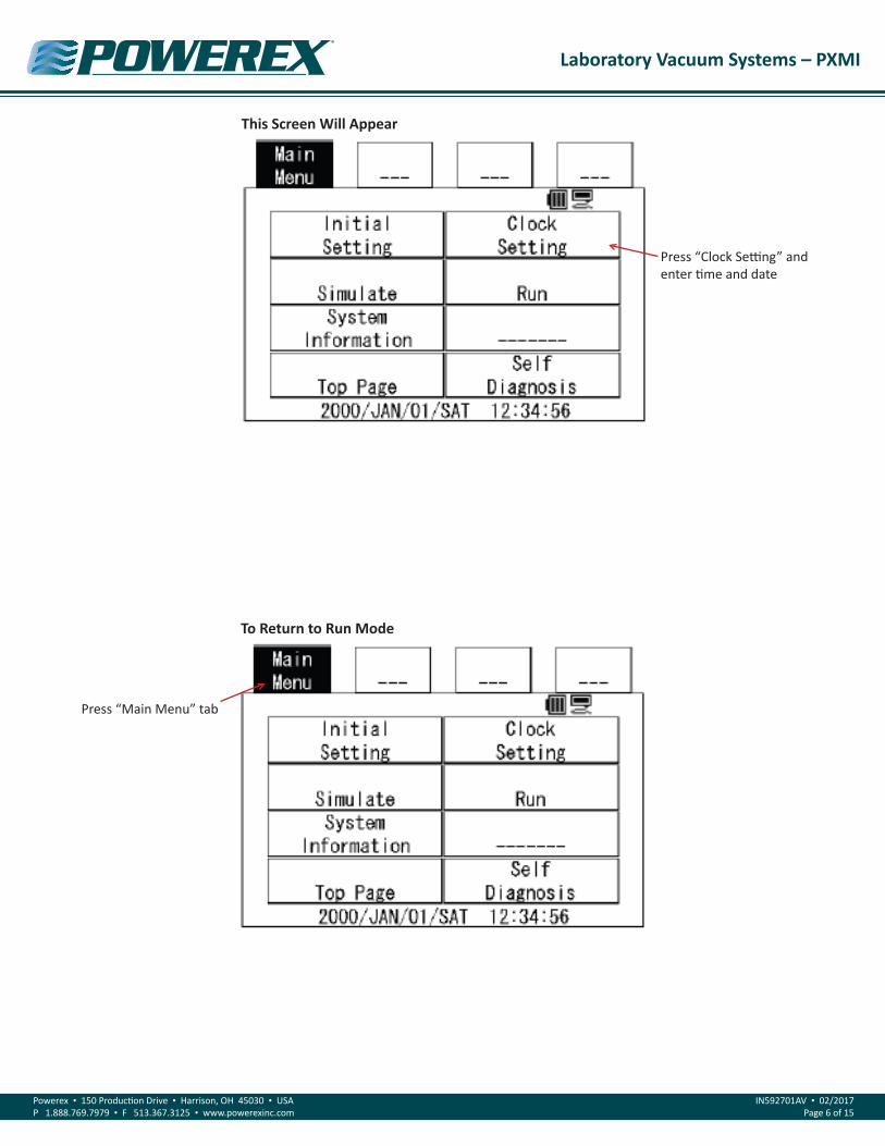
This Screen Will Appear
To Return to Run Mode
Press “Clock Setting” and enter time and date
Press “Main Menu” tab

Laboratory Vacuum Systems – PXMI
Powerex • 150 Production Drive • Harrison, OH 45030 • USAP 1.888.769.7979 • F 513.367.3125 • www.powerexinc.com
IN592701AV • 02/2017Page 7 of 15
This Screen Will Appear
Press “Run” and HMI will return to normal operation and SERVICE screen
Sequence of Operation

Laboratory Vacuum Systems – PXMI
Powerex • 150 Production Drive • Harrison, OH 45030 • USAP 1.888.769.7979 • F 513.367.3125 • www.powerexinc.com
IN592701AV • 02/2017Page 8 of 15
Daily Load Factor
• At specific preset hour intervals, pump maintenance instructions will be displayed; this is specific to each pump
Pump Maintenance
Go to MAIN
Go to MAIN
Laboratory Vacuum Systems – PXMI
Powerex • 150 Production Drive • Harrison, OH 45030 • USAP 1.888.769.7979 • F 513.367.3125 • www.powerexinc.com
IN592701AV • 02/2017Page 9 of 15
Gateway Start UpNOTE: PAGES 9-14 ARE INSTRUCTIONS FOR OPTIONAL PBMI WEBSERVER/BACNET® GATEWAY CARD. THESE INSTRUCTIONS ARE NOT APPLICABLE FOR SYSTEMS WITH HMI ONLY.
Required Tools & DataYou will need the following tools:
• The 260MX-S027 Gateway• The provided CD-ROM• A Working PC (Windows based)• An Ethernet Crossover Cable• A 12-24 VDC power source (T-strip)
OverviewThe 260MX-S027 Gateway device seamlessly connects Modbus RTU Slave devices to a BACnet/IP client. By following this guide, you will
be able to configure the 260MX-S027 Gateway for basic operation. You will set the device’s network settings and parameters to the proper configuration for initial operation and physically place the device in the network.
Network ConnectionsThe Gateway is shipped out with a Default IP Address of 172.16.3.159 and a Subnet of 255.255.248.0. In order to browse for the gateway’s
main page and begin configuring the gateway, you must change your PC to be on the same network as the gateway.
1. Change the IP Address of your PC to be 172.16.3.158
2. Change the Subnet of your PC to be 255.255.248.0
3. Open IPSetup.exe and browse for the gateway under select a unit.
4. Change the IP Address and Subnet to be on your network.
5. Click Set.
6. Change the PC’s IP Address and Subnet back to its original settings.
7. Browse for the Unit using IPSetup.exe and launch the webpage.

Laboratory Vacuum Systems – PXMI
Powerex • 150 Production Drive • Harrison, OH 45030 • USAP 1.888.769.7979 • F 513.367.3125 • www.powerexinc.com
IN592701AV • 02/2017Page 10 of 15
Accessing the Main PageBefore you can configure the gateway itself, you must configure
the network settings to connect the gateway. The following steps will connect the gateway properly.
1. Connect the 12-24 VDC power source to the device.
2. Using the crossover cable, connect the device to the PC.
3. Insert the provided CD-ROM.
4. Run the IPSetup program from the CD-ROM.
5. Configure the IP Settings based on your subnet.
6. Click Set.
7. Click Launch Webpage. The Main page should appear.
NOTE: Browser configuration is compatible with Chrome, Internet Explorer, and Firefox. Default IP address is 172.16.3.159
Error: Main Pain Does Not LaunchIf the Main Page does not launch the IP Address is most likely
incorrect. Correct the IP Address and try again. If you do not know the IP Address use the following procedure:
1. Open an MS-DOS Command Prompt.
2. Type ipconfig and press enter.
3. Note the IP address. (The previous example was 172.16.3.158)
4. To test the communication between the PC and the unit type ping (###.###.###.###) in the prompt and press Enter. The (###.###.###.###) is the IP address of the unit you used in step 5 of network configuration, which is 172.16.3.159 by default. If the device is connected to the network the ping will show a response. If you get no response check the crossover cable.

Laboratory Vacuum Systems – PXMI
Powerex • 150 Production Drive • Harrison, OH 45030 • USAP 1.888.769.7979 • F 513.367.3125 • www.powerexinc.com
IN592701AV • 02/2017Page 11 of 15
BACnet®/IP Server Settings1. Click Edit next to the BACnet® Server row. Verify that the
Enabled box is checked.
2. Enter the Device Instance that corresponds with your BACnet®/IP Server device.
3. In the Device Name field enter a unique name for the device.
4. The Description and Location fields are optional. Filling in this information is recommended to identify the device on a network.
5. Beneath # of Objects to Expose, enter in the number of Analog Input (AI), Analog Output (AO), Binary Input (BI), and/or Binary Output (BO) objects that you will be accessing from the BACnet®/IP Client.
6. Click Save.
Alarm Configuration1. Click Edit next within the Alarm Configuration section from the
Main Page.
2. To enable an alarm, check the box within the Enable/ Disable column.
3. If an alarm is enabled, then the Low Alarm and High Alarm must be set.
4. If the value of the point falls below the Low Alarm, the alarm is set and an e-mail is generated if e-mail is configured.
5. If the value of the point reaches the High Alarm, the alarm is set and an e-mail is generated if e-mail is configured.
6. Scroll to the bottom and Save.

Laboratory Vacuum Systems – PXMI
Powerex • 150 Production Drive • Harrison, OH 45030 • USAP 1.888.769.7979 • F 513.367.3125 • www.powerexinc.com
IN592701AV • 02/2017Page 12 of 15
Email Configuration1. Click Edit next to the Email Configuration section from the Main
Page
2. Enter a SMTP Mail Username. This e-mail must have SMTP capability set up.
3. If the SMTP device requires authentication, please enter in the Password for the SMTP Mail Username.
4. Enter in the SMTP Server that is being used.
5. Enter in the Email Address of the sender. This is going to be the same field as Step 2
6. Enter in the Email Address of the recipient.
7. Repeat steps 2-6 for multiple recipients.
8. Enter the Subject of the Email to be sent. This will be used for all 3 e-mails.
9. Enter an extension of the Message Body. Every Email will have a Body of Email that specifies the Alarm and the value of the current alarm that was triggered. This field will be added after the standard body.
10. Click Save.
11. Click Send Test Email to verify all of the Email settings are correct.
System Status1. This page shows the Modbus Point, Point Name, Value, and if an
Alarm is set, the Low and High Alarm.
2. The value will show the current value of the point upon a Refresh of this page.
3. If an alarm is enabled and is triggered, the point in an alarm state will be displayed in Red.
Laboratory Vacuum Systems – PXMI
Powerex • 150 Production Drive • Harrison, OH 45030 • USAP 1.888.769.7979 • F 513.367.3125 • www.powerexinc.com
IN592701AV • 02/2017Page 13 of 15
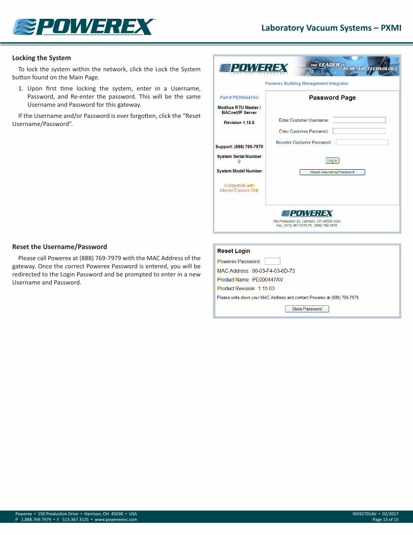
Locking the SystemTo lock the system within the network, click the Lock the System
button found on the Main Page.
1. Upon first time locking the system, enter in a Username, Password, and Re-enter the password. This will be the same Username and Password for this gateway.
If the Username and/or Password is ever forgotten, click the “Reset Username/Password”.
Reset the Username/PasswordPlease call Powerex at (888) 769-7979 with the MAC Address of the
gateway. Once the correct Powerex Password is entered, you will be redirected to the Login Password and be prompted to enter in a new Username and Password.
Laboratory Vacuum Systems – PXMI
Powerex • 150 Production Drive • Harrison, OH 45030 • USAP 1.888.769.7979 • F 513.367.3125 • www.powerexinc.com
IN592701AV • 02/2017Page 14 of 15
Powerex Limited Warranty – Applicable to Non-OEM Customers in the U.S. & Canada OnlyWarranty and Remedies.(a) General. Powerex warrants each Compressor System, Vacuum System, Vacuum Pump, Compressor Air-End, or Powerex branded Accessory (collectively “Products”, individually each a “Product”) to be free from defects in material and workmanship (“Defects”) at the date of shipment. This warranty shall apply only to Products that are purchased and used in the United States of America and in Canada. EXCEPT AS SET FORTH BELOW, NO OTHER WARRANTY, WHETHER EXPRESS OR IMPLIED, INCLUDING ANY WARRANTY OF MERCHANTABILITY OR FITNESS FOR A PARTICULAR PURPOSE, SHALL EXIST IN CONNECTION WITH THE SALE OR USE OF SUCH PRODUCTS. TO THE EXTENT PERMITTED BY LAW, ANY AND ALL IMPLIED WARRANTIES ARE EXCLUDED. All warranty claims must be made in writing and delivered to Powerex in accordance with the procedures set forth on its website (www.powerexinc.com), or such claim shall be barred. Upon timely receipt of a warranty claim, Powerex shall inspect the Product claimed to have a Defect, and Powerex shall repair, or, at its option, replace, free of charge, any Product which it determines to have had a Defect; provided, however, that if circumstances are such as to preclude the remedying of Defect by repair or replacement, Powerex shall, upon return of the Product, refund to buyer any part of the purchase price of such Products paid to Powerex. Freight for returning Products to Powerex for inspection shall be paid by buyer. The warranties and remedies herein are the sole and exclusive remedy for any breach of warranty or for any other claim based on any Defect, or non-performance of the Products, whether based upon contract, warranty or negligence.
(b) (i) Standard Period of Warranty – Parts and Labor. The purchase of any system includes our standard warranty. Powerex warrants and represents all Products shall be free from Defects for the first eighteen (18) months from the date of shipment by Powerex, or twelve (12) months from the documented date of startup, or five thousand (5,000) hours of use, whichever occurs first. During such warranty period, Powerex shall be fully liable for all Defects in the Products (the “Product Defects”), i.e., all costs of repair or replacement, which may include “in and out” charges, so long as the Products are located in the United States or Canada, and the Products are reasonably located and accessible by service personnel for removal. “In and out” charges include the costs of removing a Product from buyer’s equipment for repair or replacement.
(ii) Premium Period of Warranty – Parts and Labor. In order to be eligible for premium warranty coverage, a premium warranty for each system must be purchased when order is placed. Powerex warrants and represents all Products shall be free from Defects for the first thirty (30) months from the date of shipment by Powerex, or twenty-four (24) months from the documented date of startup, or seven thousand five hundred (7,500) hours of use, whichever occurs first. During such warranty period, Powerex shall be fully liable for all Defects in the Products (the “Product Defects”), i.e., all costs of repair or replacement, which may include “in and out” charges, so long as the Products are located in the United States or Canada, and the Products are reasonably located and accessible by service personnel for removal. “In and out” charges include the costs of removing a Product from buyer’s equipment for repair or replacement.
(c) Additional Period of Warranty – Parts Only (No Labor). In addition to the above, Powerex warrants each Powerex branded Compressor Air- End and Vacuum Pump shall be free of Defects for a period of forty-two (42) months from the date of shipment by Powerex, or thirty-six (36) months from the documented date of startup, or ten thousand (10,000) hours of use, whichever occurs first. Supplier’s repair or replacement of any Product shall not extend the period of any warranty of any Product. This warranty applies to the exchange of part(s) found to be defective by an Authorized Powerex Service Representative only.
(d) Replacement Pumps – Parts Only (No Labor). For any replacement Air-End or Vacuum Pumps installed on a Powerex manufactured system or unit after any initial warranty period has expired or where another warranty does not apply for any reason, Powerex warrants that the Air-End or Vacuum Pumps shall be free of Defects for a period of thirty-six (36) months from the date of shipment by Powerex or ten thousand (10,000) hours of use, whichever comes first. For any replacement Air-End or Vacuum Pumps installed on a system that was not manufactured by Powerex after any initial warranty period has expired or where another warranty does not apply for any reason, Powerex warrants that the Air-End or Vacuum Pumps shall be free of Defects for the first twelve (12) months from the date of shipment by Powerex. Supplier’s repair or replacement of any Product shall not extend the period of any warranty of any Product. This warranty applies to the exchange of part(s) found to be defective by an Authorized Powerex Service Representative only.
(e) Replacement Motors – Parts Only (No Labor). For any replacement motor installed on a Powerex manufactured system or unit after any initial warranty period has expired or where another warranty does not apply for any reason, Powerex warrants that the replacement motor shall be free of Defects for the first twelve (12) months from the date of shipment by Powerex. For any replacement motor installed on a system or unit that was not manufactured by Powerex after any initial warranty period has expired or where another warranty does not apply for any reason, Powerex warrants that the replacement motor shall be free of Defects for the first ninety (90) days from the date of shipment by Powerex. Supplier’s repair or replacement of any Product shall not extend the period of any warranty of any Product. This warranty applies to the exchange of part(s) found to be defective by an Authorized Powerex Service Representative only.
(f) Replacement Parts – Parts Only (No Labor). For other replacement parts besides motors, Air-End or Vacuum Pumps installed on a Powerex manufactured system or unit after any initial warranty period has expired or where another warranty does not apply for any reason, Powerex warrants that such replacement parts will be free from Defects for the first twelve (12) months from the date of shipment by Powerex. For other
Laboratory Vacuum Systems – PXMI
Powerex • 150 Production Drive • Harrison, OH 45030 • USAP 1.888.769.7979 • F 513.367.3125 • www.powerexinc.com
IN592701AV • 02/2017Page 15 of 15
replacement parts besides motors, Air-End or Vacuum Pumps installed on a system or unit that was not manufactured by Powerex after any initial warranty period has expired or where another warranty does not apply for any reason, Powerex warrants that such replacement parts will be free from Defects for the first twelve (12) months from the date of shipment by Powerex. For other replacement parts besides motors, Air-End or Vacuum Pumps installed on a system or unit that was not manufactured by Powerex after any initial warranty period has expired or where another warranty does not apply for any reason, Powerex makes no warranties. Supplier’s repair or replacement of any Product shall not extend the period of any warranty of any Product. This warranty applies to the exchange of part(s) found to be defective by an Authorized Powerex Service Representative only.
(g) Coverage. The warranty provided herein applies to Powerex manufactured units or systems only.
(h) Exceptions. Notwithstanding anything to the contrary herein, Powerex shall have no warranty obligations with respect to Products:
(i) That have not been installed in accordance with Powerex’s written specifications and instructions;
(ii) That have not been maintained in accordance with Powerex’s written instructions;
(iii) That have been materially modified without the prior written approval of Powerex; or
(iv) That experience failures resulting from operation, either intentional or otherwise, in excess of rated capacities or in an otherwise improper manner.
The warranty provided herein shall not apply to: (i) any defects arising from corrosion, abrasion, use of insoluble lubricants, or negligent attendance to or faulty operation of the Products; (ii) ordinary wear and tear of the Products; or (iii) defects arising from abnormal conditions of temperature, dirt or corrosive matter; (iv) any OEM component which is shipped by Powerex with the original manufacturer’s warranty, which shall be the sole applicable warranty for such component.
Limitation of Liability. NOTWITHSTANDING ANYTHING TO THE CONTRARY HEREIN, TO THE EXTENT ALLOWABLE UNDER APPLICABLE LAW, UNDER NO CIRCUMSTANCES SHALL POWEREX BE LIABLE FOR ANY INCIDENTAL, CONSEQUENTAL, PUNITIVE, SPECULATIVE OR INDIRECT LOSSES OR DAMAGES WHATSOEVER ARISING OUT OF OR IN ANY WAY RELATED TO ANY OF THE PRODUCTS OR GOODS SOLD OR AGREED TO BE SOLD BY POWEREX TO BUYER. TO THE EXTENT ALLOWABLE UNDER APPLICABLE LAW, POWEREX’S LIABILITY IN ALL EVENTS IS LIMITED TO, AND SHALL NOT EXCEED, THE PURCHASE PRICE PAID.
Warranty Disclaimer. Powerex has made a diligent effort to illustrate and describe the Products in its literature, including its Price Book, accurately; however, such illustrations and descriptions are for the sole purpose of identification, and do not express or imply a warranty that the Products are merchantable, or fit for a particular purpose, or that the Products will necessarily conform to the illustrations or descriptions.
Product Suitability. Many jurisdictions have codes and regulations governing sales, construction, installation, and/or use of Products for certain purposes, which may vary from those in neighboring areas. While Powerex attempts to assure that its Products comply with such codes, it cannot guarantee compliance, and cannot be responsible for how the product is installed or used. Before purchase and use of a Product, please review the Product applications, and national and local codes and regulations, and be sure that the Product, installation, and use will comply with them.
Claims. Any non-warranty claims pertaining to the Products must be filed with Powerex within 6 months of the invoice date, or they will not be honored. Prices, discounts, and terms are subject to change without notice or as stipulated in specific Product quotations. Powerex shall not be liable for any delay or failure arising out of acts of the public enemy, fire, flood, or any disaster, labor trouble, riot or disorder, delay in the supply of materials or any other cause, whether similar or dissimilar, beyond the control of Company. All shipments are carefully inspected and counted before leaving the factory. Please inspect carefully any receipt of Products noting any discrepancy or damage on the carrier’s freight bill at the time of delivery. Discrepancies or damage which obviously occurred in transit are the carrier’s responsibility and related claims should be made promptly directly to the carrier. Returned Products will not be accepted without prior written authorization by Powerex and deductions from invoices for shortage or damage claims will not be allowed. UNLESS OTHERWISE AGREED TO IN WRITING, THE TERMS AND CONDITIONS CONTAINED IN THIS LIMITED WARRANTY WILL CONTROL IN ANY TRANSACTION WITH POWEREX. Any different or conflicting terms as may appear on any order form now or later submitted by the buyer will not control. All orders are subject to acceptance by Powerex.