Embed Size (px)
Citation preview

Mounting Power Semiconductors Powerex, Inc., 173 Pavilion Lane, Youngwood, Pennsylvania 15697 (724) 925-7272
Rev. 1 (10/11) 1
Mounting Surface Preparation
Surface flatness in the device mounting interface area should be .001 inch per inch. Generally, commercial extruded heatsinks require spot facing and cast sinks. Rough plates, etc. require additional machining to meet the required surface flatness requirements.
Surface finish in the device mounting interface area should be equivalent to that of the semiconductor device or 32 micro-inches maximum for disc and 63 micro-inches maximum for stud. Finer finishes add undue cost with little or no improvement in thermal performance.
Care should be taken in handling devices as well as the heatsinks so as to minimize voids, nicks, deep scratches and other imperfections in the mounting interface area. While minor scratches etc. are not desirable, one should realize that surface flatness is much more critical than surface finish in achieving a good thermal interface.
Treated heatsink finishes should be removed from the device mounting interface area. Black anodized or paint on heatsinks must be removed from the mounting area. Also, irridite or chromate acid dip finishes must be removed from the mounting area for optimum performance. Nickel and tin plated finishes are acceptable and even desirable in many applications where corrosion could be a problem.
Mounting interface areas should be free of all foreignmaterial, oxides and films. Since most heatsinks are stored and are not assembled immediately after machining, a cleaning operation is recommended. A satisfactory cleaning technique is to lightly polish the mounting area with a # 000 fine steel wool, followed by a semiconductor cleaning solvent wipe. As freshly bared aluminum forms an oxide layer in a matter of seconds, an electrical joint compound may be used to clean aluminum heatsink mounting surfaces followed by a semiconductor cleaning solvent. Surface should not be touched after cleaning. Parts may be placed on a lint free surface until final assembly. After cleaning, an appropriate thermalinterface compound should be immediately applied and the semiconductor device attached to prevent the thermal compound from collecting dust and metal particles.
Tips for Applying Thermal Interface Compounds
Powerex recommends the use of a thermal interface compound for all power semiconductors. With the proper application of a thermal interface compound to fill the air voids, scratches and imperfections in the device/heatsink mounting interface area, one can achieve up to a twenty-fold improvement in device case-to-sink thermal resistanceas well as decrease in oxidation or corrosion. When properly applied and mounted per the recommendations included here, the use of thermal compounds will allow the user to meet the case-to-sink thermal resistance values published on the Powerex device datasheet.
• Always perform the necessary mounting surfacepre-paration prior to application of the thermalinterface compound.
• Select the appropriate thermal interface compound for your application. Note the temperature limitations, advantages, disadvantages, etc. to see that they are compatible with your needs.
• Thermal interface compound may be applied to the device mounting interface(s) only, provided device/heatsink flatness, finish and surface cleaning have been properly performed.
• Apply appropriate thermal interface compound in a very thin film to the device mounting interface(s) as well as tothe heatsink mounting surface(s). Rotate the device on the heatsink(s) to spread compound and to seat the device.
• Wipe away excess compound from edges of thecontact area with a semiconductor cleaning solvent and a lint-free towel after mounting the device. Otherwise,thermal compound on the insulator(glass or ceramic) housing could collect dust and metal particles andcause arc-over.
• Use thermal interface compound sparingly. Applying too much compound is a major cause of device mounting problems. The thermal interface compound should appear only as a thin, moist film when properly applied to a mounting surface.
Thermal Interface Components
rerutcafunaM
gninroCwoD
Press Packs Studs
DC 200 DC 340
Mounting Power Semiconductors Powerex, Inc., 173 Pavilion Lane, Youngwood, Pennsylvania 15697 (724) 925-7272
Rev. 0 (04/09) 2
Mounting Tips for Stud Devices
• Mount studs to a heatsink through a clearance hole by means of (1) hex nut and a lock washer or pal nut or (2) hex nut-belleville washer combination or hex tenz nut.
• Diameter of the mounting clearance hole should not exceed the diameter of the stud by more than 1/64” and should be accurately drilled perpendicular to the mounting surface.
• Remove projections from mounting clearance hole.
Punched and drilled holes should be carefully de-burred. The edge of the hole may be de-burred with a chamfer not exceeding .01” radius.
• Avoid drilling and tapping holes for stud devices.
Thermal ratcheting which tends to unscrew the stud from the hole can occur and the 1/10 of a degree perpendicularity tolerance necessary between the hole and mounting surface is difficult to achieve.
• Apply appropriate thermal interface compound in a very
thin film to the mounting area only of the device as well as to the mounting surface of the heatsink. Rotate the stud device on the heatsink to spread compound and to seat the device. The threads of the stud and nut must not be lubricated as this will drastically alter the recommended mounting torque and cause undue stress on the stud device. (See Tips for Applying Thermal Interface Compounds)
• Always use a torque wrench when mounting stud
devices. Refer to the individual device datasheet for the correct torque to be used. A good quality torque wrench, accurate in the specified range, should always be used. The torque should always be applied on the hex nut while holding the semiconductor stationary.
• Do not exceed maximum recommended torque limits.
Application of excessive torque is a major cause of stud device mounting problems. Semiconductors can be mechanically damaged by too much torque or thermally damaged by too little.
Mounting Tips for Disc Devices
• Machine or spot face the heatsink mounting surface areas to a diameter larger than that of the disc pole face to be mounted. Keep spot face shallow to prevent interference with other parts of the disc package.
• Use locating pins (or alternative method) to center the
disc for optimum load distribution. Preassemble roll pins with a light hammer into center dowel hole in each heatsink. A gauge block is useful to prevent excessive pin length. Major causes of disc device mounting problems are improperly mounting disc off center or using a locating pin too long and/or wrong diameter, resulting in improper device seating and possibly fracturing the silicon element.
• Check the polarity of the device prior to assembly to
insure the device is installed in the desired direction. Also position SCR gate leads, etc. prior to assembly.
• Mounting of disc devices demands the use of a clamp to
exert a precise force in accordance with values indicated by the semiconductor manufacturer. It also aids in good electrical performance and a low thermal resistance.
Powerex Offers Full Range of Bar Clamps
Powerex offers a full range of precision bar clamps to accommodate semiconductor devices with a required force range of 2kN – 80 kN and 19mm to 100mm mounting surface diameter. The two-bolt clamp system utilizes spring type washers to achieve the required clamping force for the device. This force is achieved when the spring washers are compressed to a specific point, whereby the indicator tab or washer is able to rotate freely. This type of pre-calibrated pressure indicator system eliminates the need for any special tools. The bolt insulator material has been specially designed to ensure excellent dielectric performance, mechanical compression strength and stable high temperature performance.
Mounting Power Semiconductors Powerex, Inc., 173 Pavilion Lane, Youngwood, Pennsylvania 15697 (724) 925-7272
Rev. 0 (04/09) 3
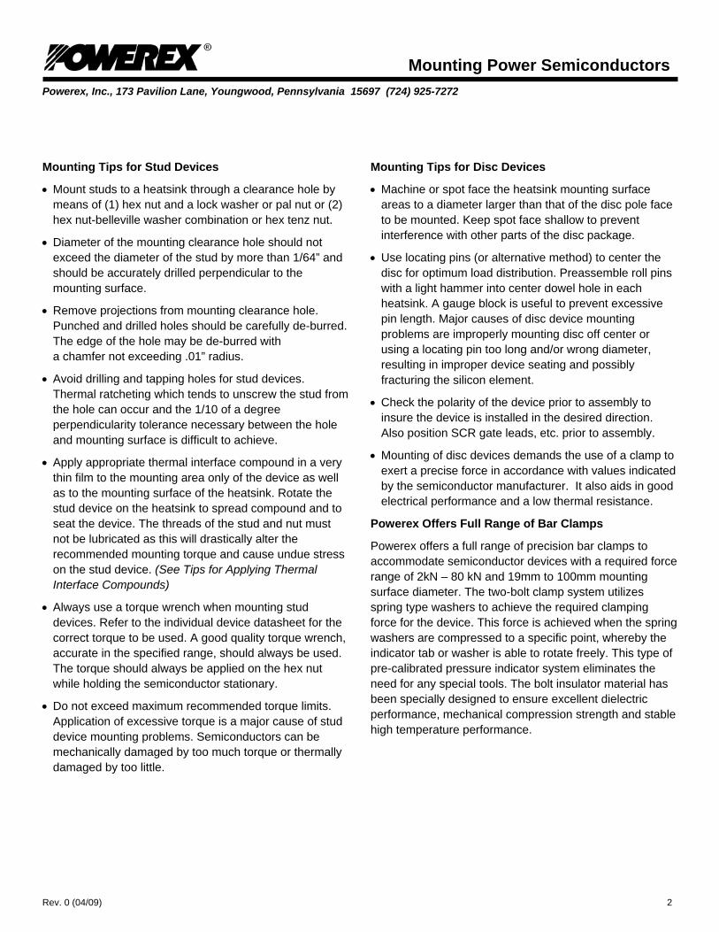
Powerex Bar Clamp Installation Procedures
Powerex bar clamps have a preloaded, cup-shaped, spring system that ensures perpendicular clamping force when used properly.
The release of an indicator tab(s) or washer(s) on the top of the loader bar indicates the achievement of the correct mounting force.
Do not loosen or tighten the bolts holding the spring washer assemblies. Doing so will put the clamp out of calibration.
Always insert washer inside the cup with round side up facing the open end of the cup.
For all clamps with a required force range above 22kN, it is recommended that the bolt threads be coated with an anti-seize compound before installing.
Prior to assembly, take necessary safety precautions to prevent bodily harm as high load forces can result in clamp breakage, resulting in the broken bolt becoming a flying projectile.
First assemble the clamp connecting the heat sinks. Then tighten the bolts alternatively with a socket wrench until the bolt makes contact with the metal washer in the insulator cup.
Mounting Power Semiconductors Powerex, Inc., 173 Pavilion Lane, Youngwood, Pennsylvania 15697 (724) 925-7272
Rev. 0 (04/09) 4
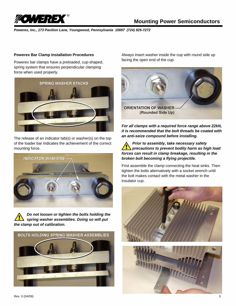
It is important to make sure the bolts are threaded evenly. You can check this by making sure the same amount of threads appear on each side of the bottom bar.
Check that the top bar is parallel with the heat sink and make sure that it is centrally located. (Not at an angle to the channel in the heat sink).
Check the parallel alignment of the heat sinks. Ensure centering pins are aligned and properly seated. Loosen and realign if necessary.
Start by tightening both bolts 1/4 turn.
Proceed to alternately tighten bolts by 1/8 turn, checking the pressure indicator tab each time until one or both indicating tab(s) or washer(s) just turns free. Then tighten the bolt opposite to the side that last released 1/8 of a turn. Correct pressure is achieved when the indicator tab(s) or washers(s) turn freely.
For clamps with two sets of spring washer stacks/indicators, if one side releases before the other, continue to turn the unreleased side by 1/16 until that washer is released.
If the unreleased washer does not release after 5 x 1/16 turns, remove clamp completely. Allow the clamp spring washers to relax for 1/2 hour before starting over.
DO NOT OVERTIGHTEN!

Mounting Power Semiconductors Powerex, Inc., 173 Pavilion Lane, Youngwood, Pennsylvania 15697 (724) 925-7272
Rev. 0 (04/09) 5
Follow these clamping tips for installing all other bar clamps.
• Use a self-leveling type mounting clamp to ensure parallelism and even distribution of pressure.
• Select the proper size clamp. Be aware of clamp
insulation temperature limitations (less than 130°C for most clamps).
• Coat clamp threads for large area discs with an anti-
seize or equivalent type compound, in order to prevent nut and clamp thread binding when high clamping forces are being applied.
• Take necessary safety precautions to prevent bodily
harm as high load forces can result in clamp breakage, resulting in the broken bolt becoming a flying projectile.
• Pre-stressing the clamp to its rated force prior to actual
use in the application can help to seat clamp springs and to screen out defective clamps.
• Preset indicators to zero before assembly on clamps that
have deflection type indicators.
• Apply clamping force smoothly, evenly and perpendicularly to the disc.
• Advance nuts onto clamp bolts equal length and finger
tighten before tightening with a wrench. • • Apply the correct force as described on the device
datasheet. Should too much force be applied to the clamp, do not attempt to back down force. Start clamping procedure all over again. Manual Method – Using an appropriate wrench, alternately advance nuts 1/4 turn each until either the clamp indicator gauge reads the desires force or the required number of turns are applied, depending on type of clamp used. Hydraulic Press Method – Apply the calibrated force to the assembly with press. Using a good quality torque wrench, torque each nut 1/4 turn alternately to 10 ft. lbs. torque. Release press.
• Install disc devices in such a way that the clamping force will always be centered on the semiconductor so as not to be affected by electrical connections or supports. Only one of the two heatsinks may be rigidly attached to a bus bar or a mounting bracket. Cable and bus bar connections that tie to the other heatsinks must be flexible or have stress relief built-in.
• Develop a thorough disc mounting procedure as
attention to each and every detail in mounting a disc is much more critical than in mounting a stud device.