Embed Size (px)
Citation preview

www.isola-group.com
Laminate & Prepreg
Manufacturing

www.isola-group.com
p Manufacturing Focusp Internal contamination Reduction - Controlled environment, Treating technology, handling and lay up
technology.p Prepreg Consistency - Resin content control, On Line cure monitoring, Redundancy with FTIR, Melt viscosity
and Gelationp Surface quality - Lay up Technologyp Controlled thickness .
p Costp Productivity enhancement through lean manufacturing, Re engineered Processes
p QTAp Fast turn around capability through cycle time reduction, sophisticated scheduling and equipment capability
Manufacturing Technology Focus
B-stage for Laminate
for PWBLamination
p Treatingp Gamma Gauges for Resin
content controlp On line DCM’s, MMV’s, FTIR’s p High Shear mixing equipment,
Dedicated lines, Filtration systems
p Lay upp Sandwich copper
concept, separate rooms.p Controlled Clean room
environment with Humidity and static control.
p Pressp High temperature
pressing capabilityp Finishing
p High Speed and precise finishing capability.

www.isola-group.com
Material Building Blocks
Glass• Glass fabric is available in different roll widths and thicknesses• Some glass fabrics are different between North America, Asia Pacific and Europe• Core constructions are different depending on the region and OEM spec.
Resin• The resin is determined by what properties are needed to make a particular MLB design function. ie. Tg, Dk, Df etc.• The resin must be compatible with the glass fabric• The resin must be compatible with the copper foil
Copper• Copper is designated by wt and foil type i.e. Reverse Treat ( RTF ), HTE, Double Treat or std ED copper foil• The copper used must be able to achieve good peel strengths so the copper does not pull away from the glass and resin.
www.isola-group.com
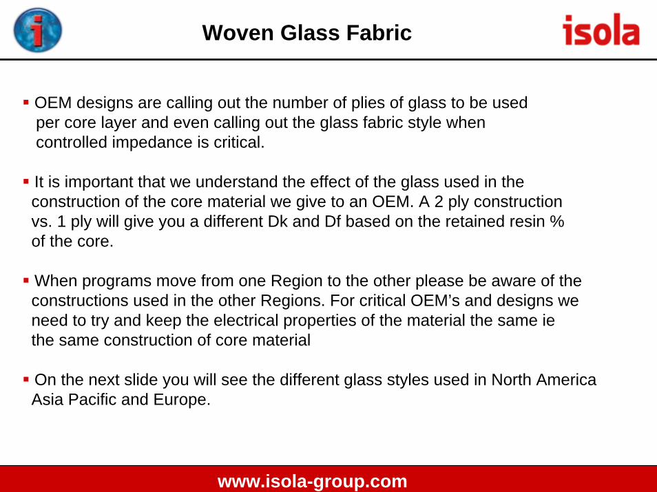
OEM designs are calling out the number of plies of glass to be usedper core layer and even calling out the glass fabric style when controlled impedance is critical.
It is important that we understand the effect of the glass used in theconstruction of the core material we give to an OEM. A 2 ply constructionvs. 1 ply will give you a different Dk and Df based on the retained resin %of the core.
When programs move from one Region to the other please be aware of theconstructions used in the other Regions. For critical OEM’s and designs weneed to try and keep the electrical properties of the material the same ie the same construction of core material
On the next slide you will see the different glass styles used in North AmericaAsia Pacific and Europe.
Woven Glass Fabric
www.isola-group.com
Glass Fabric

www.isola-group.com
Glass Fabric
Glass Weave Warp Fill Warp Fill Fabric Fabric Fabric FabricStyle Count Count Yarn Yarn Thickness Thickness Nominal Weight Nominal Weight
inches mm OSY g/m2
1067 Plain 70 70 ECD 900-1/0 ECD 900-1/0 0.0013 0.032 0.91 31106 Plain 56 56 ECD 900-1/0 ECD 900-1/0 0.0015 0.038 0.73 25
1086 Plain 60 60 ECD 450 1/0 ECD 450 1/0 0.0020 0.050 1.60 541080 Plain 60 47 ECD 450-1/0 ECD 450-1/0 0.0025 0.064 1.45 492113 Plain 60 56 ECE 225-1/0 ECD 450-1/0 0.0029 0.074 2.31 782313 Plain 60 64 ECE 225- 1/0 ECD 450-1/0 0.0032 0.080 2.38 813313 Plain 61 62 ECDE 300-1/0 ECDE 300-1/0 0.0032 0.081 2.43 823070 Plain 70 70 ECDE 300-1/0 ECDE 300-1/0 0.0034 0.086 2.74 932116 Plain 60 58 ECE 225-1/0 ECE 225-1/0 0.0038 0.097 3.22 1091506 Plain 46 45 ECE110-1/1 ECE 110-1/0 0.0056 0.140 4.89 1651652 Plain 52 52 ECG 150-1/0 ECG 150-1/0 0.0045 0.114 4.09 1427628 Plain 44 31 ECG 75-1/0 ECG 75-1/0 0.0068 0.173 6.00 203
Fiberglass Yarn Nomenclature
1st Letter E = E-glass ( electrical grade )2nd Letter C = Continuous Filaments3rd Letter Filament Diameter D, E, DE, GIst number Yardage in one pound
2nd number Number of strands in a yarn/ strands plied or twisted
www.isola-group.com
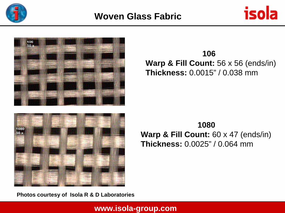
Woven Glass Fabric
106Warp & Fill Count: 56 x 56 (ends/in)Thickness: 0.0015” / 0.038 mm
1080Warp & Fill Count: 60 x 47 (ends/in)Thickness: 0.0025” / 0.064 mm
Photos courtesy of Isola R & D Laboratories

www.isola-group.com
Woven Glass Fabric
1067Warp & Fill Count: 70 x 70 (ends/in)Thickness: 0.0013” / 0.032 mm
1086Warp & Fill Count: 60 x 60 (ends/in)Thickness: 0.002” / 0.050 mm
Photos courtesy of Isola R & D Laboratories

www.isola-group.com
2113Warp & Fill Count: 60 x 56 (ends/in)Thickness: 0.0029” / 0.074 mm
Woven Glass Fabric
Photos courtesy of Isola R & D Laboratories
2313Warp & Fill Count: 60 x 64 (ends/in)Thickness: 0.0032” / 0.080 mm

www.isola-group.com
3070Warp & Fill Count: 70 x 70 (ends/in)Thickness: 0.0034” / 0.086 mm
Woven Glass Fabric
3313Warp & Fill Count: 61 x 62 (ends/in)Thickness: 0.0032” / 0.081 mm
3313 50 x
3070 50 x
Photos courtesy of Isola R & D Laboratories

www.isola-group.com
2116Warp & Fill Count: 60 x 58 (ends/in)Thickness: 0.0038” / 0.097 mm
Woven Glass Fabric
Photos courtesy of Isola R & D Laboratories
1652Warp & Fill Count: 52 x 52 (ends/in)Thickness: 0.0045” / 0.114 mm
www.isola-group.com
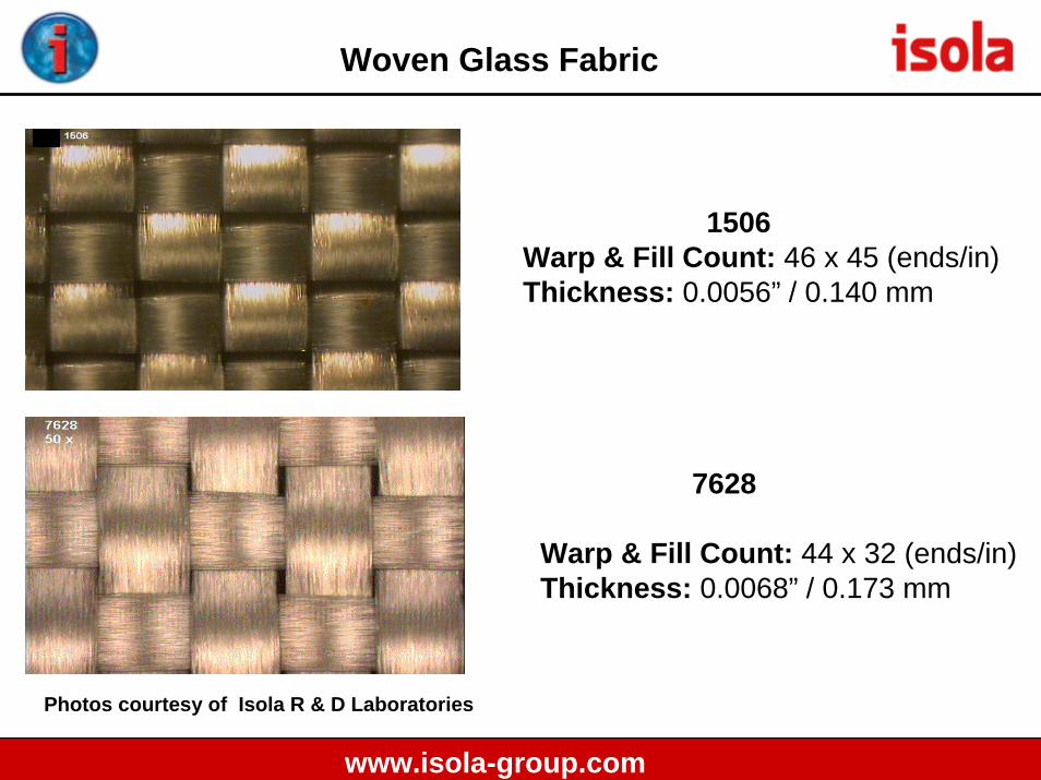
7628
Warp & Fill Count: 44 x 32 (ends/in)Thickness: 0.0068” / 0.173 mm
Woven Glass Fabric
Photos courtesy of Isola R & D Laboratories
1506Warp & Fill Count: 46 x 45 (ends/in)Thickness: 0.0056” / 0.140 mm

www.isola-group.com
North America
106108010671086211333133070211616527628
Asia-Pacific
1061035107810801067108623133313 211615011506 16527628
Europe
10610802113307021161634164716511501216521577628
Isola has Global Std Constructions on the High Performance Materials
Regional Woven Glass Fabric Styles

www.isola-group.com
Sep. plateCopper
2 pliesB-Stage
Copper
Sep. Plate
Multilayer Core Manufacturing

www.isola-group.com
Core/ Construction
0.005” Resin %
1 x 1652 42 %106 / 2113 54 %2 x 1080 56 %1 x 2116 54 %
Positives
Cost/ Thickness/ DSDS/ Std 2 plyLow CostLow Cost
Negatives
Low Resin/ thick glassMost ExpensiveDS/ ThicknessDS/ Thickness
Typical IS415 0.005” Core Constructions
Dk / Df differences based on retained resin %. The difference can be up to 14 %
At 2 GHz Dk on 42 % = 4.12 Df on 42 % = 0.016At 2 GHz Dk on 56 % = 3.79 Df on 56 % = 0.0198
Critical that the right core thickness is used by the OEM/ Designer to meet the impedance criteria.
www.isola-group.com
Grain Direction

www.isola-group.com
Grain Direction
50” wide glass50” x 38” untrimmed48” x 36” trimmedoversized panelsavailable
24”
18”
18”
24”
50” wide Glass - Fill Direction
Grain Directionor Warp Direction

www.isola-group.com
Copper Foil

www.isola-group.com
ED Copper Foil Manufacturing
• Copper is electroplated onto a rotating drum.• Treatments are applied to:
– Micro-roughen surface for adhesion– Plate barrier layer– Coat with anti-tarnish

www.isola-group.com
Copper wt
18 micron = H oz 35 micron = 1 oz70 micron = 2 oz
Heavier copper suchas 3, 4 and 5 oz foil used for power supply designs or ground planes in MLB designs
5 and 6 oz Cu forAutomotive 4 – L designs
12 oz Cu used for Automotive 2 – L designs
Copper Foil Types
ED = standard shiny copper, copper toothHTE = High temp elongation shiny copper, copper toothRTF = reverse treat, low profile copper toothDT = double treat copper, no black oxide needed
The RTF copper foils offer benefits to the fabricator during processing – more defined etched line, ability for thinner lines and lower copper tooth profile.
VLP foils are used for better impedance control
95+ % of NA is RTF foil. Very small percentage = DT
Thicker cores still use some HTE or ED foil.
Copper Foil

www.isola-group.com
Electrodeposited Copper Foil
• ED Foil is “Industry Standard
• Many thicknesses available– ½, 1 and 2 ounce the
most common– 3+ available– 9, 5, 3 micron
Grade Foil Description 1 Standard Electrodeposited 2 High Ductility Electrodeposited 3 High Temperature Elongation
Electrodeposited 4 Annealed Electrodeposited 5 As Rolled-Wrought 6 Light Cold Rolled-Wrought 7 Annealed-Wrought 8 As Rolled-Wrought Low-Temperature
Annealable
Foil
Designator
Common Industry
Terminology
Area Weight (g/m2)
Nominal Thickness
(μm)
Area Weight (oz/ft2)
Area Weight
(g/254 in2)
Nominal Thickness
(mils) E 5 μm 45.1 5.0 0.148 7.4 0.20 Q 9 μm 75.9 9.0 0.249 12.5 0.34 T 12 μm 106.8 12.0 0.350 17.5 0.47 H ½ oz 152.5 17.2 0.500 25.0 0.68 M ¾ oz 228.8 25.7 0.750 37.5 1.01 1 1 oz 305.0 34.3 1 50.0 1.35 2 2 oz 610.0 68.6 2 100.0 2.70 3 3 oz 915.0 103.0 3 150.0 4.05 4 4 oz 1220.0 137.0 4 200.0 5.40 5 5 oz 1525.0 172.0 5 250.0 6.75 6 6 oz 1830.0 206.0 6 300.0 8.10 7 7 oz 2135.0 240.0 7 350.0 9.45
10 10 oz 3050.0 343.0 10 500.0 13.50 14 14 oz 4270.0 480.0 14 700.0 18.90
Foil Profile Type
Max. Foil Profile
(Microns)
Max. Foil Profile (μ Inches)
S – Standard N/A N/A L – Low Profile 10.2 400
V – Very Low Profile 5.1 200 X – No Treatment or
Roughness N/A N/A

www.isola-group.com
Copper Surface Profiles
• Matte Side Surface Profile
Matte Side of Standard Grade 1 Foil Matte Side of Low Profile Grade 1 Foil
LaminateWith Standard
CopperFoil
LaminateWith DSTFoil®CopperFoil
• Standard vs Drum Side Treated Foil ( DSTFoil )

www.isola-group.com
DSTF Process Introduction

www.isola-group.com
DSTFoilDSTFoil®® Comparison to Standard Copper FoilComparison to Standard Copper Foil
DSTFoil®
Standard Copper
DSTF Process Introduction

www.isola-group.com
Standard Foil Clad LaminateStandard Foil Clad Laminate
DSTF Process Introduction
DSTFoil DSTFoil ®® Clad LaminateClad Laminate

www.isola-group.com
Definitions

www.isola-group.com
The Electromagnetic Spectrum employed for RF & Microwave applications
Sho
rtwav
e ra
dio
Mob
ile R
adio
3 MHz 10 MHz30 M
30 MHz
VH
F TV
Beg
ins
FM B
road
cast
Rad
io
100 MHz3 M
HF VHF
Mob
ile R
adio
RF
VH
F TV
Beg
ins
300 MHzU
HF
TV e
nds
Cel
lula
r pho
ne
1 GHz30 cm
GP
S
PCS
3 GHz
Blu
etoo
thW
irele
ss L
AN
UHF
MWMMW
10 GHz3 cm
30 GHz
DBS
Rem
ote
Sens
ing

www.isola-group.com
TG – Glass Transition Temperature; The temperature at which the resin changes from a glass-like state to an amorphous state changing its mechanical behavior, i.e. expansion rate DSC – Differential Scanning Calorimetry; A measurement technique used to characterize the glass transition temperature of a resin by measuring the change in heat given off the resin.
TMA – Thermal Mechanical Analysis; A measurement technique used to characterize the glass transition temperature of a resin by measuring the changing in thermal expansion of a resin as a function of temperature.
DMA – Dynamic Mechanical Testing; A measurement technique used to characterize the glass transition temperature of a resin by measuring the change in modulus of a resin as a function of temperature.
TD – Decomposition Temperature; The temperature at which the resin begins to decompose, measured by a weight change the resin sample.
Definitions

www.isola-group.com
TGA – Thermo-Gravimetric Analysis; A measurement technique used to characterize the decomposition temperature of a resin by measuring the change in weight as a function of temperature.
CTE – Coefficient of Thermal Expansion; The rate of expansion of a laminate as a function of temperature change. Typically reported as PPM/°C or %.
T260 – Time-to-Delamination @ 260°C; A measurement conducted on the TMA apparatus in order to determine a laminate’s resistance to Delamination at 260°C. Delamination is defined as an irreversible expansion in the z-axis. Measurements are noted in minutes at 260°C before failure. T288 – Time-to-Delamination @ 288°C; A measurement conducted on the TMA apparatus in order to determine a laminate’s resistance to Delamination at 288°C. Delamination is defined as an irreversible expansion in the z-axis. Measurements are noted in minutes at 288°C before failure. Dk – Permittivity, Relative Dielectric Constant; The property of a material that impedes the transmission of a electromagnetic wave. The lower the relative dielectric constant, the closer the performance of the material to that of air. This property is critical to matching the impedance requirements of certain transmission lines.
Definitions
www.isola-group.com
Df – Loss Tangent; The property of a material that describes how much of the energy transmitted is absorbed by the material. The greater the loss tangent, the larger the energy absorption into the material. This property directly impacts the signal attenuation at high speeds.
Peel Strength; This measurement is taken to evaluate the adhesion of the resin to the copper cladding, in units of lbf/in or N/m. Measurements are taken after samples have been conditioned in the following manner: as received, after thermal stress, and after chemical processing.
Thermal Stress; This measurement is taken to evaluate the thermal integrity of laminates after short-term exposure to solder, 10 seconds at 550°F (288°C). The samples are evaluated for evidence of blisters and delamination.
Definitions

www.isola-group.com
TCT – Thermal Cycling Test; this type of reliability test is conducted in order to evaluate a PCB’s resistance to plated-thru-hole failures when exposed to repeated temperatures extremes. Factors in this test that vary from OEM-to-OEM include temperature ranges, time at given temperatures, and medium used to heat and cool the PCB (i.e. liquid or air). IST – Interconnect Stress Test; an accelerated thermal cycling test that utilizes DC current to heat the PTH and uses forced air to cool the PTH of a PCB coupon. The benefits of using IST in place of conventional TCT tests include lower cost, failure detection and results within days.
CAF – Conductive Anodic Filament Growth Failure; a PCB reliability issue related to the growth of copper containing filament along the resin-to-glass interface
Definitions

www.isola-group.com
Isola
RoHS
Halogen Free

www.isola-group.com
RoHS Compliancy – Products that are RoHS compliant do not contain the 6 chemical substances listed on the following slide. These substances are not to be used in the base chemistry of laminates or prepregs.
RoHS Compliancy
ALL Isola Products are RoHS Compliant
A RoHS compliant resin system does not mean that it is Lead Free Assembly Compatible at 260 C.

www.isola-group.com
EU RoHS Compliance
Restriction of Hazardous SubstancesLegislation bans the following Six substances for shipment to EU countries effective July 1 -2006
Lead ( Pb )Mercury ( Hg )Hexavalent Chromium ( Cr6+)Polybrominated biphenyl ( PBB )Polybrominated diphenyl ether ( PBDE )
Cadmium ( Cd ) - - Max Conc. By Wt. < 0.01 %
High End Networking companies exempt until 2010 and beyond
Max Conc. By Wt. < 0.1 %