Embed Size (px)
Citation preview
LANCity Cable TV Modem
Device Management
Supports Management Module SM-LCH1000
Titlep
ae
D e v i c e M a n a g e m e n t Page 2 L A N C i t y C a b l e T V M o d e m
Copyright NoticeDocument 9032258-04. Copyright © June 2002 by Aprisma Management Technologies, Inc. All rights reserved worldwide. Use, duplication, or disclosure by the United States government is subject to the restrictions set forth in DFARS 252.227-7013(c)(1)(ii) and FAR 52.227-19.
Liability DisclaimerAprisma Management Technologies, Inc. (“Aprisma”) reserves the right to make changes in specifications and other information contained in this document without prior notice. In all cases, the reader should contact Aprisma to inquire if any changes have been made.
The hardware, firmware, or software described in this manual is subject to change without notice.
IN NO EVENT SHALL APRISMA, ITS EMPLOYEES, OFFICERS, DIRECTORS, AGENTS, OR AFFILIATES BE LIABLE FOR ANY INCIDENTAL, INDIRECT, SPECIAL, OR CONSEQUENTIAL DAMAGES WHATSOEVER (INCLUDING BUT NOT LIMITED TO LOST PROFITS) ARISING OUT OF OR RELATED TO THIS MANUAL OR THE INFORMATION CONTAINED IN IT, EVEN IF APRISMA HAS BEEN ADVISED OF, HAS KNOWN, OR SHOULD HAVE KNOWN, THE POSSIBILITY OF SUCH DAMAGES.
Trademark, Service Mark, and Logo InformationSPECTRUM, IMT, and the SPECTRUM IMT/VNM logo are registered trademarks of Aprisma Management Technologies, Inc., or its affiliates. APRISMA, APRISMA MANAGEMENT TECHNOLOGIES, the APRISMA MANAGEMENT TECHNOLOGIES logo, MANAGE WHAT MATTERS, DCM, VNM, SpectroGRAPH, SpectroSERVER, Inductive Modeling Technology, Device Communications Manager, SPECTRUM Security Manager, and Virtual Network Machine are unregistered trademarks of Aprisma Management Technologies, Inc., or its affiliates. For a complete list of Aprisma trademarks, service marks, and trade names, go tohttp://www.aprisma.com/manuals/trademark-list.htm.All referenced trademarks, service marks, and trade names identified in this document, whether registered or unregistered, are the intellectual property of their respective owners. No rights are granted by Aprisma Management Technologies, Inc., to use such marks, whether by implication, estoppel, or otherwise. If you have comments or concerns
about trademark or copyright references, please send an e-mail to [email protected]; we will do our best to help.
Restricted Rights Notice(Applicable to licenses to the United States government only.)This software and/or user documentation is/are provided with RESTRICTED AND LIMITED RIGHTS. Use, duplication, or disclosure by the government is subject to restrictions as set forth in FAR 52.227-14 (June 1987) Alternate III(g)(3) (June 1987), FAR 52.227-19 (June 1987), or DFARS 52.227-7013(c)(1)(ii) (June 1988), and/or in similar or successor clauses in the FAR or DFARS, or in the DOD or NASA FAR Supplement, as applicable. Contractor/manufacturer is Aprisma Management Technologies, Inc. In the event the government seeks to obtain the software pursuant to standard commercial practice, this software agreement, instead of the noted regulatory clauses, shall control the terms of the government's license.Virus DisclaimerAprisma makes no representations or warranties to the effect that the licensed software is virus-free.
Aprisma has tested its software with current virus-checking technologies. However, because no antivirus system is 100 percent effective, we strongly recommend that you write-protect the licensed software and verify (with an antivirus system in which you have confidence) that the licensed software, prior to installation, is virus-free.
Contact InformationAprisma Management Technologies, Inc.273 Corporate DrivePortsmouth, NH 03801Phone: 603-334-2100U.S. toll-free: 877-468-1448Web site: http://www.aprisma.com
D e v i c e M a n a g e m e n t Page 3 L A N C i t y C a b l e T V M o d e m
ContentsINTRODUCTION 6
Purpose and Scope ........................................................6Required Reading ...........................................................6Supported Devices..........................................................7The SPECTRUM Model ..................................................7
TASKS 10
DEVICE VIEW 11
Interface Device View ...................................................11Interface Icon.............................................................12
Interface Number Label .........................................12IF Status Label.......................................................12Interface Status View .............................................13Interface Threshold View .......................................13Gauge Control Panel .............................................13
Interface Icon Subviews Menu ..................................14Interface Address Translation Table..........................14Secondary Address Panel .........................................14
DEVICE TOPOLOGY VIEW 15
Interface Device Topology View ...................................15
APPLICATION VIEW 16
Supported Applications .................................................17
Common Applications ............................................... 17Device-Specific MIBs ................................................ 18
LCPV210 Application .................................................... 18ASIC Rate Performance View ................................... 19Device Control View .................................................. 20Download View.......................................................... 21Serial EEPROM View................................................ 22Filter Security Group View......................................... 22Software Filtered Frames View ................................. 23Filter Table Control View ........................................... 24Frequency Scan View ............................................... 24Health Parameters View............................................ 25Health Summary View............................................... 25LCN Parameters Control View .................................. 26Receive/Transmit Coefficient Table View.................. 27Sonic Error View........................................................ 28Sonic Rate View ........................................................ 29Sonic Statistics View ................................................. 29Auto Install Statistics View ........................................ 30Miscellaneous Statistics View ................................... 31Modem Control View ................................................. 32
Receive Coefficient Table...................................... 34Transmit Coefficient Table..................................... 34
Unilink Protocol View................................................. 34Block Sync Statistics .......................................... 34Loop Delay Statistics.......................................... 35Pacer Statistics................................................... 35

C o n t e n t s C o n t e n t s
D e v i c e M a n a g e m e n t Page 4 L A N C i t y C a b l e T V M o d e m
Maintenance Summary View.....................................35Block Sync..........................................................36
Performance Summary View.....................................37Ethernet Statistics ..............................................37CATV Statistics ..................................................38CATV Errors .......................................................38
Support History Table................................................38Trap Destination View ...............................................39Trap Type View .........................................................39
LCPV310 Application ....................................................40CATV - Frames View.................................................40CATV - Physical View................................................41CATV - Rates View....................................................42Ethernet View ............................................................43
Ethernet Errors ...................................................43Ethernet Rates ...................................................44
Filter View..................................................................45Etype Filter .........................................................45Filter Selection....................................................45Frames Filter ......................................................46
Health - Green Yellow View.......................................47Health - Yellow Red View..........................................47Health - Low Medium View........................................48Health - Medium High View.......................................48Health - Parameters View..........................................49Health - Summary View.............................................49IP Filter View .............................................................50Parameters View .......................................................50Summary - Maintenance View...................................52Summary - Performance View...................................53
Ethernet ............................................................. 53CATV ................................................................. 54
Support History Log View ......................................... 55Tables - E Type Filter................................................ 55Tables - IP Address Filter ......................................... 56Tables - IP Port Filter ................................................ 57Tables - IP Protocol Filter ......................................... 57Tables - Support History ........................................... 58Tables - Trap Destination.......................................... 58Tables - Trap Type.................................................... 59Unilink Protocol View ................................................ 59
DeBug420App .............................................................. 60ASIC - Buffer Table................................................... 61ASIC - Parameters View........................................... 61
ASIC Parameters............................................... 61Laboratory Debug Information ........................... 62
ASIC - Parameters 2 View........................................ 62ASIC - Statistics Control View................................... 63ASIC - Summary View .............................................. 63ASIC - SW Statistics View ........................................ 64Debug Control View.................................................. 64Dump Control Table.................................................. 65Error Control Table ................................................... 66Filter Table ................................................................ 66Frequency Scan View............................................... 66LCN Parameters View .............................................. 67Modem - Control View .............................................. 67Modem - Control 2 View ........................................... 68Miscellaneous View .................................................. 69See Prom View ......................................................... 70

C o n t e n t s C o n t e n t s
D e v i c e M a n a g e m e n t Page 5 L A N C i t y C a b l e T V M o d e m
Sonic - Information View............................................70Sonic - Buffer Table...................................................71Transmit - Coefficient Table ......................................71Transmit - High Error View ........................................71Transmit - Low Error View .........................................72Transmit - Normal View .............................................73Transmit - Power Table .............................................74Receive - Abnormal View ..........................................74Receive - AGC Table.................................................75Receive - Coefficient Table .......................................75Receive - Error Normal View .....................................75Receive - Normal View ..............................................76Receive - Over Load View.........................................77Unilink Protocol View.................................................78
PERFORMANCE VIEWS 79
Performance View.........................................................80Port Performance View .................................................80LANCity Performance View ..........................................80
CONFIGURATION VIEWS 81
Device Configuration View............................................82IP Information .....................................................82Device Information .............................................82Upgrade Controls ...............................................82
Interface Configuration View.........................................83
MODEL INFORMATION VIEWS 85
INDEX 86
D e v i c e M a n a g e m e n t Page 6 L A N C i t y C a b l e T V M o d e m
Introduction
This section introduces the SPECTRUM Device Management for models of LANCity Cable TV Modems.
This introduction to the Device Management documentation for Nortel LANCity Cable TV Modem devices contains the following information:
• Purpose and Scope• Required Reading• Supported Devices (Page 7)• The SPECTRUM Model (Page 7)
Purpose and ScopeThis document includes information specific to the LANCity Cable TV Modem and the way it is modeled in SPECTRUM. It is intended to be used in conjunction with the SPECTRUM Device Management online documentation. It is important that you have a clear understanding of the functions and navigation techniques of SPECTRUM before using this document. To learn about the functions of SPECTRUM that are not specific to these devices, refer to the Required Reading section that follows. The sections within
this document provide information for monitoring, configuring, and troubleshooting the Nortel LANCity Cable TV Modem.
Required ReadingTo use this document, you should be familiar with the information provided in the documents listed below.
• Getting Started with SPECTRUM for Operators
• Getting Started with SPECTRUM for Administrators
• How to Manage Your Network with SPECTRUM
• SPECTRUM Views• SPECTRUM Menus• SPECTRUM Icons

I n t r o d u c t i o n S u p p o r t e d D e v i c e s
D e v i c e M a n a g e m e n t Page 7 L A N C i t y C a b l e T V M o d e m
Supported DevicesThe LANCity Cable TV Modems act as data links and network layer bridges, preventing unauthorized information into the user premises by transparently bridging Ethernet onto the cable medium. The modems have 2 ports: a cable (coax) port, and an Ethernet AUI port. They can be connected to a router if a routed network is necessary. The LANCity Cable TV Modem supports SNMP for standard network management features.
The modems also support connection throttling (performance on connection can be limited to an operator specified data rate, i.e., a 10-megabit modem could be set to perform at only 1-megabit/sec.), and secure virtual channels between the head end controller and modem.
The following devices are available:
The LCP (Personal Cable Modem) is a cable TV modem which can support up to sixteen users. The LANCity Personal Cable Modem enables the small business or PC user to access a high-speed, city wide cable TV data network.
The LCB (Multiple-User Spanning Tree Cable Modem) is an enterprise network cable TV modem, enabling city wide connectivity of enterprise networks, school systems, and
municipalities at data rates much higher than available via standard telephone modem.
The LCH (Provisioning Server) supports both automatic software upgrades that can be performed over the network and integrated OSS/BSS (Operational System Support/ Business System Support) support.
The LCW (Workgroup Cable Modem) supports up to four users. An Operational Systems Support/Business Systems Support (OSS/BSS) provisioning server ensure easy installation, maintenance, operation, and control.
The SPECTRUM ModelSPECTRUM management modules are software packages that provide templates for creating software models of physical devices and their associated applications. These templates, called model types, specify attributes corresponding to objects defined in the Management Information Bases (MIBs) that govern the operation of the device or application being modeled. Once created, the models reside in the SpectroSERVER database, where they are continually updated with new information obtained by regular polling of the device.
I n t r o d u c t i o n T h e S P E C T R U M M o d e l
D e v i c e M a n a g e m e n t Page 8 L A N C i t y C a b l e T V M o d e m
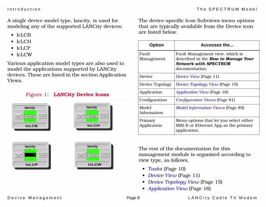
A single device model type, lancity, is used for modeling any of the supported LANCity devices:
• lcLCB • lcLCH• lcLCP • lcLCW
Various application model types are also used to model the applications supported by LANCity devices. These are listed in the section Application Views.
Figure 1: LANCity Device Icons
The device-specific Icon Subviews menu options that are typically available from the Device icon are listed below.
The rest of the documentation for this management module is organized according to view type, as follows.
• Tasks (Page 10)• Device View (Page 11)• Device Topology View (Page 15)• Application View (Page 16)
lancity
lcLCB
lancity
lcLCH
lancity
lcLCP
lancity
lcLCW
Option Accesses the...
Fault Management
Fault Management view, which is described in the How to Manage Your Network with SPECTRUM documentation.
Device Device View (Page 11)
Device Topology Device Topology View (Page 15)
Application Application View (Page 16)
Configuration Configuration Views (Page 81)
Model Information
Model Information Views (Page 85)
Primary Application
Menu options that let you select either MIB-II or Ethernet App as the primary application.
D e v i c e M a n a g e m e n t Page 9 L A N C i t y C a b l e T V M o d e m
• Performance Views (Page 79)• Configuration Views (Page 81)• Model Information Views (Page 85)

D e v i c e M a n a g e m e n t Page 10 L A N C i t y C a b l e T V M o d e m
Tasks
This section lists device management tasks alphabetically and provides links to descriptions of the views and/or tables used to perform the task.
Administrative Status (configure)• IF Status Label (Page 12)• Interface Type Label (Page 12)
CATV - Errors (monitor)• CATV - Frames View (Page 40)
Device (configure)• Interface Device View (Page 11)• Device Configuration View (Page 82)
Device Performance (monitor)• Summary - Performance View (Page 53)• Performance View (Page 80)• Port Performance View (Page 80)
Statistics (monitor)• Interface Device View (Page 11)• Interface Threshold View (Page 13)• CATV - Rates View (Page 42)
• Ethernet View (Page 43)• ASIC - Statistics Control View (Page 63)• Performance Views (Page 79)
Thresholds (monitor, configure)• Health - Green Yellow View (Page 47)• Health - Yellow Red View (Page 47)• Health - Low Medium View (Page 48)• Health - Medium High View (Page 48)
Traps (monitor, configure)• Tables - Trap Destination (Page 58)• Tables - Trap Type (Page 59)• Error Control Table (Page 66)
D e v i c e M a n a g e m e n t Page 11 L A N C i t y C a b l e T V M o d e m
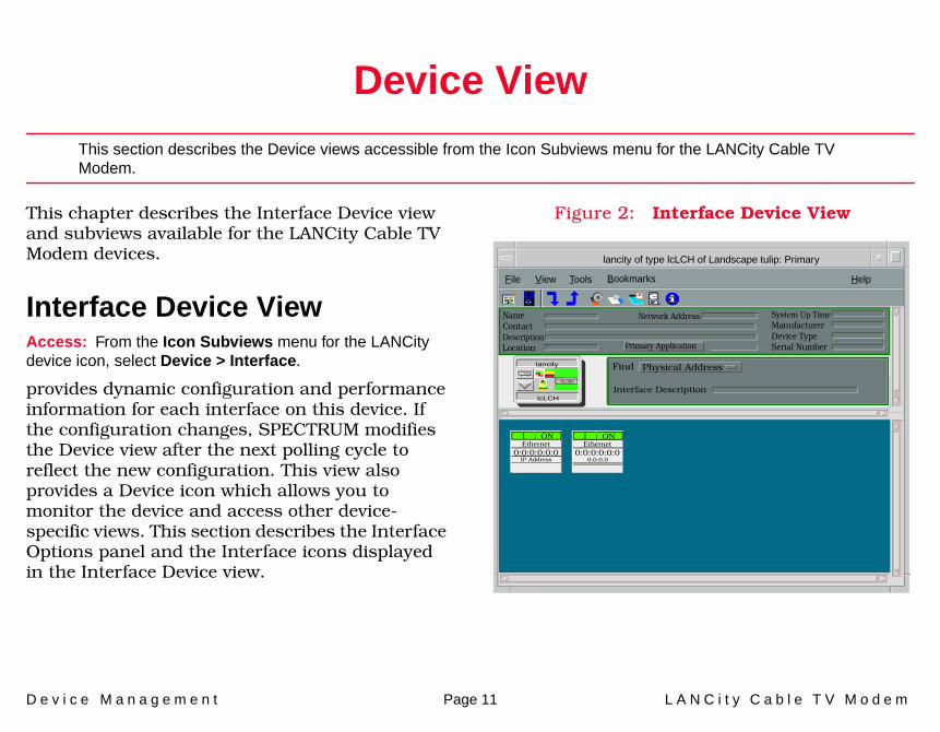
Device View
This section describes the Device views accessible from the Icon Subviews menu for the LANCity Cable TV Modem.
This chapter describes the Interface Device view and subviews available for the LANCity Cable TV Modem devices.
Interface Device ViewAccess: From the Icon Subviews menu for the LANCity device icon, select Device > Interface.
provides dynamic configuration and performance information for each interface on this device. If the configuration changes, SPECTRUM modifies the Device view after the next polling cycle to reflect the new configuration. This view also provides a Device icon which allows you to monitor the device and access other device-specific views. This section describes the Interface Options panel and the Interface icons displayed in the Interface Device view.
Figure 2: Interface Device View
lancity of type lcLCH of Landscape tulip: Primary
File View Help Tools
NameContactDescriptionLocation
System Up TimeManufacturerDevice TypeSerial Number
Network Address
Primary Application
Interface Description
Find Physical Address
Ethernet0:0:0:0:0:0
1 ON
IP Address
lancity
lcLCH
Bookmarks
Ethernet0:0:0:0:0:0
1 ON
0.0.0.0

D e v i c e V i e w I n t e r f a c e D e v i c e V i e w
D e v i c e M a n a g e m e n t Page 12 L A N C i t y C a b l e T V M o d e m
Interface IconFigure 3 shows a closeup of an Interface icon from an Interface Device view. Most of the informational labels on the icon also provide double-click access to other views, as explained in the following label descriptions.
Figure 3: Interface Icon
Interface Number LabelThis label identifies the interface. The number represents the interface number on this device.
IF Status LabelThis label displays the current Operational Status of the interface (see Table 1). Note that the background color of the label also depends on the interface’s current Administrative Status, which is set by the user in the Interface Status View. This view can be accessed by double-clicking the label.
Interface Type LabelThis label identifies the interface type (Ethernet, ATM, etc.). Double-click this label to access the Interface Configuration View (Page 83).
c
f
b
1ethernet
0:0:1D:F:FD:B6
a
a Interface Number Label
b IF Status Label
c Interface Type Label
d Network Type Label
e Physical Address Label
f IP Address Label
fxp0
0.0.0.0
d
e
ON
Table 1: Administrative Status
ColorOperational
StatusAdministrative
Status Label Text
Green ON ON ON
Blue OFF OFF OFF
Yellow OFF ON OFF

D e v i c e V i e w I n t e r f a c e D e v i c e V i e w
D e v i c e M a n a g e m e n t Page 13 L A N C i t y C a b l e T V M o d e m
Interface Status ViewAccess: From the Icon Subviews menu for the Interface icon in the Interface Device view, select IF Status.
The Interface Status view provides the following information on the status of the interface:
Network Type LabelThis label identifies the type of network to which the interface is connected. Double-click the label to open the Model Information view for the interface.
Physical Address LabelThis label displays the physical (MAC) address of the interface. Double-click this label to open the IF Address Translation Table.
IP Address LabelThis label displays the IP address for the interface. Double-click this label to open the Secondary Address Panel (Page 14), which lets you change the address and mask for the interface.
Interface Threshold ViewAccess: From the Icon Subviews menu for the Interface icon in the Interface Device view, select IF Thresholds.
The Interface Threshold view allows a user to set statistical thresholds on a per interface basis with the File > Save All Changes feature.
• Load• Packet Rate• Error Rate• % Discarded
Gauge Control PanelThis panel allows you to change the type of statistical information displayed on the Gauge label of the Interface icon. To access the Gauge Control Panel, double-click the background of the Interface Options panel or Highlight the Interface Options panel and select Icon Subviews > Gauge Control Panel from the View menu. See SPECTRUM Views for detailed information on this panel.
D e v i c e V i e w I n t e r f a c e D e v i c e V i e w
D e v i c e M a n a g e m e n t Page 14 L A N C i t y C a b l e T V M o d e m
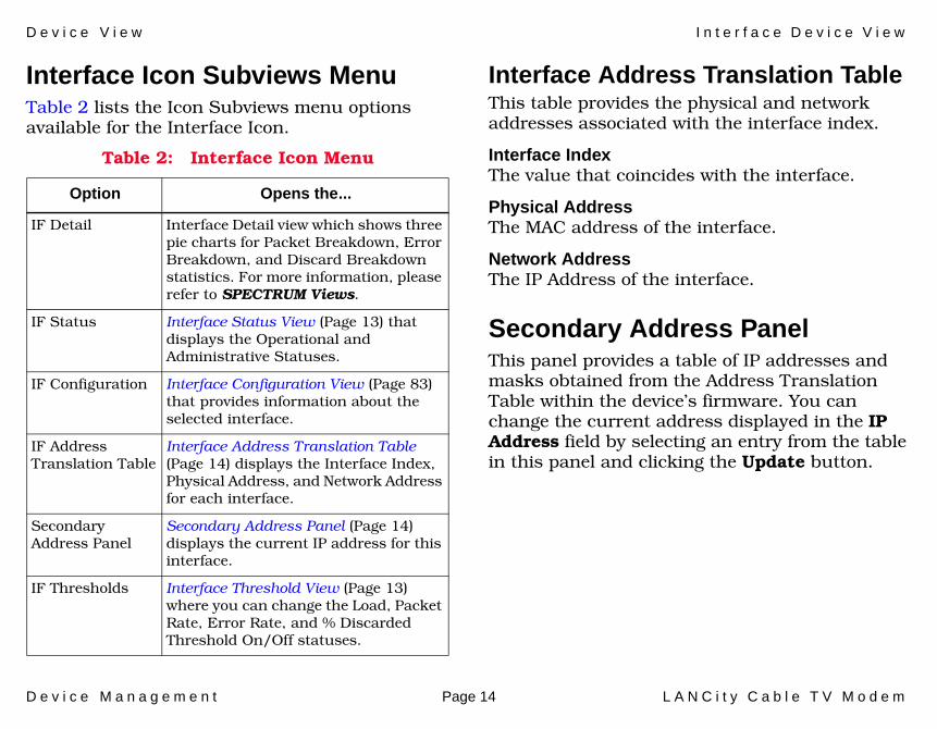
Interface Icon Subviews MenuTable 2 lists the Icon Subviews menu options available for the Interface Icon.
Interface Address Translation TableThis table provides the physical and network addresses associated with the interface index.
Interface IndexThe value that coincides with the interface.
Physical AddressThe MAC address of the interface.
Network AddressThe IP Address of the interface.
Secondary Address PanelThis panel provides a table of IP addresses and masks obtained from the Address Translation Table within the device’s firmware. You can change the current address displayed in the IP Address field by selecting an entry from the table in this panel and clicking the Update button.
Table 2: Interface Icon Menu
Option Opens the...
IF Detail Interface Detail view which shows three pie charts for Packet Breakdown, Error Breakdown, and Discard Breakdown statistics. For more information, please refer to SPECTRUM Views.
IF Status Interface Status View (Page 13) that displays the Operational and Administrative Statuses.
IF Configuration Interface Configuration View (Page 83) that provides information about the selected interface.
IF Address Translation Table
Interface Address Translation Table (Page 14) displays the Interface Index, Physical Address, and Network Address for each interface.
Secondary Address Panel
Secondary Address Panel (Page 14) displays the current IP address for this interface.
IF Thresholds Interface Threshold View (Page 13) where you can change the Load, Packet Rate, Error Rate, and % Discarded Threshold On/Off statuses.
D e v i c e M a n a g e m e n t Page 15 L A N C i t y C a b l e T V M o d e m
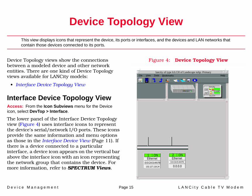
Device Topology View
This view displays icons that represent the device, its ports or interfaces, and the devices and LAN networks that contain those devices connected to its ports.
Device Topology views show the connections between a modeled device and other network entities. There are one kind of Device Topology views available for LANCity models:
• Interface Device Topology View
Interface Device Topology ViewAccess: From the Icon Subviews menu for the Device icon, select DevTop > Interface.
The lower panel of the Interface Device Topology view (Figure 4) uses interface icons to represent the device’s serial/network I/O ports. These icons provide the same information and menu options as those in the Interface Device View (Page 11). If there is a device connected to a particular interface, a device icon appears on the vertical bar above the interface icon with an icon representing the network group that contains the device. For more information, refer to SPECTRUM Views.
Figure 4: Device Topology View
lancity of type lcLCH of Landscape tulip: Primary File View HelpTools
lancity
lcLCH
Ethernet2 ON
0.0.0.00.0.CA:5:44:F9
Ethernet1 ON
0:0:CA:5:44:F8
132.127.118.24
LANCity LCh
Bookmarks
D e v i c e M a n a g e m e n t Page 16 L A N C i t y C a b l e T V M o d e m
Application View
This section describes the main Application view and the associated application-specific subviews available for models of LANCity Cable TV Modems.
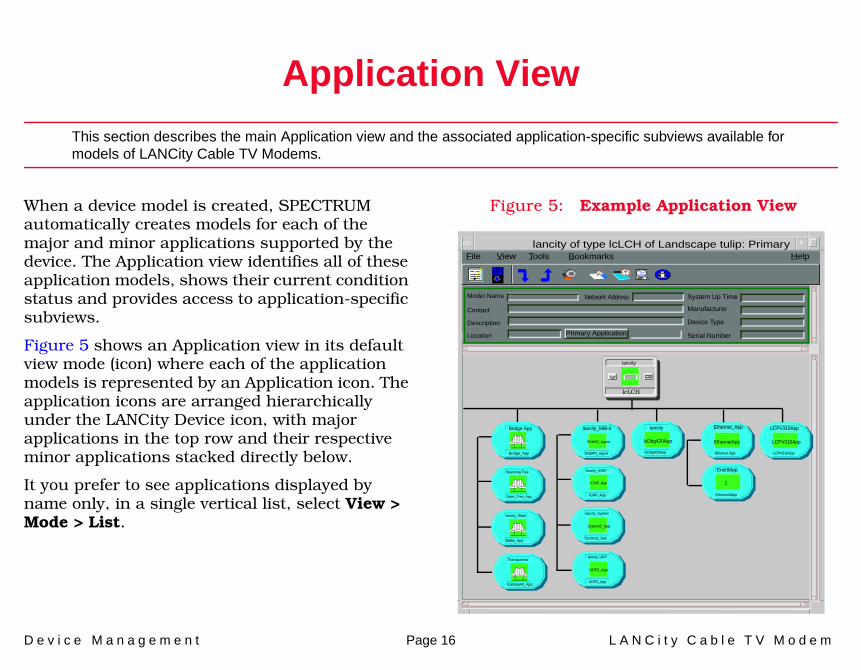
When a device model is created, SPECTRUM automatically creates models for each of the major and minor applications supported by the device. The Application view identifies all of these application models, shows their current condition status and provides access to application-specific subviews.
Figure 5 shows an Application view in its default view mode (icon) where each of the application models is represented by an Application icon. The application icons are arranged hierarchically under the LANCity Device icon, with major applications in the top row and their respective minor applications stacked directly below.
It you prefer to see applications displayed by name only, in a single vertical list, select View > Mode > List.
Figure 5: Example Application View
lancity of type lcLCH of Landscape tulip: Primary
Model Name
Contact
Description
Location Primary Application
System Up Time
Manufacturer
Device Type
Serial Number
Network Address
Bridge App
Bridge_App
Spanning Tree
Span_Tree_App
lancity_Static
Static_App
lcLCH
lancity_MIB-II
SNMP2_Agent
lancity_System
System2_App
lancity_ICMP
ICMP_App
lancity_UDP
UDP2_App
Transparent
transparnt_App
lancity
lcDbg420App
File View Help Tools
UDP2_App
System2_App
ICMP_App
SNMP2_Agent
lancity
lcDbg420App
EnetIfApp
EthernetIfApp
1
LCPV310App
LCPV310App
LCPV310App
Ethernet_App
Ethernet App
EthernetApp
Bookmarks
A p p l i c a t i o n V i e w S u p p o r t e d A p p l i c a t i o n s
D e v i c e M a n a g e m e n t Page 17 L A N C i t y C a b l e T V M o d e m
Supported ApplicationsSPECTRUM’s applications can be grouped within two general categories as follows:
• Applications associated with non proprietary MIBs. See Common Applications below.
• Applications associated with device-specific MIBs. See Device-Specific MIBs (Page 18).
Common ApplicationsFor the most part, these applications represent the non proprietary MIBs supported by your device. Listed below (beneath the title of the SPECTRUM document that describes them) are some of the common applications currently supported by SPECTRUM.
• Routing Applications- Generic Routing- Repeater- AppleTalk- DECnet- OSPF
- OSPF2- BGP4- VRRP
• Bridging Applications- Ethernet Special Database- Spanning Tree- Static- Transparent- PPP Bridging- Source Routing- Translation- QBridge
• MIB II Applications- SNMP- IP- ICMP- TCP- System2- UDP
• Transmission Applications- FDDI- Point to Point- DS1- DS3- RS-232- WAN
Note:Note:
The documents listed below (in bold font) are available for viewing at:
www.aprisma.com/manuals/
A p p l i c a t i o n V i e w L C P V 2 1 0 A p p l i c a t i o n
D e v i c e M a n a g e m e n t Page 18 L A N C i t y C a b l e T V M o d e m
- Frame Relay- Token Ring- Ethernet- Fast Ethernet- rfc1317App- rfc1285App- rfc1315App- 802.11App- SONET
• Technology Applications- APPN- ATM Client- DHCP- PNNI- rfc1316App- DLSw
Device-Specific MIBsSPECTRUM imports the following device-level proprietary MIBs into its database:
• LCPV210-MIB• LCPV310-MIB• LCDebug420-MIB
These MIBs can be used in conjunction with SPECTRUM’s optional customization products (referred to as the Level I Tool Kits) to create
application models and views that display the condition of selected MIB objects.
The following device-specific applications supported by the LANCity Cable TV Modem are described in this section:
• LCPV210 Application (Page 18)• LCPV310 Application (Page 40)• DeBug420App (Page 60)
LCPV210 ApplicationThis major application (model type LCPV210) has the no minor applications. The Icon Subviews menu for this application provides access to the following application-specific subviews:
Note:Note:
Aprisma Management Technologies can provide training, technical assistance, and custom engineering support services for creating application models and their associated views.
Note:Note:
The LCPV210 MIB has been replaced by the LCPV310 MIB. Only older versions of firmware will use the LCPV210 MIB.
A p p l i c a t i o n V i e w L C P V 2 1 0 A p p l i c a t i o n
D e v i c e M a n a g e m e n t Page 19 L A N C i t y C a b l e T V M o d e m
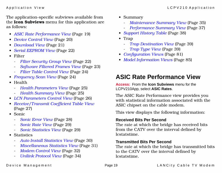
The application-specific subviews available from the Icon Subviews menu for this application are as follows:
• ASIC Rate Performance View (Page 19)• Device Control View (Page 20)• Download View (Page 21)• Serial EEPROM View (Page 22)• Filter
- Filter Security Group View (Page 22)- Software Filtered Frames View (Page 23)- Filter Table Control View (Page 24)
• Frequency Scan View (Page 24)• Health
- Health Parameters View (Page 25)- Health Summary View (Page 25)
• LCN Parameters Control View (Page 26)• Receive/Transmit Coefficient Table View
(Page 27)• Sonic
- Sonic Error View (Page 28)- Sonic Rate View (Page 29)- Sonic Statistics View (Page 29)
• Statistics- Auto Install Statistics View (Page 30)- Miscellaneous Statistics View (Page 31)- Modem Control View (Page 32)- Unilink Protocol View (Page 34)
• Summary- Maintenance Summary View (Page 35)- Performance Summary View (Page 37)
• Support History Table (Page 38)• Trap
- Trap Destination View (Page 39)- Trap Type View (Page 39)
• Configuration Views (Page 81)• Model Information Views (Page 85)
ASIC Rate Performance ViewAccess: From the Icon Subviews menu for the LCPV210App, select ASIC Rates.
The ASIC Rate Performance view provides you with statistical information associated with the ASIC chipset on the cable modem.
This view displays the following information:
Received Bits Per SecondThe rate at which the bridge has received bits from the CATV over the interval defined by lcstatstime.
Transmitted Bits Per SecondThe rate at which the bridge has transmitted bits to the CATV over the interval defined by lcstatstime.
A p p l i c a t i o n V i e w L C P V 2 1 0 A p p l i c a t i o n
D e v i c e M a n a g e m e n t Page 20 L A N C i t y C a b l e T V M o d e m
Packets ReceivedThe rate at which the ASIC has transmitted packets (in packets per second) over the time interval defined by lcstatstime.
Packets TransmittedThe rate at which the ASIC has received packets (in packets per second) over the time interval defined by lcstatstime.
Packets FilteredThe rate at which the ASIC has filtered packets (in packets per second) over the time interval defined by lcstatstime.
Packet CollisionsThe rate at which the ASIC has detected collisions (in collisions per second) over the time interval defined by lcstatstime.
Packets Detected CRCThe rate at which the ASIC has detected CRC errors (in CRC per second) over the time interval defined by lcstatstime.
Packets DeferredThe rate at which the ASIC has deferred transmission (in deferrals per second) over the time interval defined by lcstatstime.
Device Control ViewAccess: From the Icon Subviews menu for the LCPV210App, select Device Control.
This view provides you with selectable or editable fields that allow you to reset the device, enable pacer hello, and write NVRAM contents to flash.
This view displays the following device control information:
Ethernet Devices Supported By Workgroup BridgeThe number of ethernet devices supported by this workgroup bridge.
Ethernet Devices In Filtering DatabaseThe number of ethernet devices in the filtering database.
Snmp AccessThis button determines whether the bridge is “snmpreadonly” or “snmpreadwrite.”
Non-Pacer HelloThis button causes a unit which is NON-pacer to participate in hello exchange.
Pacer HelloThis button causes a unit which is pacer to participate in hello exchange.
Sonic Packets TransmittedThe number of SONIC packets transmitted.
A p p l i c a t i o n V i e w L C P V 2 1 0 A p p l i c a t i o n
D e v i c e M a n a g e m e n t Page 21 L A N C i t y C a b l e T V M o d e m
Sonic Packets ReceivedDisplays the number of SONIC packets received.
ASIC Packets TransmittedThe number of ASIC packets transmitted.
ASIC Packets ReceivedThe number of ASIC packets received.
Transmit Merit LimitThe highest value that can be put on a packet that is transmitted.
Maximum Transmit MeritThe highest value that has been put on a packet that is transmitted.
Receive Merit LimitThe highest value that can be put on a packet that is received.
Maximum Receive MeritThe highest value that has been put on a packet that is received.
Write to FlashThis button allows the NVRAM contents to be written to flash.
Reset DeviceThis button resets the device.
Download ViewAccess: From the Icon Subviews menu for the LCPV210App, select Download.
This view allows you to set the IP Address of a download server, the file name to be downloaded, the protocol of choice for download, and the ability to initiate the download from the SPECTRUM station. This view also shows the current download status.
This view displays the following information:
Load Server IP AddressThe IP Address of the load server for this device.
Gateway IP AddressThe IP Address of the gateway to reach the load server.
Start Down LoadThis button causes the device to request a download from the load server.
Load FileThe load file to request for downloading.
Load ProtocolThis button is used for downloads.
Down Load StatusThe download status for this device.

A p p l i c a t i o n V i e w L C P V 2 1 0 A p p l i c a t i o n
D e v i c e M a n a g e m e n t Page 22 L A N C i t y C a b l e T V M o d e m
Serial EEPROM ViewAccess: From the Icon Subviews menu for the LCPV210App, select Serial EEPROM.
This view displays the following information:
Device Information
• Model• Revision ID• Serial Number• Manufacturing Date
DAC Information
• Trim• Trim Maximum• Trim Minimum
AGC Information
• Threshold• Delay Threshold• Minimum• Maximum• Ring Minimum• Ring Maximum• Delay Minimum• Delay Maximum• Period• Maximum Packet
• Timer• Transmit Power Index• Transmit Power• Receive Power Index• Receive Power
Filter Security Group ViewAccess: From the Icon Subviews menu for the LCPV210App, select Filter > Security Group.
This view provides you with configurable filter security information:
Security Group FilteringThis button determines whether security group filtering is enabled.
Packet Type FilteringThis button determines whether packet type filtering is enabled.
Current Security Group Filtering TypeThis button determines which type of security group filtering is in use for this device.
Current Security GroupThe security group(s) to which this device belongs.
A p p l i c a t i o n V i e w L C P V 2 1 0 A p p l i c a t i o n
D e v i c e M a n a g e m e n t Page 23 L A N C i t y C a b l e T V M o d e m
Broadcast FilteringThis button causes broadcast filtering to be enabled.
Multicast FilteringThis button causes multicast filtering to be enabled.
Packet Type 1-8The 16-bit pattern which will be matched against the ethertype field for received frames.
Software Filtered Frames ViewAccess: From the Icon Subviews menu for the LCPV210App, select Filter > Software Filtered Frames.
This view provides you with ASIC and sonic filter information and the ability to reset software filtering statistics.
This view displays the following information.
ASIC Local LANDisplays the number of frames filtered because source and destination were both on the same side of the bridge (both on CATV) since “power-on.”
ASIC Filtered TypeDisplays the number of frames filtered because the ethertype field of the frame matched one defined to be filtered.
ASIC Filtered Type 1-8The number of frames filtered because the ethertype field of the frame matched packet filter 1 - 8.
SONIC Local LANThe number of frames filtered because source and destination were both on the same side of the bridge (both on ethernet) since power on.
SONIC Filtered TypeThe number of frames filtered because the ethertype field of the frame matched one defined to be filtered.
SONIC Filtered Type 1-8The number of frames filtered because the ethertype field of the frame matched packet filter 1 - 8.
Packets Filtered in a Different Security GroupThe number of frames filtered because they were in a different security group than the bridge.
Reset Software Filtering StatisticsClicking this button resets all software filtering statistics.
A p p l i c a t i o n V i e w L C P V 2 1 0 A p p l i c a t i o n
D e v i c e M a n a g e m e n t Page 24 L A N C i t y C a b l e T V M o d e m
Filter Table Control ViewAccess: From the Icon Subviews menu for the LCPV210App, select Filter > Filter Table Control.
The Filter Table Control view provides you with configurable filter table information:
Current Dynamic EntriesThe number of dynamic entries currently in the filter database.
Max Dynamic Entries AllowedThe maximum number of dynamic entries allowed in the filter database.
Max Dynamic Blocks UsedThe maximum number of dynamic entry blocks used in the filter database.
Current Static EntriesThe number of static entries currently in the filter database.
Max Static Entries AllowedThe maximum number of static entries allowed in the table.
Max TRIE Table Chains DepthThe maximum depth of the TRIE table chains reached.
Frequency Scan ViewAccess: From the Icon Subviews menu for the LCPV210App, select Filter > Frequency Scan.
The Frequency Scan view provides you with complete information on the device being managed.
This view displays the following information:
Starting Rx FrequencyThe starting receiving frequency.
Current Rx FrequencyThe current receiving frequency.
Ending Rx FrequencyThe ending receiving frequency.
Scan IncrementThe scanning increment.
Number of Scans MadeThe number of scans that have been made.
Current Frequency Scan StateThe current frequency scan state.
Assumed Frequency Delta from ChannelThe assumed frequency delta from channel.
A p p l i c a t i o n V i e w L C P V 2 1 0 A p p l i c a t i o n
D e v i c e M a n a g e m e n t Page 25 L A N C i t y C a b l e T V M o d e m
Health Parameters ViewAccess: From the Icon Subviews menu for the LCPV210App, select Health > Health Parameters.
This area of the Health Parameters view displays the health parameters for Green-Yellow, and Yellow-Red thresholds:
• BS Levels Since boot (dbs)• BS Levels Since Block Sync• MAC Packets / MAC Error• Retains BS / Lost BS• Change of Pacer• Ethernet Packet Per Error• LD Levels Min / Max (dbs)• Max Delta between BS & LD
This area of the Health Parameters view displays the health parameters for Low-Moderate, and Moderate-High thresholds:
• Unilink Received• Unilink Transmitted• Unilink Load• Ethernet Received• Ethernet Transmitted• Ethernet Load
Health Summary ViewAccess: From the Icon Subviews menu for the LCPV210App, select Health > Health Summary.
The Health Summary view provides you with at-a-glance color indicators that represent the Ethernet and CATV networks associated with the managed device.
This view displays the following information:
Ethernet Load IndicatorThe Ethernet load indicator.
Ethernet Network LoadThe ethernet network load.
Ethernet Packets Per ErrorThe ethernet packet per error rate.
Ethernet Up IndicatorIndicates that the interface is up.
CATV Load IndicatorThe “unilink” load indicator.
CATV Network LoadThe “unilink” network load.
MAC Packets Per Mac ErrorThe MAC packets for MAC error.
Unilink Up IndicatorIndicates that the interface is up.
A p p l i c a t i o n V i e w L C P V 2 1 0 A p p l i c a t i o n
D e v i c e M a n a g e m e n t Page 26 L A N C i t y C a b l e T V M o d e m
Pacer Change IndicatorThe change of pacer indicator.
Retain/Lost Block SyncThe block synchronization per lost block sync.
Block Sync EstablishedIndicates that block synchronization has been established.
Min/Max Loop Delay Level (dbs)The minimum/maximum loop delay levels in the database.
Max Delta Between Block Sync And Loop DelayThe Max delta between block synchronization and loop delay in database.
Min/Max Block Sync Levels Since Boot UpThe minimum/maximum block synchronization levels since bootup in the database.
Min/Max Block Sync Levels Since Block SyncThe minimum/maximum block synchronization levels since block sync in the database.
LCN Parameters Control ViewAccess: From the Icon Subviews menu for the LCPV210App, select LCN Parameters.
This view provides you with the configuration information set on the LCN server.
This view displays the following information:
Authorized NMS IP AddressThe authorized NMS IP Address.
Authorized NMS MAC AddressThe authorized NMS MAC Address.
Snmp Read OnlySnmp read only.
Install OverrideSkip auto-equalize.
Frequency Scan OverrideThe frequency scan override.
Network Access PriorityThe control variable for Network Access Priority.
Network AccessedIndicates the network accessed.
Max Ethernet NodesThe maximum ethernet nodes.
A p p l i c a t i o n V i e w L C P V 2 1 0 A p p l i c a t i o n
D e v i c e M a n a g e m e n t Page 27 L A N C i t y C a b l e T V M o d e m
Max Bandwidth ReturnedThe maximum bandwidth allowed when transmit onto cable (return path).
Max Bandwidth ForwardedThe maximum bandwidth allowed onto ethernet (from Cable Forward Path).
Max Transmit Burst TypeThe control variable for maximum transmit burst size.
Max CDMDisplays the maximum CDM.
Key IDThe name of the authorization key for authorizing configuration data from the LCN.
Change KeyDisplays the change key.
Working Key IDThe name of the authorization key currently in use for authorizing configuration data from the LCN.
Last Key IDThe name of the previous authorization key for authorizing configuration data from the LCN.
Transmit FrequencyIndicates the transmission frequency.
Receive FrequencyIndicates the receiving frequency.
Headend ReferenceDisplays the headend reference.
Max Loop DelayIndicates the maximum loop delay.
Digest OptionIndicates the digest option.
Min Public Contention %The per cent available for minimum public contention.
Receive/Transmit Coefficient Table ViewAccess: From the Icon Subviews menu for the LCPV210App, select Rx/Tx Coefficient Table.
The RX/TX Coefficient Table provides you with two tables; the Receive Coefficient Table and the Transmit Coefficient Table that list the coefficient indexes and values for those indexes.
This view displays the following information.
Receive Coefficient TableThis area of the RX/TX Coefficient Table provides the following information:
A p p l i c a t i o n V i e w L C P V 2 1 0 A p p l i c a t i o n
D e v i c e M a n a g e m e n t Page 28 L A N C i t y C a b l e T V M o d e m
Index The entry index.
CoefficientDisplays the receive coefficient value.
Transmit Coefficient TableThis area of the RX/TX Coefficient Table provides the following information:
IndexThe entry index.
Imagined CoefficientDisplays the imaginary part of the transmit coefficient.
Real CoefficientDisplays the real part of the transmission coefficient.
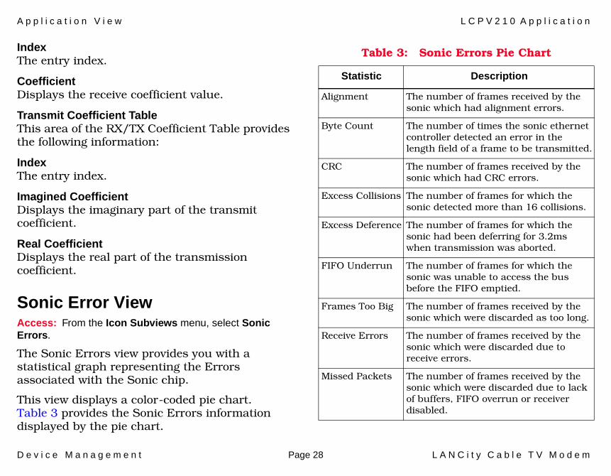
Sonic Error View Access: From the Icon Subviews menu, select Sonic Errors.
The Sonic Errors view provides you with a statistical graph representing the Errors associated with the Sonic chip.
This view displays a color-coded pie chart. Table 3 provides the Sonic Errors information displayed by the pie chart.
Table 3: Sonic Errors Pie Chart
Statistic Description
Alignment The number of frames received by the sonic which had alignment errors.
Byte Count The number of times the sonic ethernet controller detected an error in the length field of a frame to be transmitted.
CRC The number of frames received by the sonic which had CRC errors.
Excess Collisions The number of frames for which the sonic detected more than 16 collisions.
Excess Deference The number of frames for which the sonic had been deferring for 3.2ms when transmission was aborted.
FIFO Underrun The number of frames for which the sonic was unable to access the bus before the FIFO emptied.
Frames Too Big The number of frames received by the sonic which were discarded as too long.
Receive Errors The number of frames received by the sonic which were discarded due to receive errors.
Missed Packets The number of frames received by the sonic which were discarded due to lack of buffers, FIFO overrun or receiver disabled.
A p p l i c a t i o n V i e w L C P V 2 1 0 A p p l i c a t i o n
D e v i c e M a n a g e m e n t Page 29 L A N C i t y C a b l e T V M o d e m
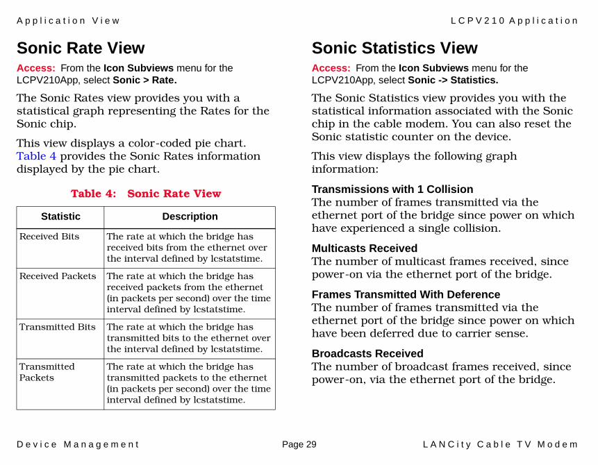
Sonic Rate View Access: From the Icon Subviews menu for the LCPV210App, select Sonic > Rate.
The Sonic Rates view provides you with a statistical graph representing the Rates for the Sonic chip.
This view displays a color-coded pie chart. Table 4 provides the Sonic Rates information displayed by the pie chart.
Sonic Statistics View Access: From the Icon Subviews menu for the LCPV210App, select Sonic -> Statistics.
The Sonic Statistics view provides you with the statistical information associated with the Sonic chip in the cable modem. You can also reset the Sonic statistic counter on the device.
This view displays the following graph information:
Transmissions with 1 CollisionThe number of frames transmitted via the ethernet port of the bridge since power on which have experienced a single collision.
Multicasts ReceivedThe number of multicast frames received, since power-on via the ethernet port of the bridge.
Frames Transmitted With DeferenceThe number of frames transmitted via the ethernet port of the bridge since power on which have been deferred due to carrier sense.
Broadcasts ReceivedThe number of broadcast frames received, since power-on, via the ethernet port of the bridge.
Table 4: Sonic Rate View
Statistic Description
Received Bits The rate at which the bridge has received bits from the ethernet over the interval defined by lcstatstime.
Received Packets The rate at which the bridge has received packets from the ethernet (in packets per second) over the time interval defined by lcstatstime.
Transmitted Bits The rate at which the bridge has transmitted bits to the ethernet over the interval defined by lcstatstime.
Transmitted Packets
The rate at which the bridge has transmitted packets to the ethernet (in packets per second) over the time interval defined by lcstatstime.
A p p l i c a t i o n V i e w L C P V 2 1 0 A p p l i c a t i o n
D e v i c e M a n a g e m e n t Page 30 L A N C i t y C a b l e T V M o d e m
Frames ReceivedThe number of frames received, since power-on, via the ethernet port of the bridge.
Transmissions With Multi-CollisionThe number of frames transmitted via the ethernet port of the bridge since power-on which have experienced multiple collisions.
Frames TransmittedThe number of frames transmitted, since power on, via the ethernet port of the bridge.
Collisions DetectedThe number of collisions detected, since power-on, on the ethernet port of the bridge.
This button opens the Sonic Rate View (Page 29).
This button opens the Sonic Error View (Page 28).
Reset Sonic StatisticsClick on ResetNow to reset all sonic statistics.
Auto Install Statistics ViewAccess: From the Icon Subviews menu for the LCPV210App, select Statistics -> Auto Install.
The Auto Install Statistics view provides you with auto install statistics on LoopDelay, Frequency levels, and Power Levels.
This view displays the following information:
Loop Delay (Bytes)Current loop delay in bytes.
Determine Loop Delay OKAble to determine loop delay counter.
Average Loop Delay PowerThe average loop delay power over 8 power samples in decibel-millivolt.
Min Loop Delay ReceivedThe minimum loop delay received since block sync established in decibel-millivolt.
Max Loop Delay ReceivedThe maximum loop delay received since block sync established in decibel-millivolt.
Current Transmit LevelThe current transmit power level setting in decibel-millivolt.
Sonic Rate
Sonic Errors
A p p l i c a t i o n V i e w L C P V 2 1 0 A p p l i c a t i o n
D e v i c e M a n a g e m e n t Page 31 L A N C i t y C a b l e T V M o d e m
Default Transmit LevelThe default transmit power level setting (in decibel-millivolt).
Levels CalibratedReceive levels valid flag.
Transmit FrequencyIndicates the transmission frequency.
Receive FrequencyIndicates the receiving frequency.
Average Block Sync LevelThe average block sync level since last loop delay average (in decibel-millivolt).
Maximum Received Block SyncThe maximum block sync received since block sync established (in decibel-millivolt).
Minimum Received Block SyncThe minimum block sync received since block sync established (in decibel-millivolt).
Maximum Block Sync Received Since BootThe maximum block sync received since boot.
Minimum Block Sync Received Since BootThe minimum block sync received since boot (in decibel-millivolt).
Receive Equalization MeritReceive equalization figure of merit bigger is better.
Transmit Equalization MeritTransmit equalization figure of merit bigger is better.
Miscellaneous Statistics ViewAccess: From the Icon Subviews menu for the LCPV210App, select Statistics > Miscellaneous.
The Miscellaneous Statics view provides you with miscellaneous statistics and information about the device being managed.
This view displays the following information:
Date and TimeThe date and time in the format mm/dd/yy hh:mm:ss.
No System Buffers AvailableThe number of times a management packet could not be transmitted because no system buffers were available.
Packet Type to CountThe packet type to count.
A p p l i c a t i o n V i e w L C P V 2 1 0 A p p l i c a t i o n
D e v i c e M a n a g e m e n t Page 32 L A N C i t y C a b l e T V M o d e m
ASIC Frames TransmittedIndicates the transmitted done status for non-system frames.
ASIC Frames ReceivedThe frames received from ASIC that were forwarded.
SONIC Frames TransmittedThe number of sonic frames that were transmitted.
SONIC Frames ReceivedThe number of sonic frames that were received.
Modem Control ViewAccess: From the Icon Subviews menu for the LCPV210App, select Statistics > Modem.
The Modem Control view provides you with information and statistics associated with the RF modem interface on the managed device. This information includes: Power levels, BlockSync, Coefficiency, LoopDelay, Pacer Status, and miscellaneous statistics.
This view displays the following information:
Current Transmit Power LevelThe current transmit power level setting.
Default Transmit Power LevelThe default transmit power level setting.
Average Block Sync IF LevelThe average block sync IF level since last LD average.
Average Block Sync RF LevelThe average block sync RF level since last LD average.
Block Sync Receive Level Sample CountThe block synchronization receiving level sample count.
Average Block Sync Demodulator OutputThe average demodulator output level x1000 from block sync packet.
BS Demodulator Output Standard DeviationThe demodulator output standard deviation x1000 from block sync packet.
Average Loop Delay IF LevelThe average loop delay IF over 8 power samples.
Average Loop Delay RF LevelThe average loop delay RF power over 8 power samples.
Loop Delay Receive Level Sample CountThe loop delay receive level sample count.
A p p l i c a t i o n V i e w L C P V 2 1 0 A p p l i c a t i o n
D e v i c e M a n a g e m e n t Page 33 L A N C i t y C a b l e T V M o d e m
Average Loop Delay Demodulator OutputThe average loop demodulator output level x1000 from LD packet.
LD Demodulator Output Standard DeviationDemodulator output standard deviation x1000 from LD packet.
Loop Delay Packets AttemptedDetermines the loop delay packets attempted to send.
Loop Delay Packets ReceivedDetermines the loop delay packets received.
Bad Loop Delay PacketsUnable to determine loop delay counter.
Minimum Loop Delay(BSI)The minimum loop delay in BSI format.
Initial Loop Delay(BSI)The initial loop delay in BSI format.
Maximum Loop Delay(BSI)The maximum loop delay in BSI format.
Transmit Equalization CountTransmit equalization count since last boot.
Receive Equalization CountReceive equalization count since last boot.
Pacer StatusThis field is true when pacer is selected.
Current Block Sync StateThe block synchronization state machine current state.
Periodic Bid StateThe periodic bid state.
Default lcb Transmit CoefficientThe default lcb transmit coefficients.
Default lcb Receive CoefficientThe default lcb receive coefficients.
Default lcp Transmit CoefficientThe default lcp transmit coefficients.
Default lcp Receive CoefficientThe default lcp receive coefficients.
Cable Transmit Byte Limit RolloverTransmit byte limit rollover for cable (1,000,000,000 bytes.)
Ethernet Transmit Byte Limit RolloverTransmit byte limit rollover for ethernet (1,000,000,000 bytes.)
Dedicated Member Add ThresholdThe allocator’s add threshold to become dedicated member.
A p p l i c a t i o n V i e w L C P V 2 1 0 A p p l i c a t i o n
D e v i c e M a n a g e m e n t Page 34 L A N C i t y C a b l e T V M o d e m
Dedicated Member Drop ThresholdThe allocator’s drop threshold to become dedicated member.
Maximum Frame Size for ConcatenationThe maximum size frame, in bytes, for concatenating multiple packets.
Minimum Public Contention Size (slots)The allocator’s minimum public contention size (in slots).
Opens the Receive Coefficient Table (Page 34) and Transmit Coefficient Table (Page 34).
Receive Coefficient TableThis table provides the following information.
IndexThe entry index.
CoefficientDisplays the receive coefficient value.
Transmit Coefficient TableThis table provides the following information:
IndexThe entry index.
Imagined CoefficientDisplays the imaginary part of the transmit coefficient.
Real CoefficientDisplays the real part of the transmit coefficient.
Unilink Protocol ViewAccess: From the Icon Subviews menu for the LCPV210App, select Statistics > Unilink Protocol.
This view provides you with the information associated with Pacer, LoopDelay, and BlockSync. You also have the ability to clear these statistics by selecting the Reset button at the bottom of the view.
Block Sync StatisticsThis area of the Unilink Protocol view provides the following information.
Achieved Block SyncAchieved block synchronization counter.
Block Sync StateBlock sync state machine current state.
Lost Block SyncIndicates the lost block synchronization.
Receive/Transmit Coefficient Table
A p p l i c a t i o n V i e w L C P V 2 1 0 A p p l i c a t i o n
D e v i c e M a n a g e m e n t Page 35 L A N C i t y C a b l e T V M o d e m
Timeout Establishing SyncTimeouts establishing synchronization counter.
Loop Delay StatisticsThis area of the Unilink Protocol view provides the following information.
Loop Delay OkAble to determine loop delay counter.
Loop Delay BadUnable to determine loop delay counter.
Loop Delay (bytes)Unable to determine loop delay counter.
Reset StatisticsReset all unilink protocol statistics.
Pacer StatisticsThis area of the Unilink Protocol view provides the following information.
Lost Pacer Not AllowedLoss of pacer due to “not allowed” counter.
Lost From Block Sync StateLost from block synchronization state.
Excessive Pacer AttemptsNumber of times a unit tried too often to become a pacer.
Timeout From Last NonPacerTimeout from last nonpacer seen.
Losses From No ActivityLoss of pacer due to no activity counter.
Pacer StatusThis is true when pacer is selected.
Last PacerThis is true when we were last pacer.
Pacer AddressDisplays the source address of the current pacer.
Preferred PacerThis is true when preferredPacer is selected. Not true when nonPreferredPacer is selected.
Pacer AllowedThis is true when pacerAllowed is selected. Not true when pacerNotAllowed is selected.
Maintenance Summary ViewAccess: From the Icon Subviews menu for the LCPV210App, select Summary -> Maintenance.
This view provides you with DB levels, Block Synchronization, Error log entries, and Pacer statistics information for the managed device. You can reset these counters by selecting the reset button at the bottom of the view.
A p p l i c a t i o n V i e w L C P V 2 1 0 A p p l i c a t i o n
D e v i c e M a n a g e m e n t Page 36 L A N C i t y C a b l e T V M o d e m
This view displays the following information:
Measured Loop DelayThe loop delay as measured by the bridge.
System Up TimeDisplays the bridge “up-time” from MIB-II.
Bridge ResetsThe number of times the bridge reset.
Delta Levels (Db)This area of the Maintenance Summary view provides the following information:
Max/Min Block Syn To Loop DelayDelta seen between maximum and minimum loop delay levels in the database.
Max/Min Loop DelayDelta seen between maximum and minimum loop delay levels in the database.
Max/Min Rcvd Since BootupDelta seen between maximum and minimum received levels since bootup in the database.
Max/Min Rcvd Since Block SyncDelta seen between maximum and minimum received levels since block sync in the database.
Block SyncThis area of the Maintenance Summary view provides the following information:
Time Out Establishing Block SyncThe number of times a unit timed out trying to establish block sync.
Block Sync LostThe number of times block synchronization was lost by the unit.
Retained/Lost Block SyncRatio of retained block synchronization to lost block sync.
TotalThe number of entries in the field that support history log.
Level 2The number of level 2 entries in the field that support history log.
Level 3The number of level 3 entries in the field that support history log.
Level 4The number of level 4 entries in the field that support history log.
A p p l i c a t i o n V i e w L C P V 2 1 0 A p p l i c a t i o n
D e v i c e M a n a g e m e n t Page 37 L A N C i t y C a b l e T V M o d e m
Excess Pacer AttemptsIndicates the number of times a unit tried too often to become pacer.
Pacer ChangedIndicates the number of times a different pacer was detected.
Maintenance Summary ResetResets all of the “lcpV2MaintSummary” group.
Unilink Down CountThis chart shows the unilink interface down counter.
Ethernet Down CountThis chart shows the ethernet interface down counter.
Performance Summary ViewAccess: From the Icon Subviews menu for the LCPV210App, select Summary -> Performance.
This view provides you with statistical information about the CATV, Ethernet, and Errors associated with the managed device. You can reset these counters by selecting the reset button at the bottom of the view.
Ethernet StatisticsThis area of the Performance Summary view displays Ethernet Statistics, including the following information.
Data Packets Transmitted To EthernetThe number of data packets transmitted to ethernet.
Data Packets Received From EthernetThe number of data packets received from ethernet.
Data Filtered From EthernetIndicates the amount of data filtered from ethernet.
Data Forwarded To Ethernet From CATVIndicates the amount of data forwarded to ethernet from CATV.
Total Transmit/Receive ErrorsIndicates the sum of ethernet errors detected.
Retry PercentageIndicates the percentage of ethernet transmits which were retried.
Packets Processed/ReceivedRatio of packets processed to errors on ethernet.
A p p l i c a t i o n V i e w L C P V 2 1 0 A p p l i c a t i o n
D e v i c e M a n a g e m e n t Page 38 L A N C i t y C a b l e T V M o d e m
CATV StatisticsThis area of the Performance Summary view provides the following information:
Data Packets Transmitted to CATVIndicates the number of data packets that have been transmitted to CATV.
Data Packets Received From CATVIndicates the number of data packets that have been received from CATV.
Data Filtered From CATVIndicates the amount of data filtered from CATV.
Data Filtered To CATV From EthernetIndicates the amount of data filtered to CATV from ethernet.
CATV ErrorsThis area of the Performance Summary view provides the following information.
MAC ErrorsDisplays the number of CATV MAC errors detected.
Retry PercentageIndicates the percentage of CATV transmits which were retried.
MAC Pkts Processed/MAC ErrorsIndicates the ratio of MAC packets processed to MAC errors on CATV.
Performance Summary ResetResets all of the “lcpV2PerfSummary” group.
Support History TableAccess: From the Icon Subviews menu for the LCPV210App, select Support History Table.
This table provides you with the following information.
Next EntryThe next entry to use in the table.
EntryInformation about a specific history entry.
First LogThe time of day the first log entry of this type was created.
Last LogThe time of day the last log entry of this type was created.
Event CountThe number of times this event was repeated consecutively.
A p p l i c a t i o n V i e w L C P V 2 1 0 A p p l i c a t i o n
D e v i c e M a n a g e m e n t Page 39 L A N C i t y C a b l e T V M o d e m
Error LevelIndicates the error level.
Error IDDisplays the error identifier.
Module IDThe module ID calling the error handler.
Trap Destination ViewAccess: From the Icon Subviews menu for the LCPV210App, select Trap > Destination.
This view provides you with a trap table that can be modified (but not added to) by double-clicking on an entry to bring up the Trap Destination IP view.
This view displays the following information.
Trap Destination IndexThe index into the Trap Destination Table.
Trap Destination IPThe IP Address to which the trap will be sent.
Trap Destination StatusControls whether traps are sent to this address.
Trap Type ViewAccess: From the Icon Subviews menu for the LCPV210App, select Trap > Type.
This view provides you with a table listing each trap type and whether it is being sent or not. Each trap type status is configurable by double-clicking on its entry to bring up the Trap Type Status view.
This view displays the following information.
Trap TypeThe index in the Trap Type Table.
Trap StatusControls whether a type of trap is sent.

A p p l i c a t i o n V i e w L C P V 3 1 0 A p p l i c a t i o n
D e v i c e M a n a g e m e n t Page 40 L A N C i t y C a b l e T V M o d e m
LCPV310 ApplicationThis section describes the LCPV310 Application supported by this device. The LCPV310 Application uses LCPV310App as the corresponding model type. This major application provides the following application-specific subviews:
• CATV- CATV - Frames View (Page 40)- CATV - Physical View (Page 41)- CATV - Rates View (Page 42)
• Ethernet View (Page 43)• Filter View (Page 45)• Health
- Health - Green Yellow View (Page 47)- Health - Yellow Red View (Page 47)- Health - Low Medium View (Page 48)- Health - Medium High View (Page 48)- Health - Parameters View (Page 49)- Health - Summary View (Page 49)
• IP Filter View (Page 50)• Parameters View (Page 50)• Summary
- Summary - Maintenance View (Page 52)- Summary - Performance View (Page 53)
• Support History Log View (Page 55)
• Tables- Tables - E Type Filter (Page 55)- Tables - IP Address Filter (Page 56)- Tables - IP Port Filter (Page 57)- Tables - IP Protocol Filter (Page 57)- Tables - Support History (Page 58)- Tables - Trap Destination (Page 58)- Tables - Trap Type (Page 59)
• Unilink Protocol View (Page 59)• Device Configuration View (Page 82)• Model Information Views (Page 85)
CATV - Frames ViewAccess: From the Icon Subviews menu for the LCPV310App, select CATV > Frames.
This view displays the following information:
Dedicated Mode Protocol CRC Errors ReceivedThe number of dedicated mode data frames received by the CATV interface which had CRC errors.
Dedicated Mode Data CRC Errors ReceivedThe number of dedicated mode protocol frames received by the CATV interface which had CRC errors.
A p p l i c a t i o n V i e w L C P V 3 1 0 A p p l i c a t i o n
D e v i c e M a n a g e m e n t Page 41 L A N C i t y C a b l e T V M o d e m
Dedicated Mode Data DiscardedThe number of dedicated mode data frames discarded by the CATV interface due to no buffer being available.
Contention Mode Data CRC Errors ReceivedThe number of contention mode data frames received by the CATV interface which had CRC errors.
Contention Mode Data DiscardedThe number of contention mode data frames discarded by the CATV interface due to no buffer being available.
CATV - Physical ViewAccess: From the Icon Subviews menu for the LCPV310App, select CATV > Physical.
This view displays the following information.
Maintenance Summary ResetWhen a set is performed on this variable, all variables in the Maintenance Summary group are reset.
Transmit Channel PerformanceAn indication of the performance of the channel.
Transmission FrequencyThe device’s transmit frequency in Khz, for the CATV.
Transmission Power Level in DbmvThe default transmit power level setting in Dbmv (decibel millivolts).
Average Received Power Level in DbmvThe average of the last eight values that were obtained when the received power was measured on loop delay packets transmitted by this device in Dbmv.
Performance Summary ResetWhen a set is performed on this variable, all variables in the Performance Summary group are reset.
Receive Channel PerformanceAn indication of the performance of the channel.
Receive FrequencyThe device’s receive frequency, in Khz, for the CATV.
Maximum Received Load in DbmvThe maximum value that was obtained when the received power was measured on a loop delay packet transmitted by this device since the unit has been up in Dbmv (decibel millivolts).
Minimum Received Load in DbmvThe minimum value that was obtained when the receive power was measured on a loop delay
A p p l i c a t i o n V i e w L C P V 3 1 0 A p p l i c a t i o n
D e v i c e M a n a g e m e n t Page 42 L A N C i t y C a b l e T V M o d e m
packet transmitted by this device since the unit has been up (in) Dbmv.
Successful Transmitted and Received Packets to Determine Loop DelayThe total number of times that this device successfully transmitted and received its determine loop delay packets.
Maximum Received Block Sync Since Brought Up in DbmvThe maximum value that was obtained when the power was measured on a block sync packet since the unit has been up (in Dbmv).
Maximum Received Block Sync Since Last Estab-lished in DbmvThe maximum value that was obtained when the power was measured on a block sync packet since block sync was last established (in Dbmv).
Minimum Received Block Sync Since Last Estab-lished in DbmvThe minimum value that was obtained when the power was measured on a block sync packet since block sync was last established (in Dbmv).
Average Block Sync Received Power Level in DbmvThe average of the last eight values that were obtained when the power was measured on block sync packets since block sync was last established (in Dbmv).
Average Received Power Level in Dbmv X 100The current transmit power level in Dbmv multiplied by 100 and returned in integer format.
Current Transmission Power Level in DbmvThe current transmit power level setting (in Dbmv).
Minimum Block Sync Received Power Level in DbmvThe minimum value that was obtained when the power was measured on a block sync packet since the unit has been up (in Dbmv).
CATV - Rates ViewAccess: From the Icon Subviews menu for the LCPV310App, select CATV > Rates.
This view displays the following information.
Received Bits Per SecondThe rate at which data has been received in bits per second from the CATV over the interval of 60 seconds.
Packets Received Per SecondThe rate at which packets have been received from the CATV (in packets per second) over the time interval of 60 seconds.

A p p l i c a t i o n V i e w L C P V 3 1 0 A p p l i c a t i o n
D e v i c e M a n a g e m e n t Page 43 L A N C i t y C a b l e T V M o d e m
Packet Collisions Per SecondThe rate at which collisions have occurred on the CATV (in collisions per second) over the time interval of 60 seconds.
Packets Filtered Per SecondThe rate at which packets have been filtered from the CATV (in packets per second) over the time interval of 60 seconds.
Transmitted Bits Per SecondThe rate at which data has been transmitted in bits per second to the CATV over the interval of 60 seconds.
Packets Transmitted Per SecondThe rate at which packets have been transmitted onto the CATV (in packets per second) over the time interval of 60 seconds.
Packet Deferred Per SecondThe rate at which this device has deferred transmission of its packets onto the CATV over the time interval of 60 seconds.
CRC Errors Per SecondThe rate at which CRC errors have occurred on the CATV (in CRCs per second) over the time interval of 60 seconds.
Ethernet ViewAccess: From the Icon Subviews menu for the LCPV310App, select Ethernet.
Ethernet ErrorsThis area of the Ethernet View displays the errors, including the following information.
Byte Count ErrorsThe number of times the ethernet controller detected an error in the length field of a frame that this device was attempting to transmit.
Excess CollisionsThe number of times the ethernet controller detected that a frame that this device was attempting to transmit had more than 16 collisions.
CRC Error CountThe number of frames received by the ethernet controller which had CRC errors.
Inaccessible Bus CountThe number of times the ethernet controller was unable to access the bus before the FIFO emptied.
Alignment Error CountThe number of frames received by the ethernet controller which had alignment errors.

A p p l i c a t i o n V i e w L C P V 3 1 0 A p p l i c a t i o n
D e v i c e M a n a g e m e n t Page 44 L A N C i t y C a b l e T V M o d e m
Reset Ethernet StatisticsWhen a set is performed on this variable, all ethernet statistics are reset for this device.
Ethernet RatesThis area of the Ethernet View displays the rates, including the following information:
Transmitted Frames CountThe number of frames transmitted onto the ethernet by this device.
Transmitted Frames Collisions CountThe number of transmitted collisions detected on the ethernet port of this device.
Deferred Transmitted Frames CountThe number of frames transmitted onto the ethernet port of this device which have been deferred due to carrier sense.
Received Frames CountThe number of frames received via the ethernet port of this device.
Received Multicast Frames CountThe number of multicast frames received via the ethernet port of this device.
Received Broadcast Frames CountThe number of broadcast frames received via the ethernet port of this device.
Aborted Transmission Frames CountThe number of times the ethernet controller had aborted transmission of a frame after deferring for 3.2ms.
Discarded Exceeded Length Frames CountThe number of frames received by the ethernet interface which were discarded due to their length exceeding 1518 bytes.
Discarded Frames Count By Receive ErrorsThe number of frames received by the ethernet interface which were discarded due to receive errors.
Transmitted Frames Count After a Single CollisionThe number of frames transmitted onto the ethernet port of this device which have experienced a single collision.
Transmitted Frames Count After Multiple CollisionThe number of frames transmitted onto the ethernet port of this device which have experienced multiple collisions.
Discarded Frames Count By Lack of Buffers, FIFO Overrun, or Receiver DisabledThe number of frames received by the ethernet controller which were discarded due to lack of buffers, FIFO (Frames In, Frames Out) overrun, or receiver disabled.
A p p l i c a t i o n V i e w L C P V 3 1 0 A p p l i c a t i o n
D e v i c e M a n a g e m e n t Page 45 L A N C i t y C a b l e T V M o d e m
Transmitted Frames Per SecondThe rate at which this device has transmitted frames onto the ethernet (in frames per second) over the time interval of 60 seconds.
Ethernet Transmitted Bits Per SecondThe rate at which this device has transmitted bits to the ethernet (in bits per second) over the interval of 60 seconds.
Received Frames Per SecondThe rate at which this device has received frames from the ethernet (in frames per second) over the time interval of 60 seconds.
Ethernet Received Bits Per SecondThe rate at which this device has received bits from the ethernet (in bits per second) over the interval of 60 seconds.
Filter ViewAccess: From the Icon Subviews menu for the LCPV310App, select Filter.
Etype FilterThis area of the Filter view displays the “etype” filters, including the following information.
ControlIndicates whether type filtering, specified by the variables in this group and by the Type Filtering Table, is enabled for this device. The variables in this group and entries in the Type Filter Table have no affect if this variable is not set to ON.
NovellIf this variable is set to BLOCK and Control is set to “on”, then all types of Novell traffic will be filtered by this device.
IP Traffic OnlyIf this variable is set to ON and Control is set to “on”, then only IP traffic will be forwarded by this device.
Action Taken If No Match ExistsSpecifies the action that is performed on a packet which does not match any of the entries in the Etype Filter Table.
Filter SelectionThis area of the Filter view displays the general filters, including the following information:
Group FilterSpecifies whether security group filtering is enabled for this device. The Security Group feature allows users that share the same broadband channel to send data to other users in
A p p l i c a t i o n V i e w L C P V 3 1 0 A p p l i c a t i o n
D e v i c e M a n a g e m e n t Page 46 L A N C i t y C a b l e T V M o d e m
the same group without allowing users in other groups to have access to the data. This allows multiple customers to share the same channel but operate as though they were on different networks. Valid values are: on, and off.
Broadcast FilterSpecifies whether MAC layer broadcasts are filtered by this device. Valid values are: on, and off.
Multicast FilterSpecifies whether MAC layer multicasts are filtered by this device. Valid values are: on, and off.
Security Group TypeWhen Group Filter is set to on, this variable specifies whether simple or shared security group filtering is in use by this device. The LANCity device supports two security group types, Simple and Shared.
Device Security GroupSpecifies the security group(s) to which this device belongs.
Filter Spanning Tree MessagesSpecifies whether spanning tree messages are filtered if not in the same security group. The default is OFF, which means that spanning tree messages are not filtered due to security group.
Frames FilterThis area of the Filter view displays the frame filters, including the following information.
Different Security Group Frames Filtered CountThe number of frames filtered because they were sent by a device belonging to a different security group from that which this device belongs.
Frames Filtered Count Residing on the CATV SideThe number of frames filtered because the source and destination devices were both determined to reside on the CATV interface side of this device.
Frames Filtered Count Residing on the Ethernet SideThe number of frames filtered because the source and destination devices were both determined to reside on the ethernet interface side of this device
Reset Software Filtering StatisticsWhen a set is performed on this variable, all software filtering statistics in this group are reset.
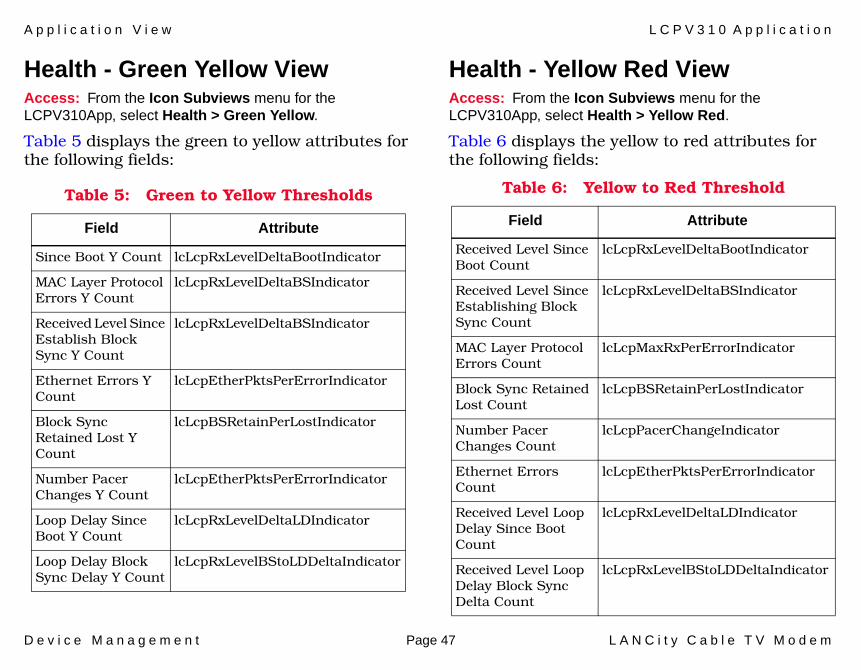
A p p l i c a t i o n V i e w L C P V 3 1 0 A p p l i c a t i o n
D e v i c e M a n a g e m e n t Page 47 L A N C i t y C a b l e T V M o d e m
Health - Green Yellow ViewAccess: From the Icon Subviews menu for the LCPV310App, select Health > Green Yellow.
Table 5 displays the green to yellow attributes for the following fields:
Health - Yellow Red ViewAccess: From the Icon Subviews menu for the LCPV310App, select Health > Yellow Red.
Table 6 displays the yellow to red attributes for the following fields:
Table 5: Green to Yellow Thresholds
Field Attribute
Since Boot Y Count lcLcpRxLevelDeltaBootIndicator
MAC Layer Protocol Errors Y Count
lcLcpRxLevelDeltaBSIndicator
Received Level Since Establish Block Sync Y Count
lcLcpRxLevelDeltaBSIndicator
Ethernet Errors Y Count
lcLcpEtherPktsPerErrorIndicator
Block Sync Retained Lost Y Count
lcLcpBSRetainPerLostIndicator
Number Pacer Changes Y Count
lcLcpEtherPktsPerErrorIndicator
Loop Delay Since Boot Y Count
lcLcpRxLevelDeltaLDIndicator
Loop Delay Block Sync Delay Y Count
lcLcpRxLevelBStoLDDeltaIndicator
Table 6: Yellow to Red Threshold
Field Attribute
Received Level Since Boot Count
lcLcpRxLevelDeltaBootIndicator
Received Level Since Establishing Block Sync Count
lcLcpRxLevelDeltaBSIndicator
MAC Layer Protocol Errors Count
lcLcpMaxRxPerErrorIndicator
Block Sync Retained Lost Count
lcLcpBSRetainPerLostIndicator
Number Pacer Changes Count
lcLcpPacerChangeIndicator
Ethernet Errors Count
lcLcpEtherPktsPerErrorIndicator
Received Level Loop Delay Since Boot Count
lcLcpRxLevelDeltaLDIndicator
Received Level Loop Delay Block Sync Delta Count
lcLcpRxLevelBStoLDDeltaIndicator
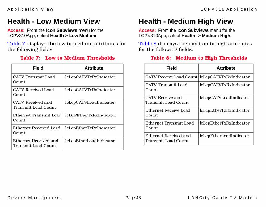
A p p l i c a t i o n V i e w L C P V 3 1 0 A p p l i c a t i o n
D e v i c e M a n a g e m e n t Page 48 L A N C i t y C a b l e T V M o d e m
Health - Low Medium ViewAccess: From the Icon Subviews menu for the LCPV310App, select Health > Low Medium.
Table 7 displays the low to medium attributes for the following fields:
Health - Medium High ViewAccess: From the Icon Subviews menu for the LCPV310App, select Health -> Medium High.
Table 8 displays the medium to high attributes for the following fields:
Table 7: Low to Medium Thresholds
Field Attribute
CATV Transmit Load Count
lcLcpCATVTxRxIndicator
CATV Received Load Count
lcLcpCATVTxRxIndicator
CATV Received and Transmit Load Count
lcLcpCATVLoadIndicator
Ethernet Transmit Load Count
lcLCPEtherTxRxIndicator
Ethernet Received Load Count
lcLcpEtherTxRxIndicator
Ethernet Received and Transmit Load Count
lcLcpEtherLoadIndicator
Table 8: Medium to High Thresholds
Field Attribute
CATV Receive Load Count lcLcpCATVTxRxIndicator
CATV Transmit Load Count
lcLcpCATVTxRxIndicator
CATV Receive and Transmit Load Count
lcLcpCATVLoadIndicator
Ethernet Receive Load Count
lcLcpEtherTxRxIndicator
Ethernet Transmit Load Count
lcLcpEtherTxRxIndicator
Ethernet Received and Transmit Load Count
lcLcpEtherLoadIndicator
A p p l i c a t i o n V i e w L C P V 3 1 0 A p p l i c a t i o n
D e v i c e M a n a g e m e n t Page 49 L A N C i t y C a b l e T V M o d e m
Health - Parameters ViewAccess: From the Icon Subviews menu for the LCPV310App, select Health -> Parameters.
This view displays the following information.
Save All User ThresholdsWhen a set is performed on this variable, the values set by the user for all threshold variables are saved in non-volatile storage. If user values are entered for threshold variables and a set is not performed on this variable, the values will not be retained after a reset or power cycle of the device.
Restore All Threshold DefaultsWhen a set is performed on this variable, the LANCity defaults for all threshold variables are restored.
Health - Summary ViewAccess: From the Icon Subviews menu for the LCPV310App, select Health > Summary.
This view displays the following information.
Block Sync IndicatorThe value of this variable is Green if block synchronization is established, otherwise the value is Red. This indicator is only useful to units which are directly connected to the network
manager via the Ethernet (units connected via UniLINK are not accessible if they have not established block synchronization.)
Received Level Delta Boot IndicatorThis variable is Green if the difference between MinRxBootDbmv and MaxRxBootDbmv is less than or equal to lcLcpRxLevelSinceBootY (the variable which specifies the green to yellow threshold). This variable is Yellow if the difference between MinRxBootDbmv and MaxRxBootDbmv is greater than lcLcpRxLevelSinceBootY and less than or equal to lcLcpRxLevelSinceBootR (the variable which specifies the yellow to red threshold). Otherwise, this variable is Red.
Received Level Delta Block Sync IndicatorThis variable is Green if the difference between MinRxBsDbmv and MaxRxBsDbmv is less than or equal to lcLcpRxLevelSinceEstablishBlockSyncY (the variable which specifies the green to yellow threshold). This variable is Yellow if the difference between MinRxBsDbmv and MaxRxBsDbmv is greater than lcLcpRxLevelSinceEstablishBlockSyncY and less than or equal to LcLcpRxLevelSinceEstablishBlockSyncR (the variable which specifies the yellow to red threshold). Otherwise, this variable is Red.

A p p l i c a t i o n V i e w L C P V 3 1 0 A p p l i c a t i o n
D e v i c e M a n a g e m e n t Page 50 L A N C i t y C a b l e T V M o d e m
IP Filter ViewAccess: From the Icon Subviews menu for the LCPV310App, select IP Filter.
This view displays the following information.
IGMP• Filter Control• Filter Send Destination Unreachable• Filter Count• Reset Filter Counter• Generate SNMP Trap If Detected
Address• Filter Control• Filter Send Destination Unreachable• Action Taken If No Match Exists
Option• Filter Control• Filter Send Destination Unreachable• Filter Count • Reset Filter Counter
Port• Filter Control• Filter Send Destination Unreachable• Action Taken If No Match Exists
Protocol• Filter Control• Filter Send Destination Unreachable• Action Taken If No Match Exists
Parameters ViewAccess: From the Icon Subviews menu for the LCPV310App, select Parameters.
This view displays the following information.
CATV Transmit FrequencyThe device’s transmit frequency for the CATV (in Khz).
CATV Receive FrequencyThe device’s receive frequency for the CATV (in Khz).
Reserved BandwidthThe number of bytes reserved for the guaranteed node.
Network Access PriorityThe device’s priority in accessing the network. High priority specifies guaranteed, collision free access to the network. Low priority specifies contention only access to the CATV bandwidth. Normal priority devices start out with contention only access. Once it detects that it is starting to get busy, the node tries to join the
A p p l i c a t i o n V i e w L C P V 3 1 0 A p p l i c a t i o n
D e v i c e M a n a g e m e n t Page 51 L A N C i t y C a b l e T V M o d e m
reservation mechanism. Once the node becomes idle again, it gives up its right to use reservation.
Access Net PermissionSpecifies whether the device has access to the CATV network. If this variable is 0, then this device cannot receive and transmit data onto the CATV network.
Defer To Guaranteed NodeSpecifies whether this node defers to the network node which is allocated guaranteed bandwidth.
Read OnlyWhen the value of this variable is non-zero, the entire MIB is read-only. Sets cannot be performed on any variables in the MIB.
Device TableThis table contains the IP addresses and MAC addresses configured via the LCN which specify the devices which will be supported on the Ethernet interface of this device.
Maximum Bandwidth ReturnThe amount of data this node is allowed to transmit in bits per second onto the cable’s return channel.
Maximum Transmission BurstThe amount of data a node may transmit onto the cable in a single opportunity.
Maximum Bandwidth ForwardThe amount of data this node is allowed to transmit in bits per second to its local Ethernet (or receives from the cable’s Forward channel).
Minimum Public ContentionThe percent of network bandwidth that is put aside exclusively for contention mode and is not available for reservation mode.
Configured Maximum Round Trip DelayThe configured maximum round trip delay for the network. The value of this variable must be greater than or equal to the loop delay of the LANCity device which is furthest from the headend. All LANCity devices on the HFC segment must have the same value for this variable.
Maximum Number of Supported DevicesThe maximum number of devices supported on the interface.
Headend Reference Node ConfigurationSpecifies whether the device is configured to be a headend reference node. This variable must be set to 0 for LCPs and LCWs.
Data Configuration Authorization KeyThe name specified by the LCN of the authorization key currently in use for authoring configuration data from the LCN.

A p p l i c a t i o n V i e w L C P V 3 1 0 A p p l i c a t i o n
D e v i c e M a n a g e m e n t Page 52 L A N C i t y C a b l e T V M o d e m
Network Management MAC Address AuthorizationWhen this variable is non-zero, it specifies the MAC address of the network management station that is allowed to access the MIB variables supported by this device. If both this variable and lcLcpAuthNmIp are non-zero, then both the MAC address and IP address of packets from a network management station must match.
Network Management IP Address AuthorizationWhen this variable is non-zero, it specifies the IP address of the network management station that is allowed to access the MIB variables supported by this device. If both this variable and lcLcpAuthNmMac are non-zero, then both the MAC address and IP address of packets from a network management station must match.
Number of LANCity Modems Installed on the CATV NetworkThis variable must be set to be greater than or equal to the maximum number of LANCity modems installed on the CATV network.
Previous Data Configuration Authorization KeyThe name of the previous authorization key used for authoring configuration data from the LCN.
Summary - Maintenance ViewAccess: From the Icon Subviews menu for the LCPV310App, select Summary > Maintenance.
This view displays the following information.
Maintenance Summary Reset 2When a set is performed on this variable, all variables in this view are reset.
Received Delta boot in DbmvThe difference between lcLcpMinRxBootDbmv and lcLcpMaxRxBootDbmv.
Received Delta Loop Delay in DbmvThe difference between lcLcpMinRxLdDbmv and lcLcpMaxRxLdDbmv.
Received Delta Block Sync in DbmvThe difference between lcLcpMinRxBsDbmv and lcLcpMaxRxBsDbmv.
Block Sync to Loop Delay Delta in DbmvThe absolute value of the difference between lcLcpAvgBSRxLevelDbmv and lcLcpAvgLDRxLevelDbmv.
Block Sync Retained Per Block Sync LostThe number of times block sync has been lost since the unit has been up.
A p p l i c a t i o n V i e w L C P V 3 1 0 A p p l i c a t i o n
D e v i c e M a n a g e m e n t Page 53 L A N C i t y C a b l e T V M o d e m
Timeout Establishing Block SyncThe number of times the device timed out while trying to establish block synchronization. The timeout for establishing block sync is 10 minutes when the device is first booted. Once the device has established block and loses it, the timeout becomes 2 minutes.
Measured Loop DelayThe value of this device’s loop delay (in bytes).
System Up TimeThe “sysUpTime” from MIB-II. The time (in hundredths of a second) since the network management portion of the system was last re-initialized.
Loss Block SyncThe ratio of the number of times this device retained block sync to the number of times that block sync was lost by the device.
Excess Pacer AttemptsThe number of times that the device exceeded the maximum retries for attempting to become pacer.
Level 2 Log EntriesThe total number of “Level 2” or “Crash” entries logged in the support history log.
Level 3 Log EntriesThe total number of “Level 3” or “Inform” entries logged in the support history log.
Level 4 Log EntriesThe total number of “Level 4” or “Debug” entries logged in the support history log.
Pacer Changed CountThe number of times a different pacer was detected since the unit has been up.
Total Log EntriesThe total number of entries logged in the support history log.
Bridge ResetsThe total number of times that the bridge was reset.
Summary - Performance ViewAccess: From the Icon Subviews menu for the LCPV310App, select Summary - Performance.
EthernetThis area of the Summary - Performance view displays the ethernet statistics, including the following information.

A p p l i c a t i o n V i e w L C P V 3 1 0 A p p l i c a t i o n
D e v i c e M a n a g e m e n t Page 54 L A N C i t y C a b l e T V M o d e m
Frames ForwardedThe number of frames forwarded from the Ethernet to the CATV.
Frames FilteredThe number of frames that were received from the CATV and filtered because the source and destination devices were both determined to reside on the CATV interface side of this device.
Retry PercentageThe percentage of frames transmitted onto the Ethernet which were retried.
Total Errors CountThe total number of transmit and receive errors detected for Ethernet packets by this device.
Packets Per ErrorsThe ratio of the number of packets received by the Ethernet to the number of those packets which had a receive error.
Data Packets ReceivedThe number of data packets received from the Ethernet.
Data Packets TransmittedThe number of data packets transmitted to the Ethernet.
CATVThis area of the Summary - Performance view displays the CATV statistics, including the following information.
Frames ForwardedThe number of frames forwarded from the CATV to the Ethernet.
Frames Filtered The number of frames that were received from the Ethernet and filtered because the source and destination devices were both determined to reside on the Ethernet interface side of this device.
Unilink ErrorsThe number of Unilink protocol packets which had a receive error.
Retry PercentageThe percentage of frames which were transmitted onto the CATV which were retried.
Unilink Packets Per ErrorsThe ratio of the number of Unilink protocol packets processed to the number of Unilink protocol packets which had a receive error.
Data Packets ReceivedThe number of data packets received from the CATV.

A p p l i c a t i o n V i e w L C P V 3 1 0 A p p l i c a t i o n
D e v i c e M a n a g e m e n t Page 55 L A N C i t y C a b l e T V M o d e m
Data Packets TransmittedThe number of data packets transmitted to the CATV.
Support History Log View Access: From the Icon Subviews menu for the LCPV310App, select Support History Log.
This view displays the following information:
Last Entry RecordedThe index of the last entry recorded to the field support history log.
Reset History LogWhen a set is performed on this variable, all data is deleted from the history log and an entry indicating that the log has been reset is logged.
Tables - E Type FilterAccess: From the Icon Subviews menu for the LCPV310App, select Tables > E Type.
This table displays the following information.
IndexThe index of this entry in the Ethertype Filter Table.
StatusSpecifies whether this entry is used for making filtering decisions based on the value of Ethertype, DSAP, or SSAP.
TypeSpecifies whether the value of Value should be compared to the Ethertype, DSAP, or SSAP field in the packet being compared to this entry in the filter table.
ValueSpecifies the value that should be compared to the field in the packet specified by the variable Type.
ActionSpecifies whether a packet is filtered or forwarded when it matches this entry in the filter table.
Match CountThe number of packets which matched this entry in the filter table.
Match Reset CountWhen a set is performed on this variable, the value of Match Count for this entry in the table is set to zero.
A p p l i c a t i o n V i e w L C P V 3 1 0 A p p l i c a t i o n
D e v i c e M a n a g e m e n t Page 56 L A N C i t y C a b l e T V M o d e m
Tables - IP Address FilterAccess: From the Icon Subviews menu for the LCPV310App, select Tables > IP Address Filter.
This table displays the following information.
IndexThe index of this entry in the IP Address Filter Table.
StatusSpecifies whether this entry is used for making filtering decisions based on IP addresses.
InterfaceSpecifies whether a packet received from a particular interface is compared against this entry in order to determine if the packet should be filtered.
Compare IP and Destination IPIf Interface is set to “fromEither” then this address is compared against both the source and destination address to find a match. Otherwise, this address is used to compare against the destination address in the packet.
Compare IP and Destination MaskIf Interface is set to “fromEither” then this mask is used for comparing both the source and destination address to find a match. Otherwise,
this mask is used when comparing against the destination address in the packet.
Compare IP and Source IPIf Interface is set to “fromEither” then this address is compared against both the source and destination address to find a match. Otherwise, it is the address to compare against the source address in the packet.
Compared IP and Source MaskIf Interface is set to “fromEither” then this mask is used for comparing both the source and destination address to find a match. Otherwise, it is the mask used when comparing against the source address in the packet.
ActionSpecifies whether a packet is filtered or forwarded when it matches this entry in the filter table.
CountCounts the number of packets which matched this entry in the filter table.
Reset CountWhen a set is performed on this variable, the value of Count for this entry in the table is set to “zero”.
A p p l i c a t i o n V i e w L C P V 3 1 0 A p p l i c a t i o n
D e v i c e M a n a g e m e n t Page 57 L A N C i t y C a b l e T V M o d e m
Tables - IP Port FilterAccess: From the Icon Subviews menu for the LCPV310App, select Tables - IP Port Filter.
This table displays the following information.
IndexThe index of this entry in the IP Port Filter Table.
StatusSpecifies whether this entry is used for making filtering decisions based on the TCP or UDP port number.
Start PortThe value of the first IP port in a range to use for comparison against the packet.
End PortThe value of the last IP port in a range to use for comparison against the packet.
ActionSpecifies whether a packet is filtered or forwarded when it matches this entry in the filter table.
Match CountThis variable counts the number of packets which matched this entry in the filter table.
Match Reset CountWhen a set is performed on this variable, the value of Match Count for this entry in the table is set to zero.
Tables - IP Protocol FilterAccess: From the Icon Subviews menu for the LCPV310App, select Tables -> IP Protocol Filter.
This table displays the following information.
IndexThe index of this entry in the IP Protocol Filter Table.
StatusSpecifies whether this entry is used for making filtering decisions based on IP protocol.
Start ProtocolThe value of the first IP protocol in a range to use for comparison against the packet.
End ProtocolThe value of the last IP protocol in a range to use for comparison against the packet.
ActionSpecifies whether a packet is filtered or forwarded when it matches this entry in the filter table.
A p p l i c a t i o n V i e w L C P V 3 1 0 A p p l i c a t i o n
D e v i c e M a n a g e m e n t Page 58 L A N C i t y C a b l e T V M o d e m
Match CountCounts the number of packets which matched this entry in the filter table.
Match Reset CountWhen a set is performed on this variable, the value of Match Count for this entry in the table is set to zero.
Tables - Support HistoryAccess: From the Icon Subviews menu for the LCPV310App, select Tables > Support History.
This table displays the following information.
IndexThe index of this entry in the field support history log.
First TimeThe date and time that the first log entry of this type was created.
Last TimeThe date and time that the last log entry of this type was created.
CountThe number of times this event was repeated consecutively.
LevelThe type of entry. A crash level means that the unit encountered a problem for which it must reboot in order to recover. An inform error can specify a normal event or some information regarding an event that is not normally expected.
Error IDAn identifier of the specific event that was logged.
Module IDThe software module responsible for reporting this event.
Parameter CountThe number of parameters that have been logged for this event.
Parameter 1 - 5These variables contain the first through fifth of the parameters logged for this event.
Tables - Trap DestinationAccess: From the Icon Subviews menu for the LCPV310App, select Tables > Trap Destination.
This table displays the following information.
IndexThe index of this entry in the Trap Destination Table.
A p p l i c a t i o n V i e w L C P V 3 1 0 A p p l i c a t i o n
D e v i c e M a n a g e m e n t Page 59 L A N C i t y C a b l e T V M o d e m
StatusThis variable controls whether traps are sent to the destination IP address defined for this entry.
IP AddressThe IP address to which the trap will be sent.
Tables - Trap TypeAccess: From the Icon Subviews menu for the LCPV310App, select Tables > Trap Type.
This table displays the following information:
IndexThe index of this entry in the Trap Type Table.
StatusControls whether this type of trap is generated by this device.
Unilink Protocol ViewAccess: From the Icon Subviews menu for the LCPV310App, select Unilink Protocol.
This table displays the following information.
Network PacerThe network pacer for this protocol.
Pacer AddressThe pacer address for this protocol.
Pacer AllowedIndicates whether or not pacer is allowed. Valid values are: PacerAllowed, and PacerNotAllowed.
Preferred PacerIndicates if the pacer is preferred. Valid values are: PreferredPacer and NonPreferredPacer.
Last Pacer Since Last Block SyncThe last pacer since the last block was synchronized.
Excessive Attempts To Become PacerIndicates how many excessive attempts were made to become pacer.
Lost Block Sync When Trying to be PacerThe lost block synchronized while trying to become pacer.
Lost Pacer Due to no Activity on NetworkThe lost pacer due to no activity on the network.
Lost Block Sync CountThe lost block synchronization count.
Last Packet Sent in Half SecondsThe last packet that was sent in half seconds.
Reset Unilink StatisticsThe reset unilink statistics.
A p p l i c a t i o n V i e w D e B u g 4 2 0 A p p
D e v i c e M a n a g e m e n t Page 60 L A N C i t y C a b l e T V M o d e m
Loop Delay in BytesLoop delay (in bytes).
Achieved Block Sync CountThe achieved block synchronization count.
Block Sync StateThe block synchronization state.
Timeout While Establishing Block SyncThe timeout while establishing block synchronization.
DeBug420AppThis section describes the DeBug420 Application supported by this device. The DeBug420 Application uses DeBug420App as the corresponding model type. This major application provides the following application-specific subviews:
• ASIC- ASIC - Buffer Table (Page 61)- ASIC - Parameters View (Page 61)- ASIC - Parameters 2 View (Page 62)- ASIC - Statistics Control View (Page 63)- ASIC - Summary View (Page 63)- ASIC - SW Statistics View (Page 64)
• Debug Control View (Page 64)• Dump Control Table (Page 65)• Error Control Table (Page 66)• Filter Table (Page 66)• Frequency Scan View (Page 66)• LCN Parameters View (Page 67)• Modem
- Modem - Control View (Page 67)- Modem - Control 2 View (Page 68)
• Miscellaneous View (Page 69)• See Prom View (Page 70)• Sonic
A p p l i c a t i o n V i e w D e B u g 4 2 0 A p p
D e v i c e M a n a g e m e n t Page 61 L A N C i t y C a b l e T V M o d e m
- Sonic - Information View (Page 70)- Sonic - Buffer Table (Page 71)
• Transmit- Transmit - Coefficient Table (Page 71)- Transmit - High Error View (Page 71)- Transmit - Low Error View (Page 72)- Transmit - Normal View (Page 73)- Transmit - Power Table (Page 74)
• Receive- Receive - Abnormal View (Page 74)- Receive - AGC Table (Page 75)- Receive - Coefficient Table (Page 75)- Receive - Error Normal View (Page 75)- Receive - Normal View (Page 76)- Receive - Over Load View (Page 77)
• Unilink Protocol View (Page 78)• Model Information Views (Page 85)
ASIC - Buffer TableAccess: From the Icon Subviews menu for the DeBugApp, select ASIC -> Buffer Table.
This table displays the following information.
ASIC Buffer Index The index for the ASICs - Buffer Table.
ASIC Buffer AddressThe ASIC buffer address.
ASIC - Parameters ViewAccess: From the Icon Subviews menu for the DeBugApp, select ASIC > Parameters.
ASIC ParametersThis area of the ASIC - Parameters view displays the ASIC parameters, including the following information.
Slot SizeBytes per slot from last block sync packet.
Block Synchronize IntegerSlots per bsi from last block synchronization packet.
Maximum Concatenation SizeThe maximum size frame which the ASIC will concatenate packets into.
Public ContentionThe time within the block synchronization interval reserved for public contention access.
Allocator DelayThe number of slots that “delay” required by the allocator.
Allocator Maximum ProcessThe number of slots that “delay” required by the allocator.
A p p l i c a t i o n V i e w D e B u g 4 2 0 A p p
D e v i c e M a n a g e m e n t Page 62 L A N C i t y C a b l e T V M o d e m
Laboratory Debug InformationThis area of the ASIC - Parameters view displays the debug information, including the following:
MemberWhether the user is a member.
Response AgreesIndicates the response was seen and agrees.
Server Missed ResponsesThe response does not agree or the server missed the response.
Ask For MembershipTransmit asks for membership.
Queue HighTransmit any high queue.
Setup Bid Loop DelayTransmit initial bid loop delay.
Setup Period Loop DelayTransmit periodic loop delay.
Setup Next RequestIndicates the next setup request.
Setup Next ResponseIndicates the next setup response.
Member False M2/M1/P1/P2/P3/P4/P5/P7/P8
ASIC - Parameters 2 ViewAccess: From the Icon Subviews menu for the DeBugApp, select ASIC > Parameters 2.
This view displays the following information.
Member False OtherMembership false - other.
Requested Bandwidth CountThe number of times bandwidth was requested.
No Requested Bandwidth CountThe number of times no requested bandwidth.
RBA1 Break CountThe end of RBA during response process.
RBA2 Break CountIndicates the next pointer during response processing.
Accumulation RequestThe accumulated number of requests.
Thresh Packet TotalThe threshold packet total.
Total RequestsThe total number of requests.
Total Non-Null RequestsThe total number of non-null requests.
A p p l i c a t i o n V i e w D e B u g 4 2 0 A p p
D e v i c e M a n a g e m e n t Page 63 L A N C i t y C a b l e T V M o d e m
Bandwidth MissedNumber of times requested bandwidth and did not receive it.
Never Saw Our Own RequestIndicates that our own request was not seen or acknowledged.
Unable To Grant RequestUnable to grant request, insufficient dedicated bandwidth.
Response1 Break Count (Response2,3,4)
No Bandwidth
Revid CounterRevid counter for condition where allocator was delayed processing request and new patch is executed.
TXOP SavedTXOP table was updated but not restored before processing next response.
TXOP Saved 2TXOP table was updated but not restored before setting up loop delay start in maintenance area.
Response Members
Asked
Asked Next
ASIC - Statistics Control ViewAccess: From the Icon Subviews menu for the DeBugApp, select ASIC > Statistics Control.
This view displays the following information.
Reset ASIC Statistics Selecting this will reset all ASIC statistics.
ASIC - Summary ViewAccess: From the Icon Subviews menu for the DeBugApp, select ASIC > Summary.
This view displays the following information:
Non Unilink TransmittedTotal non unilink packets transmitted.
Unilink TransmittedTotal unilink packets transmitted.
Non Unilink RetryNumber of non unilink transmitted packets retried due to errors.
Non Unilink ReceivedTotal non unilink packets received.
Unilink ReceivedTotal unilink packets received.
A p p l i c a t i o n V i e w D e B u g 4 2 0 A p p
D e v i c e M a n a g e m e n t Page 64 L A N C i t y C a b l e T V M o d e m
Low CRC ErrorsNumber of packets received on low queue with CRC errors.
High MAC CRC ErrorsNumber of packets received on High and MAC queues with CRC errors.
Collisions ReceivedNumber of packets received with collisions.
ASIC - SW Statistics ViewAccess: From the Icon Subviews menu for the DeBugApp, select ASIC > SW Statistics.
This view displays the following statistics:
• Transmit Bad Low Q• Determine Loop Delay Packets• High Transmit Packets• Transmit Good High Q• Transmit Bad High Q• Received Good High Q• Block Synchronize Packets• MAC Transmit Packets• Transmit Good MAC Q• Transmit Bad MAC Q• Receive Good MAC Q• Receive Loop Delay Packets
• Receive Blocks Timestamp• Receive Blocks Timestamp Drop• Receive Blocks Timestamp Snap• Receive Exception Error Count• Transmit Exception Error Count• Block Boundary Expired Count• ASIC Timer Expired Count• Reset ASIC S/W Statistics• Reset All ASIC S/W Statistics• ASIC Multicast Frames Received
Debug Control ViewAccess: From the Icon Subviews menu for the DeBugApp, select Debug Control.
This view displays the following information.
Received ASIC Packet TotalTotal number of received ASIC packet buffers that were skipped except for the all skipped condition.
Transmitted ASIC Packet TotalTotal number of transmitted ASIC packet buffers that were skipped except for the all skipped condition.
A p p l i c a t i o n V i e w D e B u g 4 2 0 A p p
D e v i c e M a n a g e m e n t Page 65 L A N C i t y C a b l e T V M o d e m
Received SONIC Packet TotalTotal number of received SONIC packet buffers that were skipped except for the all skipped condition.
Transmitted SONIC Packet TotalTotal number of transmitted SONIC packet buffers that were skipped except for the all skipped condition.
Transmit Merit MaximumTotal number of transmitted merit maximum buffers that were skipped except for the all skipped condition.
Transmit Merit LimitTotal number of transmitted merit limit buffers that were skipped except for the all skipped condition
Received Merit MaximumTotal number of received merit maximum buffers that were skipped except for the all skipped condition.
Received Merit LimitTotal number of received merit limit buffers that were skipped except for the all skipped condition
Pacer HelloSet this field to On causes a unit to participate in hello exchange or Off do not participate in hello exchange.
Non Pacer HelloSet this field to On a unit which is non-pacer to participate in hello exchange or Off a unit which is non-pacer to not participate in hello exchange.
Dump Control TableAccess: From the Icon Subviews menu for the DeBugApp, select Dump Control Table.
This table displays the following information.
Index The index into the Dump Control Table.
StartThe beginning address of the memory to dump.
LengthThe length of the memory to dump.
A p p l i c a t i o n V i e w D e B u g 4 2 0 A p p
D e v i c e M a n a g e m e n t Page 66 L A N C i t y C a b l e T V M o d e m
Error Control TableAccess: From the Icon Subviews menu for the DeBugApp, select Error Control Table.
This table displays the following information.
ECT Error LevelThe index into the Error Control Table.
LogSet this field to On to log an error in the history support log, or setting this to Off does not log an error in the history support log.
Trap Set this field to On to send a trap when this error occurs, or setting this to Off does not send a trap when this error occurs.
DumpSet this field to Onto dump memory when this error occurs, or setting this to Off does not dump memory when this error occurs.
ResetSet this field to On to reset when this error occurs, or setting this to Off does not reset when this error occurs.
Filter Table Access: From the Icon Subviews menu for the DeBugApp, select Filter.
This table displays the following information.
Dynamic Blocks UsedThe maximum number of dynamic entry blocks ever used in the filter.
Maximum Chain DepthThe maximum depth the TRIE table chains reaches.
Frequency Scan ViewAccess: From the Icon Subviews menu for the DeBugApp, select Frequency Scan.
This view displays the following information.
Starting Receiving FrequencyThe starting received frequency.
Current Receiving FrequencyThe current received frequency.
Ending Receiving FrequencyThe ending received frequency.
Scanning IncrementThe scanning increment.
A p p l i c a t i o n V i e w D e B u g 4 2 0 A p p
D e v i c e M a n a g e m e n t Page 67 L A N C i t y C a b l e T V M o d e m
Scanning CountThe number of scans made.
Assumed Frequency DeltaThe assumed frequency delta from channel.
Current Frequency Scan StateThe current frequency scan state.
LCN Parameters ViewAccess: From the Icon Subviews menu for the DeBugApp, select LCN Parameters.
This view displays the following information.
• Digest Option• Change Key• Key Id• Frequency Scan Override• Install Override• LCN Less Enabled
Modem - Control ViewAccess: From the Icon Subviews menu for the DeBugApp, select Modem -> Control.
This view displays the following information.
Current Transmit Power LevelThe current transmit power level setting.
Default Transmit Power LevelThe default transmit power level setting.
Average Block Synch IF LevelThe average block sync IF level since last LD average.
Average Block Synch RF LevelThe average block sync RF level since last LD average.
Block Synch Rx Sample CountThe block sync received level sample count.
Average Loop Delay IF Rx LevelThe average loop delay IF over 8 power samples.
Average Loop Delay RF Rx LevelThe average loop delay RF power over 8 power samples.
Loop Delay Rx Level Sample CountThe loop delay received level sample count.

A p p l i c a t i o n V i e w D e B u g 4 2 0 A p p
D e v i c e M a n a g e m e n t Page 68 L A N C i t y C a b l e T V M o d e m
Loop Delay Packets AttemptedThe determine loop delay packets attempted.
Loop Delay Packets ReceivedThe receive determine loop delay packets.
Undetermined Loop Delay CountUnable to determine loop delay counter.
Minimum Loop DelayThe minimum loop delay when known in BSI format.
Initial Loop DelayThe initial loop delay when known in BSI format.
Maximum Loop DelayThe maximum loop delay when known in BSI format.
Average Demodulator OutputThe average demodulator output level x1000 from ld packet.
Demodulator Output Std DeviationThe demodulator output standard deviation x1000 from ld packet.
Modem - Control 2 ViewAccess: From the Icon Subviews menu for the DeBugApp, select Modem > Control 2.
This view displays the following information.
Transmit Equalization CountThe transmitted equalization count since last boot.
Receive Equalization MeanThe average demodulator output level x1000 from bs packet.
Receive Equalization Std DeviationThe demodulator output standard deviation x1000 from bs packet.
Receive Equalization CountThe received equalization count since last boot.
BidstateThe periodic bid state.
CATV Limit RolloverThe transmitted byte limit rollover for cable (1,000,000,000 bytes).
Ethernet Limit RolloverThe transmitted byte limit rollover for ethernet (1,000,000,000 bytes).
A p p l i c a t i o n V i e w D e B u g 4 2 0 A p p
D e v i c e M a n a g e m e n t Page 69 L A N C i t y C a b l e T V M o d e m
Add ThresholdThe allocator’s add threshold to become a dedicated member.
Drop Threshold The allocator’s drop threshold to become a dedicated member.
Maximum ConcatenationThe maximum size frame in bytes for concatenating multiple packets.
Minimum Public Contention SizeThe allocator’s minimum public contention size in slots.
Receive LCB Coefficient CountThe default lcb received coefficients.
Receive LCP Coefficient CountThe default lcp received coefficients.
Transmit LCB Coefficient CountThe default lcb transmitted coefficients.
Transmit LCP Coefficient CountThe default lcp transmitted coefficients.
HRN Equalization EnabledSpecifies if the HRN equalization is enabled. Valid values are: on, off.
Miscellaneous ViewAccess: From the Icon Subviews menu for the DeBugApp, select Miscellaneous.
This view displays the following information.
No System Buffers Unable To TransferThe number of times a management packet could not be transmitted because system buffers weren’t available.
Packet Type To CountThe number of packet types to be counted.
Data SONIC Frames ReceiveThe number of data SONIC frames that have been received.
Data ASIC Frames TransmitThe transmit done status for non-system frames.
Data ASIC Frames ReceiveThe frames received from ASIC that were forwarded.
Data SONIC Frames TransmitThe number of data SONIC frames that have been transmitted.
No ASIC TDAA read/write counter displaying the number of ASIC TDA.

A p p l i c a t i o n V i e w D e B u g 4 2 0 A p p
D e v i c e M a n a g e m e n t Page 70 L A N C i t y C a b l e T V M o d e m
No SONIC TDAA read/write counter displaying the number of SONIC TDA.
See Prom ViewAccess: From the Icon Subviews menu for the DeBugApp, select See Prom.
This view displays the following information:
• Pagc Threshold• Pagc Delay Threshold• Pagc Minimum• Pagc Maximum• Pagc Range Minimum• Pagc Range Maximum• Pagc Delay Minimum• Pagc Delay Maximum• Pagc Period• Pagc Maximum Packet• Pagc Timer• Transmit DAC Trim• Transmit DAC Trim Maximum• Transmit DAC Trim Minimum
Sonic - Information ViewAccess: From the Icon Subviews menu for the DeBugApp, select Sonic > Information.
This view displays the following information.
FIFO OverrunThe FIFO overrun interrupt status bit set.
Buffer Area ExceededThe buffer area exceeded interrupt status bit set.
Buffers ExhaustedThe buffers exhausted interrupt status bit set.
Receive Descriptors ExhaustedThe receive descriptors exhausted interrupt status bit set.
Heartbeat LostThe heartbeat lost interrupt status bit set.
Bus RetryThe bus retry interrupt status bit set.
Data Path Sonic RRA OutThe data path detected all buffers skipped condition.
Data Path Sonic Buffer SkipThe data path detected when a buffer was skipped.
A p p l i c a t i o n V i e w D e B u g 4 2 0 A p p
D e v i c e M a n a g e m e n t Page 71 L A N C i t y C a b l e T V M o d e m
Data Pathtotal Buffers SkippedThe total number of buffers that were skipped except for the all skipped condition.
Sonic - Buffer TableAccess: From the Icon Subviews menu for the DeBugApp, select Sonic > Buffer Table.
This table displays the following information.
Sonic Buffer Index The entry index for the Sonic - Buffer Table.
Sonic Buffer AddressThe sonic buffer address.
Transmit - Coefficient TableAccess: From the Icon Subviews menu for the DeBugApp, select Transmit > Coefficient Table.
This table will display the following information.
IndexThe entry index for the Transmit Coefficient Table.
Real The real part of the transmit coefficient.
ImaginaryThe imaginary part of the transmit coefficient.
Transmit - High Error ViewAccess: From the Icon Subviews menu for the DeBugApp, select Transmit > High Error.
This view displays the following information.
Con Retry CountRetry count - cumulative number of retries.
Con DeferredDeferred packet - incremental once if packet was deferred for any slots.
Con Retry OnceRetry equal one - incremental once if retry count equals one.
Con Retry MultipleRetry multiple - incremental once if retry count is greater than one.
Ded Retry CountRetry count - cumulative number of retries.
Ded DeferredDeferred packet - incremental once if packet was deferred for any slots.
Ded Retry OnceRetry equal one - incremental once if retry count equals one.
A p p l i c a t i o n V i e w D e B u g 4 2 0 A p p
D e v i c e M a n a g e m e n t Page 72 L A N C i t y C a b l e T V M o d e m
Ded Retry MultipleRetry multiple - incremental once if retry count is greater than one.
Transmit - Low Error ViewAccess: From the Icon Subviews menu for the DeBugApp, select Transmit -> Low Error.
This view displays the following information.
Con Single Retry CountThe retry count - cumulative number of retries.
Con Single DeferredThe deferred packet count, which is incremented once if packet was deferred for any slots.
Con Single Retry OnceThe retry equal one - incremented once if retry count equals one.
Con Single Retry MultipleThe retry multiple - incremented once if retry count is greater than one.
Con Concatenation Retry CountThe retry count cumulative number of concatenation retries.
Con Concatenation DeferredThe deferred packet incremented once if packet was deferred for any slots.
Con Concatenation Retry OnceThe retry equal one - incremented once if retry count equals one.
Con Concatenation Retry MultipleThe retry multiple - incremented once if retry count is greater than one.
Ded Single Retry CountThe retry count - cumulative number of retries.
Ded Single DeferredThe deferred packet incremented once if packet was deferred for any slots.
Ded Single Retry OnceThe retry equal one - incremented once if retry count equals one.
Ded Single Retry MultipleThe retry multiple - incremented once if retry count is greater than one.
Ded Concatenation Retry CountThe retry count cumulative number of concatenation retries.
Ded Concatenation DeferredThe deferred packet incremented once if packet was deferred for any slots.
A p p l i c a t i o n V i e w D e B u g 4 2 0 A p p
D e v i c e M a n a g e m e n t Page 73 L A N C i t y C a b l e T V M o d e m
Ded Concatenation Retry OnceThe retry equal one - incremented once if retry count equals one.
Ded Concatenation Retry MultipleThe retry multiple - incremented once if retry count is greater than one.
Transmit - Normal ViewAccess: From the Icon Subviews menu for the DeBugApp, select Transmit > Normal.
This view displays the following information.
Low Con Single PacketsPackets transmitted - incremented once for each packet.
Low Con Single FramesFrames transmitted - incremented once for each packet.
Low Con Concatenation PacketsPackets transmitted - incremented once for each packet.
Low Con Concatenation FramesFrames transmitted - incremented once for each packet.
Low PendingTransmit low pending - incremented once per slot not used.
Low Ded Single Packets Packets transmitted - incremental once for each packet.
Low Ded Single FramesFrames transmitted - incremented once for each packet.
High PendingTransmit high pending - incremented once per slot not used.
Low Ded Concatenation Packets Packets transmitted - incremented once for each packet.
Low Ded Concatenation FramesFrames transmitted - incremented once for each packet.
Transmit Low High PendingTransmit low and high pending - incremented once per slot not used.
High Con PacketsPackets transmitted - incremented once for each packet.
A p p l i c a t i o n V i e w D e B u g 4 2 0 A p p
D e v i c e M a n a g e m e n t Page 74 L A N C i t y C a b l e T V M o d e m
High Con FramesFrames transmitted - incremented once for each packet.
High Ded Packets Packets transmitted - incremented once for each packet.
High Ded FramesFrames transmitted - incremented once for each packet.
Transmit - Power TableAccess: From the Icon Subviews menu for the DeBugApp, select Transmit > Power.
This view displays the following information.
Transmit PowerThe transmission power for the given index.
IndexDisplays the entry index to the Power Table.
Receive - Abnormal ViewAccess: From the Icon Subviews menu for the DeBugApp, select Receive -> Abnormal.
This view displays the following information.
Low Con Packet Too BigPackets rejected due to packet length greater than new RBA.
Low Con Concatenation FilterPackets rejected due to previous packet error in concatenation.
Low Con External RejectPackets rejected due to external reject pin being asserted.
Low Con CAM FilterPackets rejected due to CAM filter results.
Low Ded Packet Too BigPackets rejected due to packet length greater than new RBA.
Low Ded Concatenation FilterPackets rejected due to previous packet error in concatenation.
Low Ded External RejectPackets rejected due to external reject pin being asserted.
A p p l i c a t i o n V i e w D e B u g 4 2 0 A p p
D e v i c e M a n a g e m e n t Page 75 L A N C i t y C a b l e T V M o d e m
Low Ded CAM FilterPackets rejected due to CAM filter results.
High MAC Con Packet Too BigPackets rejected due to packet length greater than new RBA.
High MAC Con Concatenation FilterPackets rejected due to previous packet error in concatenation.
High MAC Con External RejectPackets rejected due to external reject pin being asserted.
High MAC Con CAM FilterPackets rejected due to CAM filter results.
High MAC Ded Packet Too BigPackets rejected due to packet length greater than new RBA.
High MAC Ded Concatenation FilterPackets rejected due to previous packet error in concatenation.
High MAC Ded External RejectPackets rejected due to external reject pin being asserted.
High MAC Ded CAM FilterPackets rejected due to CAM filter results.
Receive - AGC TableAccess: From the Icon Subviews menu for the DeBugApp, select Receive -> AGC Table.
This table displays the following information.
• Receive AGC • Index
Receive - Coefficient TableAccess: From the Icon Subviews menu for the DeBugApp, select Receive -> Coefficient Table.
This table displays the following information.
Index The entry index for the Receive Coefficient Table.
CoefficientThe receive coefficient value.
Receive - Error Normal ViewAccess: From the Icon Subviews menu for the DeBugApp, select Receive > Error Normal.
This view displays the following information.
Low Con HCSPackets rejected due to HCS error.
A p p l i c a t i o n V i e w D e B u g 4 2 0 A p p
D e v i c e M a n a g e m e n t Page 76 L A N C i t y C a b l e T V M o d e m
Low Con CRCPackets rejected due to bad CRC.
Low Con EOMPackets rejected due to bad end of message.
Low Con PostamblePackets rejected due to bad postamble.
Low Ded HCSPackets rejected due to HCS error.
Low Ded CRCPackets rejected due to bad CRC.
Low Ded EOMPackets rejected due to bad end of message.
Low Ded PostamblePackets rejected due to bad postamble
High MAC Con HCSPackets rejected due to HCS error.
High MAC Con CRCPackets rejected due to bad CRC.
High MAC Con EOMPackets rejected due to bad end of message.
High MAC Con PostamblePackets rejected due to bad postamble.
High MAC Ded HCSPackets rejected due to HCS error.
High MAC Ded CRCPackets rejected due to bad CRC.
High MAC Ded EOMPackets rejected due to bad end of message.
High MAC Ded PostamblePackets rejected due to bad postamble.
Receive - Normal ViewAccess: From the Icon Subviews menu for the DeBugApp, select Receive > Normal.
This view displays the following information.
Low Con PacketsGood packet received and accepted.
Low Con TRIE FilterPackets rejected due to TRIE table search with match and filter found.
Low Ded PacketsGood packets received and accepted.
Low Ded TRIE FilterPackets rejected due to TRIE table search with match and filter found.
A p p l i c a t i o n V i e w D e B u g 4 2 0 A p p
D e v i c e M a n a g e m e n t Page 77 L A N C i t y C a b l e T V M o d e m
High MAC Con PacketsGood packets received and accepted.
High MAC Con TRIE FilterPackets rejected due to TRIE table search with match and filter found.
High MAC Ded PacketsGood packets received and accepted.
High MAC Ded TRIE FilterPackets rejected due to TRIE table search with match and filter found.
Receive - Over Load ViewAccess: From the Icon Subviews menu for the DeBugApp, select Receive > Over Load.
This view displays the following information.
Low Con RDA MissingPackets rejected due to no RDA available. (Received Queue Low only).
Low Con RBA MissingPackets rejects due to no RBA available.
Low Con Receive OverflowPackets rejected due to received FIFO overflow.
Low Con Receive UnderrunPackets rejected due to received FIFO underrun.
Low Ded RDA MissingPackets rejected due to no RDA available (Received Queue Low only).
Low Ded RBA MissingPackets rejected due to no RBA available (Received Queue Low only).
Low Ded Receive OverflowPackets rejected due to received FIFO overflow.
Low Ded Receive UnderrunPackets rejected due to receive FIFO underrun.
High MAC Con RDA MissingPackets rejected due to no RDA available (Received Queue Low only).
High MAC Con RBA MissingPackets rejected due to no RBA available.
High MAC Con Receive OverflowPackets rejected due to received FIFO overflow.
High MAC Con Receive UnderrunPackets rejected due to received FIFO underrun.
High MAC Ded RDA MissingPackets rejected due to no RDA available. (Received Queue Low only).
High MAC Ded RBA MissingPackets rejected due to no RBA available.
D e v i c e M a n a g e m e n t Page 78 L A N C i t y C a b l e T V M o d e m
High MAC Ded Receive OverflowPackets rejected due to received FIFO overflow.
High MAC Ded Receive UnderrunPackets rejected due to received FIFO underrun.
Unilink Protocol ViewAccess: From the Icon Subviews menu for the DeBugApp, select Unilink Protocol.
This view displays the following information.
Pacer StateThe pacer state machine current state.
Block Synch Packet IdThe block sync packet Id number.
Robustness LevelThe robustness level.
Current Robustness Level The current robustness level.
Loop DelayThe current loop delay, when known, in BSI format.
Retained Block SynchThe retained block sync counter.
Achieved PacerThe achieved pacer counter.
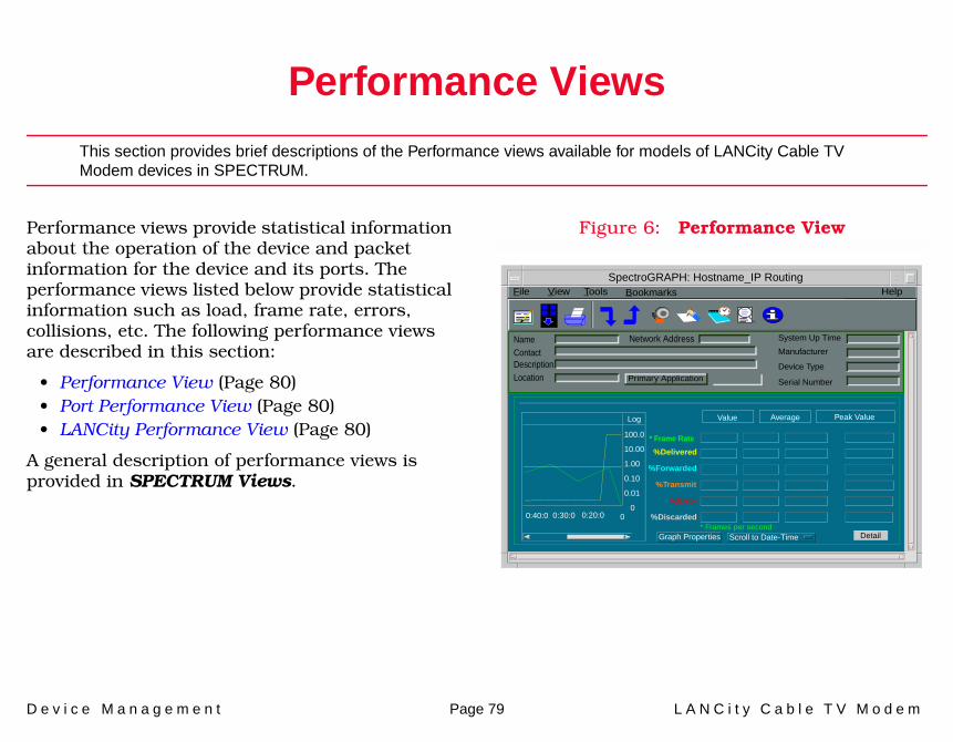
D e v i c e M a n a g e m e n t Page 79 L A N C i t y C a b l e T V M o d e m
Performance Views
This section provides brief descriptions of the Performance views available for models of LANCity Cable TV Modem devices in SPECTRUM.
Performance views provide statistical information about the operation of the device and packet information for the device and its ports. The performance views listed below provide statistical information such as load, frame rate, errors, collisions, etc. The following performance views are described in this section:
• Performance View (Page 80)• Port Performance View (Page 80)• LANCity Performance View (Page 80)
A general description of performance views is provided in SPECTRUM Views.
Figure 6: Performance View
Log
100.0
10.00
1.00
0.10
0.01
000:40:0 0:30:0 0:20:0
Value Average Peak Value
%Delivered
%Forwarded
%Transmit
%Error
%Discarded
DetailGraph Properties Scroll to Date-Time
SpectroGRAPH: Hostname_IP Routing
Primary Application
System Up Time
Manufacturer
Device Type
Serial Number
Network Address
* Frame Rate
NameContactDescriptionLocation
File View Help Tools
* Frames per second
Bookmarks
P e r f o r m a n c e V i e w s P e r f o r m a n c e V i e w
D e v i c e M a n a g e m e n t Page 80 L A N C i t y C a b l e T V M o d e m
Performance ViewAccess: From the Icon Subviews menu, select Performance for the Device icon.
This view provides performance information about the packets being passed through the device. The following packet statistics for the entire device are displayed in this view:
• * Frame Rate• % Delivered• % Forwarded• % Transmit• % Error• % Discarded
Port Performance ViewAccess: From the Icon Subviews menu for an Interface icon within the Device view or DevTop view, select Performance.
This view provides performance information about the packets being passed through a particular interface. The following packet statistics for the selected interface are displayed in this view:
• Load • Packet Rate
• % Error• % Discarded
LANCity Performance ViewAccess: From the Icon Subviews for the LCPV310App Application icon, select Performance.
This view displays the following statistics:
• CATV Data Packets Rx• CATV Data Packets Tx• Ethernet Data Packets Rx• Ethernet Data Packets Tx

D e v i c e M a n a g e m e n t Page 81 L A N C i t y C a b l e T V M o d e m
Configuration Views
The section describes the various Configuration views and subviews for the models of LANCity Cable TV Modem in SPECTRUM.
Configuration views allow you to view and modify current settings for the modeled device and its interfaces, ports, and applications. The following Configuration views are available for models of the LANCity Cable TV Modem:
• Device Configuration View• Interface Configuration View (Page 83)
Figure 7 shows the Device Configuration view for the LANCity modem.
Figure 7: Device Configuration View
lancity_LCPV310App of type LCPV310App of Landscape tulip: Primary
System Up Time
Manufacturer
Device Type
Serial Number
Network AddressModel NameContactDescriptionLocation
File View HelpTools
LANCity Configuration View
IP InformationIP Address
IP Address Mask
Remote Network Management IP Address
Remote Manager Gateway IP Address
Device InformationSoftware Version CPU Board Revision Level
Serial Number Prom Revision LevelBoard Part Number Manufacture Date
Unisic Revision Level Date Time
Upgrade ControlsSoftware Upgrade Load Server IP Address Start Down Load
Load Server Gateway IP Address Upgrade File
Load Protocol For Software Upgrade Reset Device
NVRAM Flash Write Down Load Status
Bookmarks
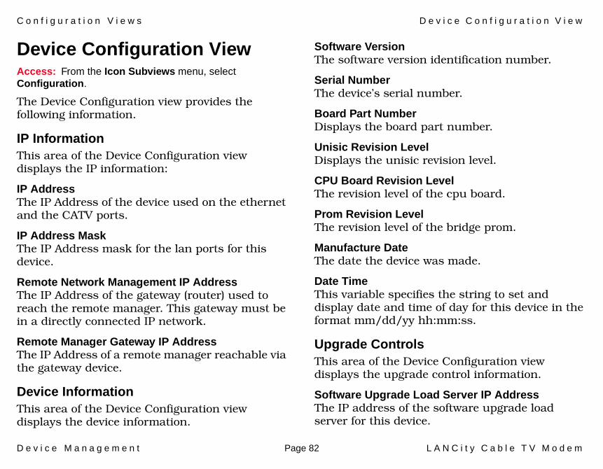
C o n f i g u r a t i o n V i e w s D e v i c e C o n f i g u r a t i o n V i e w
D e v i c e M a n a g e m e n t Page 82 L A N C i t y C a b l e T V M o d e m
Device Configuration ViewAccess: From the Icon Subviews menu, select Configuration.
The Device Configuration view provides the following information.
IP InformationThis area of the Device Configuration view displays the IP information:
IP AddressThe IP Address of the device used on the ethernet and the CATV ports.
IP Address MaskThe IP Address mask for the lan ports for this device.
Remote Network Management IP AddressThe IP Address of the gateway (router) used to reach the remote manager. This gateway must be in a directly connected IP network.
Remote Manager Gateway IP AddressThe IP Address of a remote manager reachable via the gateway device.
Device InformationThis area of the Device Configuration view displays the device information.
Software VersionThe software version identification number.
Serial NumberThe device’s serial number.
Board Part NumberDisplays the board part number.
Unisic Revision LevelDisplays the unisic revision level.
CPU Board Revision LevelThe revision level of the cpu board.
Prom Revision LevelThe revision level of the bridge prom.
Manufacture DateThe date the device was made.
Date TimeThis variable specifies the string to set and display date and time of day for this device in the format mm/dd/yy hh:mm:ss.
Upgrade ControlsThis area of the Device Configuration view displays the upgrade control information.
Software Upgrade Load Server IP AddressThe IP address of the software upgrade load server for this device.

C o n f i g u r a t i o n V i e w s I n t e r f a c e C o n f i g u r a t i o n V i e w
D e v i c e M a n a g e m e n t Page 83 L A N C i t y C a b l e T V M o d e m
Load Server Gateway IP AddressThe IP address of the gateway used to reach the software upgrade load server if the load server is not in the same network as this device. If the load server is in the same network, then no load server gateway need be specified.
Load Protocol For Software UpgradeThe protocol to be used for software upgrade.
NVRAM Flash WriteSet this control variable so that the parameters and field support history file are saved in flash NVRAM.
Start Down LoadInitiates a software upgrade by requesting the file “lcLcpLoadFile” from the IP address specified in “lcLcpLsIpAddress.”
Upgrade FileThe load file that is requested when software is initiated.
Reset DeviceSet this variable to reset the device. The parameters and field support history file are saved to flash NVRAM.
Down Load StatusIndicates the status of the previously initiated software upgrade.
Interface Configuration ViewAccess: From the Icon Subviews menu for a selected Interface icon in the Interface Device view, select Interface Configuration.
This view provides the following information for the selected interface.
Operation StatusThe current operational state of the interface (Up, Down, or Testing).
Admin. StatusThe desired operational state of the interface (Up, Down, or Testing).
Last ChangeThe System “UpTime” value when the interface entered its current operational state.
IP Address/Network MaskThis window provides a list of the user-defined names and IP addresses for the interface.
Physical AddressThe Ethernet (MAC) address of the interface.
BandwidthThe estimated bandwidth of the interface, measured in bits per second. For interfaces that do not vary in bandwidth, or no accurate estimate can be made, a nominal bandwidth is provided.
C o n f i g u r a t i o n V i e w s I n t e r f a c e C o n f i g u r a t i o n V i e w
D e v i c e M a n a g e m e n t Page 84 L A N C i t y C a b l e T V M o d e m
Packet SizeThe largest packet that can be transmitted or received by the port, displayed in octets.
Queue LengthThe length of the outbound packet queue, in packets.
Func AddrEnables the IEEE Spanning Tree Protocol at the TrBRF level to use the IBM bridge functional.
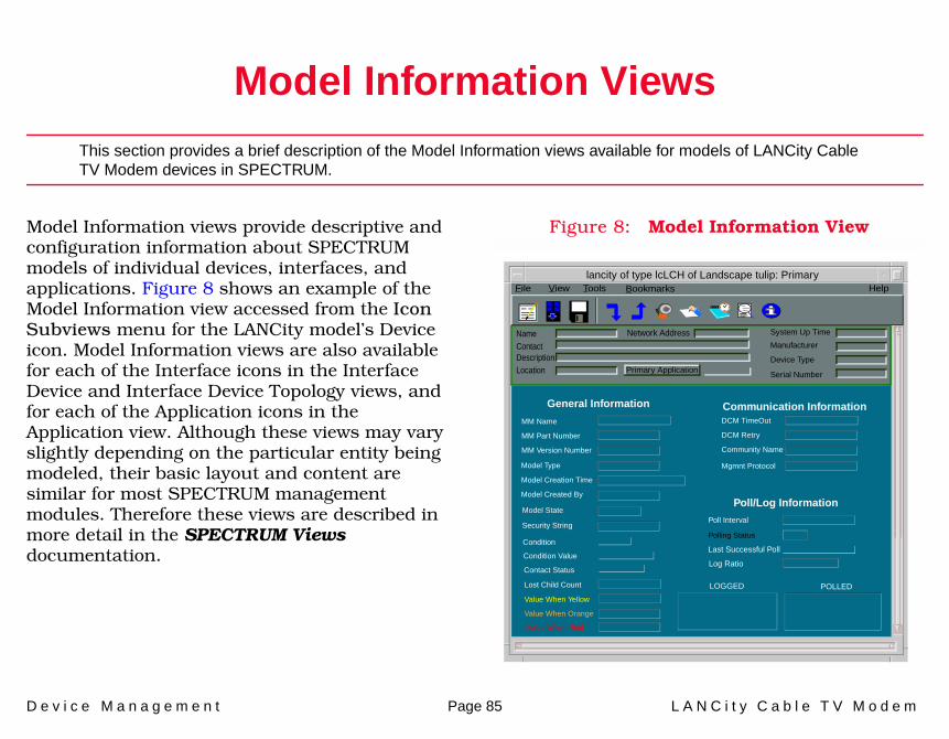
D e v i c e M a n a g e m e n t Page 85 L A N C i t y C a b l e T V M o d e m
Model Information Views
This section provides a brief description of the Model Information views available for models of LANCity Cable TV Modem devices in SPECTRUM.
Model Information views provide descriptive and configuration information about SPECTRUM models of individual devices, interfaces, and applications. Figure 8 shows an example of the Model Information view accessed from the Icon Subviews menu for the LANCity model’s Device icon. Model Information views are also available for each of the Interface icons in the Interface Device and Interface Device Topology views, and for each of the Application icons in the Application view. Although these views may vary slightly depending on the particular entity being modeled, their basic layout and content are similar for most SPECTRUM management modules. Therefore these views are described in more detail in the SPECTRUM Views documentation.
Figure 8: Model Information View
lancity of type lcLCH of Landscape tulip: Primary
Primary Application
System Up Time
Manufacturer
Device Type
Serial Number
Network AddressNameContactDescriptionLocation
File View Help Tools
MM Version Number
MM Name
MM Part Number
General Information
Model Created By
Model Type
Model Creation Time
Model State
Security String
Communication Information
Community Name
DCM TimeOut
DCM Retry
Poll/Log Information
Poll Interval
Polling Status
Mgmnt Protocol
Condition
Condition Value
Contact Status
Lost Child Count
Value When Yellow
Value When Orange
Value When Red
Last Successful Poll
Log Ratio
LOGGED POLLED
Bookmarks

D e v i c e M a n a g e m e n t Page 86 L A N C i t y C a b l e T V M o d e m
91
Index
AAborted Transmission Frames
Count 44Accessing SPECTRUM Views 8Achieved Block Sync 34Address
Interface IP 13Physical (MAC) 13
Address Translation Table 14Admin. Status 83Administrative Status Label 12Alignment 28Alignment Error Count 43Allocator Delay 61Application View
LCPV210 Application 18ASIC Buffer Address 61ASIC Buffer Index 61ASIC Filtered Type 23ASIC Filtered Type 1-8 23ASIC Frames Received 32ASIC Frames Transmitted 32ASIC Local LAN 23Asic Packets Received 21Asic Packets Transmitted 21Asic Rate Performance View 19
Packet Collisions 20
Packets Deferred 20Packets Detected CRC 20Packets Filtered 20Packets Received 20Packets Transmitted 20Received Bits Per Second 19Transmitted Bits Per Second 19
Assumed Frequency Delta from Channel 24
Auto Install Statistics View 30Average Block Sync Demodulator
Output 32Average Loop Delay Demodulator
Output 33
BBandwidth 83Bandwidth Missed 63Bidstate 68Block Sync Established 26Block Sync Lost 36Block Sync State 34, 60BRF Configuration View 84Bridge Resets 36, 53Broadcast Filter 46Broadcast Filtering 23
Broadcasts Received 29BS Demodulator Output Standard
Deviation 32Byte Count 28Byte Count Errors 43
CCATV Limit Rollover 68CATV Load Indicator 25CATV Network Load 25CATV Receive Frequency 50CATV Transmit Frequency 50Collisions Detected 30Collisions Received 64CRC 28CRC Error Count 43Current Dynamic Entries 24Current Frequency Scan State 24Current Rx Frequency 24Current Security Group 22Current Security Group Filtering
Type 22Current Static Entries 24Current Transmit Level 30

I n d e x I n d e x
D e v i c e M a n a g e m e n t Page 87 L A N C i t y C a b l e T V M o d e m
DData Packets Received 54Data Packets Transmitted 54, 55Default Transmit Level 31Default Transmit Power Level 32Deferred Transmitted Frames
Count 44Delta Levels 36Demodulator Output Std
Deviation 68Device Control View 20
Asic Packets Received 21Asic Packets Transmitted 21Ethernet Devices In Filtering
Database 20Ethernet Devices Supported By
Workgroup Bridge 20Maximum Receive Merit 21Maximum Transmit Merit 21Non-Pacer Hello 20Pacer Hello 20Receive Merit Limit 21Reset Device 21Snmp Access 20Sonic Packets Received 21Sonic Packets Transmitted 20Transmit Merit Limit 21Write to Flash 21
Down Load Status 21, 83Download View 21
Down Load Status 21
Gateway IP Address 21Load File 21Load Protocol 21Load Server IP Address 21Start Down Load 21
EECT Error Level 66Ending Rx Frequency 24Ethernet Devices In Filtering
Database 20Ethernet Devices Supported By
Workgroup Bridge 20Ethernet Down Count 37Ethernet Limit Rollover 68Ethernet Load Indicator 25Ethernet Network Load 25Ethernet Packets Per Error 25Ethernet Up Indicator 25Excess Collisions 28, 43Excess Deference 28Excess Pacer Attempts 37Excessive Pacer Attempts 35
FFIFO Overrun 70Filter Security Group View 22
Broadcast Filtering 23
Current Security Group 22Current Security Group Filtering
Type 22Multicast Filtering 23Packet Type 1-8 23Packet Type Filtering 22Security Group Filtering 22
Filter Table Control View 24Current Dynamic Entries 24Current Static Entries 24Max Dynamic Blocks Used 24Max Dynamic Entries Allowed 24Max Static Entries Allowed 24Max Trie Table Chains Depth 24
Frames Filtered 54Frames Forwarded 54Frames Received 30Frames Too Big 28Frames Transmitted 30Frequency Scan Override 26Frequency Scan View 24
Assumed Frequency Delta from Channel 24
Current Frequency Scan State 24Current Rx Frequency 24Ending Rx Frequency 24Number of Scans Made 24Scan Increment 24Starting Rx Frequency 24
I n d e x I n d e x
D e v i c e M a n a g e m e n t Page 88 L A N C i t y C a b l e T V M o d e m
GGateway IP Address 21Gauge Control Panel 13Group Filter 45
HHeadend Reference 27Health Summary View 25
Block Sync Established 26CATV Load Indicator 25CATV Network Load 25Ethernet Load Indicator 25Ethernet Network Load 25Ethernet Packets Per Error 25Ethernet Up Indicator 25MAC Packets Per Mac Error 25Max Delta Between Block Sync
And Loop Delay 26Min/Max Block Sync Levels Since
Block Sync 26Min/Max Block Sync Levels Since
Boot Up 26Min/Max Loop Delay Level
(dbs) 26Pacer Change Indicator 26Retain/Lost Block Sync 26Unilink Up Indicator 25
HRN Equalization Enabled 69
IIcons
Interface 12, 15Imagined Coefficient 28, 34Inaccessible Bus Count 43Interface
Type, Device 12Interface Address Translation
Table 14Interface Device Topology View 15Interface Icon
Administrative Status Label 12Interface Type Label 15
Interface icon 12Interface Type Label 15IP Address 82IP Address Mask 82IP Address/Network Mask 83
LLast Change 83Last Pacer 35lcLCB 8lcLCH 8lcLCP 8lcLCW 8LCN Parameters View 26LCPV210 Application 18
Asic Rate Performance View 19
Auto Install Statistics View 30Device Control View 20Download View 21Filter Security Group View 22Filter Table Control View 24Frequency Scan View 24Health Summary View 25LCN Parameters View 26Maintenance Summary View 35Miscellaneous Statistics View 31Modem Control View 32Performance Summary View 37Receive/Transmit Coefficient
Table View 27Software Filtered Frames View 23Sonic Error View 28Sonic Rate View 29Sonic Statistics View 29Support History Table 38Trap Destination View 39Trap Type View 39Unilink Protocol View 34
LD Demodulator Output Standard Deviation 33
Levels Calibrated 31Load File 21Load Protocol 21Load Server IP Address 21Loop Delay 30Loss Block Sync 53Lost Block Sync 34Lost Block Sync Count 59
I n d e x I n d e x
D e v i c e M a n a g e m e n t Page 89 L A N C i t y C a b l e T V M o d e m
Lost From Block Sync State 35
MMAC Errors 38MAC Packets Per Mac Error 25Maintenance Summary Reset 41Maintenance Summary View 35Match Count 55, 57, 58Match Reset Count 55, 57, 58Max Delta Between Block Sync And
Loop Delay 26Max Dynamic Blocks Used 24Max Dynamic Entries Allowed 24Max Static Entries Allowed 24Max Trie Table Chains Depth 24Maximum Concatenation 69Maximum Receive Merit 21Maximum Transmit Merit 21Min/Max Block Sync Levels Since
Block Sync 26Min/Max Block Sync Levels Since
Boot Up 26Min/Max Loop Delay Level (dbs) 26Miscellaneous Statistics View 31Missed Packets 28Modem Control View 32Multicast Filter 46Multicast Filtering 23Multicasts Received 29
Multiple-User Spanning Tree Cable Modem 7
NNetwork Access Priority 26, 50Network I/O ports 15Network Pacer 59Network Type 13Non Pacer Hello 65Non Unilink Received 63Non Unilink Transmitted 63Non-Pacer Hello 20Novell 45Number of Scans Made 24NVRAM Flash Write 83
OOperation Status 83
PPacer Address 35, 59Pacer Allowed 35, 59Pacer Change Indicator 26Pacer Changed 37Pacer Hello 20, 65Pacer State 78
Pacer Status 33, 35Packet Collisions 20Packet Size 84Packet Type 1-8 23Packet Type Filtering 22Packets Deferred 20Packets Detected CRC 20Packets Filtered 20Packets Filtered in a Different
Security Group 23Packets Processed/Received 37Packets Received 20Packets Transmitted 20Performance Summary Reset 41Performance Summary View 37Personal Cable Modem 7Physical Address 83Preferred Pacer 35, 59Provisioning Server 7Public Contention 61
QQueue Length 84
RReal Coefficient 28, 34Receive Channel Performance 41Receive Equalization Mean 68
I n d e x I n d e x
D e v i c e M a n a g e m e n t Page 90 L A N C i t y C a b l e T V M o d e m
Receive Equalization Merit 31Receive Equalization Std
Deviation 68Receive Errors 28Receive Frequency 27, 31, 41Receive Merit Limit 21Receive/Transmit Coefficient
Table 34Receive/Transmit Coefficient Table
View 27Received ASIC Packet Total 64Received Bits 29Received Bits Per Second 19Received Broadcast Frames
Count 44Received Frames Count 44Received Merit Limit 65Received Merit Maximum 65Received Multicast Frames
Count 44Received Packets 29Received SONIC Packet Total 65Reserved Bandwidth 50Reset ASIC Statistics 63Reset Count 56Reset Device 21, 83Reset Ethernet Statistics 44Reset Software Filtering
Statistics 23Reset Sonic Statistics 30Reset Statistics 35Reset Unilink Statistics 59
Retain/Lost Block Sync 26Revid Counter 63
SScan Increment 24Secondary Address Panel 14Security Group Filtering 22Serial Number 82Serial ports 15Snmp Access 20Software Filtered Frames View 23
ASIC Filtered Type 23ASIC Filtered Type 1-8 23ASIC Local LAN 23Packets Filtered in a Different
Security Group 23Reset Software Filtering
Statistics 23SONIC Filtered Type 23SONIC Filtered Type 1-8 23SONIC Local LAN 23
Sonic Buffer Address 71Sonic Error View 28Sonic Errors 30SONIC Filtered Type 23SONIC Filtered Type 1-8 23SONIC Frames Received 32SONIC Frames Transmitted 32SONIC Local LAN 23Sonic Packets Received 21
Sonic Packets Transmitted 20Sonic Rate 30Sonic Rate View 29Sonic Statistics View 29Start Down Load 21, 83Starting Rx Frequency 24Support History Table 38System Up Time 36, 53
TTotal Errors Count 54Total Transmit/Receive Errors 37Transmission Frequency 41Transmit Channel Performance 41Transmit Coefficient Table 28Transmit Equalization Count 68Transmit Equalization Merit 31Transmit Frequency 27, 31Transmit Merit Limit 21, 65Transmit Merit Maximum 65Transmit Power 74Transmitted ASIC Packet Total 64Transmitted Bits 29Transmitted Bits Per Second 19Transmitted Frames Collisions
Count 44Transmitted Frames Count 44Transmitted Packets 29Transmitted SONIC Packet Total 65Trap 66

I n d e x I n d e x
D e v i c e M a n a g e m e n t Page 91 L A N C i t y C a b l e T V M o d e m
Trap Destination Status 39Trap Destination View 39Trap Status 39Trap Type 39Trap Type View 39TXOP Saved 63
UUnilink Down Count 37Unilink Errors 54Unilink Protocol View 34Unilink Received 63Unilink Transmitted 63Unilink Up Indicator 25Upgrade File 83
VViews
Configuration 81Model Information 85
WWrite to Flash 21