Embed Size (px)
Citation preview
[189]
Agris on-line Papers in Economics and Informatics
Volume VII Number 4, 2015
Landmark Finding Algorithms for Indoor Autonomous Mobile Robot Localization L. Tóth, S. Paulovič, Z. Palková, L. Vacho
Department of Electrical Engineering, Automation and Informatics, Faculty of Engineering, Slovak University of Agriculture in Nitra Slovak Republic
AbstractThis contribution is oriented to ways of computer vision algorithms for mobile robot localization in internal and external agricultural environment. The main aim of this work was to design, create, verify and evaluate speed and functionality of computer vision localization algorithm. An input colour camera data and depth data were captured by MS® Kinect sensor that was mounted on 6-wheel-drive mobile robot chassis. The design of the localization algorithm was focused to the most significant blobs and points (landmarks) on the colour picture. Actual coordinates of autonomous mobile robot were calculated out from measured distances (depth sensor) and calculated angles (RGB camera) with respect to landmark points. Time measurement script was used to compare the speed of landmark finding algorithm for localization in case of one and more landmarks on picture. The main source code was written in MS Visual studio C# programming language with Microsoft.Kinect.1.7.dll on Windows based PC. Algorithms described in this article were created for a future development of an autonomous agronomical mobile robot localization and control.
Keywords: Computer vision, localization, MS® Kinect, algorithm, agronomical mobile robot.
Tóth, L., Paulovič, S., Palková Z. and Vacho, L. (2015) “Landmark Finding Algorithms for Indoor Autonomous Mobile Robot Localization”, AGRIS on-line Papers in Economics and Informatics, Vol. 7, No. 4, pp. 189 - 197, ISSN 1804-1930.
IntroductionIn this era there are many available solutions for indoor and outdoor navigation systems. Usually these navigation systems are based on odometria or global positioning system (GPS). Human obtain the most of information by vision. Designs of an autonomous mobile robots and inputs control algorithms are built by using conventional integrated sensors. Only a tiny sphere of research teams are working on a camera sensing and processing multidimensional scenes. Nowadays, satisfactory results are not achieved in the field of navigation yet; where the inputs for control algorithm are obtained from complex camera systems.
Duchoň (2012) says that localization represents a set of tasks that are guide to determinate object’s place or position in an environment. A localization system is a technology that estimates current location to run an autonomous navigation systems safely and consistently (Abdel Hafez et al., 2008; Son et al, 2015; Royer et al., 2007; Wang et al., 2006). Object’s position can be assigned relatively, with respects to another object’s position
in environment, or absolutely, with respects to beforehand defined coordinate system. The mobile robot is not able to make useful activity, without knowing about, where in environment it is. It seems, that the answer to the most important question: “Where am I?” doesn’t exist, and any universal solution doesn’t exist in robotics either. Especially, the reason is the measurement’s uncertainty of used sensors for the mobile robot localization. Therefore, mixed robot localizing methods are applied in the mobile robot applications, where each one of method has some pro-and-con. For this reason, application is very individual. Conventionally, sensor based vision localization systems have three inherent limitations: sensitivity to illumination variations, viewpoint variations, and high computational complexity (Son, J. et al., 2015).
Practically proved methods like triangulation, trilateration, modern methods like inertial navigation methods, but also difficult mathematic probability and statistical methods are used in sphere of mobile robot localization. Many authors (Son, J. et al., 2015; Kim, H. et al., 2015;
[190]
Landmark Finding Algorithms for Indoor Autonomous Mobile Robot Localization
Hu, G. et al., 2012; Davison, A. J. et al., 2007; Eade, E. et.al., 2006; Wolf, J. et.al., 2002; Ohya, A. et al., 1998) see big potential in computer vision as a very useful tool for autonomous robot localization system (SLAM).
Materials and methodsEnvironment property extraction based localization is a specific localization where an application needs sufficient precise sensors, e.g. laser range finders. Trilateration and trilateration localization methods belong to this group. The triangulation methods are applied for detected natural environment marks like edge of door or edge caused by colour difference. If these environment marks are detected exactly, then this information may be used as the input for triangulation method and it can help to determine the absolute position of the mobile robot. But the reactive movement is determined between two positions of the mobile robot more frequently (Duchoň, 2012).
Vision-based localization system, frequently called as vision odometry, is a relative localization method based on obtained information from visual system. The visual systems are usually mounted on mobile robots in mobile robotics sphere and sense three dimensional environments in one plain.
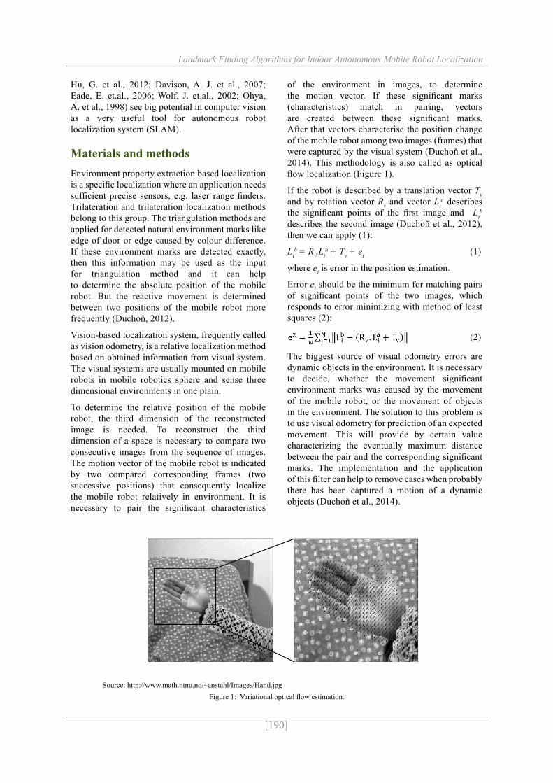
To determine the relative position of the mobile robot, the third dimension of the reconstructed image is needed. To reconstruct the third dimension of a space is necessary to compare two consecutive images from the sequence of images. The motion vector of the mobile robot is indicated by two compared corresponding frames (two successive positions) that consequently localize the mobile robot relatively in environment. It is necessary to pair the significant characteristics
of the environment in images, to determine the motion vector. If these significant marks (characteristics) match in pairing, vectors are created between these significant marks. After that vectors characterise the position change of the mobile robot among two images (frames) that were captured by the visual system (Duchoň et al., 2014). This methodology is also called as optical flow localization (Figure 1).
If the robot is described by a translation vector Tv and by rotation vector Rv and vector Li
a describes the significant points of the first image and Li
b describes the second image (Duchoň et al., 2012), then we can apply (1):
Lib = Rv.Li
a + Tv + ei (1)
where ei is error in the position estimation.
Error ei should be the minimum for matching pairs of significant points of the two images, which responds to error minimizing with method of least squares (2):
(2)
The biggest source of visual odometry errors are dynamic objects in the environment. It is necessary to decide, whether the movement significant environment marks was caused by the movement of the mobile robot, or the movement of objects in the environment. The solution to this problem is to use visual odometry for prediction of an expected movement. This will provide by certain value characterizing the eventually maximum distance between the pair and the corresponding significant marks. The implementation and the application of this filter can help to remove cases when probably there has been captured a motion of a dynamic objects (Duchoň et al., 2014).
Source: http://www.math.ntnu.no/~anstahl/Images/Hand.jpgFigure 1: Variational optical flow estimation.

[191]
Landmark Finding Algorithms for Indoor Autonomous Mobile Robot Localization
Multiple methods and procedures can be selected for a digital image processing and for purpose of obtaining some information that will be served to the mobile robot localization system. The environment has the biggest impact wherever the mobile robot will move. Under this condition, the image processing algorithms should be chosen carefully. In addition, a fast image processing is required with correct output information. The environment and objects in the environment are containing characteristic features that are possible to use as landmarks, e.g. edges, different colours or surface topography and shadows.
The Canny edge detector is useful at first step of the image processing. In principle, Canny edge detector is composed by several elements that are used at image analysis. These include, for example: noise suppression, application of a convolution operator with a mask, calculate the direction and the intensity of edges and others. Multiple steps combined can be considered as an advantage of this detector, although more time is required to perform operations. Minor drawback may be the sensitivity; unwanted edges can be obtained on the output image in addition to the necessary edges. This could be eliminated by threshold intensity. The Hough transformation is a standard method for shape recognition in digital images (Yuen, 1990). It was firstly applied to the recognition of straight lines and later extended to circles and ellipses (Duda, 1972). The Hough transformation has more advantages: robustness to noise, robustness to shape distortions and to occlusions or missing parts of an object. Its main disadvantage is the fact that computational and storage requirements of the algorithm are increased as the power of the dimensionality of the curve (Ioannou, 1999).
The above description is the summary of methods that can be changed and controlled by an appropriate control algorithm. One of the ways is using fuzzy control algorithm to decide, which method is relatively better for localization in the concrete situation. Hrubý (2007) says that fuzzy control is qualitative control based on qualitative description of real systems. We do not need to know the exact equation of control system. One of main benefits of fuzzy control system is intuitiveness of design, that allows control system designing too, where isn’t available a mathematical model of the system (environment) or it is hardly determinable (Hrubý et al., 2007).
Results and discussionThe both, the colour camera and the depth sensor of the MS® Kinect capture images in resolution 640x480pixels at 30fps. The colour and the depth sensor capture angle are not the same, the depth camera has smaller capture angle. Different vertical and horizontal capture angles of both sensors cause difference between captured images of the scene, so an image calibration process is needed. The colour image sequence captured by the colour camera was calibrated manually i.e. the original width and height of the colour images were reduced (deleted) in relation to image captured by the depth sensor. The image calibration is described next; a rectangle calibration object was moved in front of the depth camera, from one side of depth image to another side. When the calibration object on the depth image touched the border of the depth image, the colour image pixel lines are deleted from that side up to the border of calibration object appeared on the colour image. These steps are repeated on each side of the colour image. Then a new colour image was created with new width and height, so the size of the final colour image will be smaller.
After the calibration process, the algorithm calculated the ratios between depth image and new colour image width and height. Definition of ratios is needed, because the new colour image size was reduced and the depth image was not. The colour and the depth image do not need to have the same resolution, but they need to have the same aspect ratio. The calculation of the ratio for each dimension is shown next in formula (3) for width and for height formula (4):
(3)
(4)
where:
Rx – calibration ratio for width ( x line );Ry – calibration ratio for height ( y line );xorg , yorg – width and height of the depth image;xcalib , ycalib – width and height of the new calibrated colour image from VGA camera.These calibration ratios were used for determining the distance at pixel on the depth image.
Landmark finding algorithm should be able to find shining colour objects, edges, circles, lines or rectangles by using of RGB camera. For example tree stumps, wine grapes stems, poles, ground
[192]
Landmark Finding Algorithms for Indoor Autonomous Mobile Robot Localization
and grass colour contrast and even static shadows indoor and outdoor in agrarian sector. The main landmark finding algorithm should memorize constantly set vicinity of these objects on images. The landmark finding algorithm should these object notice on a new image anytime. Therefore, Khan et.al. (2012) image processing algorithm, upper mentioned Duchoň’s (2014) optical flow algorithm or colour comparing histogram based method could be applied. However MS® Kinect colour camera colour sensing and our algorithm are dependent from ambient illuminance (light) level, for monitoring this variable, our mobile robot NUC (fig. 11a) was supplemented by an external light-dependent resistor monitor. The value of measured ambient illuminance level compensatesthe RGB colour offset. The colour histogram (that was calculated by found landmark) can characterise the memorised landmarks. Individual colours classifying can be reached in accordance to the ambient light levels by fuzzy control system. The advantage of fuzzy control versus conventional methods is the ability to synchronous control of multiple independent physical variables (Cviklovič, 2011). Landmark finding algorithm can find landmarks like flat objects with depth sensor help too. Found landmarks are presented by one pixel i.e. by centre of rectangular frame drawn around colour blob of landmark.
Remembered landmarks searching algorithm speed will be the dominant factor at algorithm choice (fuzzy control). If the image processing speed decreases or the response time increases, captured image size (resolution) will be decreased on RGB camera device.
Information about the key point’s (landmark’s) distance is allocated at xfinal, yfinal co ordinates of the depth image pixel. The xfinal, yfinal co ordinates are necessary to calculate (5) and (6) for correct
pixel identification in the depth picture:
xfinal = Rx * xlandmark (5)
yfinal = Ry * ylandmark (6)
where:
xfinal, yfinal – corrected x and y co-ordinate of the landmark centre pixel on depth image;Rx , Ry – calibration ratio for width and height (x, y co-ordinate ratio);xland, yland – x and y co-ordinate of the recognized landmark centre;
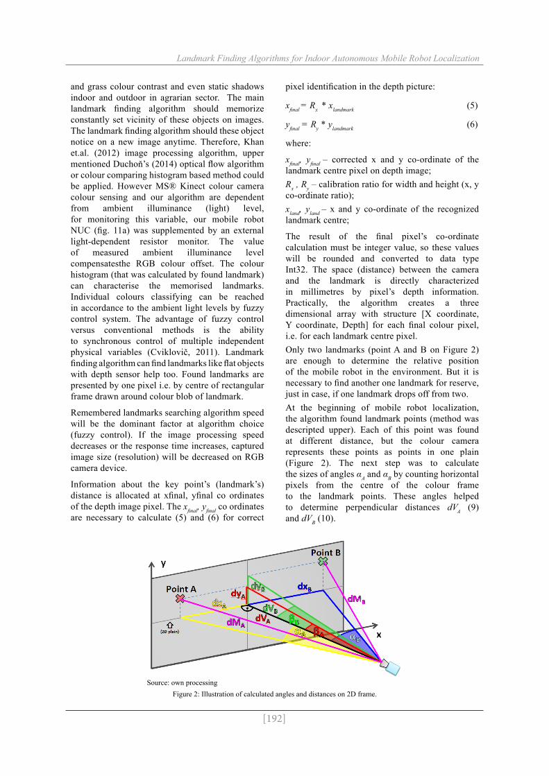
The result of the final pixel’s co-ordinate calculation must be integer value, so these values will be rounded and converted to data type Int32. The space (distance) between the camera and the landmark is directly characterized in millimetres by pixel’s depth information. Practically, the algorithm creates a three dimensional array with structure [X coordinate, Y coordinate, Depth] for each final colour pixel, i.e. for each landmark centre pixel. Only two landmarks (point A and B on Figure 2) are enough to determine the relative position of the mobile robot in the environment. But it is necessary to find another one landmark for reserve, just in case, if one landmark drops off from two.At the beginning of mobile robot localization, the algorithm found landmark points (method was descripted upper). Each of this point was found at different distance, but the colour camera represents these points as points in one plain (Figure 2). The next step was to calculate the sizes of angles αA and αB by counting horizontal pixels from the centre of the colour frame to the landmark points. These angles helped to determine perpendicular distances dVA (9) and dVB (10).
Source: own processingFigure 2: Illustration of calculated angles and distances on 2D frame.
[193]
Landmark Finding Algorithms for Indoor Autonomous Mobile Robot Localization
Next formulas (7) (8) helped to calculate perpendicular distance dxA between the A point and perpendicular distance dxB between the B point and the axis of the colour camera (figure 2). There was needed to measure not only angle, but also the distances dMA and dMB by MS® Kinect depth sensor.
dxA = dMA . sinαA (7)
dxB = dMB . sinαB (8)
Parameters dVA (9) and dVB (10) represented the perpendicular distances of each one landmark point from the colour camera sight.
dVB = dMB . cosαB (9)
dVA = dMA . cosαA (10)
Furthermore, if some application needs the elevation of landmark points in the environment, parameters dyA (11) and dyB (12) characterise these values.
dyA = dVA . tgβA (11)
dyB = dVB . tgβB (12)
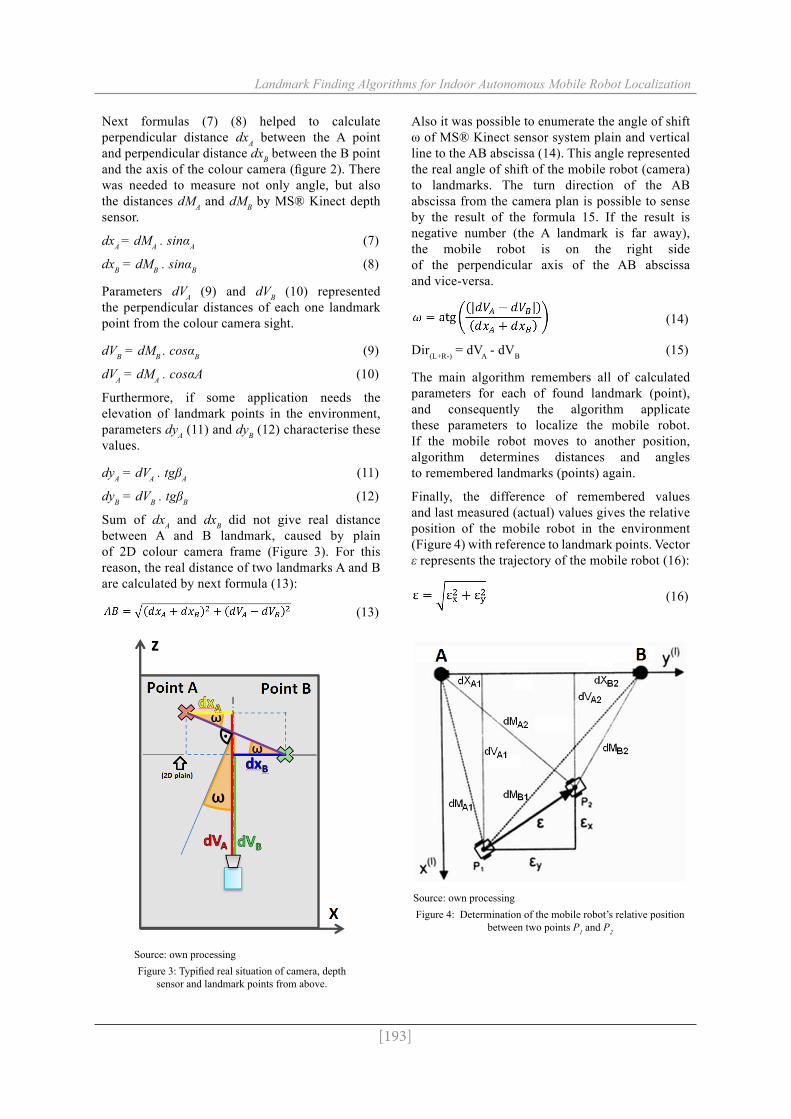
Sum of dxA and dxB did not give real distance between A and B landmark, caused by plain of 2D colour camera frame (Figure 3). For this reason, the real distance of two landmarks A and B are calculated by next formula (13):
(13)
Source: own processingFigure 3: Typified real situation of camera, depth
sensor and landmark points from above.
Also it was possible to enumerate the angle of shift ω of MS® Kinect sensor system plain and vertical line to the AB abscissa (14). This angle represented the real angle of shift of the mobile robot (camera) to landmarks. The turn direction of the AB abscissa from the camera plan is possible to sense by the result of the formula 15. If the result is negative number (the A landmark is far away), the mobile robot is on the right side of the perpendicular axis of the AB abscissa and vice-versa.
(14)
Dir(L+R-) = dVA - dVB (15)
The main algorithm remembers all of calculated parameters for each of found landmark (point), and consequently the algorithm applicate these parameters to localize the mobile robot. If the mobile robot moves to another position, algorithm determines distances and angles to remembered landmarks (points) again.
Finally, the difference of remembered values and last measured (actual) values gives the relative position of the mobile robot in the environment (Figure 4) with reference to landmark points. Vector ε represents the trajectory of the mobile robot (16):
(16)
Source: own processingFigure 4: Determination of the mobile robot’s relative position
between two points P1 and P2

[194]
Landmark Finding Algorithms for Indoor Autonomous Mobile Robot Localization
Results of the landmark finding algorithm for indoor localization are showed in stages: MS® Kinect colour camera output (Figure 5), landmark finding algorithm output (Figure 6), calibration
algorithm output (Figure 7), depth sensor output (Figure 8), depth measurement correction - error filtration algorithm output (Figure 9) and landmark points-angles finding algorithm output (Figure 10).
Source: own processingFigure 5: Output from MS® Kinect RGB camera (original
frame).
Source: own processingFigure 6: Landmark finding algorithm (from RGB camera
frame)
Source: own processingFigure 7: Result of RGB camera and depth sensor calibration
algorithm and landmarks.
Source: own processingFigure 8: Output from MS® Kinect Depth sensor (original
frame).
Source: own processingFigure 9: Depth measurement correction - error filtration
algorithm (corrected frame).
Source: own processingFigure 10: Landmark point angles finding algorithm (join
of RGB calibrated frame, found landmarks data, and corrected depth frame information).
[195]
Landmark Finding Algorithms for Indoor Autonomous Mobile Robot Localization
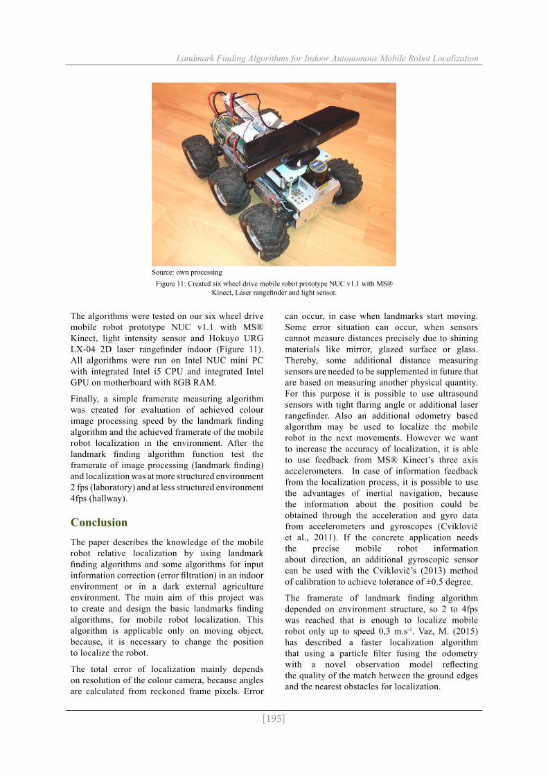
The algorithms were tested on our six wheel drive mobile robot prototype NUC v1.1 with MS® Kinect, light intensity sensor and Hokuyo URG LX-04 2D laser rangefinder indoor (Figure 11). All algorithms were run on Intel NUC mini PC with integrated Intel i5 CPU and integrated Intel GPU on motherboard with 8GB RAM.
Finally, a simple framerate measuring algorithm was created for evaluation of achieved colour image processing speed by the landmark finding algorithm and the achieved framerate of the mobile robot localization in the environment. After the landmark finding algorithm function test the framerate of image processing (landmark finding) and localization was at more structured environment 2 fps (laboratory) and at less structured environment 4fps (hallway).
ConclusionThe paper describes the knowledge of the mobile robot relative localization by using landmark finding algorithms and some algorithms for input information correction (error filtration) in an indoor environment or in a dark external agriculture environment. The main aim of this project was to create and design the basic landmarks finding algorithms, for mobile robot localization. This algorithm is applicable only on moving object, because, it is necessary to change the position to localize the robot.
The total error of localization mainly depends on resolution of the colour camera, because angles are calculated from reckoned frame pixels. Error
can occur, in case when landmarks start moving. Some error situation can occur, when sensors cannot measure distances precisely due to shining materials like mirror, glazed surface or glass. Thereby, some additional distance measuring sensors are needed to be supplemented in future that are based on measuring another physical quantity. For this purpose it is possible to use ultrasound sensors with tight flaring angle or additional laser rangefinder. Also an additional odometry based algorithm may be used to localize the mobile robot in the next movements. However we want to increase the accuracy of localization, it is able to use feedback from MS® Kinect’s three axis accelerometers. In case of information feedback from the localization process, it is possible to use the advantages of inertial navigation, because the information about the position could be obtained through the acceleration and gyro data from accelerometers and gyroscopes (Cviklovič et al., 2011). If the concrete application needs the precise mobile robot information about direction, an additional gyroscopic sensor can be used with the Cviklovič’s (2013) method of calibration to achieve tolerance of ±0.5 degree.
The framerate of landmark finding algorithm depended on environment structure, so 2 to 4fps was reached that is enough to localize mobile robot only up to speed 0,3 m.s-1. Vaz, M. (2015) has described a faster localization algorithm that using a particle filter fusing the odometry with a novel observation model reflecting the quality of the match between the ground edges and the nearest obstacles for localization.
Source: own processingFigure 11: Created six wheel drive mobile robot prototype NUC v1.1 with MS®
Kinect, Laser rangefinder and light sensor.
[196]
Landmark Finding Algorithms for Indoor Autonomous Mobile Robot Localization
These algorithms are primarily created for actual indoor autonomous mobile robot NUC and for future development of an autonomous agronomical mobile robot control in the agrarian sector. In regard of an external agricultural environment, sunlight is the limiting factor for depth camera sensor. The depth camera sensor works on constantly defined wavelength laser beams projected to the environment. The sunlight interference with these beams and thereby depth sensor cannot acquire the distances. The solution is the usage of the MS® Kinect at night with its enabled colour camera night vision function. Especially, application of this landmark finding algorithm for localization is suitable for small agricultural devices that are moving in agrarian sector between i.e. maize rows, vine yards or cornfield only at night. These localization algorithms are ideal for lawn movers too that are mowing the grass in the home gardens at cloudy weather.
One of the most suitable tasks for this landmark finding algorithm is spraying with the airblast sprayer between fruit trees or wine grapes. In this case, the main benefit of this algorithm is increasing the health and safety at workspace, because workers do not need to drive the sprayer tractor and meanwhile breathe the pesticides. The whole sprayer system could work autonomously with appropriate electro-mechanical actuating devices installed on agricultural machine.
Advantages of landmark finding algorithm for localization could be used in conjunction with precise fertilization research works too, where every single plant obtains only necessary amount of soil conditioner in dependence on plant nutrient index. Every coordinate of fertilized plants or places in row could be remembered and used to build a precise agrarian nutrient map.
Corresponding author:Ing. Ladislav TóthDepartment of Electrical Engineering, Automation and Informatics, Faculty of Engineering Slovak University of Agriculture in Nitra, TR. A. Hlinku 2, 949 76 Nitra, Slovak Republic Phone: +421 37 641 4763, E-mail: [email protected]
References[1] Abdel-Hafez, M. F., Kim, D. J., Lee, E., Chun, S., Lee, Y. J., Kang, T., Sung, S. Performance
improvement of the wald test for GPS RTK with the assistance of INS. International Journal of Control, Automation and Systems. 2008, Vol. 6, No. 4, p. 534-543. ISSN 1598-6446.
[2] Cviklovič, V. Alternative ways of navigation of autonomous mobile robots in agriculture. SUA in Nitra. 2011. Dissertation work.
[3] Cviklovič, V., Hrubý, D., Olejár, M., Lukáč, O. Comparison of numerical integration methods in strapdown inertial navigation algorithm. In Research in Agricultural Engineering. 2011, Vol. 57, special iss., p. 30-34. ISSN 1212-9151.
[4] Cviklovič, V., Hrubý, D., Olejár, M., Priatková, L. Gyroscope calibration with the method of simulated identification. Research in Agricultural Engineering. 2013, Vol. 59, spec iss., p. 22-26. ISSN 1212-9151.
[5] Davison, A. J., Reid, I. D., Molton, N. D., Stasse, O. MonoSLAM: Real-time single camera SLAM. IEEE Transactions on Pattern Analysis and Machine Intelligence. 2007, Vol. 29, No. 6, p. 1052-1067 ISSN 0162-8828.
[6] Duchoň, F., Králik, M., Babinec, A., Hubinský, P. Simple image processing algorithms for robot navigation in unknown environment. In Applied Mechanics and Materials. 2014, Vol. 613, p. 66-75. ISSN 1660-9336.
[7] Duchoň, F. Lokalizácia a navigácia mobilných robotov do vnútorného prostredia. 1st ed., Bratislava: Slovenská technická univerzita v Bratislava nakladateľstvo STU. 2012, p. 162. ISBN 978-80-227-3646-6.
[8] Duda, R. O., Hart, P. E. Use of the Hough transformation to detect lines and curves in pictures. Comm. Assoc. Comput. Mach. 1972, Vol. 15, p. 11-15.
[197]
Landmark Finding Algorithms for Indoor Autonomous Mobile Robot Localization
[9] Eade, E., Drummond, T. Scalable monocular SLAM. Proceedings of the IEEE Computer Society Conference on Computer Vision and Pattern Recognition. 2006, Vol. 1, art. No. 1640794, p. 469-476. ISSN 1063-6919.
[10] Hrubý, D., Amrich, M. Automatic fuzzy logic control of vehicle motion. In Acta technologica agriculturae. 2007, Vol. 10, No. 1, p. 14-17. ISSN 1335-2555.
[11] Hu, G., Huang, S., Zhao, L., Alempijevic, A., Dissanayake, G. A robust RGB-D SLAM algorithm. Proceedings of the IEEE International Conference on Intelligent Robots and Systems. 2012, art. No. 6386103, p. 1714-1719. ISSN 2153-0858.
[12] Ioannou, D., Huda, W., Laine, A. F. Circle recognition through a 2D Hough transform and radius histogramming. In Image Vision Comput. 1999, Vol. 17, p. 15–26. ISSN 0262-8856.
[13] Khan, F. S., Anwer, R. M., Weijer, J., Bagdanov, A. D., Vanrell, M., Lopez, A. M. Color attributes for object detection. Proceedings of the IEEE Conference Computer Vision and Pattern Recognition (CVPR). 2012, art. No. 6248068, p. 3306-3313. ISSN 1063-6919.
[14] Kim, H., Lee, D., Oh, T., Choi, H.-T., Myung, H. A probabilistic feature map-based localization system using a monocular camera. Sensors (Switzerland). 2015, Vol. 15, No. 9, p. 21636-21659. ISSN 1424-8220.
[15] Ohya, A., Kosaka, A., Kak, A. Vision-based navigation by a mobile robot with obstacle avoidance using single-camera vision and ultrasonic sensing. Proceedings of the IEEE Transactions on Robotics and Automation. 1998, Vol. 14, No. 6, p. 969-978, ISSN 1042 296X.
[16] Royer, E., Lhuillier, M., Dhome, M., Lavest, J.-M. Monocular vision for mobile robot localization and autonomous navigation. In International Journal of Computer Vision. 2007, Vol. 74, No. 3, p. 237-260. ISSN 0920-5691.
[17] Son, J., Kim, S., Sohn, K. A multi-vision sensor-based fast localization system with image matching for challenging outdoor environments. In Expert Systems with Applications. 2015, Vol. 42, No. 22, p. 8830-8839. ISSN 0957-4174.
[18] Vaz, M., Ventura, R. Real-time ground-plane based mobile localization using Depth Camera in Real Scenarios. In Journal of Intelligent and Robotic Systems: Theory and Applications. 2015, p. 12. ISSN 0921-0296.
[19] Wang, J., Zha, H., Copolla, R. Coarse-to-Fine vision-based localization by indexing scale-invariant features. Proceedings of the IEEE Transactions on Systems, Man and Cybernetics Part B: Cybernetics. 2006, Vol. 36, No. 2, p. 413-422. ISSN 1083-4419.
[20] Wolf, J., Burgard, W., Burkhardt, H. Robust vision-based localization for mobile robots using an image retrieval system based on invariant features. Proceedings of the IEEE International Conference on Robotics and Automation ICRA '02. 2002, Vol.1, p. 359-365. ISSN 1050-4729.
[21] Yuen, H., Princen, J., Illingworht, J., Kittler, J. Comparative study of Hough Transform methods for circle finding. Image and Vision Computing. 1990, Vol. 8, No. 1, p. 71-77. ISSN 0262-8856.