Embed Size (px)
Citation preview
STOP
A
3
LE
LAWN SOLID SOD
BERMUDAGRASS, TYP.
18" HARDWOOD MULCH
STEP OUT, TYP.
2
LO
1
LE
1
LE
1
LO
48
DWM
15
LOR
12
MIS
14
DFG
15
DDW
1
RB
175
LIR
12
AB
14
RR15
MO3
AG
60
LIR
3
LOR
5
AB
5
DDW
5
RR
20
SC
1
AG
5
DDW
25
MFG
5
DFG
5
AB
8
LOR
6
MIS
390
LIR
LAWN SOLID SOD
BERMUDAGRASS, TYP.
18" HARDWOOD MULCH
STEP OUT, TYP.
6
MO
LAWN SOLID SOD
BERMUDAGRASS, TYP.
5
AB
3
LOR
10
MFG
SHEET TITLE:
SHEET NUMBER:
PROJECT NUMBER:
GOC21007
DESCRIPTION
DESCRIPTIONDATE
DATE
CORPORATE:
GFC LEASING CORPORATION, LLC1131 ROCKINGHAM DRIVE, SUITE 250RICHARDSON, TX 75080
6201
CAM
PUS
CIRC
LE D
RIVE
EIR
VING
, TEX
AS 7
5063
TEL:
972
.870
.128
8W
WW
.IDST
UDIO
4.CO
MCL
IEN
T:
GOLD
EN C
HICK
- 18
24 SH
-6 S.
ALVI
N,
TX 7
7511
GFC
LEA
SIN
G C
ORP
ORA
TIO
N,
LLC
1131
RO
CKIN
GH
AM
DRI
VERI
CHA
RDSO
N,
TX 7
5080
ISSUE FOR PERMIT09/29/2021
10.06.21
STAT E OF T EXAS
TCET
HIRCAEPACSDNALDEE
GEIS
R
RT
422 6
KO
RI N HAUG
A N
LANDSCAPE NOTES
1. CONTRACTOR SHALL VERIFY ALL EXISTING AND
PROPOSED SITE ELEMENTS AND NOTIFY LANDSCAPE
ARCHITECT OF ANY DISCREPANCIES. SURVEY DATA
OF EXISTING CONDITIONS WAS SUPPLIED BY OTHERS.
2. CONTRACTOR SHALL LOCATE ALL EXISTING
UNDERGROUND UTILITIES AND NOTIFY LANDSCAPE
ARCHITECT OF ANY CONFLICTS. CONTRACTOR SHALL
EXERCISE CAUTION WHEN WORKING IN THE VICINITY
OF UNDERGROUND UTILITIES.
3. CONTRACTOR SHALL PROVIDE A MINIMUM 2% SLOPE
AWAY FROM ALL STRUCTURES.
4. CONTRACTOR SHALL FINE GRADE AREAS TO ACHIEVE
FINAL CONTOURS AS INDICATED. LEAVE AREAS TO
RECEIVE TOPSOIL 3" BELOW FINAL FINISHED GRADE IN
PLANTING AREAS AND 1" BELOW FINAL FINISHED
GRADE IN LAWN AREAS.
5. ALL PLANTING BEDS AND LAWN AREAS SHALL BE
SEPARATED BY STEEL EDGING. NO STEEL EDGING
SHALL BE INSTALLED ADJACENT TO BUILDINGS,
WALKS, OR CURBS. CUT STEEL EDGING AT 45 DEGREE
ANGLE WHERE IT INTERSECTS WALKS AND CURBS.
6. TOP OF MULCH SHALL BE 1/2" MINIMUM BELOW THE
TOP OF WALKS AND CURBS.
7. ALL LAWN AREAS SHALL BE SOLID SOD
BERMUDAGRASS, UNLESS OTHERWISE NOTED ON THE
DRAWINGS.
8. ALL REQUIRED LANDSCAPE AREAS SHALL BE
PROVIDED WITH AN AUTOMATIC UNDERGROUND
IRRIGATION SYSTEM WITH RAIN AND FREEZE SENSORS
AND EVAPOTRANSPIRATION (ET) WEATHER-BASED
CONTROLLERS AND SAID IRRIGATION SYSTEM SHALL
BE DESIGNED BY A QUALIFIED PROFESSIONAL AND
INSTALLED BY A LICENSED IRRIGATOR.
9. CONTRACTOR SHALL PROVIDE BID PROPOSAL LISTING
UNIT PRICES FOR ALL MATERIAL PROVIDED.
10. CONTRACTOR SHALL BE RESPONSIBLE FOR OBTAINING
ALL REQUIRED LANDSCAPE AND IRRIGATION PERMITS.
MAINTENANCE NOTES
1. THE OWNER, TENANT AND THEIR AGENT, IF ANY,
SHALL BE JOINTLY AND SEVERALLY RESPONSIBLE FOR
THE MAINTENANCE OF ALL LANDSCAPE.
2. ALL LANDSCAPE SHALL BE MAINTAINED IN A NEAT
AND ORDERLY MANNER AT ALL TIMES. THIS SHALL
INCLUDE MOWING, EDGING, PRUNING, FERTILIZING,
WATERING, WEEDING AND OTHER SUCH ACTIVITIES
COMMON TO LANDSCAPE MAINTENANCE.
3. ALL LANDSCAPE AREAS SHALL BE KEPT FREE OF
TRASH, LITTER, WEEDS AND OTHER SUCH MATERIAL
OR PLANTS NOT PART OF THIS PLAN.
4. ALL PLANT MATERIAL SHALL BE MAINTAINED IN A
HEALTHY AND GROWING CONDITION AS IS
APPROPRIATE FOR THE SEASON OF THE YEAR.
5. ALL PLANT MATERIAL WHICH DIES SHALL BE
REPLACED WITH PLANT MATERIAL OF EQUAL OR
BETTER VALUE.
6. CONTRACTOR SHALL PROVIDE SEPARATE BID
PROPOSAL FOR ONE YEAR'S MAINTENANCE TO BEGIN
AFTER FINAL ACCEPTANCE.
GENERAL LAWN NOTES
1. CONTRACTOR SHALL COORDINATE OPERATIONS AND
AVAILABILITY OF EXISTING TOPSOIL WITH ON-SITE
CONSTRUCTION MANAGER.
2. CONTRACTOR SHALL LEAVE LAWN AREAS 1" BELOW
FINAL FINISHED GRADE PRIOR TO TOPSOIL
INSTALLATION.
3. CONTRACTOR SHALL FINE GRADE AREAS TO ACHIEVE
FINAL CONTOURS AS INDICATED ON CIVIL PLANS.
ADJUST CONTOURS TO ACHIEVE POSITIVE DRAINAGE
AWAY FROM BUILDINGS. PROVIDE UNIFORM
ROUNDING AT TOP AND BOTTOM OF SLOPES AND
OTHER BREAKS IN GRADE. CORRECT IRREGULARITIES
AND AREAS WHERE WATER MAY STAND.
4. ALL LAWN AREAS SHALL BE FINE GRADED, IRRIGATION
TRENCHES COMPLETELY SETTLED AND FINISH GRADE
APPROVED BY THE OWNER'S CONSTRUCTION
MANAGER OR LANDSCAPE ARCHITECT PRIOR TO LAWN
INSTALLATION.
5. CONTRACTOR SHALL REMOVE ALL ROCKS 3/4"
DIAMETER AND LARGER, DIRT CLODS, STICKS,
CONCRETE SPOILS, ETC. PRIOR TO PLACING TOPSOIL
AND LAWN INSTALLATION.
6. CONTRACTOR SHALL MAINTAIN ALL LAWN AREAS
UNTIL FINAL ACCEPTANCE. THIS SHALL INCLUDE, BUT
NOT BE LIMITED TO: MOWING, WATERING, WEEDING,
CULTIVATING, CLEANING AND REPLACING DEAD OR
BARE AREAS TO KEEP PLANTS IN A VIGOROUS,
HEALTHY CONDITION.
7. CONTRACTOR SHALL GUARANTEE ESTABLISHMENT OF
ACCEPTABLE TURF AREA AND SHALL PROVIDE
REPLACEMENT FROM LOCAL SUPPLY IF NECESSARY.
SOLID SOD NOTES
1. PLANT SOD BY HAND TO COVER INDICATED AREAS
COMPLETELY. ENSURE EDGES OF SOD ARE TOUCHING.
TOP DRESS JOINTS BY HAND WITH TOPSOIL TO FILL
VOIDS.
2. ROLL GRASS AREAS TO ACHIEVE A SMOOTH, EVEN
SURFACE, FREE FROM UNNATURAL UNDULATIONS.
3. WATER SOD THOROUGHLY AS SOD OPERATION
PROGRESSES.
4. IF INSTALLATION OCCURS BETWEEN SEPTEMBER 1
AND MARCH 1, OVER-SEED BERMUDAGRASS SOD
WITH WINTER RYEGRASS, AT A RATE OF FOUR (4)
POUNDS PER ONE THOUSAND (1000) SQUARE FEET.
N 0 10 20 40
SCALE: 1" = 20'-0"
LANDSCAPE TABULATIONSTHE CITY OF ALVIN, TEXAS
STREETSCAPE STANDARDS
1. One (1) canopy is required for each fifty (50) feet of lot
width or portion thereof. Trees may be clustered or
spaced linearly.
STATE HIGHWAY 6: 161 l.f.
Required Provided
(3) trees, 3" cal. (3) trees, 3" cal.
PARKING LOT
1. For each fifteen (15) parking spaces, or fraction thereof, a
landscape island containing at least one hundred sixty-two
(162) square feet must be provided within the parking lot.
2. At least two (2) trees must be provided for each one
hundred sixty-two (162) square feet of required island.
3. All islands shall be completely landscaped with
groundcover.
Parking: 28 spaces
Required Provided
324 s.f. landscape area 353 s.f. landscape area
(2) islands (2) islands
(4) trees, 3" cal. (5) trees, 3" cal.
Drawing
LANDSCAPEPLAN
L1.01
SHEET TITLE:
SHEET NUMBER:
PROJECT NUMBER:
GOC21007
DESCRIPTION
DESCRIPTIONDATE
DATE
CORPORATE:
GFC LEASING CORPORATION, LLC1131 ROCKINGHAM DRIVE, SUITE 250RICHARDSON, TX 75080
6201
CAM
PUS
CIRC
LE D
RIVE
EIR
VING
, TEX
AS 7
5063
TEL:
972
.870
.128
8W
WW
.IDST
UDIO
4.CO
MCL
IEN
T:
GOLD
EN C
HICK
- 18
24 SH
-6 S.
ALVI
N,
TX 7
7511
GFC
LEA
SIN
G C
ORP
ORA
TIO
N,
LLC
1131
RO
CKIN
GH
AM
DRI
VERI
CHA
RDSO
N,
TX 7
5080
ISSUE FOR PERMIT09/29/2021
10.06.21
STAT E OF T EXAS
TCET
HIRCAEPACSDNALDEE
GEIS
R
RT
422 6
KO
RI N HAUG
A N
Drawing
LANDSCAPESPECIFICATIONS
AND DETAILS
L1.02
PREPARED SOIL MIX PER
SPECIFICATIONS; TILL 6" MINIMUM
OF PREPARED SOIL MIX INTO
6" DEPTH OF EXISTING SOIL
3/16" X 4" BLACK EDGING,
STAKES ON INSIDE; EDGING SHALL
BE 1/2" MAXIMUM HEIGHT
ABOVE FINISH GRADE
TOP OF MULCH 1/2"
MINIMUM BELOW TOP OF
CONCRETE WALK / CURB
CONCRETE WALK LAWN / FINISH GRADE
NOTE:
NO STEEL EDGING SHALL
BE INSTALLED ALONG
SIDEWALKS OR CURBS
ROOTBALL,
DO NOT DISTURB
NATIVE SOIL
POCKET PLANTING
NOT ALLOWED
SHRUBS / GROUNDCOVER;
REFER TO LANDSCAPE PLAN
TOPDRESS MULCH PER
SPECIFICATIONS; 2" MINIMUM
SETTLED THICKNESS
SCARIFY SIDES
REFER TO LANDSCAPE PLAN
FOR SPACING6"
A.
E.
C. B.
I.
H.
F.
G.
D.
TREE PLANTING DETAIL LEGEND
AND NOTES
A. TREE: TREES SHALL CONFORM WITH
LATEST AMERICAN STANDARD FOR
NURSERY STOCK. www.anla.org
B. TREE PIT: WIDTH TO BE AT LEAST TWO
(2) TIMES THE DIAMETER OF THE ROOT
BALL CENTER TREE IN HOLE & REST
ROOT BALL ON UNDISTURBED NATIVE
SOIL.
C. ROOT BALL: REMOVE TOP 13 BURLAP
AND ANY OTHER FOREIGN OBJECT;
CONTAINER GROWN STOCK TO BE
INSPECTED FOR GIRDLING ROOTS.
D. ROOT FLARE: ENSURE THAT ROOT
FLARE IS EXPOSED, FREE FROM MULCH,
AND AT LEAST TWO INCHES ABOVE
GRADE. TREES SHALL BE REJECTED
WHEN GIRDLING ROOTS ARE PRESENT &
ROOT FLARE IS NOT APPARENT.
E. ROOTBALL ANCHOR RING: REFER TO
MANUFACTURER'S GUIDELINES FOR
SIZING. PLACE ROOTBALL ANCHOR
RING ON BASE OF ROOTBALL, TRUNK
SHOULD BE IN THE CENTER OF THE
RING.
F. ROOT ANCHOR BY TREE STAKE
SOLUTIONS.
G. NAIL STAKE: REFER TO
MANUFACTURER'S GUIDELINES FOR
SIZING. INSTALL NAIL STAKES WITH
HAMMER OR MALLET FIRMLY INTO
UNDISTURBED GROUND. DRIVE NAILSTAKES FLUSH WITH "U" BRACKETADJACENT TO ROOTBALL (DO NOTDISTURB ROOTBALL).
H. BACKFILL: USE EXISTING NATIVE SOIL
(no amendments) WATER THOROUGHLY
TO ELIMINATE AIR POCKETS.
I. MULCH: DOUBLE SHREDDED
HARDWOOD MULCH 2 INCH SETTLED
THICKNESS, WITH 2" HT. WATERING
RING; ENSURE THAT ROOT FLARE IS
EXPOSED. BELOW GROUND STAKE
SHOULD NOT BE VISIBLE.
J. TREE STAKES:
TREE STAKE SOLUTIONS 'SAFETY
STAKE' BELOW GROUND MODEL
AVAILABLE FROM:
Tree Stake Solutions
ATTN: Jeff Tuley
(903) 676-6143
www.treestakesolutions.com
OR APPROVED EQUAL. TREES SHALL BE
STAKED BELOW GROUND WHERE
NECESSARY; ABOVE GROUND STAKING
IS EXPRESSLY PROHIBITED.
K. IT SHALL BE THE RESPONSIBILITY OF
THE CONTRACTOR TO OBTAIN A COPY
OF THE MANUFACTURER'S
SPECIFICATIONS PRIOR TO
INSTALLATION OF TREE STAKES.
CONTRACTOR SHALL ADHERE TO
MANUFACTURER'S INSTALLATION
GUIDELINES, SPECIFICATIONS, AND
OTHER REQUIREMENTS FOR TREE STAKE
INSTALLATION.
01TREE PLANTING DETAILNOT TO SCALE 02
SHRUB / GROUNDCOVER DETAILNOT TO SCALE
SECTION 32 9300 - LANDSCAPE
PART 1 - GENERAL
1.1 REFERENCED DOCUMENTS
A. Refer to Landscape Plans, notes, details, bidding requirements,
special provisions, and schedules for additional requirements.
1.2 DESCRIPTION OF WORK
A. Work included: Furnish all supervision, labor, materials, services,equipment and appliances required to complete the work coveredin conjunction with the landscaping covered in these
specifications and landscaping plans, including:
1. Planting (trees, shrubs and grasses)
2. Bed preparation and fertilization
3. Notification of sources
4. Water and maintenance until final acceptance
5. Guarantee
1.3 REFERENCE STANDARDS
A. American Standard for Nursery Stock published by American
Association of Nurserymen: April 14, 2014 Edition; by American
National Standards Institute, Inc. (Z60.1) – plant material
B. American Joint Committee on Horticultural Nomenclature: 1942
Edition of Standardized Plant Names.
C. Texas Association of Nurserymen, Grades and Standards
D. Hortis Third, 1976 - Cornell University
1.4 NOTIFICATION OF SOURCES AND SUBMITTALS
A. Samples: Provide representative quantities of sandy loam soil,mulch, bed mix material, gravel, crushed stone, steel edging and
tree stakes. Samples shall be approved by Owner's Authorized
Representative before use on the project.
1.5 JOB CONDITIONS
A. General Contractor to complete the following punch list: Prior to
Landscape Contractor initiating any portion of landscape
installation, General Contractor shall leave planting bed areas
three (3") inches below final finish grade of sidewalks, drives andcurbs as shown on the drawings. All lawn areas to receive solid
sod shall be left one (1") inch below the final finish grade ofsidewalks, drives and curbs. All construction debris shall be
removed prior to Landscape Contractor beginning any work.
B. Storage of materials and equipment at the job site will be at the
risk of the Landscape Contractor. The Owner cannot be held
responsible for theft or damage.
1.6 MAINTENANCE AND GUARANTEE
A. Maintenance:
1. The Landscape Contractor shall be held responsible for the
maintenance of all work from the time of planting until final
acceptance by the Owner. No trees, shrubs, groundcover orgrass will be accepted unless they show healthy growth and
satisfactory foliage conditions.
2. Maintenance shall include watering of trees and plants,
cultivation, weeding spraying, edging, pruning of trees,
mowing of grass, cleaning up and all other work necessaryof maintenance.
3. A written notice requesting final inspection and acceptance
should be submitted to the Owner at least seven (7) days
prior to completion. An on-site inspection by the Owner'sAuthorized Representative will be completed prior to writtenacceptance.
B. Guarantee:
1. Trees, shrubs and groundcover shall be guaranteed for a
twelve (12) month period after final acceptance. The
Contractor shall replace all dead materials as soon as
weather permits and upon notification of the Owner. Plants,including trees, which have partially died so that shape, size,or symmetry have been damaged, shall be considered
subject to replacement. In such cases, the opinion of the
Owner shall be final.
a. Plants used for replacement shall be of the same sizeand kind as those originally planted and shall be planted
as originally specified. All work, including materials,labor and equipment used in replacements, shall carry a
twelve (12) month guarantee. Any damage, including
ruts in lawn or bed areas, incurred as a result of makingreplacements shall be immediately repaired.
b. At the direction of the Owner, plants may be replaced
at the start of the next year's planting season. In suchcases, dead plants shall be removed from the premisesimmediately.
c. When plant replacements are made, plants, soil mix,
fertilizer and mulch are to be utilized as originally
specified and re-inspected for full compliance with thecontract requirements. All replacements are to be
included under "Work" of this section.
2. The Owner agrees that for the guarantee to be effective, hewill water plants at least twice a week during dry periods
and cultivate beds once a month after final acceptance.
3. The above guarantee shall not apply where plants die after
acceptance because of injury from storms, hail, freeze,
insects, diseases, injury by humans, machines or theft.
4. Acceptance for all landscape work shall be given after final
inspection by the Owner provided the job is in a complete,undamaged condition and there is a stand of grass in all
lawn areas. At that time, the Owner will assumemaintenance on the accepted work.
C. Repairs: Any necessary repairs under the Guarantee must be
made within ten (10) days after receiving notice, weather
permitting. In the event the Landscape Contractor does not
make repairs accordingly, the Owner, without further notice to
Contractor, may provide materials and men to make such repairs
at the expense to the Landscape Contractor.
1.7 QUALITY ASSURANCE
A. General: Comply with applicable federal, state, county and localregulations governing landscape materials and work.
B. Personnel: Employ only experienced personnel who are familiar
with the required work. Provide full time supervision by a
qualified foreman acceptable to Landscape Architect.
C. Selection of Plant Material:1. Make contact with suppliers immediately upon obtaining
notice of contract acceptance to select and book materials.
Develop a program of maintenance (pruning and fertilization)which will ensure the purchased materials will meet and / or
exceed project specifications.
2. Substitutions: Do not make plant material substitutions. Ifthe specified landscape material is not obtainable, submit
proof of non-availability to Landscape Architect, together
with proposal for use of equivalent material. At the time
bids are submitted, the Contractor is assumed to havelocated the materials necessary to complete the job as
specified.
3. Landscape Architect will provide a key identifying each tree
location on site. Written verification will be required todocument material selection, source and delivery schedulesto site.
4. Measurements: Measure trees with branches and trunks orcanes in their normal position. Do not prune to obtainrequired sizes. Take caliper measurements six inches above
ground for trees up to and including 4" caliper size, and
twelve inches above ground for larger sizes. Measure main
body of all plant material of height and spread dimensions,
do not measure from branch or root tip-to-tip.
5. Owner's Authorized Representative shall inspect all plant
material with requirements for genus, species, cultivar /variety size and quality.
6. Owner's Authorized Representative retains the right tofurther inspect all plant material upon arrival to the site and
during installation for size and condition of root balls androot systems, limbs, branching habit, insects, injuries and
latent defects.
7. Owner's Authorized Representative may rejectunsatisfactory or defective material at any time during the
process work. Remove rejected materials immediately fromthe site and replace with acceptable material at no additional
cost to the Owner. Plants damaged in transit or at job siteshall be rejected.
1.8 PRODUCT DELIVERY, STORAGE AND HANDLING
A. Preparation:
1. Balled and Burlapped (B&B) Plants: Dig and prepareshipment in a manner that will not damage roots, branches,
shape and future development.
2. Container Grown Plants: Deliver plants in rigid container tohold ball shape and protect root mass.
B. Delivery:
1. Deliver packaged materials in sealed containers showing
weight, analysis and name of manufacturer. Protect
materials from deterioration during delivery and while storedon site.
2. Deliver only plant materials that can be planted in one day
unless adequate storage and watering facilities are availableon job site.
3. Protect root balls by heeling in with sawdust or other
approved moisture retaining material if not planted within 24
hours of delivery.
4. Protect plants during delivery to prevent damage to root
balls or desiccation of leaves. Keep plants moist at all
times. Cover all materials during transport.
5. Notify Owner's Authorized Representative of delivery
schedule 72 hours in advance job site.
6. Remove rejected plant material immediately from job site.
7. To avoid damage or stress, do not lift, move, adjust toplumb, or otherwise manipulate plants by trunk or stems.
PART 2 - PRODUCTS
2.1 PLANTS
A. General: Well-formed No. 1 grade or better nursery grown stock.
Listed plant heights are from tops of root balls to nominal tops ofplants. Plant spread refers to nominal outer width of the plant,
not to the outer leaf tips. Plants will be individually approved by
the Owner's Authorized Representative and his decision as to
their acceptability shall be final.
B. Quantities: The drawings and specifications are complementary.Anything called for on one and not the other is as binding as if
shown and called for on both. The plant schedule is an aid to
bidders only. Confirm all quantities on plan.
C. Quality and size: Plant materials shall conform to the size given
on the plan, and shall be healthy, symmetrical, well-shaped, fullbranched and well rooted. The plants shall be free from injuriousinsects, diseases, injuries to the bark or roots, broken branches,
objectionable disfigurements, insect eggs and larvae, and are to
be of specimen quality.
D. Approval: All plants which are found unsuitable in growth, or arein any unhealthy, badly shaped or undersized condition will be
rejected by the Owner's Authorized Representative either beforeor after planting and shall be removed at the expense of the
Landscape Contractor and replaced with acceptable plant as
specified at no additional cost to the Owner.
E. Trees shall be healthy, full-branched, well-shaped, and shall meet
the minimum trunk and diameter requirements of the plant
schedule. Balls shall be firm, neat, slightly tapered and wellwrapped in burlap. Any tree loose in the ball or with a brokenroot ball at time of planting will be rejected. Balls shall be ten
(10") inches in diameter for each one (1") inch of trunk diameter,
measured six (6") inches above ball. (Nomenclature confirms to
the customary nursery usage. For clarification, the term
"multi-trunk" defines a plant having three (3) or more trunks ofnearly equal diameter.)
F. Pruning: All pruning of trees and shrubs, as directed by the
Landscape Architect prior to final acceptance, shall be executed
by the Landscape Contractor at no additional cost to the Owner.
2.2 SOIL PREPARATION MATERIALS
A. Sandy Loam:
1. Friable, fertile, dark, loamy soil, free of clay lumps, subsoil,
stones and other extraneous material and reasonably free of
weeds and foreign grasses. Loam containing Dallasgrass orNutgrass shall be rejected.
2. Physical properties as follows:
a. Clay – between 7-27 percent
b. Silt – between 15-25 percent
c. Sand – less than 52 percent
3. Organic matter shall be 3%-10% of total dry weight.
4. If requested, Landscape Contractor shall provide a certified
soil analysis conducted by an approved soil testinglaboratory verifying that sandy loam meets the aboverequirements.
B. Organic Material: Compost with a mixture of 80% vegetative
matter and 20% animal waste. Ingredients should be a mix of
course and fine textured material.
C. Premixed Bedding Soil as supplied by Vital Earth Resources,
Gladewater, Texas; Professional Bedding Soil as supplied by
Living Earth Technology, Dallas, Texas or Acid Gro Municipal Mix
as supplied by Soil Building Systems, Dallas, Texas or approved
equal.
D. Sharp Sand: Sharp sand must be free of seeds, soil particles and
weeds.
E. Mulch: Double Shredded Hardwood Mulch, partially decomposed,
dark brown. Living Earth Technologies or approved equal.
F. Organic Fertilizer: Fertilaid, Sustane, or Green Sense or equal as
recommended for required applications. Fertilizer shall bedelivered to the site in original unopened containers, each
bearing the manufacturer's guaranteed statement of analysis.
G. Commercial Fertilizer: 10-20-10 or similar analysis. Nitrogen
source to be a minimum 50% slow release organic Nitrogen
(SCU or UF) with a minimum 8% sulfur and 4% iron, plus
micronutrients.
H. Peat: Commercial sphagnum peat moss or partially decomposed
shredded pine bark or other approved organic material.
2.3 MISCELLANEOUS MATERIALS
A. Steel Edging: All steel edging shall be 3/16" thick x 4" deep x
16' long with 6 stakes per section, painted black at the factory
as manufactured by The J.D. Russell Company and under its
trade name DURAEDGE Heavy Duty Steel.
B. Staking Material for Shade Trees: refer to details.
C. Gravel: Washed native pea gravel, graded 1 inch to 1-1/2 inch.
D. Filter Fabric: 'Mirafi Mirascape' by Mirafi Construction Products
available at Lone Star Products, Inc., (469) 523-0444 or
approved equal.
E. River Rock: 'Colorado' or native river rock, 2" - 4" dia.
F. Decomposed Granite: Base material shall consist of a natural
material mix of granite aggregate not to exceed 1/8" diameter in
size and shall be composed of various stages of decomposedearth base.
PART 3 - EXECUTION
3.1 BED PREPARATION & FERTILIZATION
A. Landscape Contractor to inspect all existing conditions and
report any deficiencies to the Owner.
B. All planting areas shall be conditioned as follows:
1. Prepare new planting beds by scraping away existing grassand weeds as necessary. Till existing soil to a depth of six
(6") inches prior to placing compost and fertilizer. Apply
fertilizer as per Manufacturer's recommendations. Add six
(6") inches of compost and till into a depth of six (6") inches
of the topsoil. Apply organic fertilizer such as Sustane or
Green Sense at the rate of twenty (20) pounds per one
thousand (1,000) square feet.
2. All planting areas shall receive a two (2") inch layer of
specified mulch.
3. Backfill for tree pits shall be as follows: Use existing top soil
on site (use imported topsoil as needed) free from largeclumps, rocks, debris, caliche, subsoils, etc., placed in nine
(9") inch layers and watered in thoroughly.
C. Grass Areas:
1. Blocks of sod should be laid joint to joint (staggered joints)after fertilizing the ground first. Roll grass areas to achieve
a smooth, even surface. The joints between the blocks of
sod should be filled with topsoil where they are evidentlygaped open, then watered thoroughly.
3.2 INSTALLATION
A. Maintenance of plant materials shall begin immediately after each
plant is delivered to the site and shall continue until allconstruction has been satisfactorily accomplished.
B. Plant materials shall be delivered to the site only after the beds
are prepared and areas are ready for planting. All shipments ofnursery materials shall be thoroughly protected from the drying
winds during transit. All plants which cannot be planted at once,after delivery to the site, shall be well protected against the
possibility of drying by wind and Balls of earth of B & B plantsshall be kept covered with soil or other acceptable material. All
plants remain the property of the Contractor until final
acceptance.
C. Position the trees and shrubs in their intended location as per
plan.
D. Notify the Owner's Authorized Representative for inspection and
approval of all positioning of plant materials.
E. Excavate pits with vertical sides and horizontal bottom. Treepits shall be large enough to permit handling and plantingwithout injury to balls of earth or roots and shall be of such
depth that,when planted and settled, the crown of the plant shall
bear the same relationship to the finish grade as it did to soil
surface in original place of growth.
F. Shrub and tree pits shall be no less than twenty-four (24")
inches wider than the lateral dimension of the earth ball and six
(6") inches deeper than it's vertical dimension. Remove and haul
from site all rocks and stones over three-quarter (34") inch indiameter. Plants should be thoroughly moist before removing
containers.
G. Dig a wide, rough sided hole exactly the same depth as the
height of the ball, especially at the surface of the ground. The
sides of the hole should be rough and jagged, never slick orglazed.
H. Percolation Test: Fill the hole with water. If the water level does
not percolate within 24 hours, the tree needs to move to another
location or have drainage added. Install a PVC stand pipe per
tree planting detail as approved by the Landscape Architect if the
percolation test fails.
I. Backfill only with 5 parts existing soil or sandy loam and 1 part
bed preparation. When the hole is dug in solid rock, topsoil from
the same area should not be used. Carefully settle by watering
to prevent air pockets. Remove the burlap from the top 13 of theball, as well as all nylon, plastic string and wire. Container trees
will usually be root bound, if so follow standard nursery practice
of ‘root scoring’.
J. Do not wrap trees.
K. Do not over prune.
L. Mulch the top of the ball. Do not plant grass all the way to the
trunk of the tree. Leave the area above the top of the ball and
mulch with at least two (2") inches of specified mulch.
M. All plant beds and trees to be mulched with a minimum settled
thickness of two (2") inches over the entire bed or pit.
N. Obstruction below ground: In the event that rock, or
underground construction work or obstructions are encounteredin any plant pit excavation work to be done under this section,
alternate locations may be selected by the Owner. Wherelocations cannot be changed, the obstructions shall be removed
to a depth of not less than three (3') feet below grade and no
less than six (6") inches below the bottom of ball when plant is
properly set at the required grade. The work of this section shall
include the removal from the site of such rock or underground
obstructions encountered at the cost of the Landscape
Contractor.
O. Trees and large shrubs shall be staked as site conditions require.
Position stakes to secure trees against seasonal prevailing winds.
P. Pruning and Mulching: Pruning shall be directed by theLandscape Architect and shall be pruned in accordance with
standard horticultural practice following Fine Pruning, Class I
pruning standards provided by the National Arborist Association.
1. Dead wood, suckers, broken and badly bruised branches
shall be removed. General tipping of the branches is not
permitted. Do not cut terminal branches.
2. Pruning shall be done with clean, sharp tools.
3. Immediately after planting operations are completed, all tree
pits shall be covered with a layer of organic material two
(2") inches in depth. This limit of the organic material for
trees shall be the diameter of the plant pit.
Q. Steel Curbing Installation:
1. Curbing shall be aligned as indicated on plans. Stake out
limits of steel curbing and obtain Owners approval prior to
installation.
2. All steel curbing shall be free of kinks and abrupt bends.
3. Top of curbing shall be 12" maximum height above final
finished grade.
4. Stakes are to be installed on the planting bed side of the
curbing, as opposed to the grass side.
5. Do not install steel edging along sidewalks or curbs.
6. Cut steel edging at 45 degree angle where edging meets
sidewalks or curbs.
3.3 CLEANUP AND ACCEPTANCE
A. Cleanup: During the work, the premises shall be kept neat and
orderly at all times. Storage areas for all materials shall be so
organized so that they, too, are neat and orderly. All trash and
debris shall be removed from the site as work progresses. Keeppaved areas clean by sweeping or hosing them at end of each
work day.
END OF SECTION
STOP
A
SHEET TITLE:
SHEET NUMBER:
PROJECT NUMBER:
GOC21007
DESCRIPTION
DESCRIPTIONDATE
DATE
CORPORATE:
GFC LEASING CORPORATION, LLC1131 ROCKINGHAM DRIVE, SUITE 250RICHARDSON, TX 75080
6201
CAM
PUS
CIRC
LE D
RIVE
EIR
VING
, TEX
AS 7
5063
TEL:
972
.870
.128
8W
WW
.IDST
UDIO
4.CO
MCL
IEN
T:
GOLD
EN C
HICK
- 18
24 SH
-6 S.
ALVI
N,
TX 7
7511
GFC
LEA
SIN
G C
ORP
ORA
TIO
N,
LLC
1131
RO
CKIN
GH
AM
DRI
VERI
CHA
RDSO
N,
TX 7
5080
ISSUE FOR PERMIT09/29/2021
10.06.21
STA T E O F T E XAS
L I C E N S E D I R GI A T OR
R
851
JOHN JAY WINGFIELD
N 0 10 20 40
SCALE: 1" = 20'-0"
Drawing
IRRIGATIONPLAN
L2.01
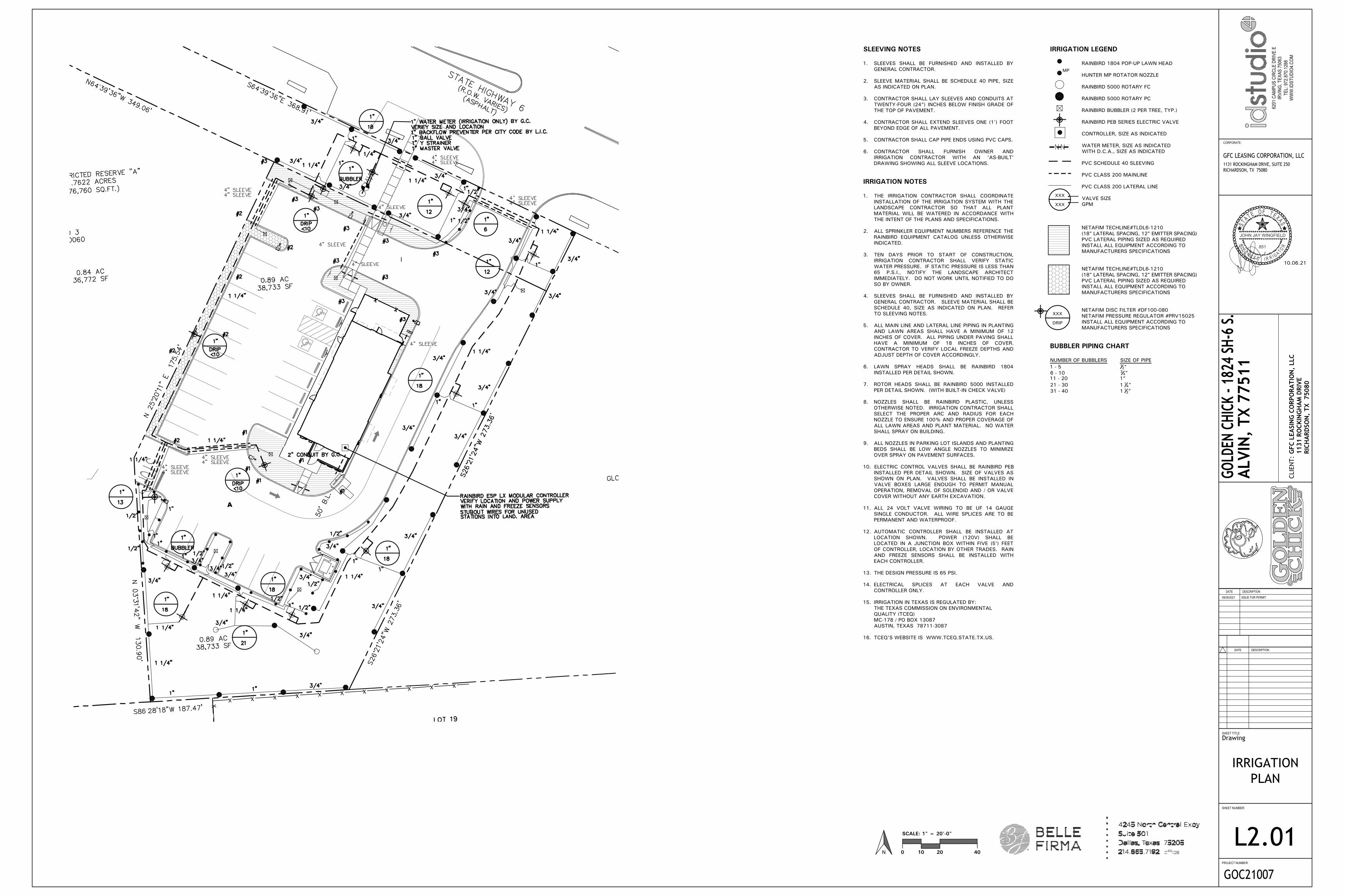
SLEEVING NOTES
1. SLEEVES SHALL BE FURNISHED AND INSTALLED BY
GENERAL CONTRACTOR.
2. SLEEVE MATERIAL SHALL BE SCHEDULE 40 PIPE, SIZE
AS INDICATED ON PLAN.
3. CONTRACTOR SHALL LAY SLEEVES AND CONDUITS AT
TWENTY-FOUR (24") INCHES BELOW FINISH GRADE OF
THE TOP OF PAVEMENT.
4. CONTRACTOR SHALL EXTEND SLEEVES ONE (1') FOOT
BEYOND EDGE OF ALL PAVEMENT.
5. CONTRACTOR SHALL CAP PIPE ENDS USING PVC CAPS.
6. CONTRACTOR SHALL FURNISH OWNER AND
IRRIGATION CONTRACTOR WITH AN 'AS-BUILT'
DRAWING SHOWING ALL SLEEVE LOCATIONS.
IRRIGATION NOTES
1. THE IRRIGATION CONTRACTOR SHALL COORDINATE
INSTALLATION OF THE IRRIGATION SYSTEM WITH THE
LANDSCAPE CONTRACTOR SO THAT ALL PLANT
MATERIAL WILL BE WATERED IN ACCORDANCE WITH
THE INTENT OF THE PLANS AND SPECIFICATIONS.
2. ALL SPRINKLER EQUIPMENT NUMBERS REFERENCE THE
RAINBIRD EQUIPMENT CATALOG UNLESS OTHERWISE
INDICATED.
3. TEN DAYS PRIOR TO START OF CONSTRUCTION,
IRRIGATION CONTRACTOR SHALL VERIFY STATIC
WATER PRESSURE. IF STATIC PRESSURE IS LESS THAN
65 P.S.I., NOTIFY THE LANDSCAPE ARCHITECT
IMMEDIATELY. DO NOT WORK UNTIL NOTIFIED TO DO
SO BY OWNER.
4. SLEEVES SHALL BE FURNISHED AND INSTALLED BY
GENERAL CONTRACTOR. SLEEVE MATERIAL SHALL BE
SCHEDULE 40, SIZE AS INDICATED ON PLAN. REFER
TO SLEEVING NOTES.
5. ALL MAIN LINE AND LATERAL LINE PIPING IN PLANTING
AND LAWN AREAS SHALL HAVE A MINIMUM OF 12
INCHES OF COVER. ALL PIPING UNDER PAVING SHALL
HAVE A MINIMUM OF 18 INCHES OF COVER.
CONTRACTOR TO VERIFY LOCAL FREEZE DEPTHS AND
ADJUST DEPTH OF COVER ACCORDINGLY.
6. LAWN SPRAY HEADS SHALL BE RAINBIRD 1804
INSTALLED PER DETAIL SHOWN.
7. ROTOR HEADS SHALL BE RAINBIRD 5000 INSTALLED
PER DETAIL SHOWN. (WITH BUILT-IN CHECK VALVE)
8. NOZZLES SHALL BE RAINBIRD PLASTIC, UNLESS
OTHERWISE NOTED. IRRIGATION CONTRACTOR SHALL
SELECT THE PROPER ARC AND RADIUS FOR EACH
NOZZLE TO ENSURE 100% AND PROPER COVERAGE OF
ALL LAWN AREAS AND PLANT MATERIAL. NO WATER
SHALL SPRAY ON BUILDING.
9. ALL NOZZLES IN PARKING LOT ISLANDS AND PLANTING
BEDS SHALL BE LOW ANGLE NOZZLES TO MINIMIZE
OVER SPRAY ON PAVEMENT SURFACES.
10. ELECTRIC CONTROL VALVES SHALL BE RAINBIRD PEB
INSTALLED PER DETAIL SHOWN. SIZE OF VALVES AS
SHOWN ON PLAN. VALVES SHALL BE INSTALLED IN
VALVE BOXES LARGE ENOUGH TO PERMIT MANUAL
OPERATION, REMOVAL OF SOLENOID AND / OR VALVE
COVER WITHOUT ANY EARTH EXCAVATION.
11. ALL 24 VOLT VALVE WIRING TO BE UF 14 GAUGE
SINGLE CONDUCTOR. ALL WIRE SPLICES ARE TO BE
PERMANENT AND WATERPROOF.
12. AUTOMATIC CONTROLLER SHALL BE INSTALLED AT
LOCATION SHOWN. POWER (120V) SHALL BE
LOCATED IN A JUNCTION BOX WITHIN FIVE (5') FEET
OF CONTROLLER, LOCATION BY OTHER TRADES. RAIN
AND FREEZE SENSORS SHALL BE INSTALLED WITH
EACH CONTROLLER.
13. THE DESIGN PRESSURE IS 65 PSI.
14. ELECTRICAL SPLICES AT EACH VALVE AND
CONTROLLER ONLY.
15. IRRIGATION IN TEXAS IS REGULATED BY:
THE TEXAS COMMISSION ON ENVIRONMENTAL
QUALITY (TCEQ)
MC-178 / PO BOX 13087
AUSTIN, TEXAS 78711-3087
16. TCEQ'S WEBSITE IS WWW.TCEQ.STATE.TX.US.
IRRIGATION LEGEND
RAINBIRD 1804 POP-UP LAWN HEAD
HUNTER MP ROTATOR NOZZLE
RAINBIRD 5000 ROTARY FC
RAINBIRD 5000 ROTARY PC
RAINBIRD BUBBLER (2 PER TREE, TYP.)
RAINBIRD PEB SERIES ELECTRIC VALVE
CONTROLLER, SIZE AS INDICATED
WATER METER, SIZE AS INDICATED
WITH D.C.A., SIZE AS INDICATED
PVC SCHEDULE 40 SLEEVING
PVC CLASS 200 MAINLINE
PVC CLASS 200 LATERAL LINE
VALVE SIZE
GPM
NETAFIM TECHLINE#TLDL6-1210
(18" LATERAL SPACING, 12" EMITTER SPACING)
PVC LATERAL PIPING SIZED AS REQUIRED
INSTALL ALL EQUIPMENT ACCORDING TO
MANUFACTURERS SPECIFICATIONS
NETAFIM TECHLINE#TLDL6-1210
(18" LATERAL SPACING, 12" EMITTER SPACING)
PVC LATERAL PIPING SIZED AS REQUIRED
INSTALL ALL EQUIPMENT ACCORDING TO
MANUFACTURERS SPECIFICATIONS
NETAFIM DISC FILTER #DF100-080
NETAFIM PRESSURE REGULATOR #PRV15025
INSTALL ALL EQUIPMENT ACCORDING TO
MANUFACTURERS SPECIFICATIONS
BUBBLER PIPING CHART
NUMBER OF BUBBLERS SIZE OF PIPE
1 - 5 12"
6 - 10 34"
11 - 20 1"
21 - 30 1 14"
31 - 40 1 12"
XXX
XXX
XXX
DRIP
MP
SHEET TITLE:
SHEET NUMBER:
PROJECT NUMBER:
GOC21007
DESCRIPTION
DESCRIPTIONDATE
DATE
CORPORATE:
GFC LEASING CORPORATION, LLC1131 ROCKINGHAM DRIVE, SUITE 250RICHARDSON, TX 75080
6201
CAM
PUS
CIRC
LE D
RIVE
EIR
VING
, TEX
AS 7
5063
TEL:
972
.870
.128
8W
WW
.IDST
UDIO
4.CO
MCL
IEN
T:
GOLD
EN C
HICK
- 18
24 SH
-6 S.
ALVI
N,
TX 7
7511
GFC
LEA
SIN
G C
ORP
ORA
TIO
N,
LLC
1131
RO
CKIN
GH
AM
DRI
VERI
CHA
RDSO
N,
TX 7
5080
ISSUE FOR PERMIT09/29/2021
10.06.21
STA T E O F T E XAS
L I C E N S E D I R GI A T OR
R
851
JOHN JAY WINGFIELD
Drawing
IRRIGATIONSPECIFICATIONS
AND DETAILS
L2.02
SECTION 32 8423 - UNDERGROUND IRRIGATION SLEEVES AND
UTILITY CONDUITS
PART 1 - GENERAL
1.1 DESCRIPTION
A. Provide underground irrigation sleeves as indicated on thedrawings.
1.2 RELATED WORK SPECIFIED ELSEWHERE
A. Section 32 8424 - Irrigation System
1.3 REFERENCED STANDARDS
A. American Society for Testing and Materials:
1. ASTM - D2441 Poly (Vinyl Chloride) (PVC) Plastic Pipe
(SD R-PR)
2. ASTM - D2466 Poly (Vinyl Chloride) (PVC) Plastic Pipe
Fittings, Socket Type, Schedule 40.
3. ASTM - D2564 Solvent Cements for Poly Vinyl Chloride
Plastic Pipe and Fittings.
PART 2 - MATERIALS
2.1 DEFINITIONS
A. Sleeve - A pipe within which another pipe is placed for
carrying water or other utilities to be installed.
B. Wire Sleeves - A pipe used to carry low voltage irrigation
wires for operation of the electric solenoid valves.
2.2 GENERAL
A. Polyvinyl Chloride Pipe (PVC) - Manufactured in accordance
with standards noted herein:
1. Marking and Identification - Permanently marked with
SDR number, ASTM standard number, and the NSF
(National Sanitation Foundation) seal.
2. Solvent - As recommended by manufacturer to make
solvent-welded joints. Thoroughly clean pipe and fittings
before applying solvent.
PART 3 - EXECUTION
3.1 INSTALLATION
A. Coverage - Provide twenty-four inches (24") minimum cover
over top of sleeve from finish grade.
B. Sleeve Extensions - Extend sleeves one foot (1') past edge of
pavement or concrete walls. Install 90 degree elbow on each
sleeve end and add additional length of same size pipe to
extend above finish grade by twelve inches (12"). Cap pipe
ends using duct tape.
3.2 BACKFILL
A. Compaction - Place backfill over sleeves in six (6") inch lifts.
Tamp firmly into place taking care not to damage sleeve.
Complete backfill and compaction to prevent any future
settlement. Compact to 85% Standard Proctor.
B. Damage - Repair any damage resulting from impropercompaction including pavement repair and replacement.
END OF SECTION
SECTION 32 8424 - IRRIGATION SYSTEM
PART 1 - GENERAL
1.1 SCOPE
A. Provide complete sprinkler installation as detailed andspecified herein, includes furnishing all labor, material, tools,
equipment, and related items for the complete and proper
installation of the irrigation system as indicated by theDrawings. All costs associated with this installation,
including fees for testing and inspections of the systemcomponents are the responsibility of the installer of this
irrigation system.
B. Work includes but is not limited to:
1. Trenching and backfill.
2. Installation of automatic controlled system.
3. Upon completion of installation, supply as-built drawings
showing details of construction including location ofmainline piping, manual and automatic valves, electrical
supply to valves, and specifically the exact location ofautomatic valves.
C. All sleeves as shown on plans shall be furnished by General
Contractor. Meter and power source shall be provided by
General Contractor.
1.2 RELATED WORK SPECIFIED ELSEWHERE
A. Refer to Irrigation Plans for controller, head, and valve
locations.
B. Section 32 8423 - Underground Irrigation Sleeves and Utility
Conduits
C. Section 32 9300 - Landscape
D. Refer to Landscape Plans, notes, details, bidding
requirements, special provisions, and schedules for additionalrequirements.
1.3 APPLICABLE STANDARDS
A. America Standard for Testing and Materials (ASTM) – Latest
edition.
1. D2241 Poly (Vinyl Chloride) (PVC) Plastic Pipe (SDR-PR)
2. D2464 Poly (Vinyl Chloride) (PVC) Plastic Pipe Fittings,
Thread, Schedule 80
3. D2455 Poly (Vinyl Chloride) (PVC) Plastic Pipe Fittings,
Schedule 40
4. D2467 Poly (Vinyl Chloride) (PVC) Plastic Pipe Fittings,
Socket Type, Schedule 80
5. D2564 Solvent Cements for Poly (Vinyl Chloride) (PVC)Plastic Pipe and Fittings
6. D2287 Flexible Poly Vinyl Chloride (PVC) Plastic Pipe
7. F656 Poly Vinyl Chloride (PVC) Solvent Weld Primer
8. D2855 Making Solvent – Cemented Joints with Poly
(Vinyl Chloride) (PVC) Pipe and Fittings
1.4 MAINTENANCE AND GUARANTEE
A. The Contractor shall guarantee materials and workmanship
for one (1) calendar year after final acceptance by Owner.
B. Guarantee is limited to repair and replacement of defective
materials or workmanship, including repair of backfill
settlement.
C. Provide maintenance of system, including raising and lowering
of heads to compensate for lawn growth, cleaning and
adjustment of heads, and raising and lowering of shrub headsto compensate for shrub growth for one (1) year after
completion of installation.
1.5 SUBMITTALS
A. Procedure: Comply with Division I requirements.
B. Product Data: The Contractor shall submit five (5) copies of
equipment manufacturer's 'cut sheets' and shop drawings for
approval by Owner Authorized Representative prior to
installation, including, but not limited to the following:
sprinkler head, pipe, controller, valves, backflow prevention
devices, valve boxes, wire, conduit, fittings, and all othertypes of fixtures proposed to be installed on the job. The
submittal shall include the manufacturer's name, model
number, equipment capacity, and manufacturer's installation
recommendations, if applicable, for each proposed item.
C. No work covered under this section may begin until the
Contractor has submitted the required information. No partial
submittal shall be accepted and submittals shall be neatly
bound into a brochure and logically organized. After thesubmittal has been approved, substitutions will not be
allowed, except by written consent by the Owner Authorized
Representative.
D. Shop drawings include dimensions, elevations, constructiondetails, arrangements, and capacity equipment, as well as
manufacturer's installation recommendations.
E. Operating and Maintenance Manuals:
1. Provide three (3) individually bound manuals detailing
operating and maintenance requirements for the irrigationsystem.
2. Manuals shall be delivered to the Owner Authorized
Representative no later than ten (10) days prior to
completion of the irrigation system.
3. Provide descriptions of all installed materials and systems
in sufficient detail to permit maintenance personnel to
understand, operate, and maintain the equipment.4. Provide the following in each manual:
a. Index sheet with Contractor's name, address,telephone number, and contact name.
b. Duration of guarantee period. Include warranties and
guarantees extended to the Owner by the
manufacturer of all equipment.c. Equipment list providing the following for each item:
1) Manufacturer's name
2) Make and model number
3) Name and address of local part's representative
4) Spare parts list in detail
5) Details operating and maintenance instructions for major equipment.
F. Project Record Documents:
1. Comply with Division I requirements.
2. Locate by written dimension, routing of mainline piping,
remote control valves, and quick coupling valves. Locatemainlines by single dimensions from permanent site
features provided they run parallel to these elements.Locate valves, intermediate electrical connections, and
quick couplers by two dimensions from a permanent site
feature at approximately 70 degrees to each other.
3. When dimensioning is complete, transpose work to bondpaper.
4. Submit three (3) copies of the completed as-built
drawings, along with a CD with PDF files of the same, to
the Owner Authorized Representative prior to final
acceptance of the work. Mark drawings “Record Prints
Showing Significant Changes”. Date and sign drawings.
G. Quick Coupler Keys: Provide three (3) coupler keys with
boiler drains attached using brass reducer.
H. Controller Keys: Provide three (3) sets of keys to controller
enclosure(s).
I. Use of materials differing in quality, size, or performance from
those specified shall only be allowed upon written approval ofthe Landscape Architect. The decision shall be based on
comparative ability of material or article to perform fully allpurposes of mechanics and general design considered to be
possessed by item specified.
J. Bidders desiring to make a substitution for specified sprinklers
shall submit manufacturer's catalog sheet showing fullspecification of each type sprinkler proposed as a substitute,
including discharge in GPM maximum allowable operating
pressure at sprinkler.
K. Approval of substitute sprinkler shall not relieve Irrigation
Contractor of his responsibility to demonstrate that final
installed sprinkler system shall operate according to intent of
originally designed and specified system.
L. It is the responsibility of the Irrigation Contractor to
demonstrate that final installed sprinkler system shall operate
according to intent of originally designed and specified
system. If Irrigation Contractor notes any problems in head
spacing or potential coverage, it is his responsibility to notifythe Landscape Architect in writing, before proceeding with
work. Irrigation Contractor guarantees 100% coverage of all
areas to be irrigated.
1.6 TESTING
A. Perform testing required with other trades, including
earthwork, paving, plumbing, electrical, etc., to avoidunnecessary cutting, patching, and boring.
B. Water Pressure: This irrigation system has been designed tooperate with a minimum static water pressure indicated on
Drawings. The Contractor shall take a pressure reading at
each water meter prior to beginning construction. Confirm
findings to Owner Authorized Representative in writing. If
static pressure varies from pressure stated on drawings, do
not start work until notified to do so by Owner Authorized
Representative.
1.7 COORDINATION
A. Coordinate installation with other trades, including earthwork,
paving, and plumbing to avoid unnecessary cutting, patchingand boring.
B. Coordinate to ensure that electrical power source is in place.
C. Coordinate system installation with work specified in other
sections and coordinate with Landscape Contractor to ensure
plant material is uniformly watered in accordance with intent
shown on drawings.
PART 2 - PRODUCTS
2.1 GENERAL
A. Mainline: Mainlines are the piping from water source to
operating valves. This portion of piping is subject to surges,
being a closed portion of sprinkler system. Hydrant lines are
considered a part of sprinkler main.
B. Lateral Piping: Lateral piping is that portion of piping from
operating valve to sprinkler heads. This portion of piping is
not subject to surges, being an "open end" portion ofsprinkler system.
2.2 POLY VINYL CHLORIDE PIPE (PVC PIPE)
A. PVC pipe shall be manufactured in accordance with
commercial standards noted herein.
B. Marking and Identification: PVC pipe shall be continuously
and permanently marked with the following information:
manufacturer's name, pipe size, type of pipe, and material,
SDR number, product standard number, and the NSF (National
Sanitation Foundation) seal.
C. PVC Pipe Fittings: Shall be of the same material as the PVC
pipe specified and shall be compatible with PVC pipe
furnished.
2.3 COPPER TUBING
A. Hard, straight lengths of domestic manufacture only. Do not
use copper tube of foreign extrusion or any so-called irrigationtubing (thin wall).
2.4 COPPER TUBE FITTINGS
A. Cast brass or wrought copper, sweat - solder type.
2.5 WIRE
A. Type UF with 4/64" thick waterproof insulation which is
Underwriter's Laboratory approved for direct underground
burial when used in a National Electric Code Class II Circuit
(30 volts AC or less).
B. Wire Connectors: Waterproof splice kit connectors. Type
DBY by 3M.
2.6 SCHEDULE 80 PVC NIPPLES
A. Composed of Standard Schedule 40 PVC Fittings and PVC
meeting noted standards. No clamps or wires may be used.
Nipples for heads and shrub risers to be nominal one-half inch
(12") diameter by eight (8") inches long, where applicable.
B. Polyethylene nipples six (6") inches long shall be used on all
pop-up spray heads.
2.7 MATERIALS - SEE IRRIGATION PLAN
A. Sprinkler heads in lawn area as specified on plan.
B. PVC Pipe: Class 200, SDR 21
C. Copper Tubing (City Connection): Type "M"
D. 24V Wire: Size 14, Type UF
E. Electric valves: Shall be all plastic construction as indicated
on plans.
F. Backflow Prevention Device: Refer to drawing requirements
and flow valve. Coordinate exact location with General
Contractor.
PART 3 - EXECUTION
3.1 INSTALLATION - GENERAL
A. Staking: Before installation is started, place a stake where
each sprinkler is to be located, in accordance with drawing.
Staking shall be approved by Owner Authorized
Representative before proceeding with work.
B. Excavations: Excavations are unclassified and include earth,
loose rock, rock or any combination thereof, in wet or drystate. Backfill trenches with material removed, provided that
the earth is suitable for compaction and contains no lumps,
clods rock, debris, etc. Special backfill specifications, iffurnished take preference over this general specification.
C. Backfill: Flood or hand-tamp to prevent after settling. Hand
rake trenches and adjoining area to leave grade in as good orbetter condition than before installation.
D. Piping Layout: Piping layout is diagrammatic. Route pipingaround trees and shrubs in such a manner as to avoid damageto plantings. Do not dig within ball of newly planted trees orshrubs. In areas where existing trees are present, trenches
shall be adjusted on-site to provide a minimum clearance of
four (4) feet between the drip line of any tree or trench. The
Contractor shall notify the Owner Authorized Representative
in writing of a planned change in trench routing from thatshown on the drawings.
3.2 PIPE INSTALLATION
A. Sprinkler Mains: Install a four (4") inch wide minimum trench
with a minimum of eighteen (18") inches of cover.
B. Lateral Piping: Install a four (4") inch wide minimum trench
deep enough to allow for installation of sprinkler heads and
valves, but in no case, with less than twelve (12") of cover.
C. Trenching: Remove lumber, rubbish, and large rocks from
trenches. Provide firm, uniform bearing for entire length ofeach pipe line to prevent uneven settlement. Wedging orblocking of pipe shall not be permitted. Remove foreign
matter or dirt from inside of pipe before welding, and keep
piping clean by approved means during and after laying ofpipe.
3.3 PVC PIPE AND FITTING ASSEMBLY
A. Solvent: Use only solvent recommended by manufacturer to
make solvent-welded joints. Thoroughly clean pipe andfittings of dirt, dust and moisture before applying solvent.
B. PVC to metal connection: Work metal connections first. Use
a non-hardening pipe dope such as Permatex No. 2 on
threaded PVC adapters into which pipe may be welded.
3.4 COPPER TUBING AND FITTING ASSEMBLY
A. Clean pipe and fitting thoroughly and lightly sand pipe
connections to remove residue from pipe. Attach fittings to
tubing in an approved manner using 50-50 soft solid core
solder.
3.5 POP-UP SPRAY HEADS
A. Supply pop-up spray heads in accordance with materials list
and plan. Attach sprinkler to lateral piping with a
semi-flexible polyethylene nipple not less than three (3")
inches or more than six (6") inches long.
3.6 VALVES
A. Supply valves in accordance with materials list and sized
according to drawings. Install valves in a level position in
accordance with manufacturer's specifications. See plan for
typical installation of electric valve and valve box.
3.7 WIRING
A. Supply wire from the automatic sprinkler controls to the
valves. No conduit will be required for UF wire unlessotherwise noted on the plan. Wire shall be tucked under thepiping.
B. A separate wire is required from the control to each electricvalve. A common neutral wire is also required from each
control to each of the valves served by each particular
control.
C. Bundle multiple wires and tape them together at ten (10')
foot intervals. Install ten (10") inch expansion coils at not
more than one hundred (100') foot intervals. Make splices
waterproof.
3.8 AUTOMATIC SPRINKLER CONTROLS
A. Supply in accordance with Irrigation Plan. Install according to
manufacturer's recommendations.
3.9 TESTING
A. Sprinkler Mains: Test sprinkler main only for a period of
twelve (12) to fourteen (14) hours under normal pressure. If
leaks occur, replace joint or joints and repeat test.
B. Complete tests prior to backfilling. Sufficient backfill material
may be placed in trenches between fittings to ensure stabilityof line under pressure. In each case, leave fittings and
couplings open to visual inspection for full period of test.
3.10 FINAL ADJUSTMENT
A. After installation has been completed, make final adjustment
of sprinkler system in preparation for Owner Authorized
Representative's final inspection.
B. Completely flush system to remove debris from lines byremoving nozzle from heads on end of lines and turning onsystem.
C. Check sprinklers for proper operation and proper alignment for
direction of throw.
D. Check each section of spray heads for operating pressure and
balance to other sections by use of flow adjustment on top ofeach valve.
E. Check nozzling for proper coverage. Prevailing wind
conditions may indicate that arch of angle of spray should beother than shown on drawings. In this case, change nozzles
to provide correct coverage and furnish data to OwnerAuthorized Representative with each change.
3.11 SYSTEM DEMONSTRATION
A. Instruct Owner's personnel in operation and maintenance ofsystem including adjusting of sprinkler heads. Use operation
and maintenance manual for basis of demonstration.
END OF SECTION
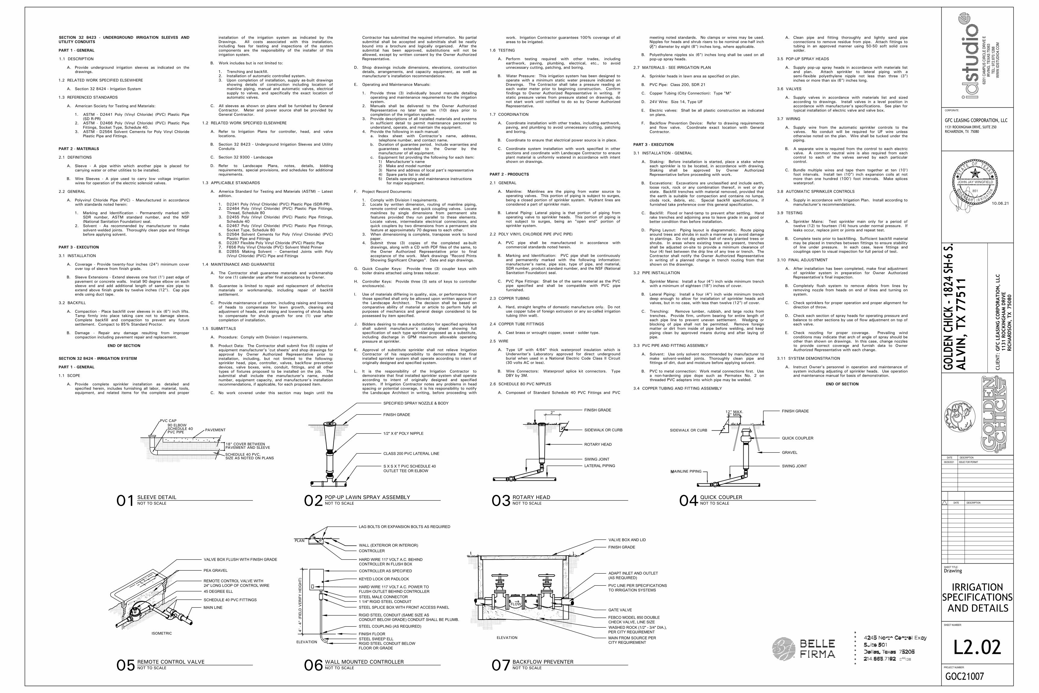
FINISH GRADE2"
HARD WIRE 117 VOLT A.C. BEHINDCONTROLLER IN FLUSH BOX
01SLEEVE DETAILNOT TO SCALE
ISOMETRIC
6" MIN.
MAINLINE PIPINGM
SIDEWALK OR CURB
4'
- 4" (
FIE
LD
VERIF
Y H
EIG
HT)
ELEVATION
12" MAX.
PLAN
ELEVATION
FLOW
PAVEMENTSCHEDULE 4090 ELBOW
PVC PIPE
PVC CAP
PAVEMENT AND SLEEVE18" COVER BETWEEN
SIZE AS NOTED ON PLANSSCHEDULE 40 PVC,
02POP-UP LAWN SPRAY ASSEMBLYNOT TO SCALE 03
ROTARY HEADNOT TO SCALE 04
QUICK COUPLERNOT TO SCALE
07BACKFLOW PREVENTERNOT TO SCALE06
WALL MOUNTED CONTROLLERNOT TO SCALE05
REMOTE CONTROL VALVENOT TO SCALE
VALVE BOX FLUSH WITH FINISH GRADE
PEA GRAVEL
REMOTE CONTROL VALVE WITH24" LONG LOOP OF CONTROL WIRE45 DEGREE ELL
SCHEDULE 40 PVC FITTINGS
MAIN LINE
SPECIFIED SPRAY NOZZLE & BODY
FINISH GRADE
1/2" X 6" POLY NIPPLE
CLASS 200 PVC LATERAL LINE
S X S X T PVC SCHEDULE 40OUTLET TEE OR ELBOW
LAG BOLTS OR EXPANSION BOLTS AS REQUIRED
WALL (EXTERIOR OR INTERIOR)CONTROLLER
CONTROLLER AS SPECIFIED
KEYED LOCK OR PADLOCK
HARD WIRE 117 VOLT A.C. POWER TOFLUSH OUTLET BEHIND CONTROLLERSTEEL MALE CONNECTOR1 1/4" RIGID STEEL CONDUITSTEEL SPLICE BOX WITH FRONT ACCESS PANEL
RIGID STEEL CONDUIT (SAME SIZE ASCONDUIT BELOW GRADE) CONDUIT SHALL BE PLUMB.
STEEL COUPLING (AS REQUIRED)
FINISH FLOORSTEEL SWEEP ELLRIGID STEEL CONDUIT BELOWFLOOR OR GRADE
VALVE BOX AND LID
FINISH GRADE
ADAPT INLET AND OUTLET(AS REQUIRED)
PVC LINE PER SPECIFICATIONSTO IRRIGATION SYSTEMS
GATE VALVE
FEBCO MODEL 850 DOUBLECHECK VALVE, LINE SIZEWASHED ROCK (1/2" - 3/4" DIA.),PER CITY REQUIREMENTMAIN FROM SOURCE PERCITY REQUIREMENT
FINISH GRADE
SIDEWALK OR CURB
ROTARY HEAD
SWING JOINT
LATERAL PIPING
QUICK COUPLER
GRAVEL
SWING JOINT