Embed Size (px)
Citation preview
STUDIES OF ANODE SUPPORTED SOLID OXIDE FUEL CELLS
(SOFCS) BASED ON LA- AND CA-DOPED SRTIO₃
Lanying Lu
A Thesis Submitted for the Degree of PhDat the
University of St Andrews
2015
Full metadata for this item is available inSt Andrews Research Repository
athttpresearch-repositoryst-andrewsacuk
Please use this identifier to cite or link to this itemhttphdlhandlenet100237068
This item is protected by original copyright
This item is licensed under aCreative Commons Licence
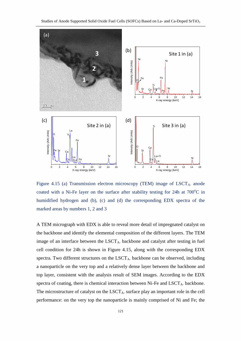
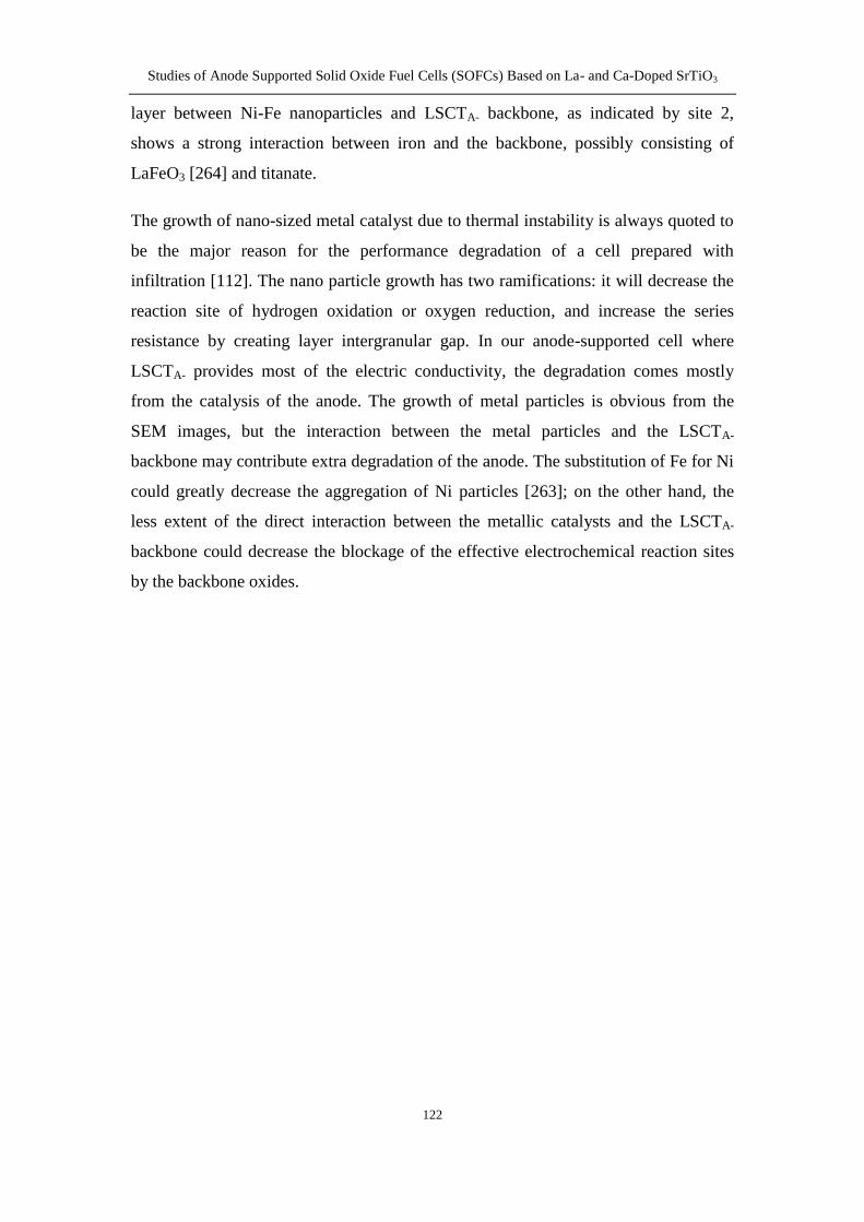
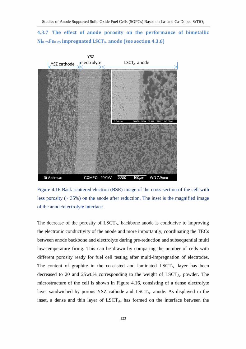
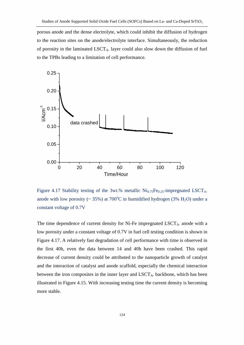
Studies of Anode Supported Solid Oxide Fuel Cells (SOFCs) Based on La- and Ca-Doped SrTiO3
Lanying Lu
This thesis is submitted in partial fulfilment for the degree of PhD
at the University of St Andrews
Submitted January 2015
I
Declarations
I Lanying Lu hereby certify that this thesis which is approximately 52000 words in
length has been written by me and that it is the record of work carried out by me or
principally by myself in collaboration with others as acknowledged and that it has not
been submitted in any previous application for a higher degree
I was admitted as a research student in October 2011 and as a candidate for the degree
of Doctor of Philosophy in October 2014 the higher study for which this is a record
was carried out in the University of St Andrews between 2011 and 2014
Date helliphellip signature of candidate helliphelliphellip
I hereby certify that the candidate has fulfilled the conditions of the Resolution and
Regulations appropriate for the degree of Doctor of Philosophy in the University of St
Andrews and that the candidate is qualified to submit this thesis in application for that
degree
Date helliphellip signature of supervisorhelliphelliphellip
Date helliphellip signature of supervisor helliphelliphellip
In submitting this thesis to the University of St Andrews I understand that I am giving
permission for it to be made available for use in accordance with the regulations of
the University Library for the time being in force subject to any copyright vested in
the work not being affected thereby I also understand that the title and the abstract
will be published and that a copy of the work may be made and supplied to any bona
fide library or research worker that my thesis will be electronically accessible for
personal or research use unless exempt by award of an embargo as requested below
and that the library has the right to migrate my thesis into new electronic forms as
required to ensure continued access to the thesis I have obtained any third-party
copyright permissions that may be required in order to allow such access and
migration or have requested the appropriate embargo below
The following is an agreed request by candidate and supervisors regarding the
publication of this thesis
Access to printed copy but embargo on electronic copy for a period of 2 years on the
following ground
Publication would preclude future publication
Date helliphellip signature of candidate helliphellip
Date helliphellip signature of supervisor helliphelliphellip
Date helliphellip signature of supervisor helliphelliphellip
II
Acknowledgements
First and foremost I would like to sincerely thank my supervisors Prof John Irvine
and Dr Mark Cassidy for giving me the opportunity to work as a PhD student in the
research filed of solid oxide fuel cells My knowledge and experience on solid oxide
fuel cells were quite minimal before I started this project but they have been always
patient to me and responded to my queries associated with the laboratory work and
data analysis very promptly Their support trust and profound knowledge are
definitely the most essential factors for the completion of my thesis Without their
involvement I would never be capable of finishing my thesis
I would like to thank all the members of the JTSI group for the help with testing
instruments and result discussion during my three years in St Andrews In particular I
want to show my deep gratitude to Dr Maarten Verbraeken for teaching me the slurry
preparation and tape casting technique Dr David Miller for the TEM and EDX
analysis on my samples and Dr Mark Cassidy for the kind help on screen printing
technique I also acknowledge Mrs Julie Nairn and Dr Paul Conner who helped me a
lot in the lab Mrs Sylvia Williamson who taught me to operate TGA and dilatometer
and Mr Ross Blackley for the demonstration of SEM equipments
My deepest gratitude goes to Mr Alan Davidson in Napier University Edinburgh for
his supervision and guidance on the work about Ni-YSZ anode fabrication using the
electroless Ni-YSZ co-deposition process Special thanks to Dr Callum Wilson Dr
Neil Shearer and Mr Dong Wang for the lab-related work and discussion
My thanks also to MCS company Edinburgh that collaborated with my research Mr
Stewart McCracken Dr Andrew Gibson and Dr Stephen Mee have helped me to slot
my samples for FIB preparation even when the cutting system was extremely busy
and spared their time for my manuscript correction
I would like to grant my special thanks to my family for all the help and support
throughout my study Although being far away my parents have encouraged me to
pursue my PhD study all the time To my husband Dr Chengsheng Ni who always
stood by me even at the bad times and gave me his best suggestions about my
experimental analysis Without their intrinsic love and inspiration I would not be able
to conquer the difficulties I have encountered for the completion of my thesis
The last but not the least I would like to express my gratitude to the Fuel Cells and
Hydrogen Joint Technology Initiative and Energy Technology Partnership (ETP) for
funding that supports me throughout my PhD journey
III
Abstract
Solid oxide fuel cells (SOFCs) have attracted much interest as the most efficient
electrochemical device to directly convert chemical energy to usable electrical energy
The porous Ni-YSZ anode known as the state-of-the-art cermet anode material is
found to show serious degradation when using hydrocarbon as fuel due to carbon
deposition sulphur poisoning and nickel sintering In order to overcome these
problems doped strontium titanate has been investigated as a potential anode material
due to its high electronic conductivity and stability in reducing atmosphere In this
work A-site deficient strontium titanate co-doped with lanthanum and calcium
La02Sr025Ca045TiO3 (LSCTA-) was examined
Flat multilayer ceramics have been produced using the aqueous tape casting technique
by controlling the sintering behaviour of LSCTA- resulting in a 450microm thick porous
LSCTA- scaffold with a well adhered 40microm dense YSZ electrolyte Impregnation of
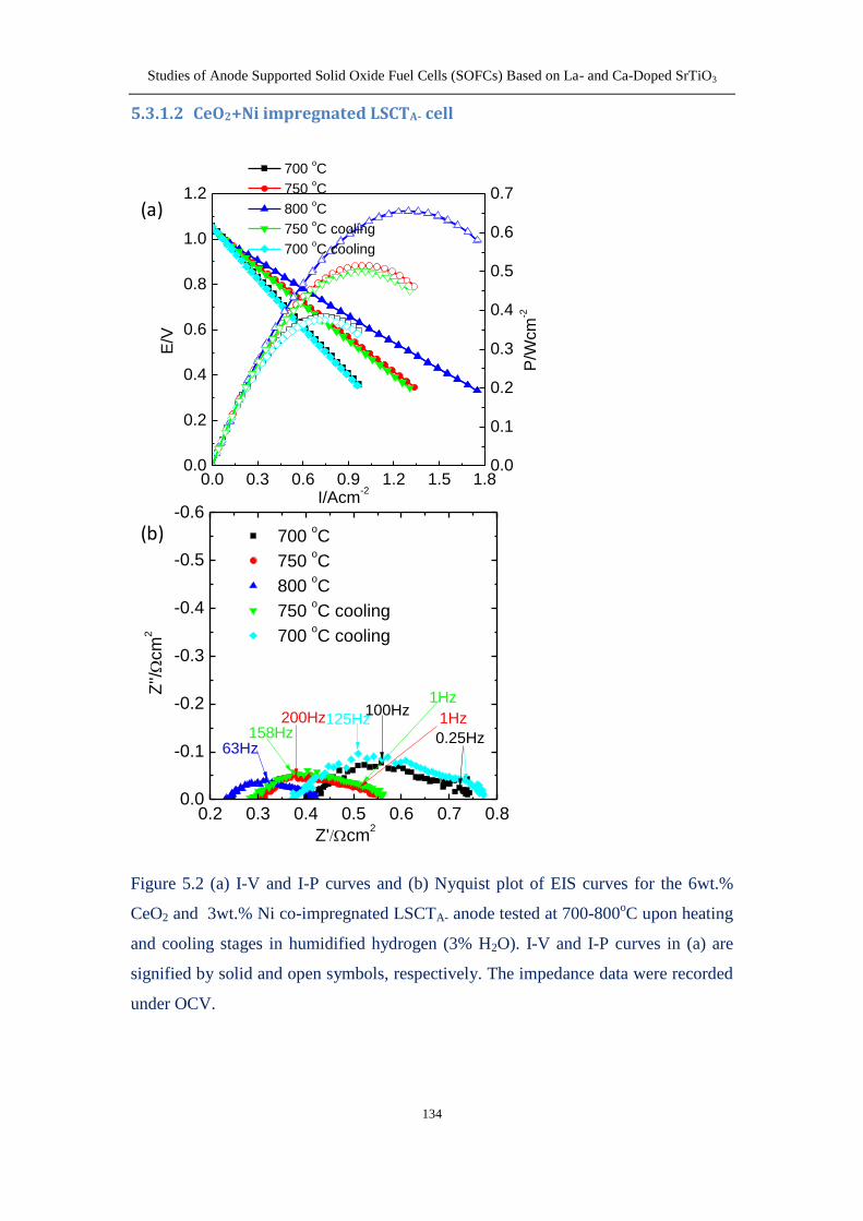
CeO2 and Ni results in a maximum power density of 096Wcm-2
at 800oC higher than
those of without impregnation (0124Wcm-2
) and with impregnation of Ni alone
(037Wcm-2
) The addition of catalysts into LSCTA- anode significantly reduces the
polarization resistance of the cells suggesting an insufficient electrocatalytic activity
of the LSCTA- backbone for hydrogen oxidation but LSCTA- can provide the
electronic conductivity required for anode
Later the cells with the configuration of LSCTA-YSZLSCF-YSZ were prepared by
the organic tape casting and impregnation techniques with only 300-m thick anode
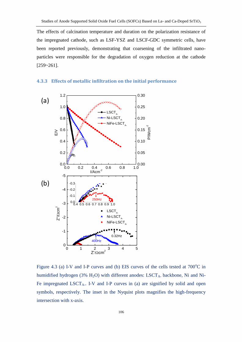
as support The effects of metallic catalysts in the anode supports on the initial
performance and stability in humidified hydrogen were discussed The nickel and iron
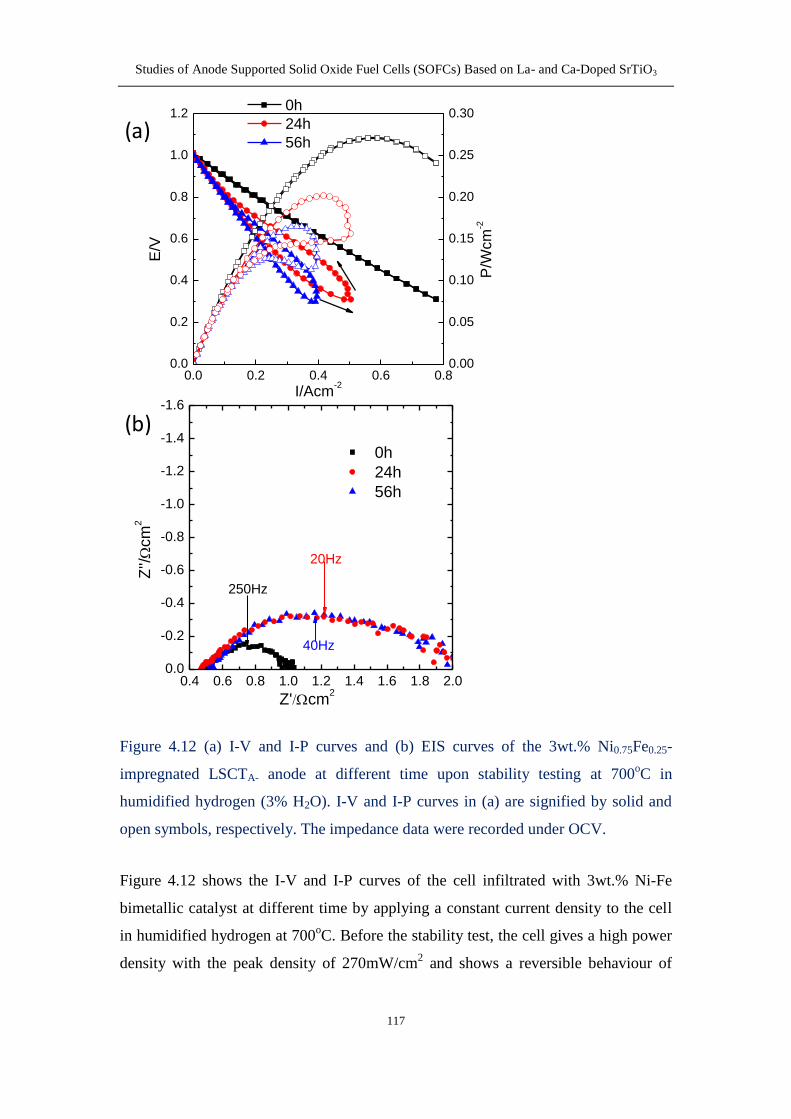
impregnated LSCTA- cell exhibits a maximum powder density of 272mWcm2 at
700oC much larger than 43mWcm
2 for the cell without impregnation and
112mWcm2 for the cell with nickel impregnation Simultaneously the bimetal Ni-Fe
impregnates have significantly reduced the degradation rates in humidified hydrogen
(3 H2O) at 700oC The enhancement from impregnation of the bi-metal can possibly
be the result of the presence of ionic conducting Wustite Fe1-xO that resides
underneath the Ni-Fe metallic particles and better microstructure
IV
Third in order to improve the ionic conductivity of the anode support and increase the
effective TPBs ionic conducting ceria was impregnated into the LSCTA- anode along
with the metallic catalysts The CeO2-LSCTA- cell shows a poor performance upon
operation in hydrogen atmosphere containing 3 H2O and with addition of metallic
catalysts the cell performance increases drastically by almost three-fold However
the infiltrated Ni particles on the top of ceria layer cause the deposition of carbon
filament leading to cell cracking when exposure to humidified methane (3 H2O) No
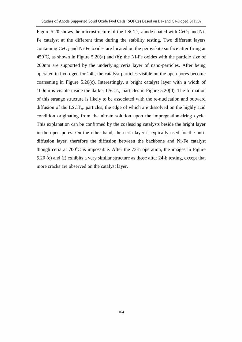
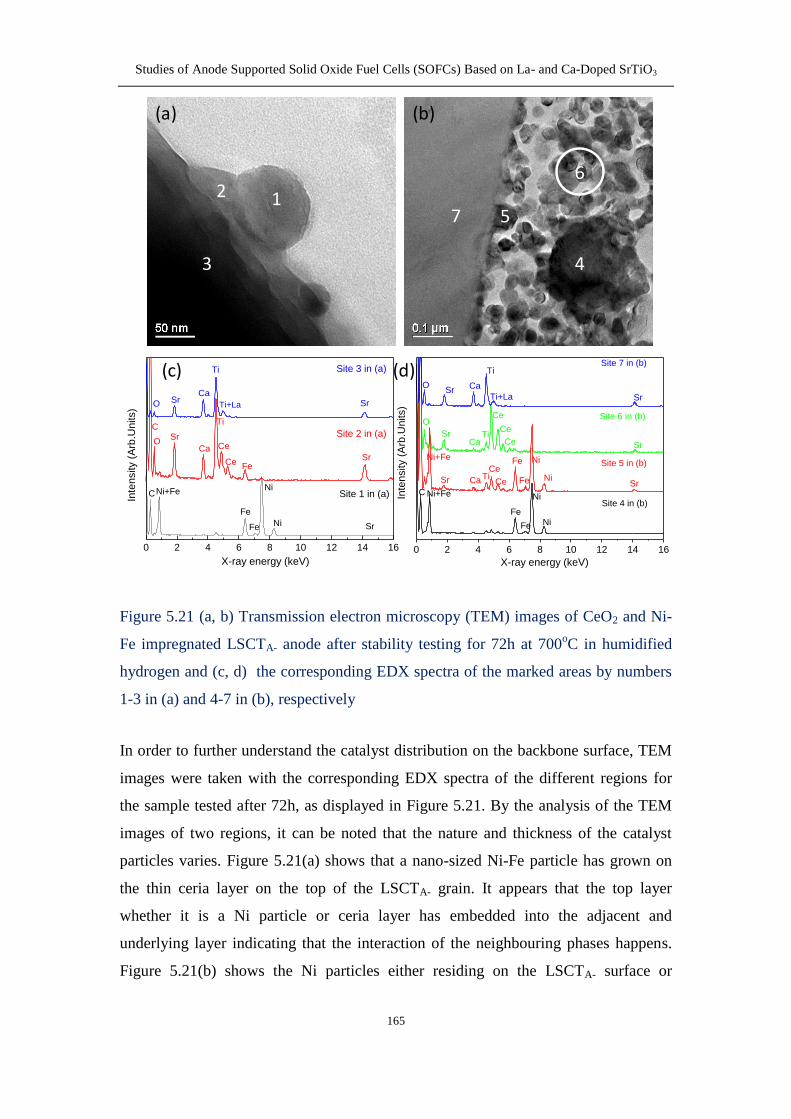
such behaviour was observed on the CeO2-NiFe impregnated anode The
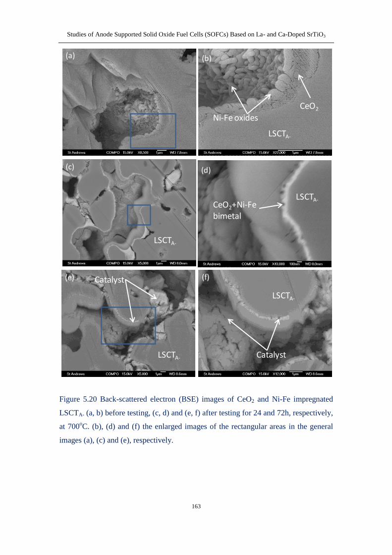
microstructure images of the impregnated anodes at different times during stability
testing demonstrate that the grain growth of catalysts the interaction between the
anode backbone and infiltrates and the spalling of the agglomerated catalysts are the
main reasons for the performance degradation
Fourth the YSZ-LSCTA- composites including the YSZ contents of 5-80wt were
investigated to determine the percolation threshold concentration of YSZ to achieve
electronic and ionic conducting pathways when using the composite as SOFC anode
backbone The microstructure and dilatometric curves show that when the YSZ
content is below 30 the milled sample has a lower shrinkage than the unmilled one
due to the blocking effect from the well distributed YSZ grains within LSCTA- bulk
However at the YSZ above 30 where two phases start to form the individual and
interconnected bulk the composites without ball milling process show a lower
densification The impact of YSZ concentration and ball milling process on the
electrical properties of the composites reveals that the percolation threshold
concentration is not only dependant on the actual concentration but also related to the
local arrangement of two phases
In Napier University the electroless nickel-ceramic co-depositon process was
investigated as a manufacturing technique for the anodes of planar SOFCs which
entails reduced costs and reduced high-temperature induced defects compared with
conventional fabrication techniques The Ni-YSZ anodes prepared by the electroless
co-deposition technique without the addition of surfactant adhere well to the YSZ
electrolyte before and after testing at 800oC in humidified hydrogen Ni-YSZ anodes
co-deposited with pore-forming starch showed twice the maximum power density
compared with those without the starch It has therefore been demonstrated that a
V
porous Ni-YSZ cermet structure was successfully manufactured by means of an
electroless plating technique incorporating pore formers followed by firing at 450oC
in air Although the use of surfactant (CTAB) increases the plating thickness it
induces the formation of a Ni-rich layer on the electrolyteanode interface leading to
the delamination of anode most likely due to the mismatched TECs with the adjacent
YSZ electrolyte
VI
Abbreviations
8YSZ 8mol yttria doped zirconia
AFC alkaline fuel cell
ASR area specific resistance
BET brunauerndashemmettndashteller
BSE backscattered electron
BZCYYb BaZr01Ce07Y01Yb01O3-δ
CPE constant phase element
CTAB cetyltrimethyl ammonium bromide
DBP di-n-butyl phthalate
EDS energy dispersive x-ray spectroscopy
EIS electrochemical impedance spectroscopy
EMF electromotive force
EN electroless nickel
FEG field emission gun
FIB focused ion beam
GDCCGO gadolinia-doped ceria
HF high frequency
I-P current-power
I-V current-voltage
LF low frequency
LSBT La04Sr06-xBaxTiO3 (0ltxle02)
LSC strontium-doped lanthanum cobalt
LSCF lanthanum strontium cobalt ferrite
LSCTA- A-site deficient lanthanum strontium calcium titanate
LSCX La075Sr025Cr05X05O3-δ (X=Co Fe Ti Mn)
LSF strontium-doped lanthanum ferrite
LSGM lanthanum strontium gallium magnesium oxide
LSM strontium-doped lanthanum manganite
LST lanthanum-doped SrTiO3
LSTC La and Cr co-doped SrTiO3
LSTCo Co-doping in B site on LST
LSTM Mn-doping in B site on LST
LVDT linear variable displacement transducer
MCFC molten carbonate fuel cell
MIEC mixed ionic and electronic conductor
OCV open circuit voltage
PAFC phosphoric acid fuel cell
PEG poly(ethylene glycol)
PEMFC polymer electrolyte membrane fuel cell
PSA particle size analysis
VII
PVA polyvinyl alcohol
PVB polyvinyl butyral
redox reduction-oxidation
RT room temperature
ScSZ scandia stabilized zirconia
SDC samaria-doped ceria
SEM scanning electron microscopy
SOFC solid oxide fuel cell
SSA specific surface area
SSC Sm05Sr05CoO3
STF iron-doped SrTiO3
STN niobiumndashdoped SrTiO3
STO strontium titanium oxide
TEC thermal expansion coefficient
TEM transmission electron microscopy
TGA thermal gravimetric analysis
TPB triple phase boundary
XRD x-ray diffraction
YST yttrium-doped SrTiO3
YSTCo Co-doping in B site on YST
YSZ yttria-stabilized zirconia
VIII
Contents
Declarations I
Acknowledgements II
Abstract III
Abbreviations VI
Contents VIII
Chapter 1 Introduction 1
11 Fuel cell technology 1
111 Definition 1
112 History 2
113 Classification of fuel cells 2
114 Advantages 4
12 Basics of solid oxide fuel cells 5
121 Principles of operation 5
122 Thermodynamic principles of SOFCs 6
123 Configuration and evolution of SOFCs 8
13 Electrolyte materials for SOFCs 9
14 Cathode materials for SOFCs 12
15 Anode materials for SOFCs 15
151 Requirements for anode 15
152 Ni-YSZ cermet anodes 16
153 Modified Ni-YSZ based anodes 18
154 SrTiO3 (STO)-based perovskite anodes 20
1541 A-site doped SrTiO3 21
1542 B-site doped SrTiO3 23
1543 A- and B-site co-doped SrTiO3 24
16 Direct oxidation of hydrocarbon 26
17 Infiltrationimpregnation method 28
18 Objective of the work 29
Chapter 2 Experimental techniques 32
21 Cell fabrication techniques 32
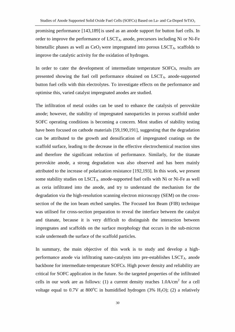
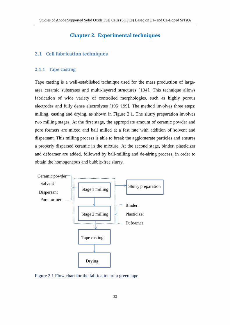
211 Tape casting 32
IX
212 Screen printing 34
213 Infiltrationimpregnation 36
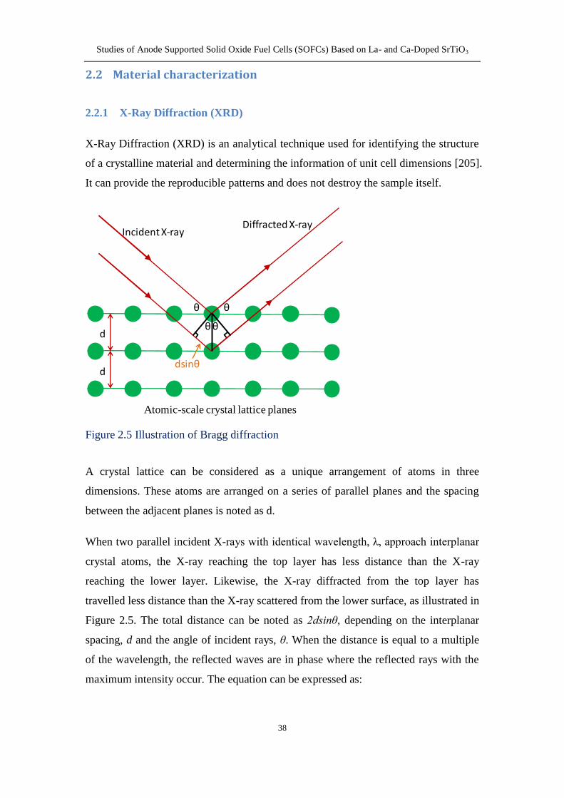
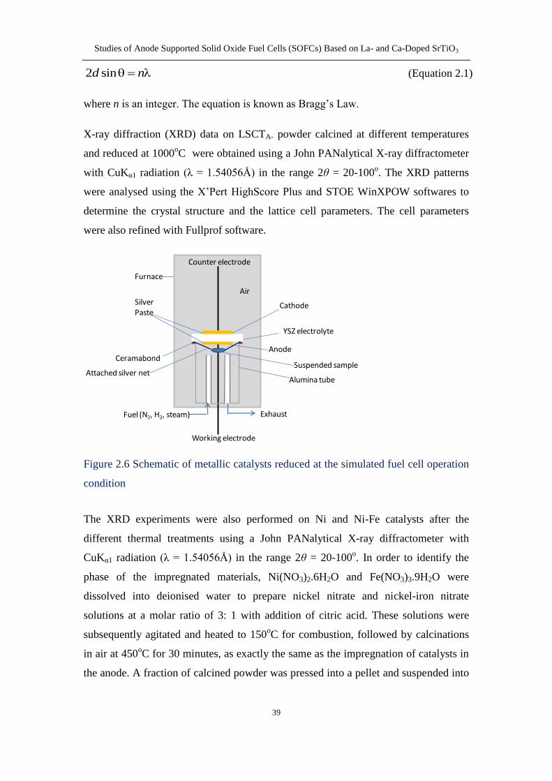
22 Material characterization 38
221 X-Ray Diffraction (XRD) 38
222 Scanning Electron Microscopy (SEM) and Back-Scattered Electron
(BSE) 40
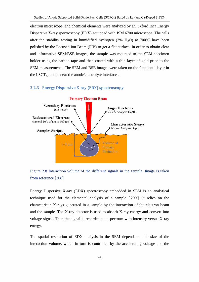
223 Energy Dispersive X-ray (EDX) spectroscopy 42
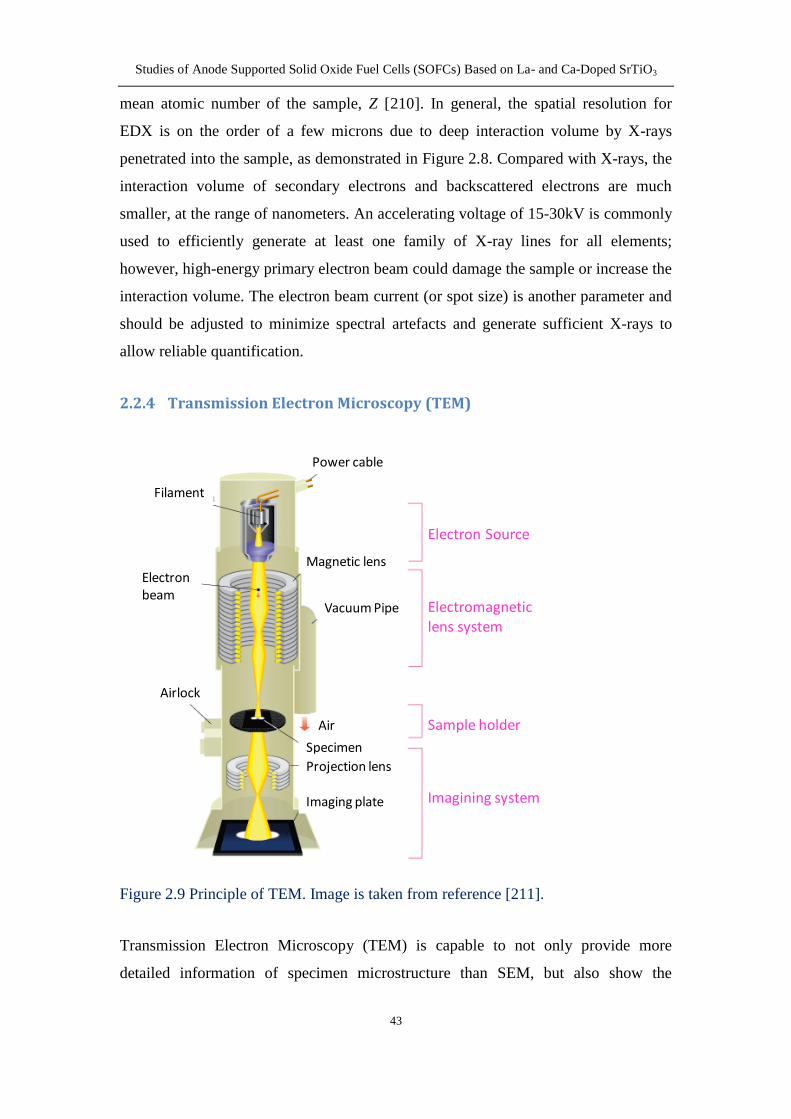
224 Transmission Electron Microscopy (TEM) 43
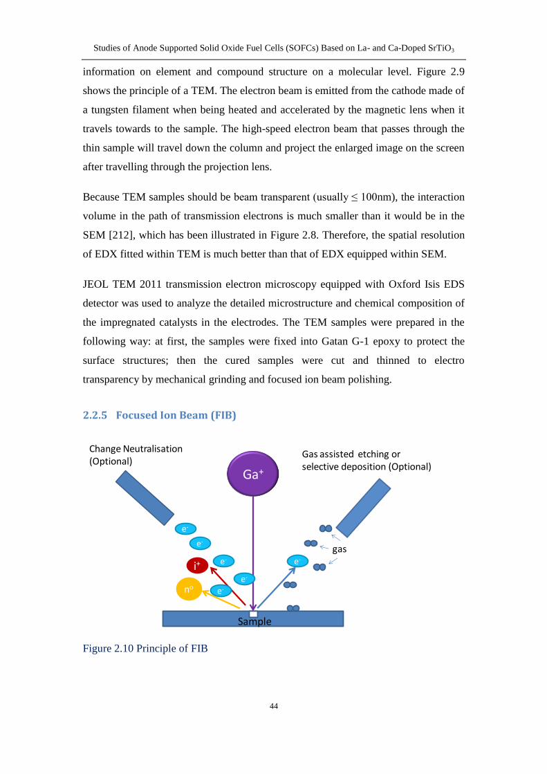
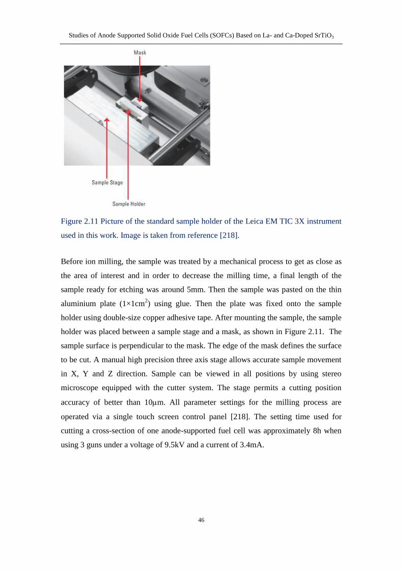
225 Focused Ion Beam (FIB) 44
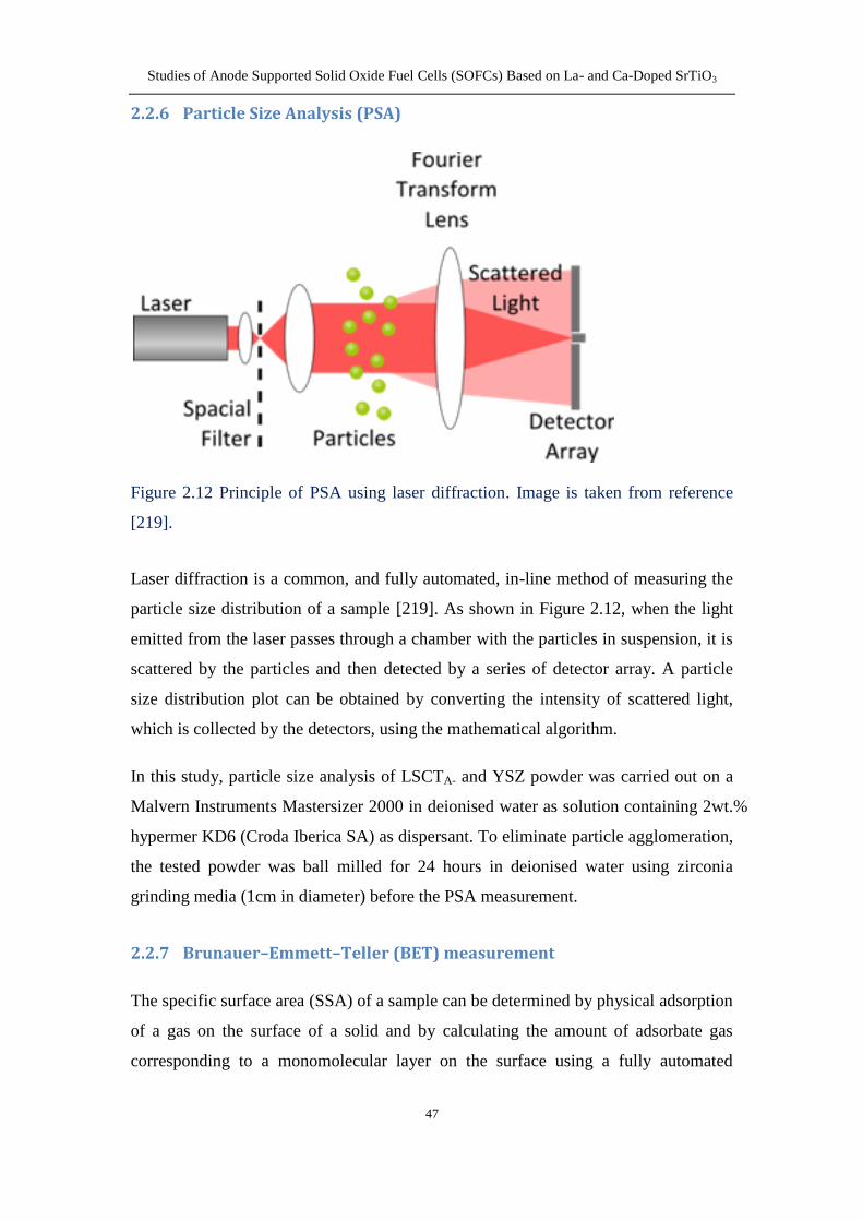
226 Particle Size Analysis (PSA) 47
227 BrunauerndashEmmettndashTeller (BET) measurement 47
228 Dilatometry 48
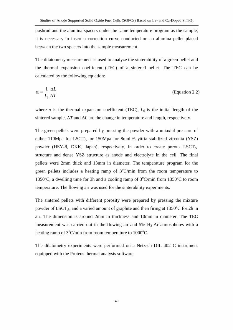
229 Thermal Gravimetric Analysis (TGA) 50
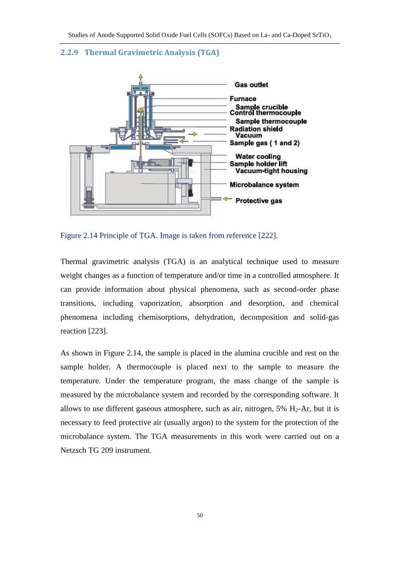
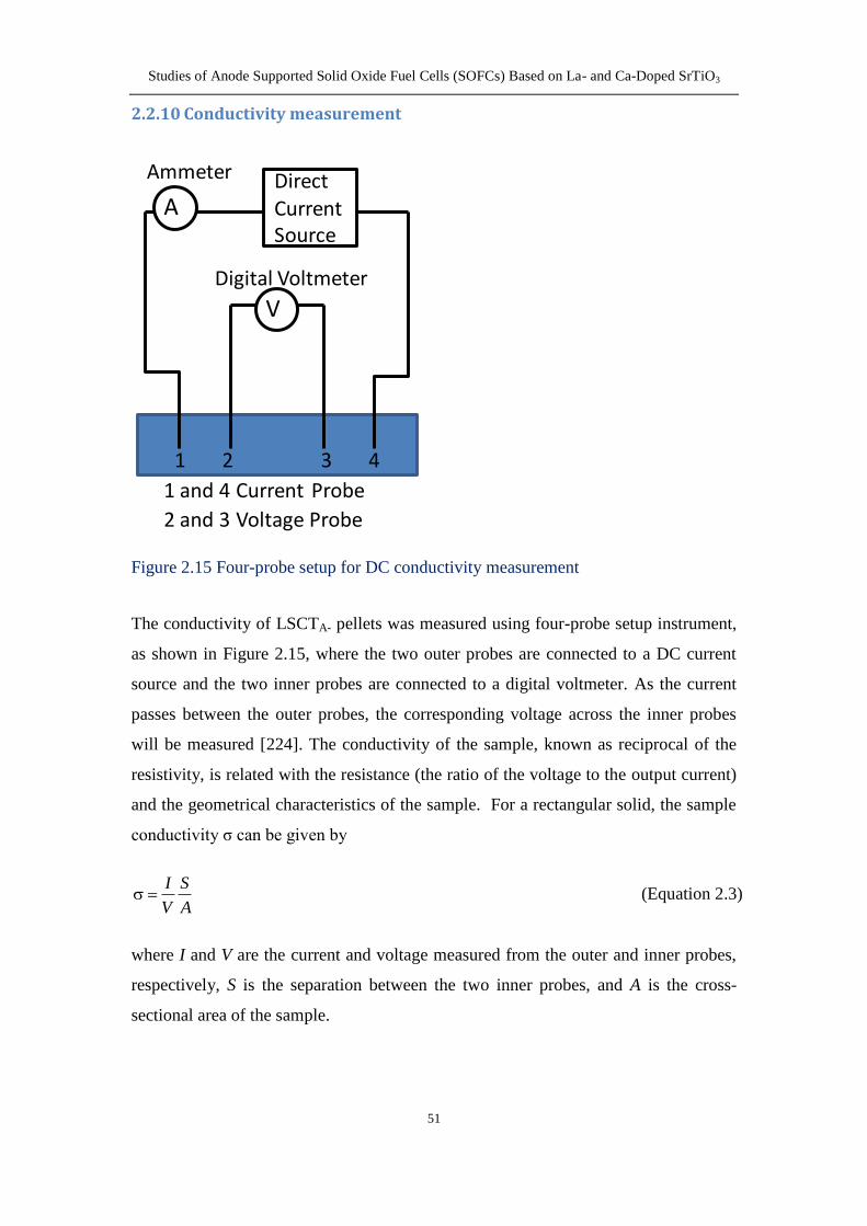
2210 Conductivity measurement 51
23 Electrochemical testing techniques 52
231 Two-electrode four-probe testing setup 52
232 Current-Voltage (I-V) measurement 53
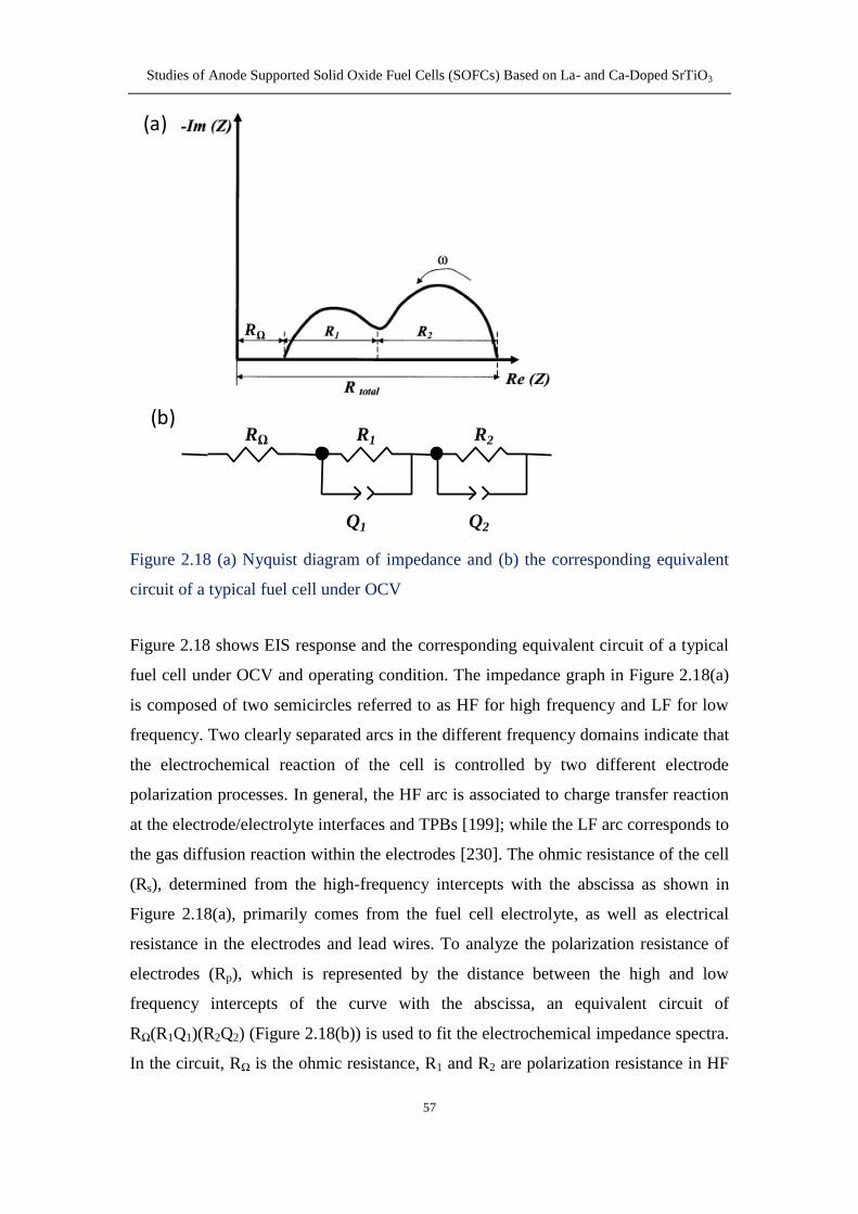
233 Electrochemical Impedance Spectroscopy (EIS) 54
2331 AC impedance 54
2332 Equivalent circuit 55
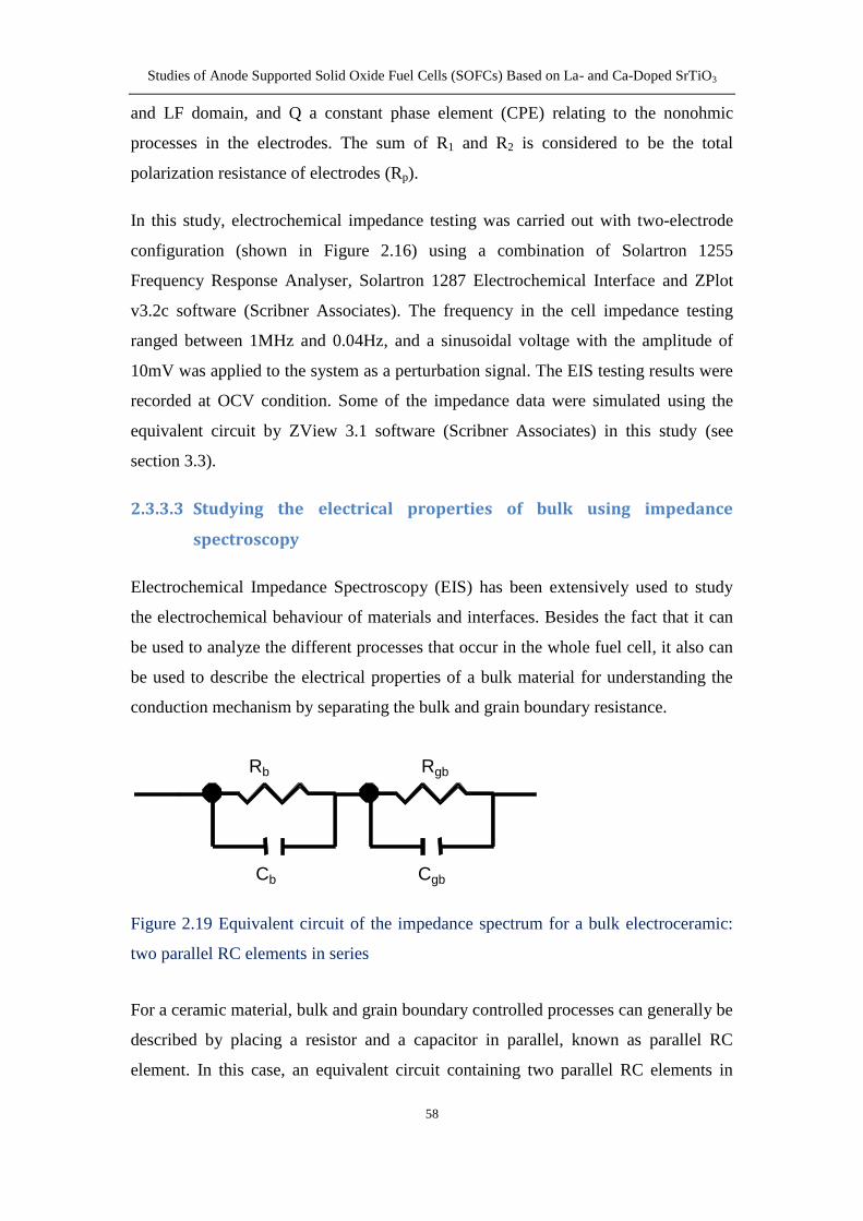
2333 Studying the electrical properties of bulk using impedance
spectroscopy 58
Chapter 3 Characterization of LSCTA- powder and its initial performance
for anode-supported SOFCs prepared by aqueous tape casting 62
31 Characterization of LSCTA- powder 62
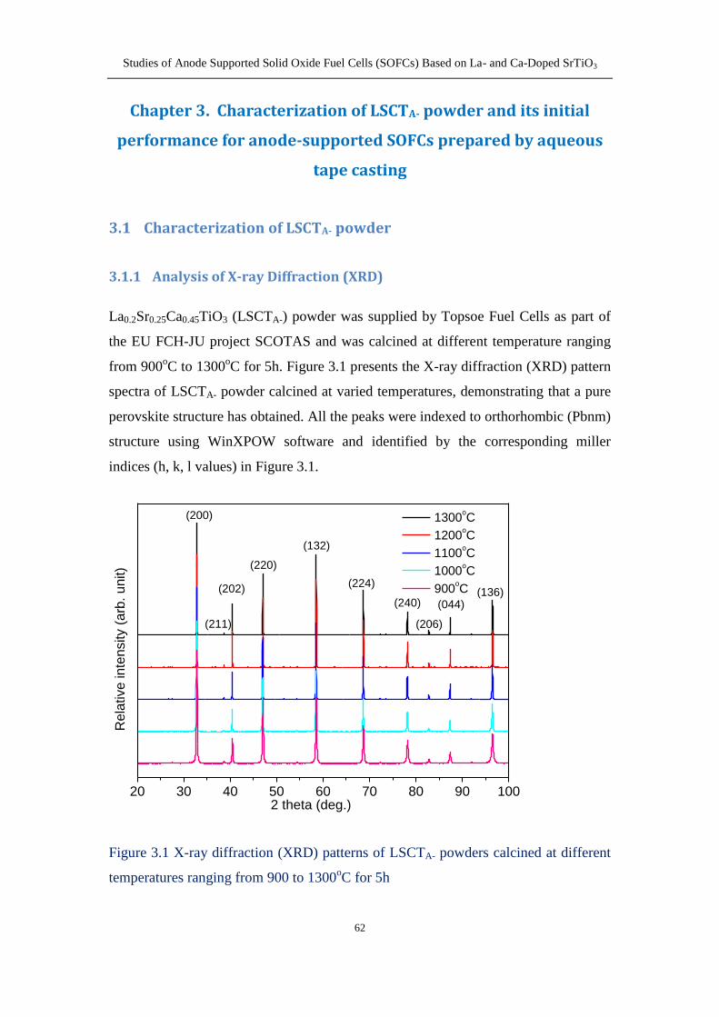
311 Analysis of X-ray Diffraction (XRD) 62
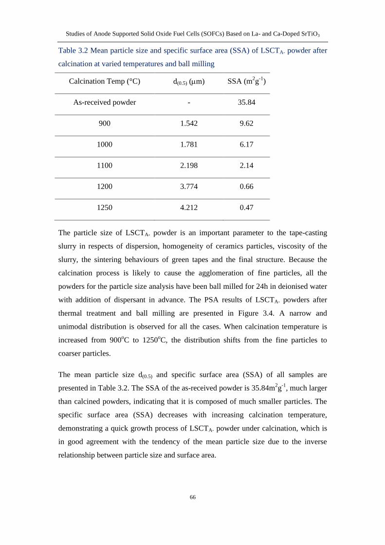
312 Particle Size Analysis (PSA) and Specific Surface Area (SSA) 65
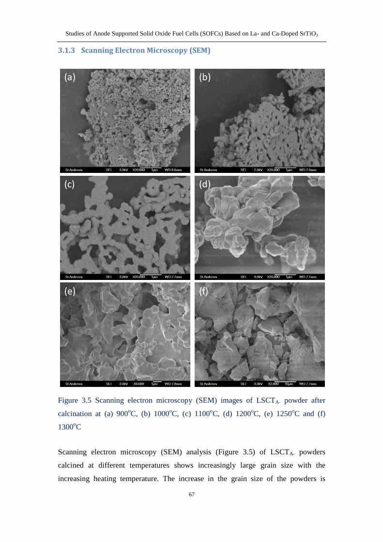
313 Scanning Electron Microscopy (SEM) 67
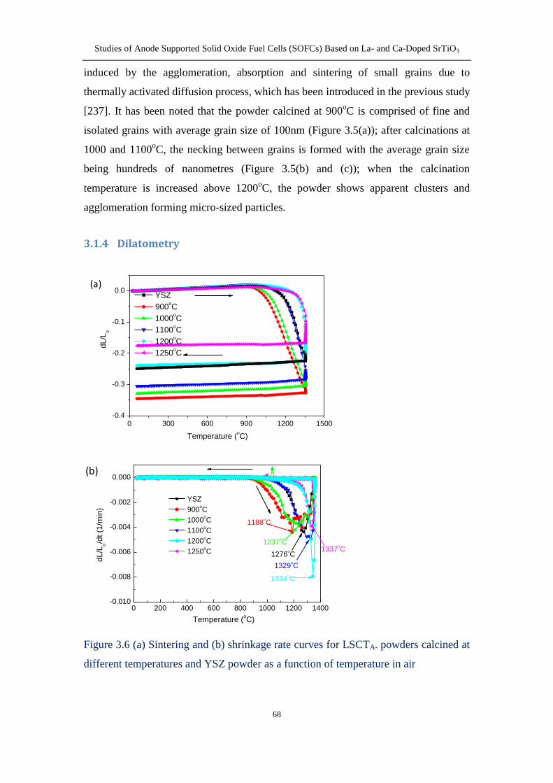
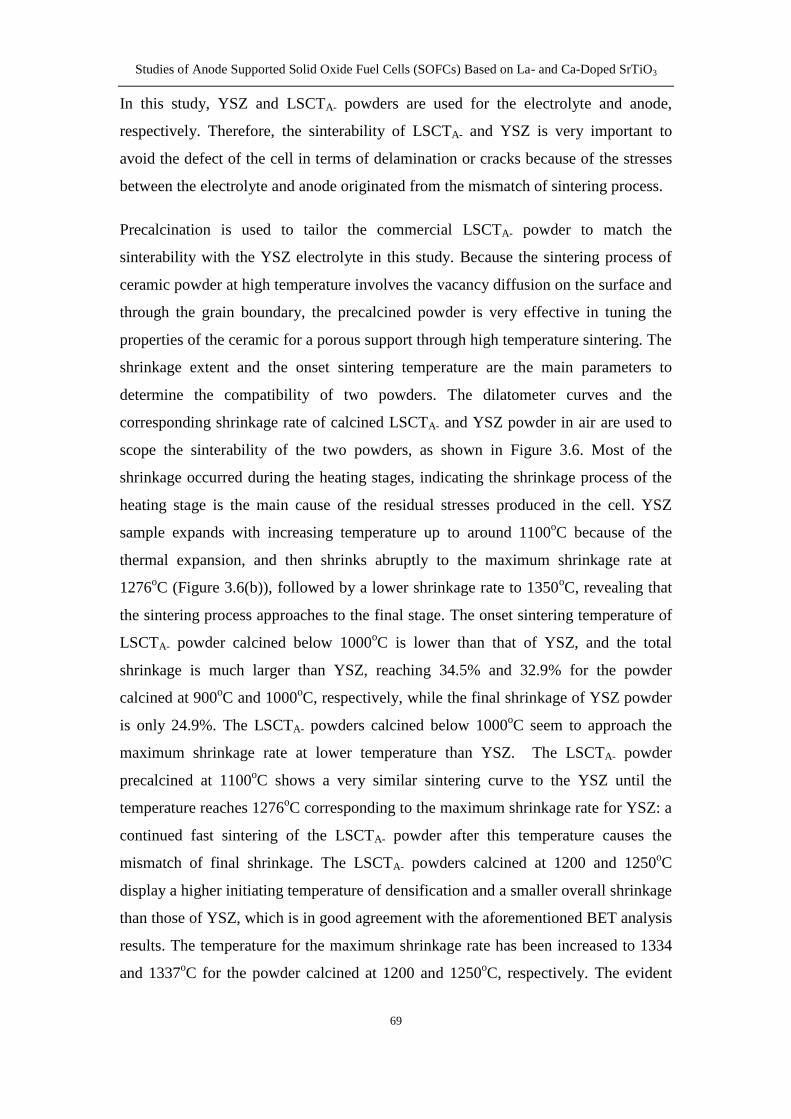
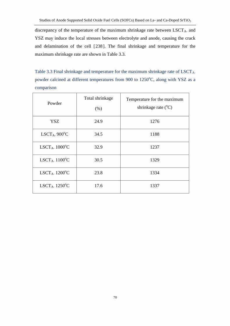
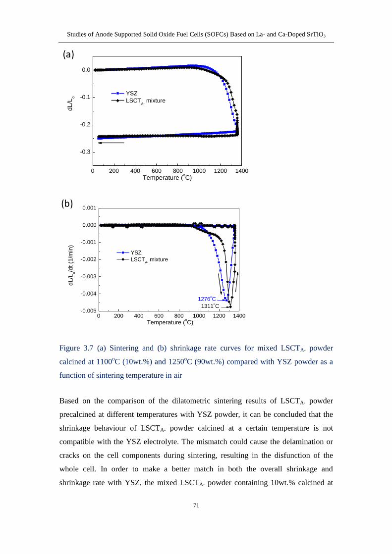
314 Dilatometry 68
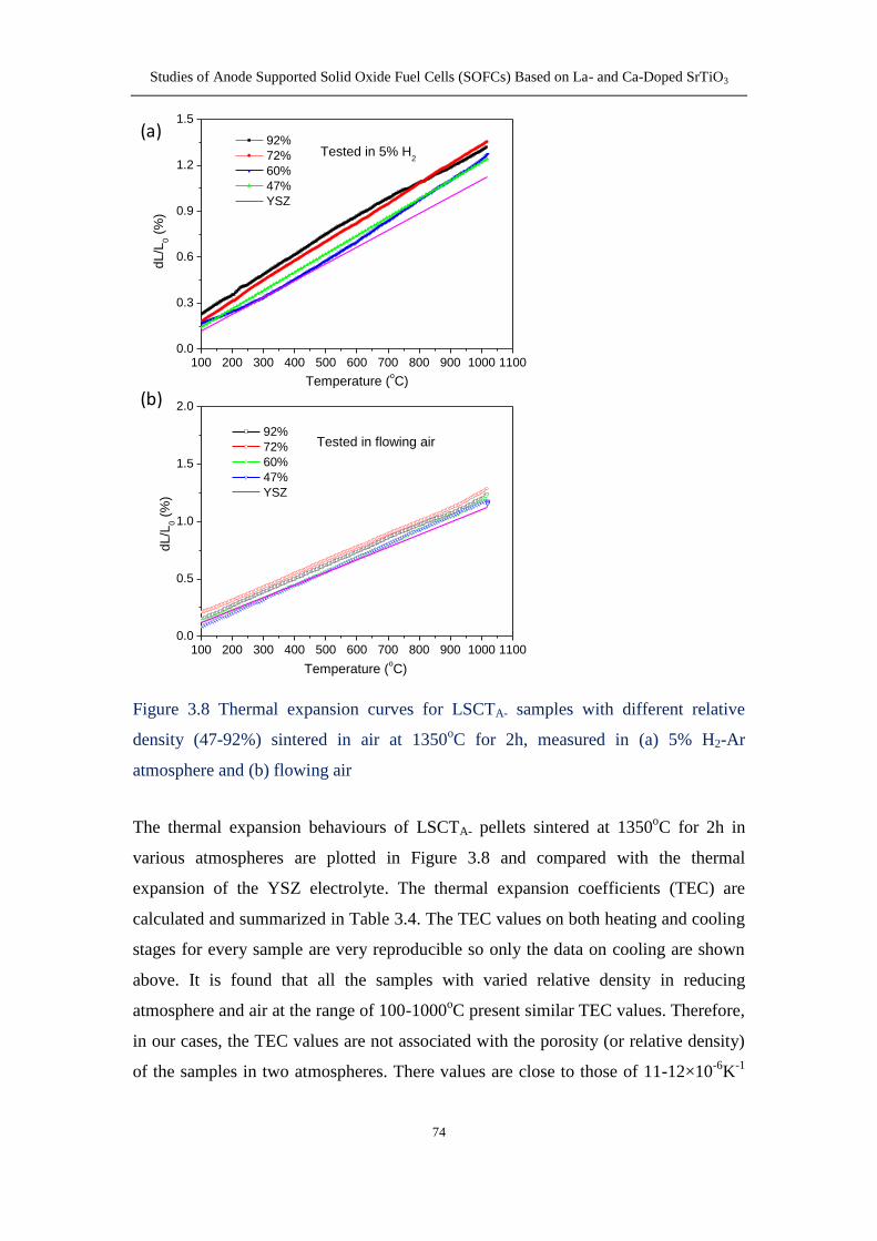
315 Thermal Expansion Coefficient (TEC) 72
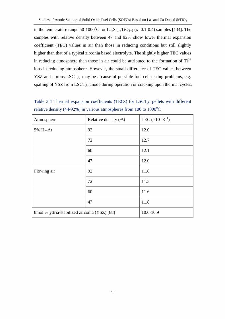
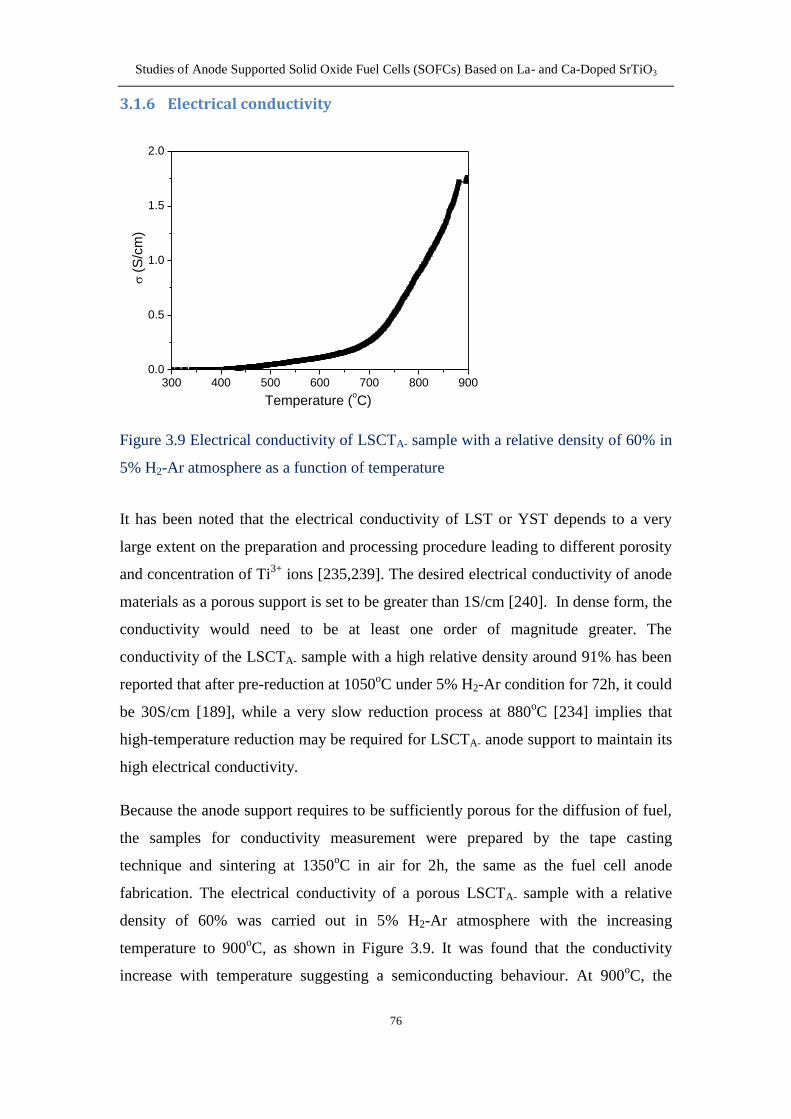
316 Electrical conductivity 76
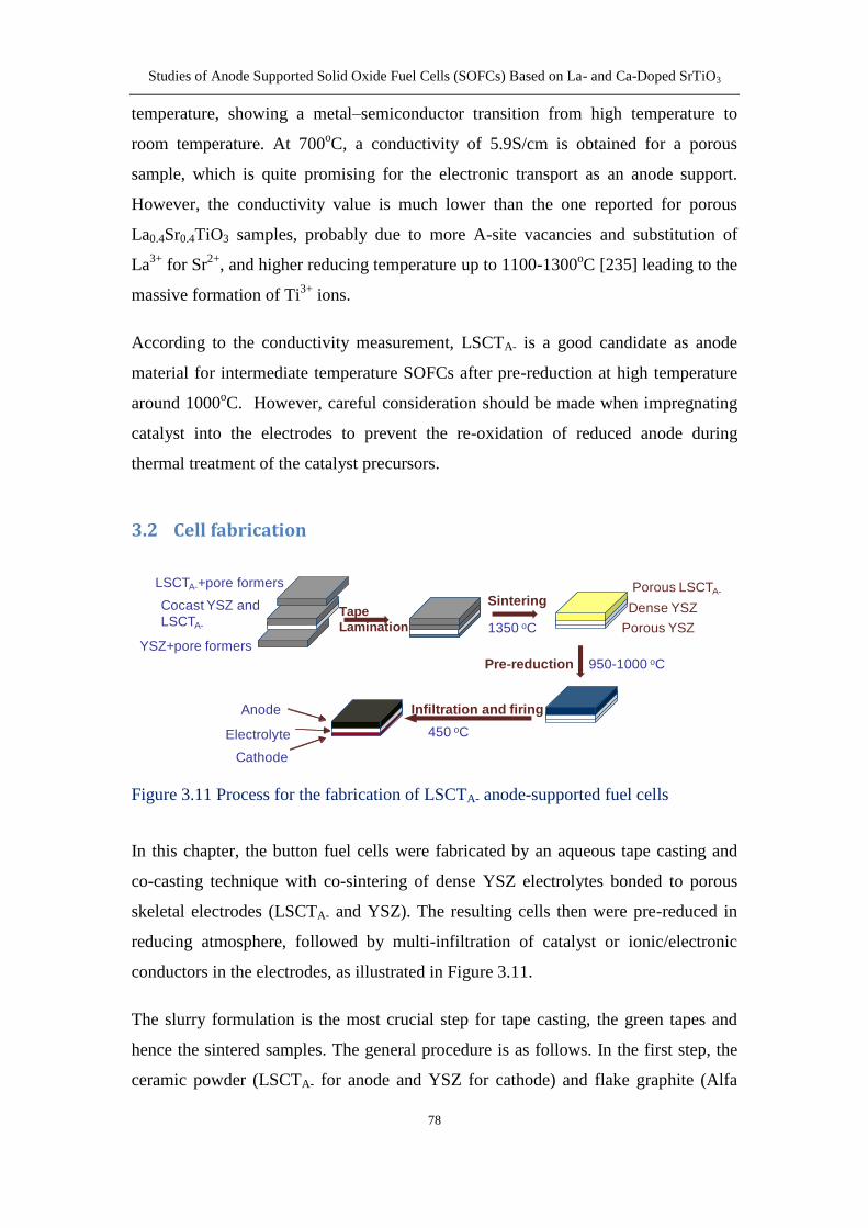
32 Cell fabrication 78
X
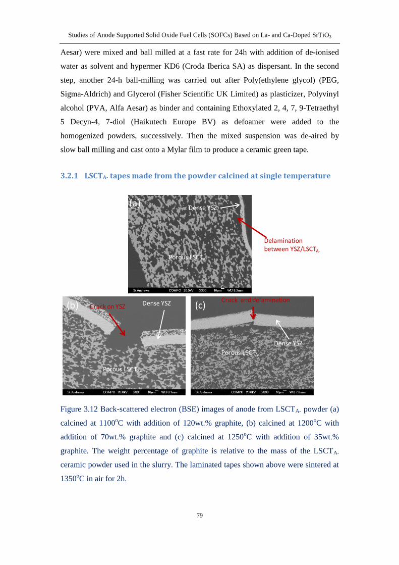
321 LSCTA- tapes made from the powder calcined at single
temperaturehellip 79
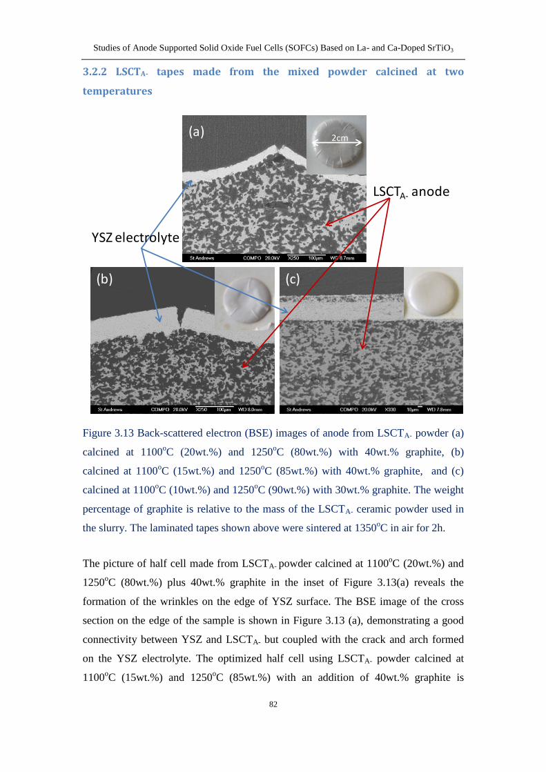
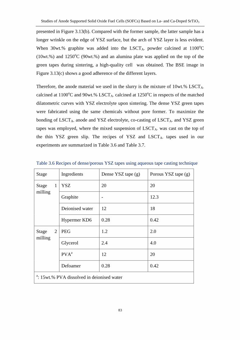
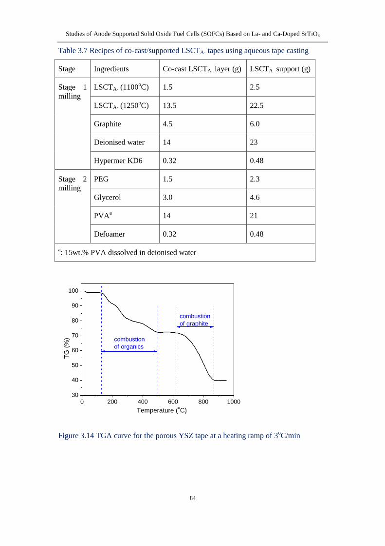
322 LSCTA- tapes made from the mixed powder calcined at two
temperatures 82
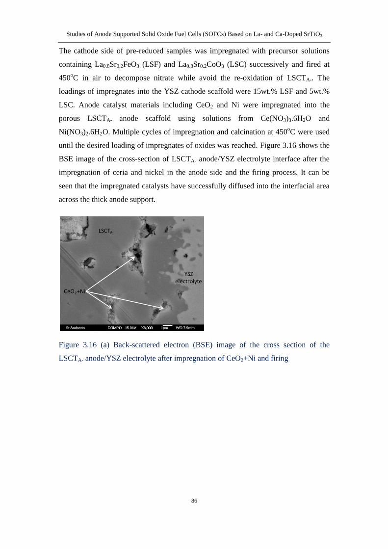
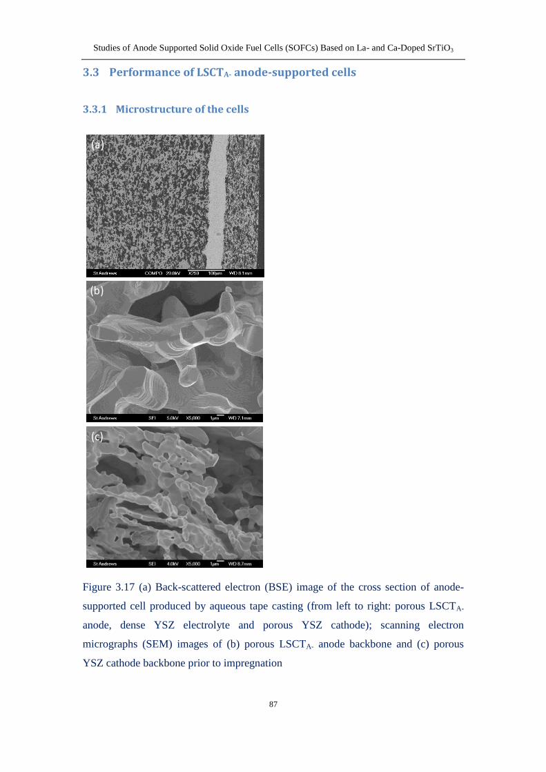
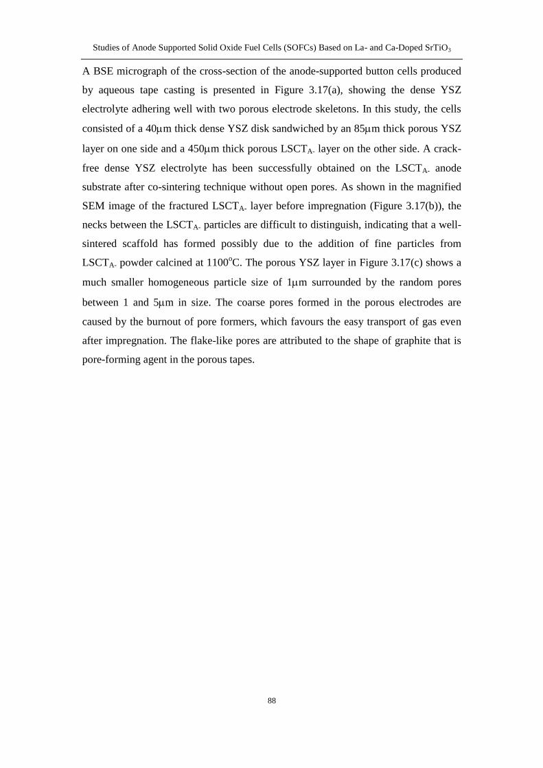
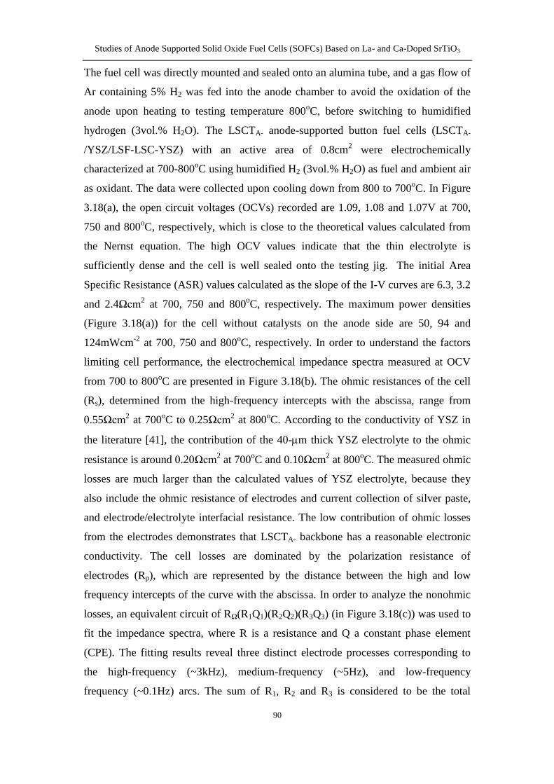
33 Performance of LSCTA- anode-supported cells 87
331 Microstructure of the cells 87
332 Electrochemical testing 89
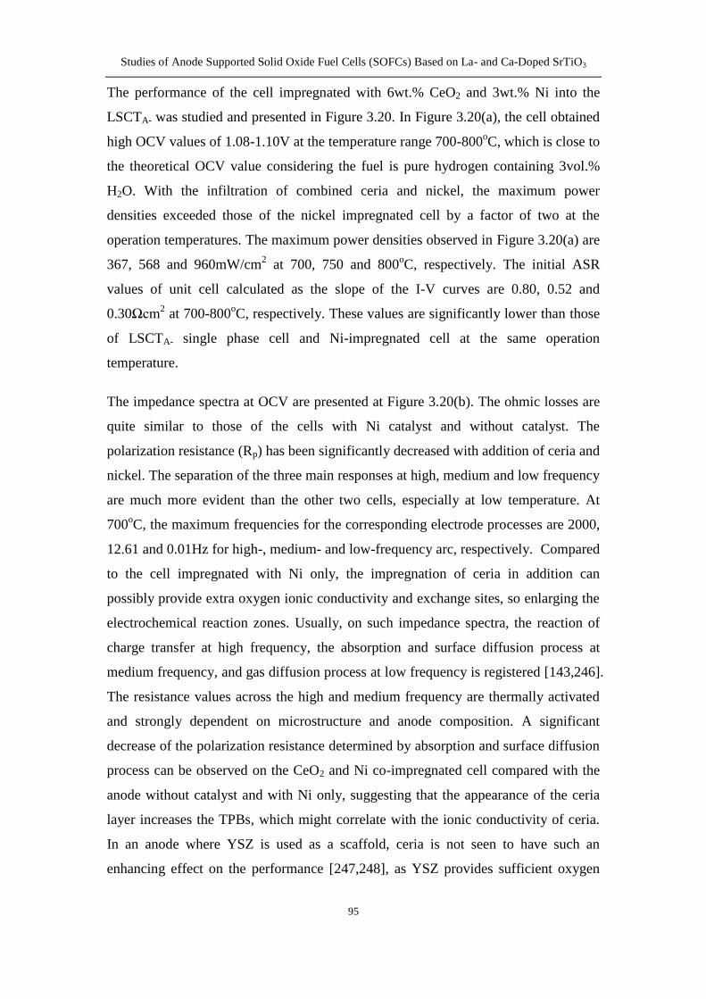
333 Microstructure of impregnated anode 96
34 Conclusion 98
Chapter 4 Stability studies of metal-impregnated LSCTA- anode as support
for SOFCs 99
41 Introduction 99
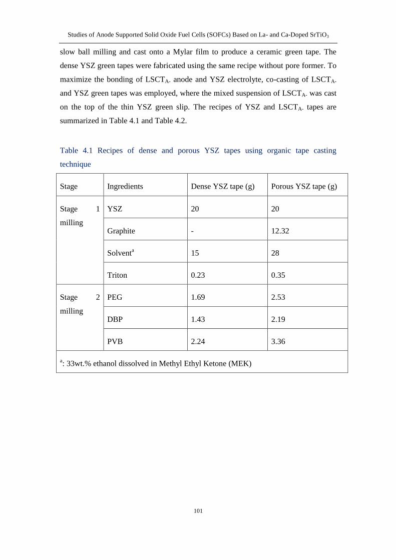
42 Cell fabrication 100
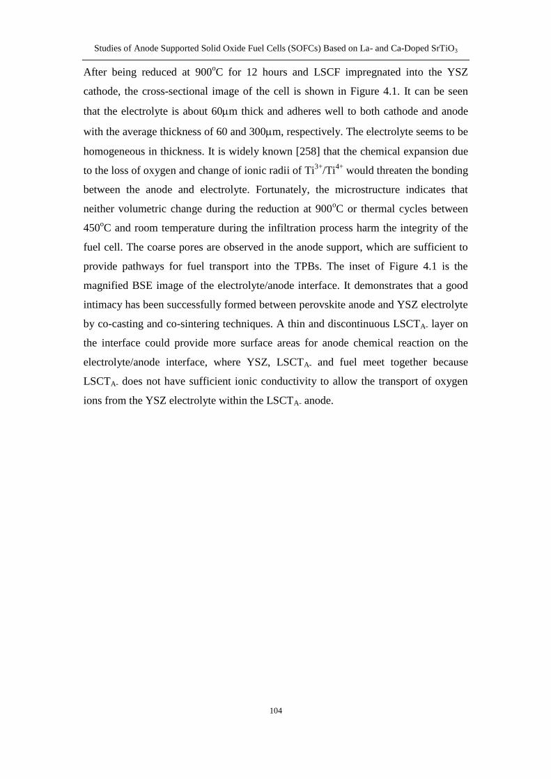
43 Results and discussion 103
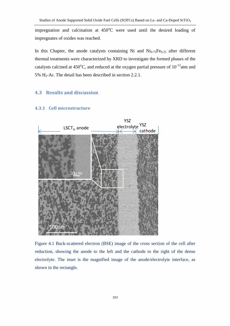
431 Cell microstructure 103
432 EIS of symmetric LSCF-YSZ cell 105
433 Effects of metallic infiltration on the initial performance 106
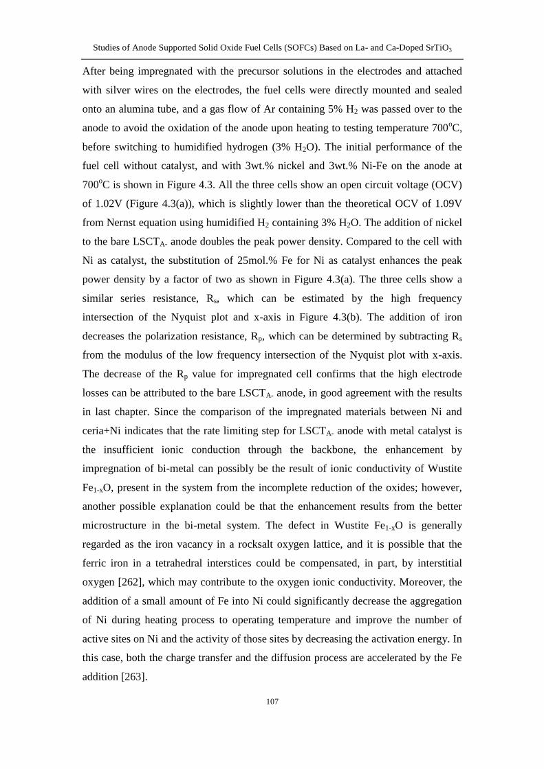
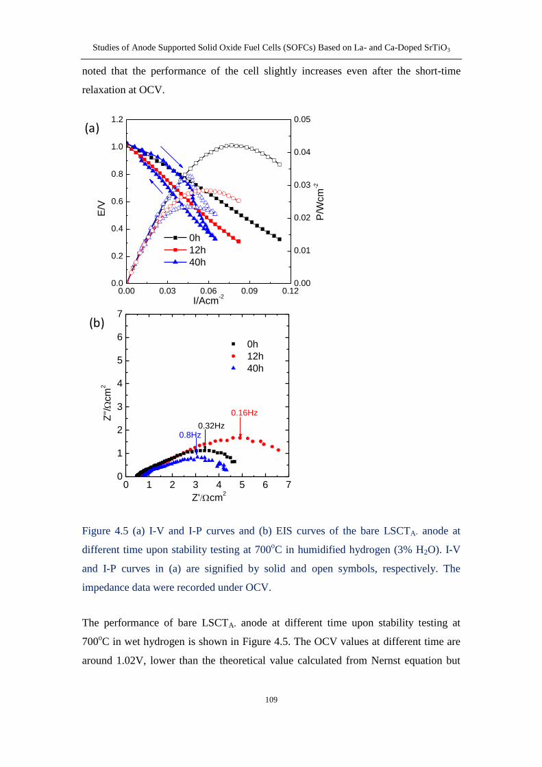
434 Stability of bare LSCTA- anode 108
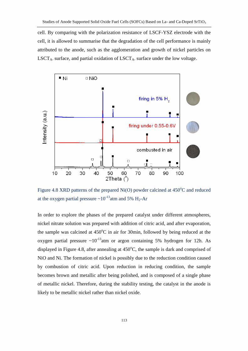
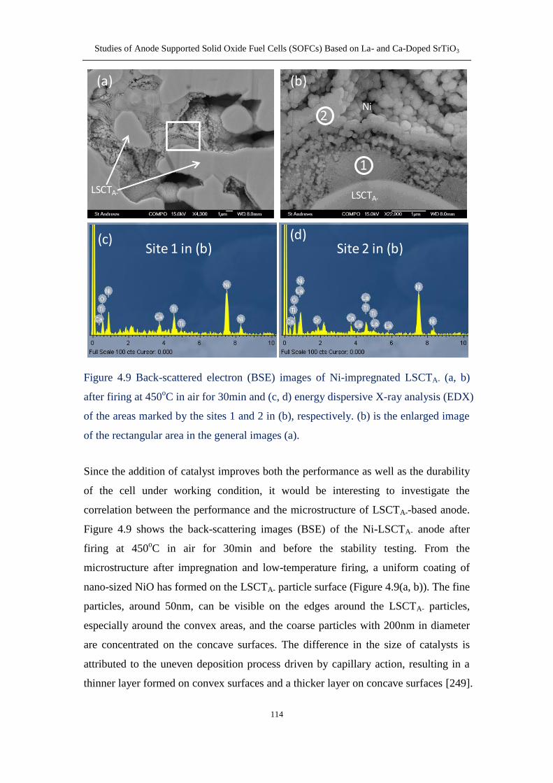
435 Stability of nickel impregnated LSCTA- anode 111
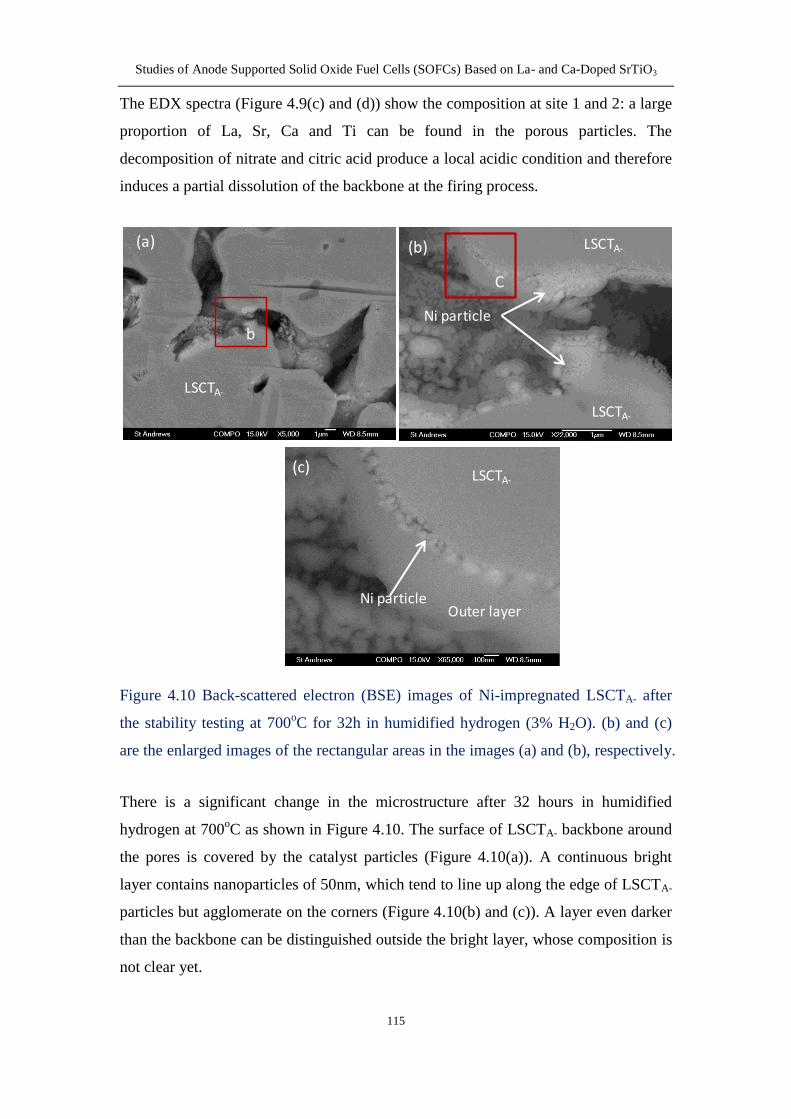
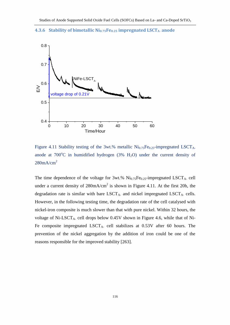
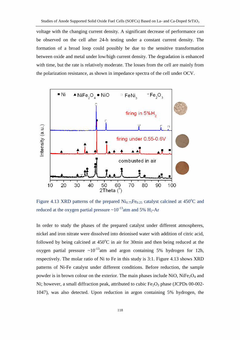
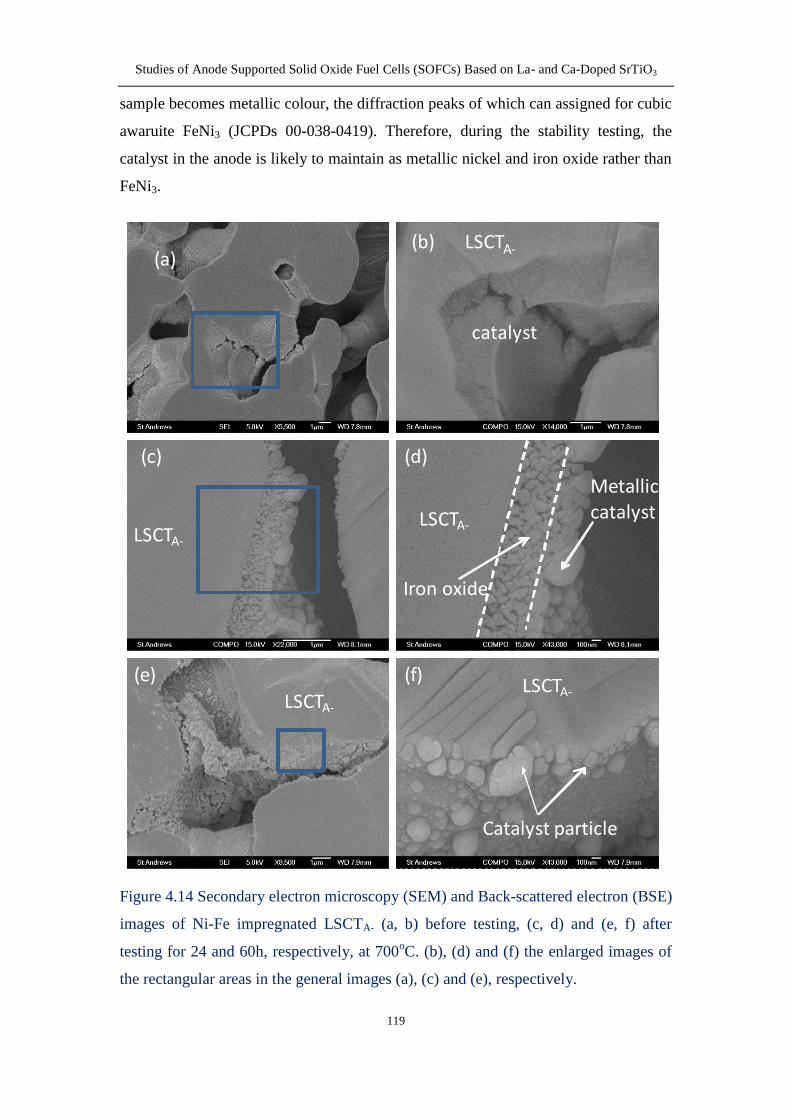
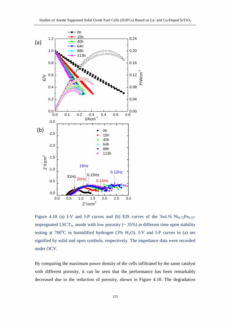
436 Stability of bimetallic Ni075Fe025 impregnated LSCTA- anode 116
437 The effect of anode porosity on the performance of bimetallic
Ni075Fe025 impregnated LSCTA- anode (see section 436) 123
44 Conclusion 126
Chapter 5 Performance of LSCTA- anode infiltrated with CeO2 and metal as
catalyst 128
51 Introduction 128
52 Infiltration 130
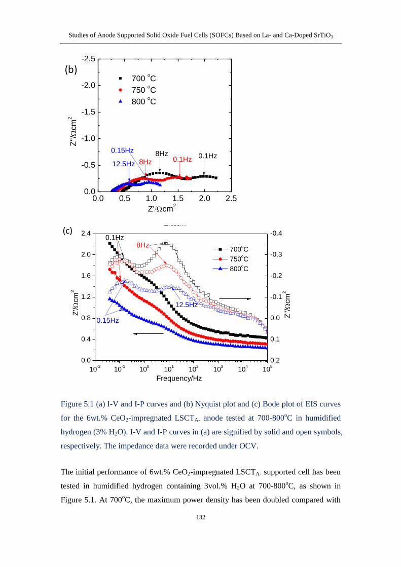
53 Results and discussion 131
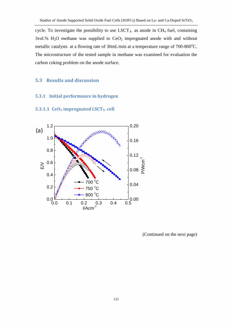
531 Initial performance in hydrogen 131
5311 CeO2 impregnated LSCTA- cell 131
5312 CeO2+Ni impregnated LSCTA- cell 134
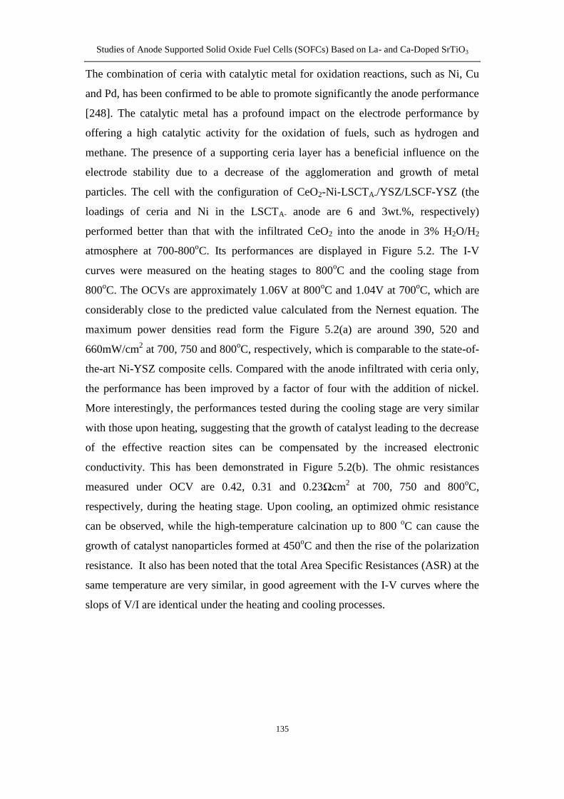
5313 CeO2+Ni075Fe025 impregnated LSCTA- cell 136
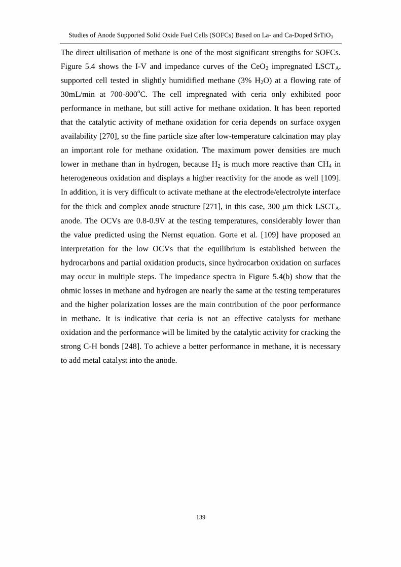
532 Initial performance in methane 138
XI
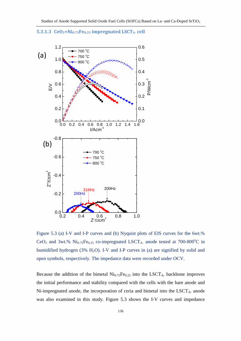
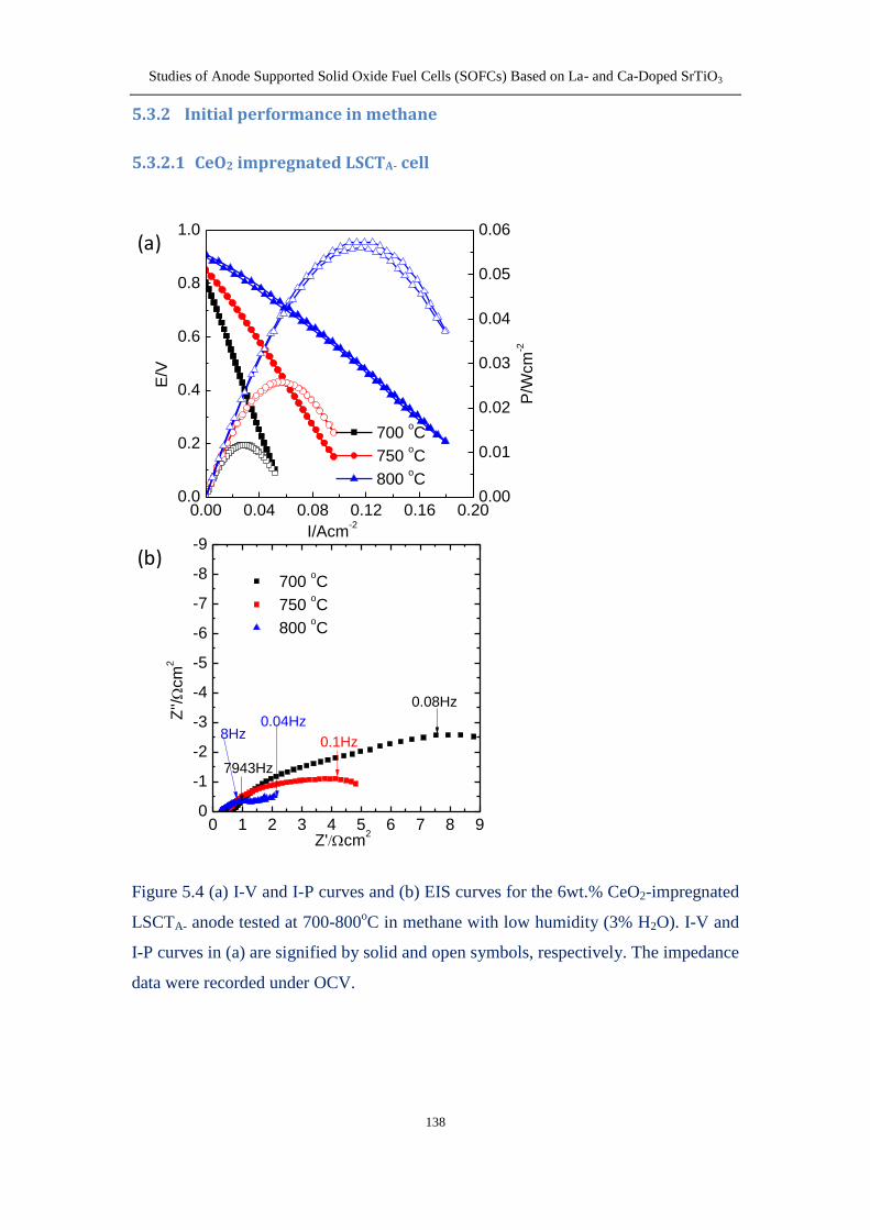
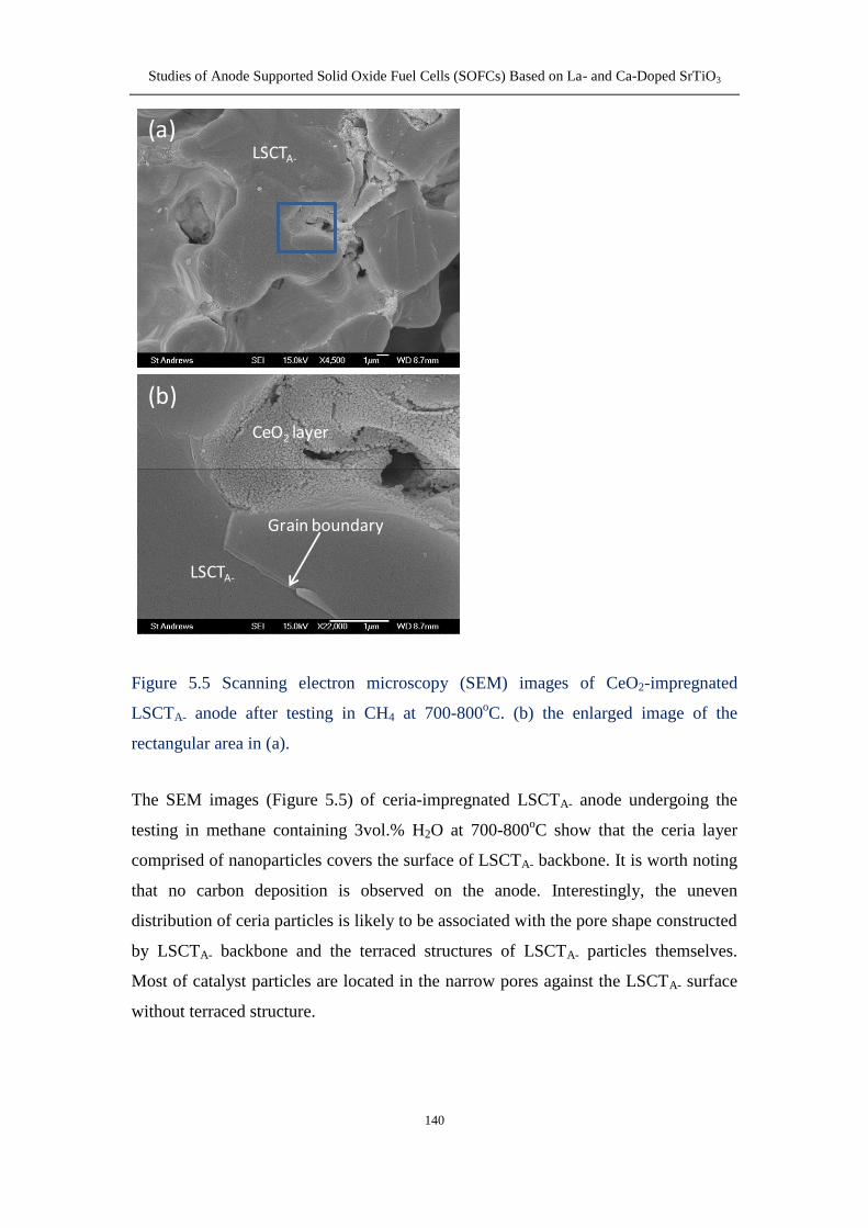
5321 CeO2 impregnated LSCTA- cell 138
5322 CeO2+Ni impregnated LSCTA- cell 141
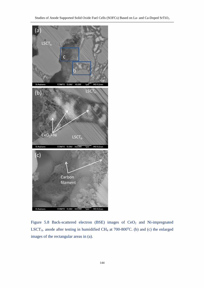
5323 CeO2+Ni075Fe025 impregnated LSCTA- cell 145
533 Stability in hydrogen 148
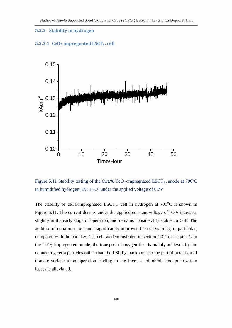
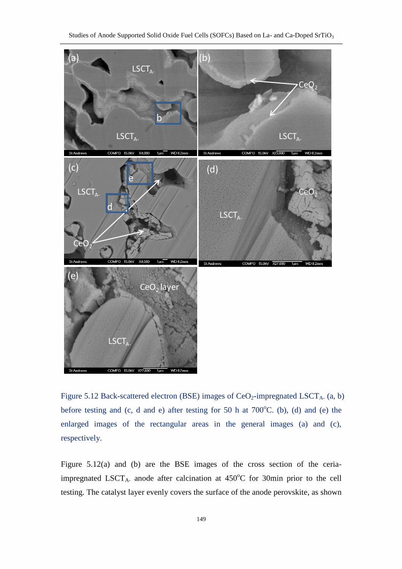
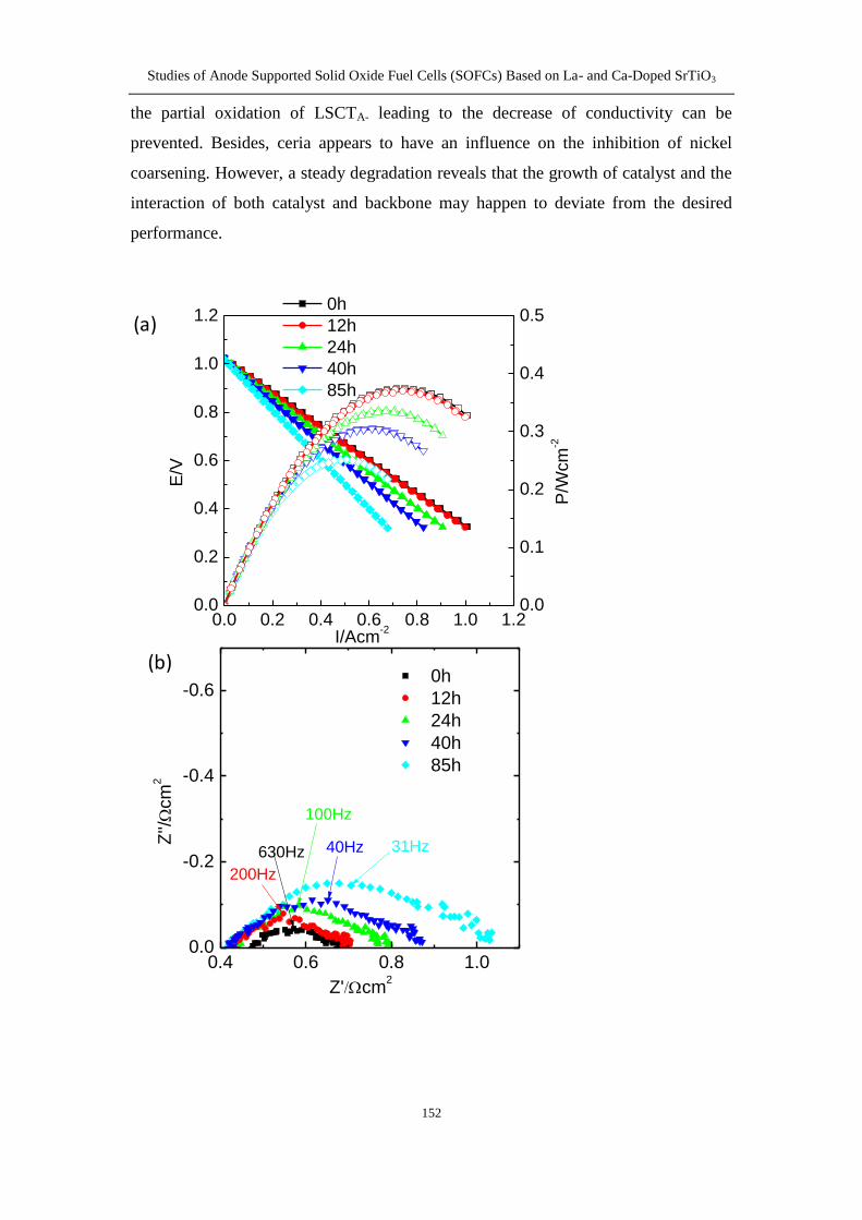
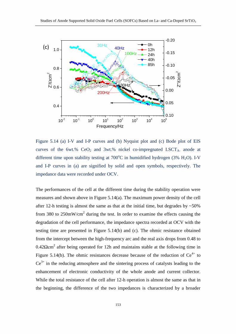
5331 CeO2 impregnated LSCTA- cell 148
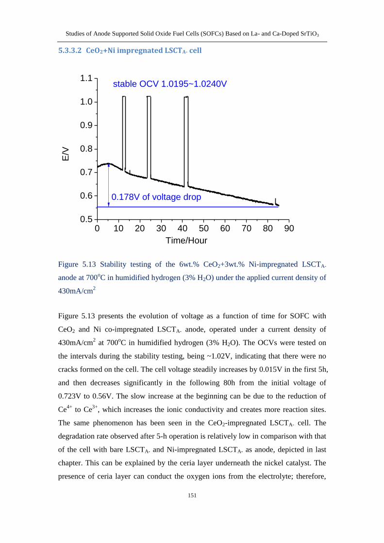
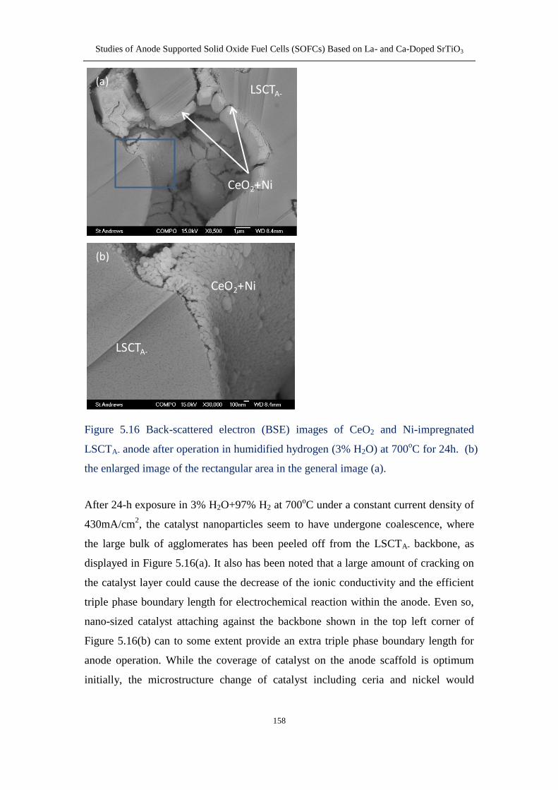
5332 CeO2+Ni impregnated LSCTA- cell 151
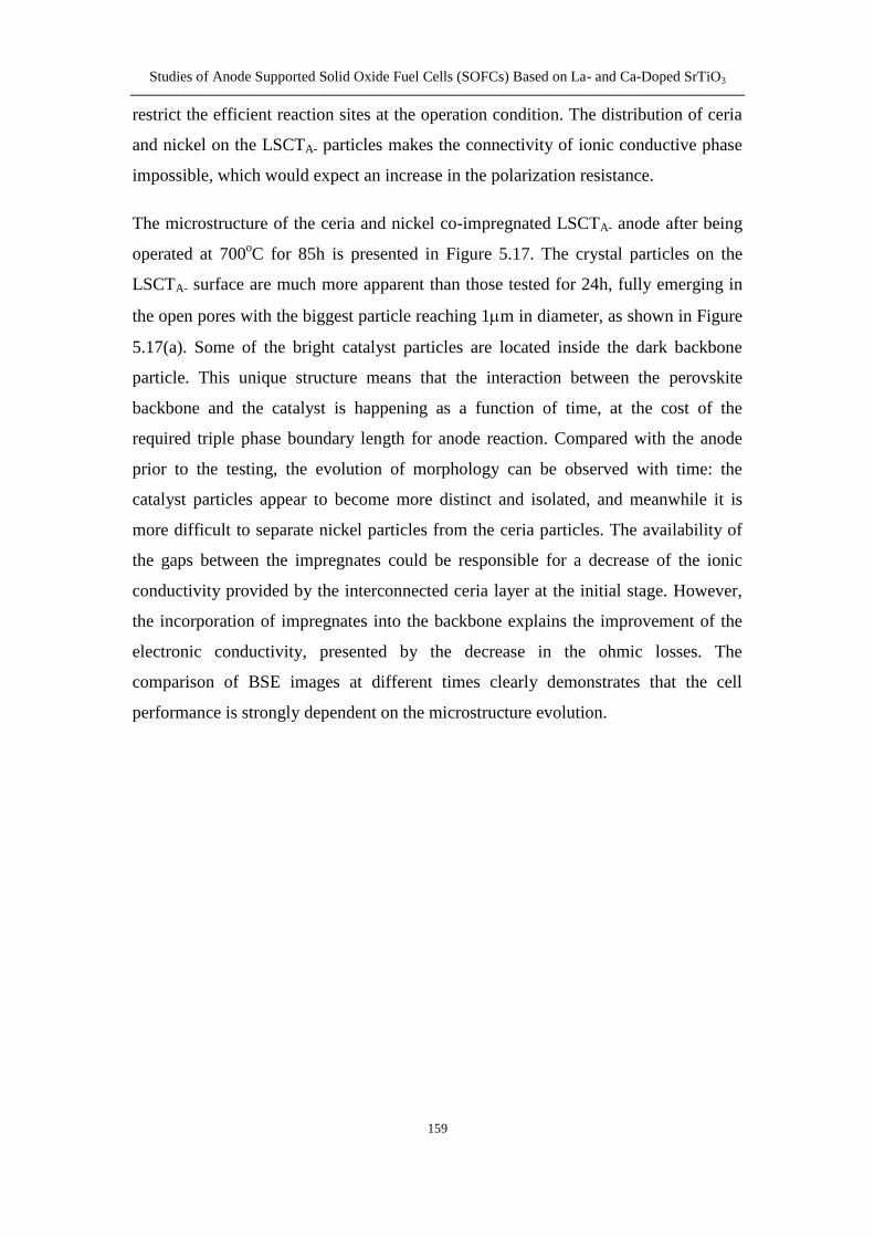
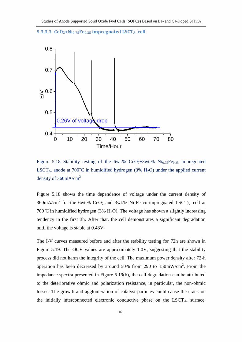
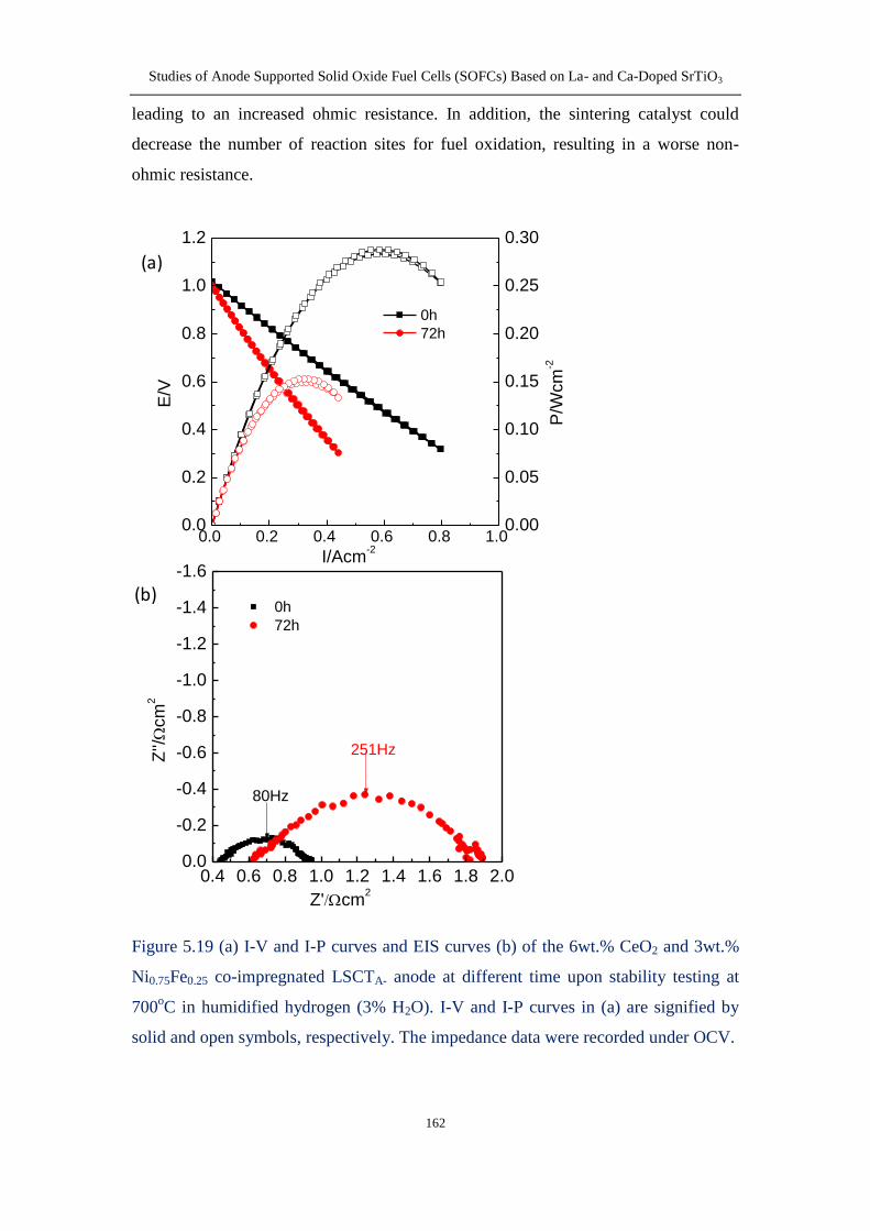
5333 CeO2+Ni075Fe025 impregnated LSCTA- cell 161
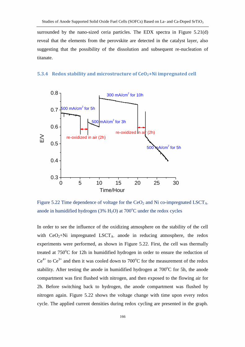
534 Redox stability and microstructure of CeO2+Ni impregnated
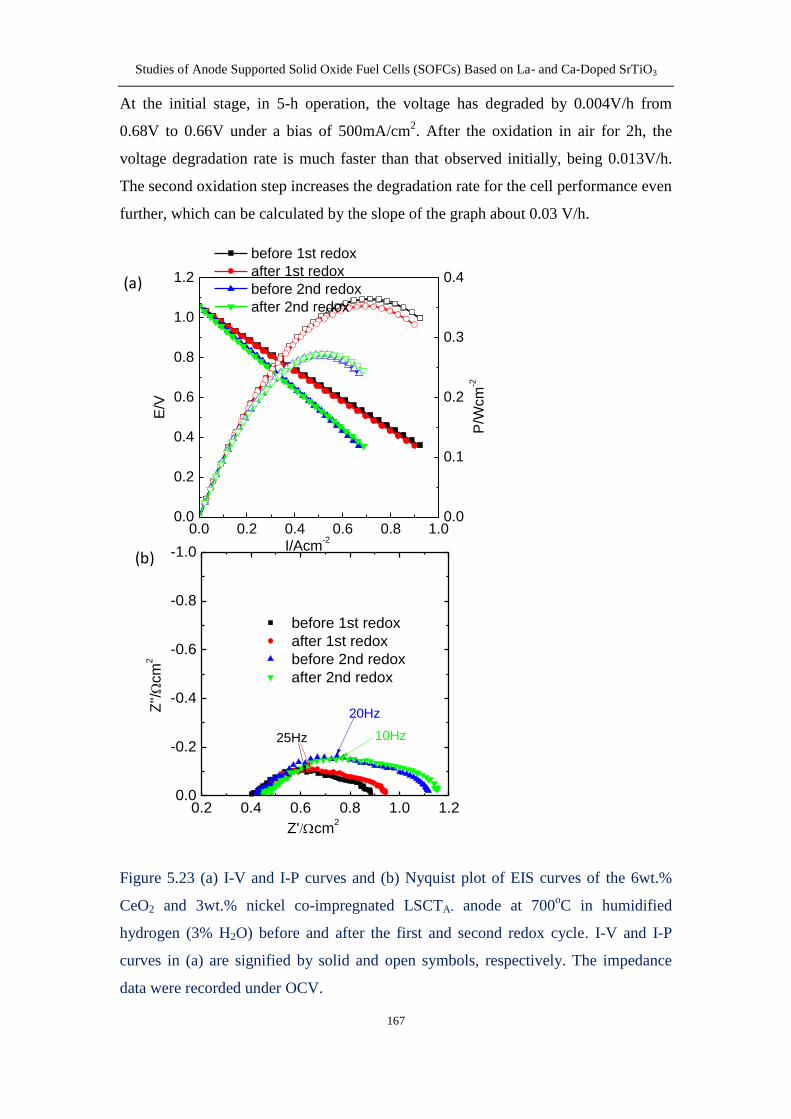
cellhelliphellip 166
54 Conclusion 171
Chapter 6 Effects of YSZLSCTA- ratio and ball-milling process on sintering
processes and electrical properties 172
61 Introduction 172
62 Experimental 173
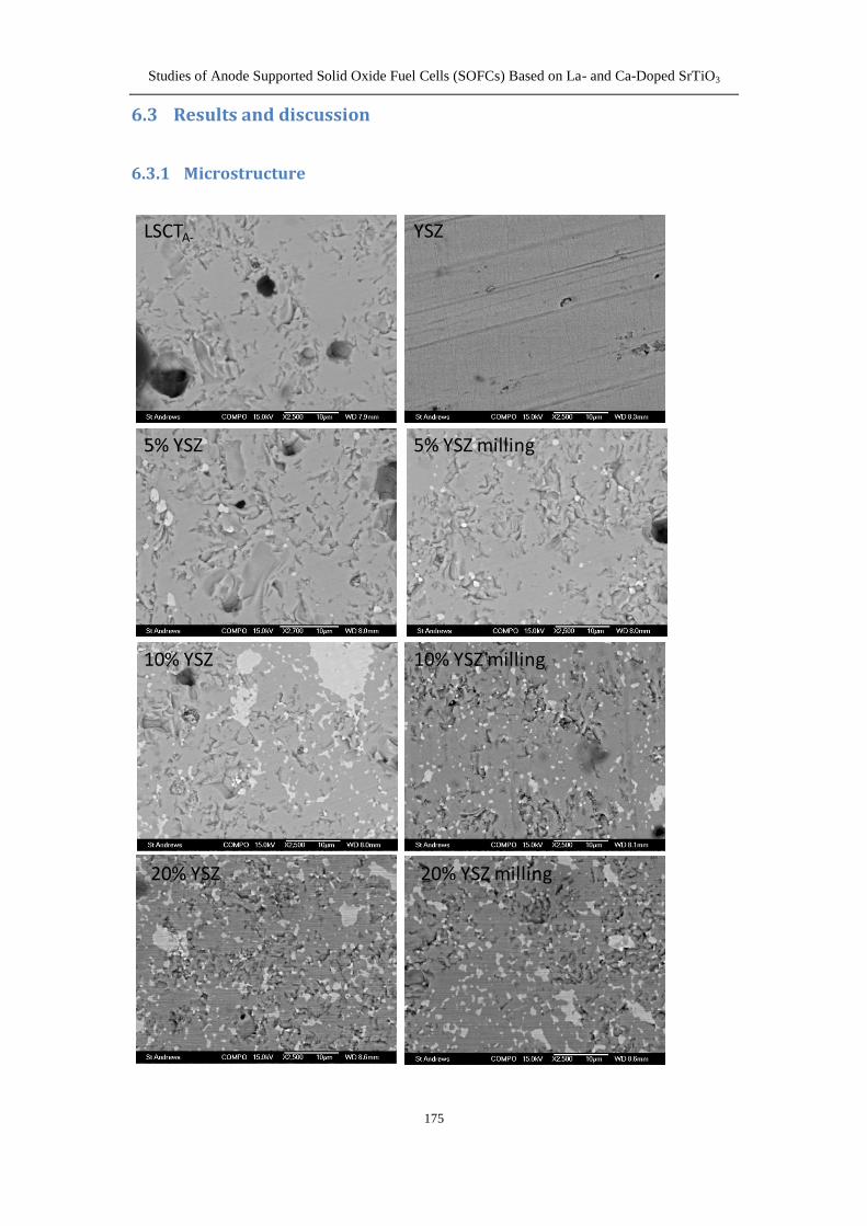
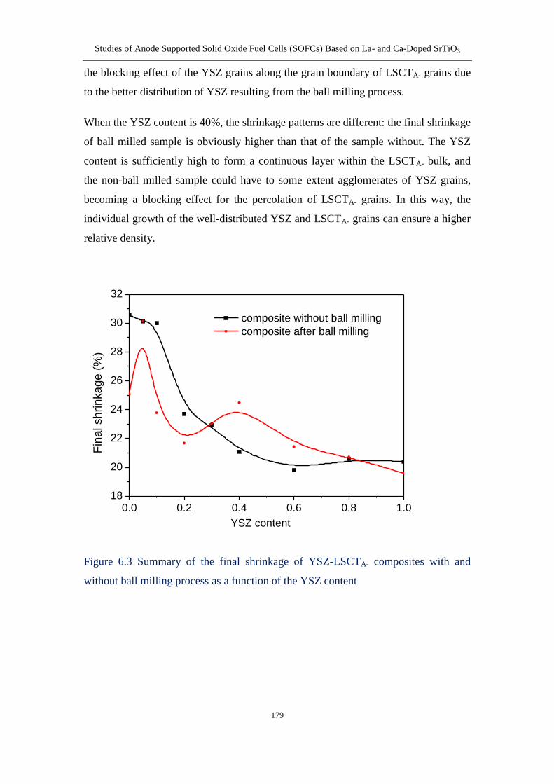
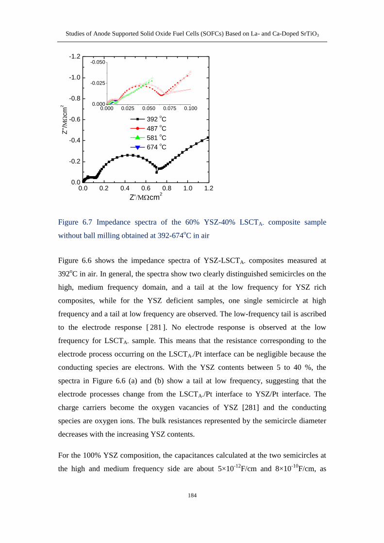
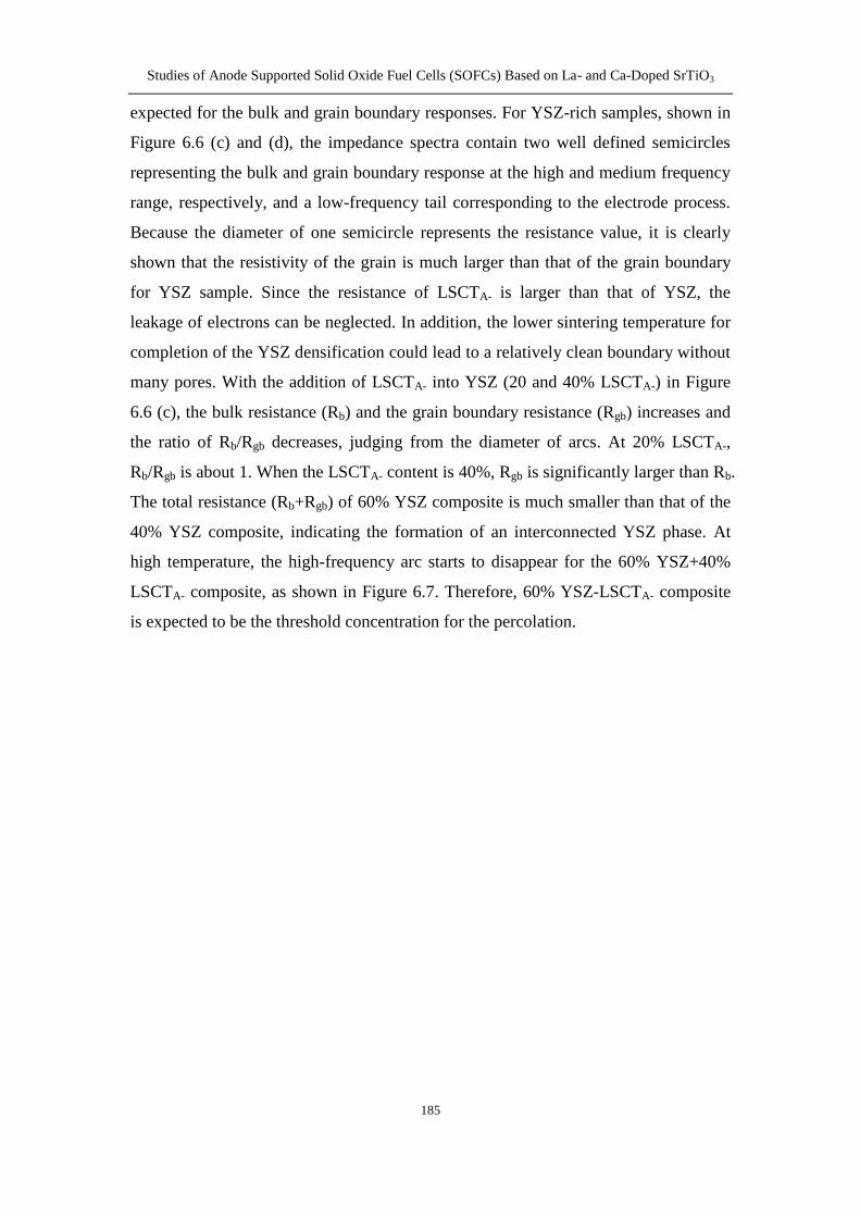
63 Results and discussion 175
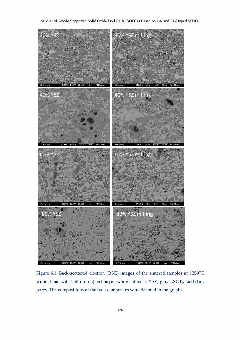
631 Microstructure 175
632 Dilatometry 178
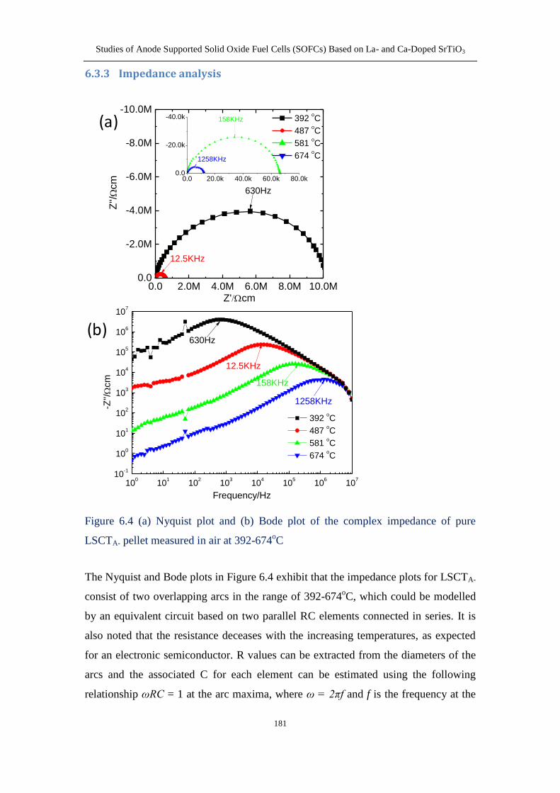
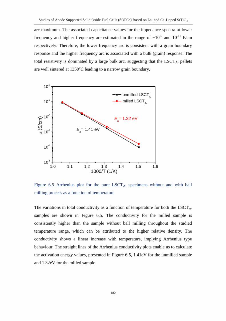
633 Impedance analysis 181
64 Conclusion 187
Chapter 7 Ni-YSZ coating prepared by electroless co-deposition process for
an SOFC anode 189
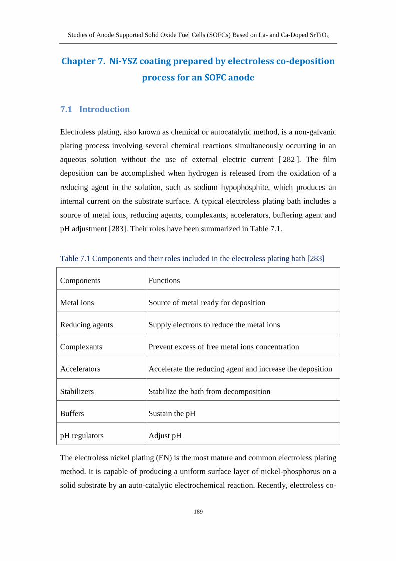
71 Introduction 189
72 Experimental 191
721 Preparation of the half cells 191
722 Ni-YSZ co-deposition onto half cells 192
723 Characterization of Ni-YSZ coatings 193
724 Cell performance testing 193
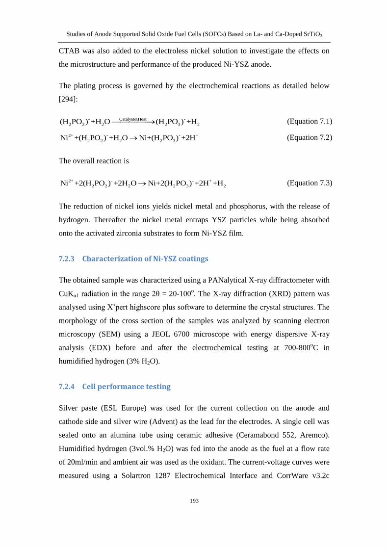
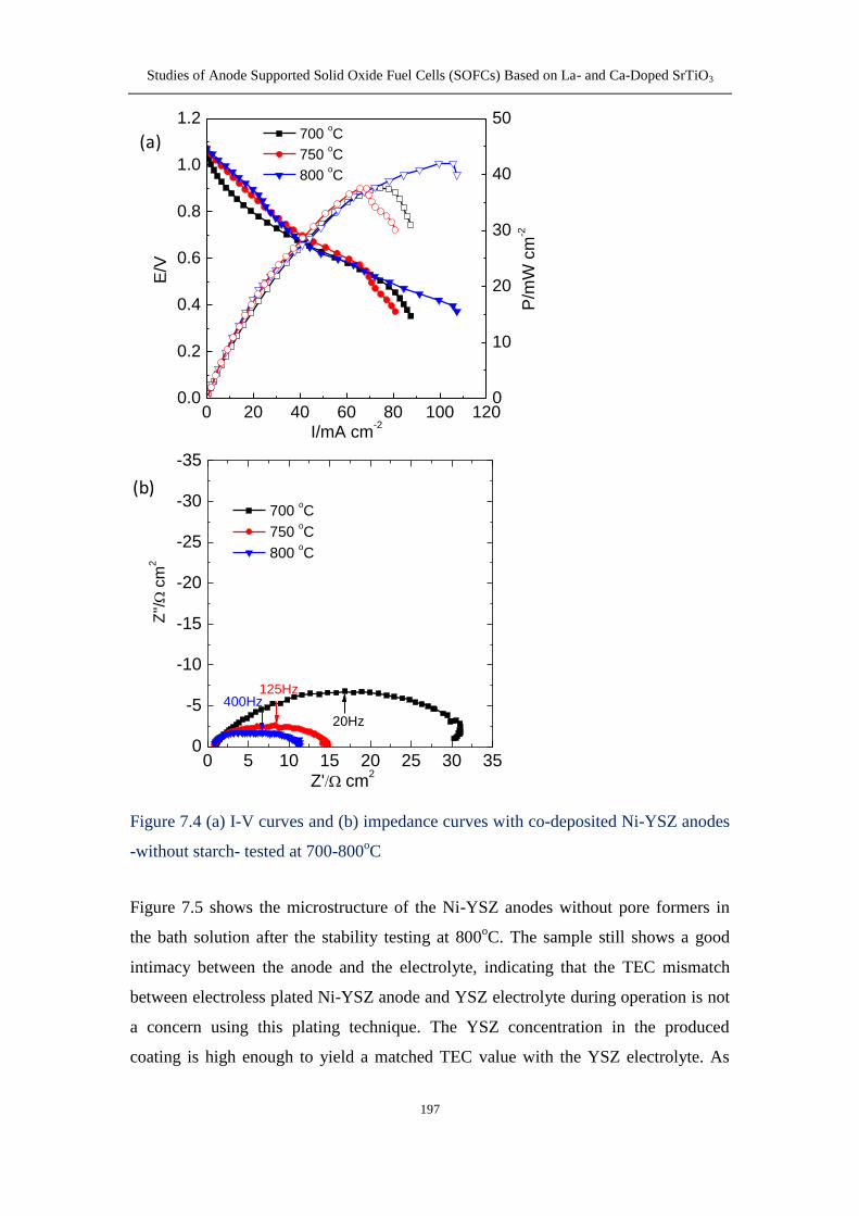
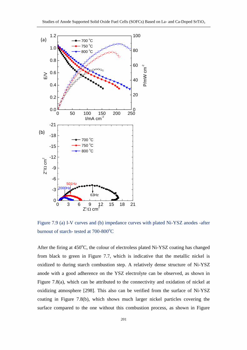
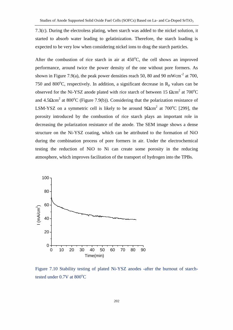
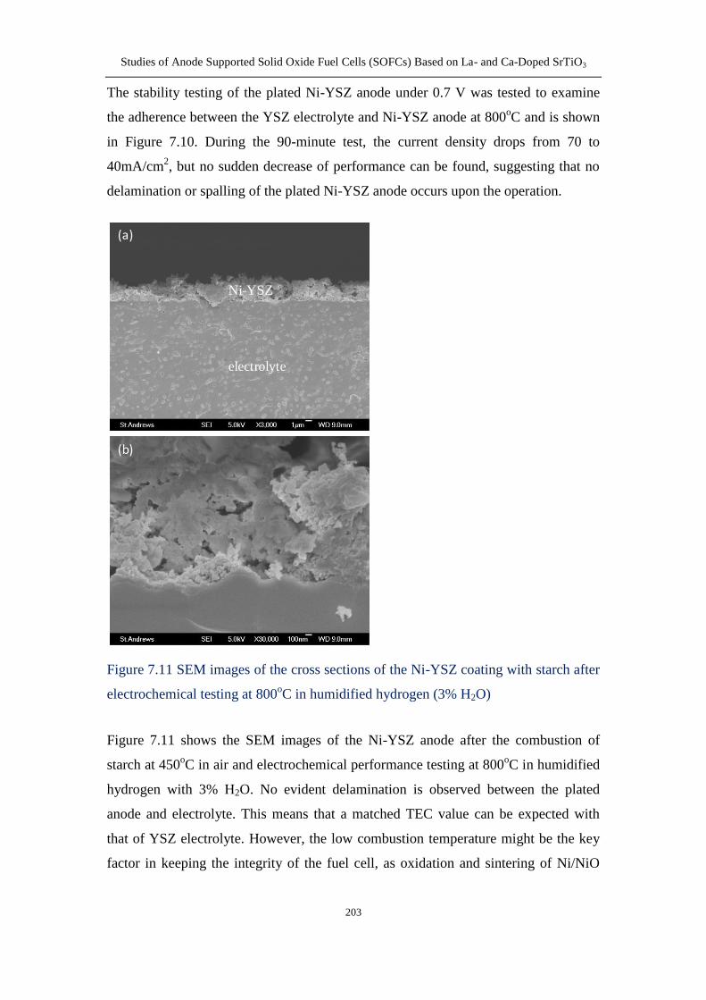
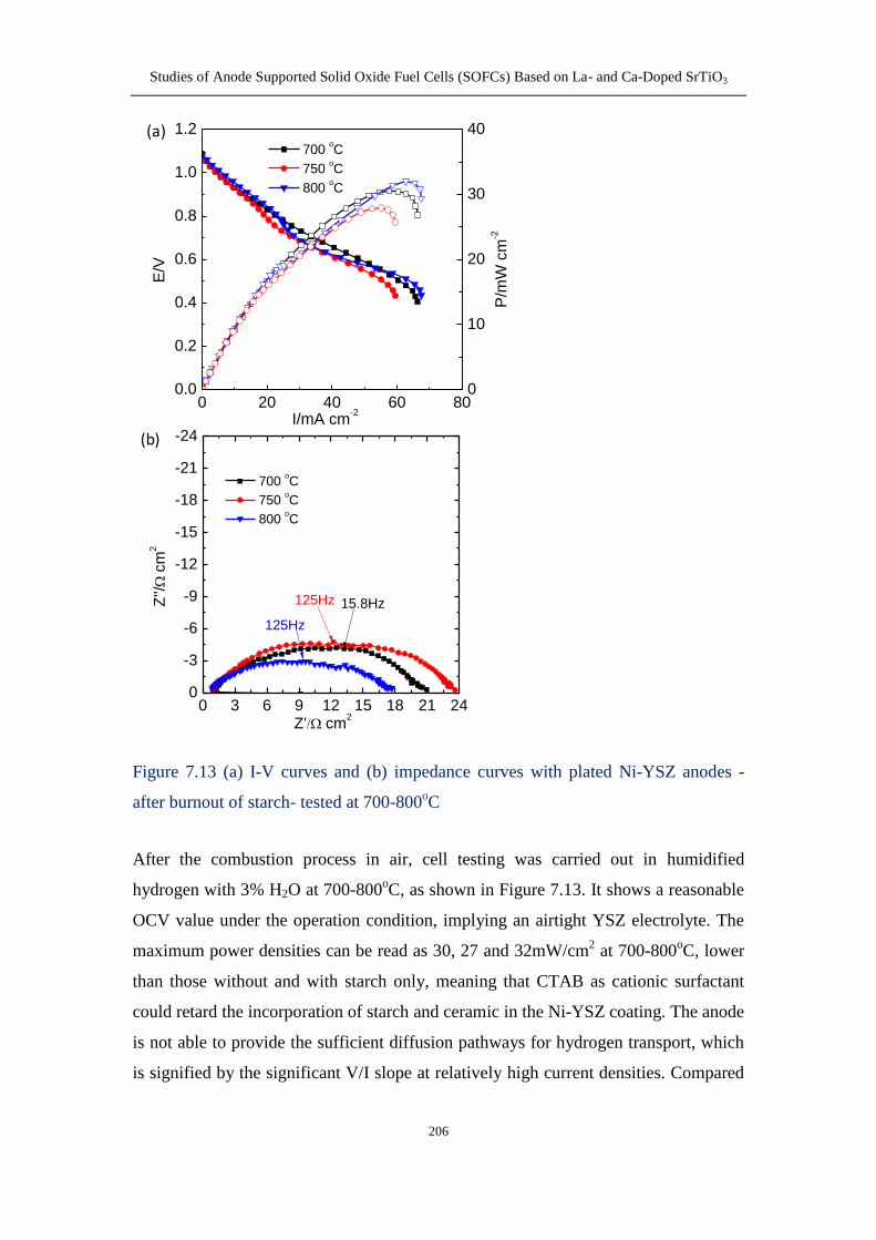
73 Results and discussion 194
731 XRD pattern 194
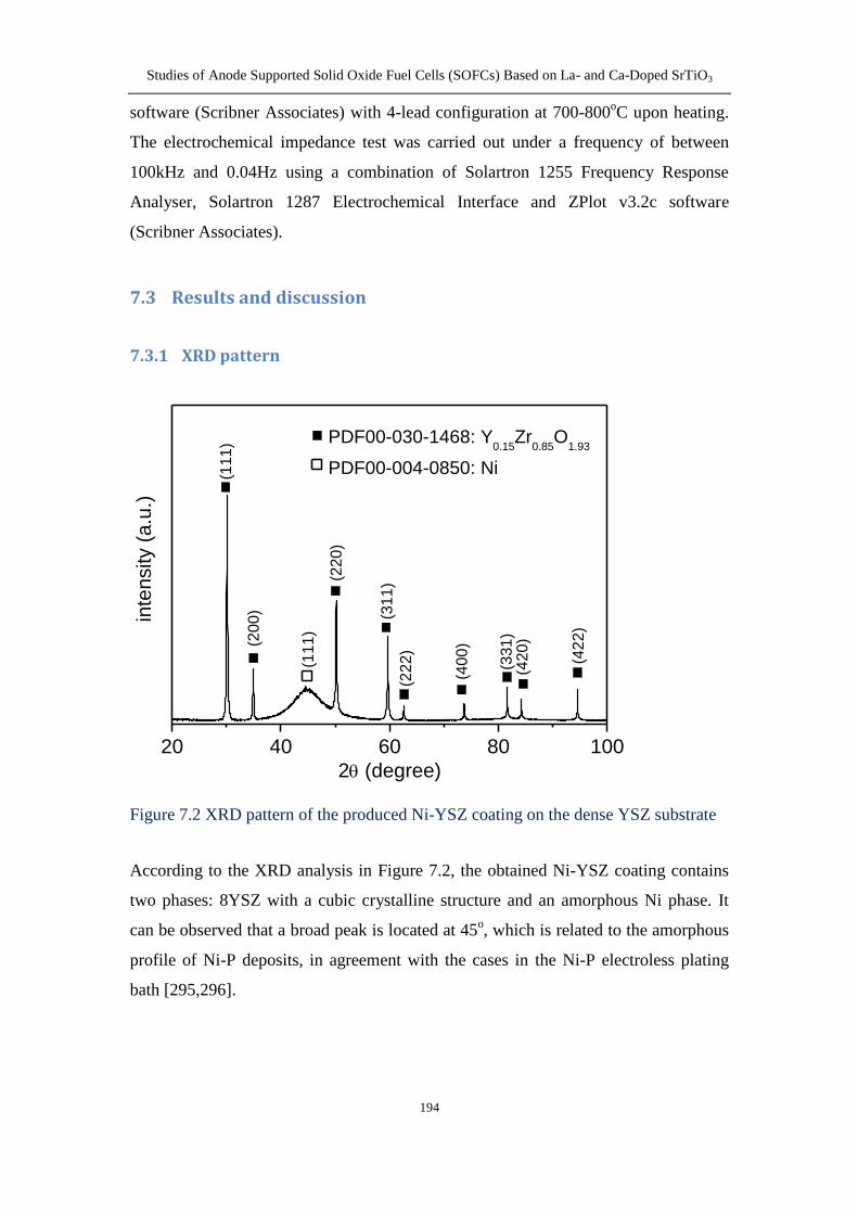
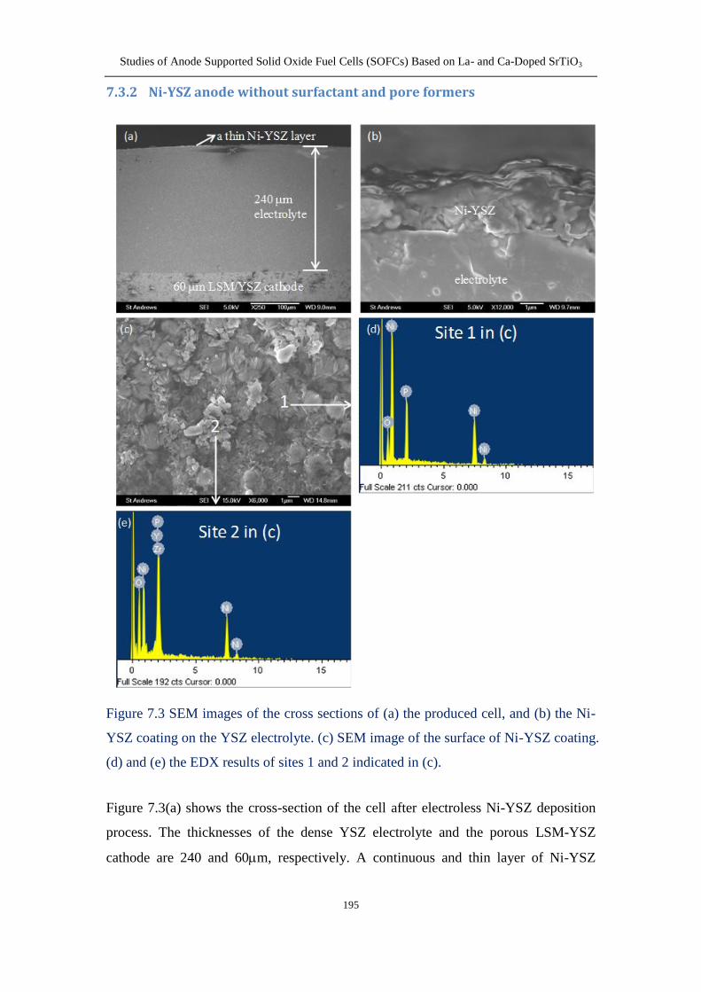
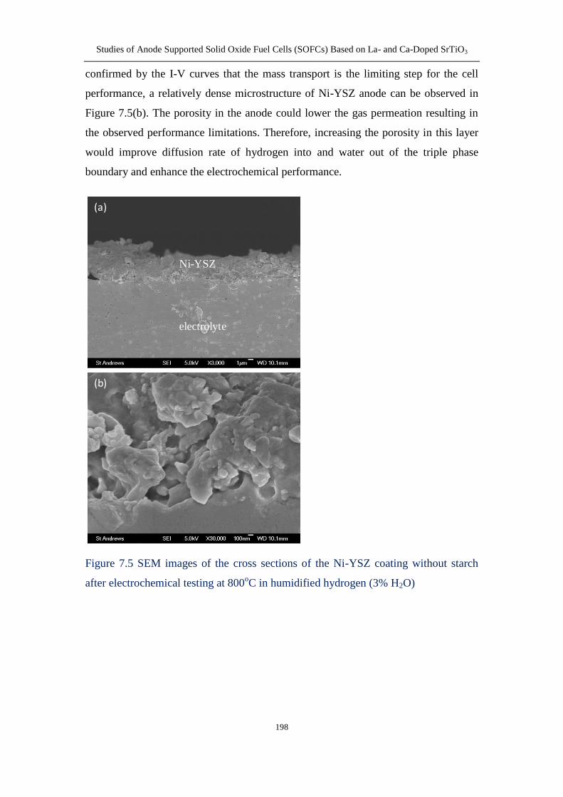
732 Ni-YSZ anode without surfactant and pore formers 195
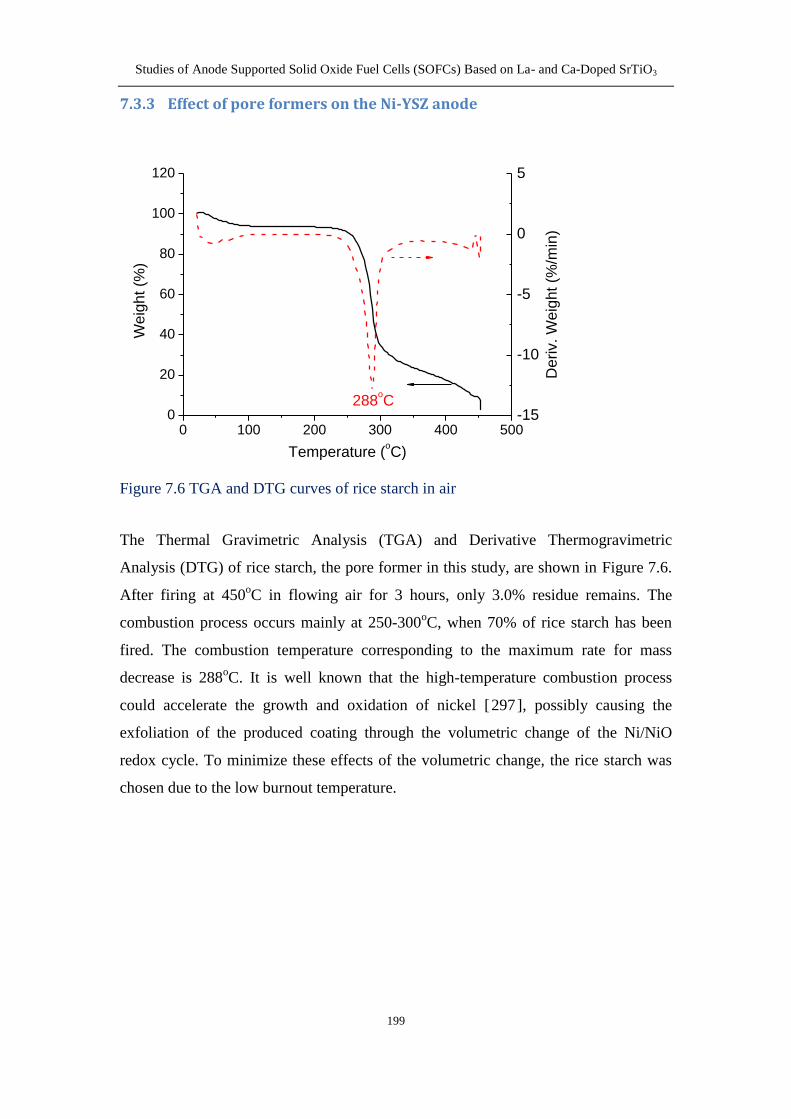
733 Effect of pore formers on the Ni-YSZ anode 199
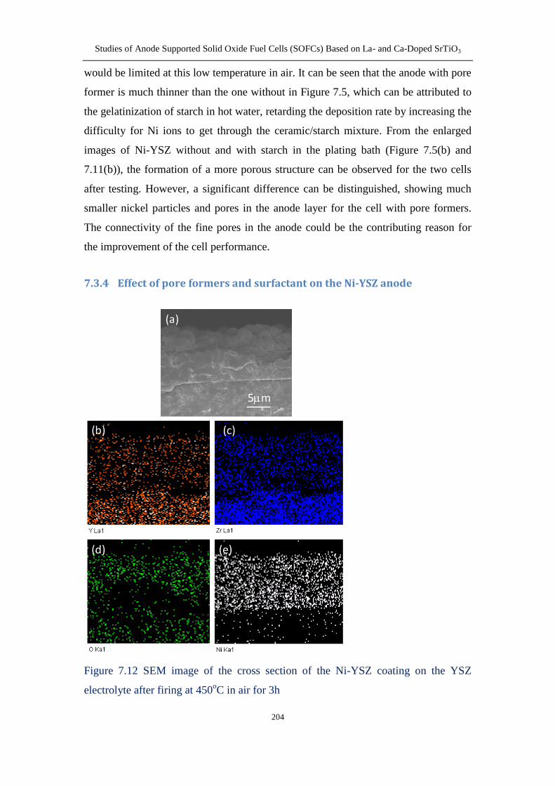
734 Effect of pore formers and surfactant on the Ni-YSZ anode 204
74 Conclusion 207
XII
General conclusions 208
Suggestions for future work 208
References 212
Studies of Anode Supported Solid Oxide Fuel Cells (SOFCs) Based on La- and Ca-Doped SrTiO3
1
Chapter 1 Introduction
11 Fuel cell technology
111 Definition
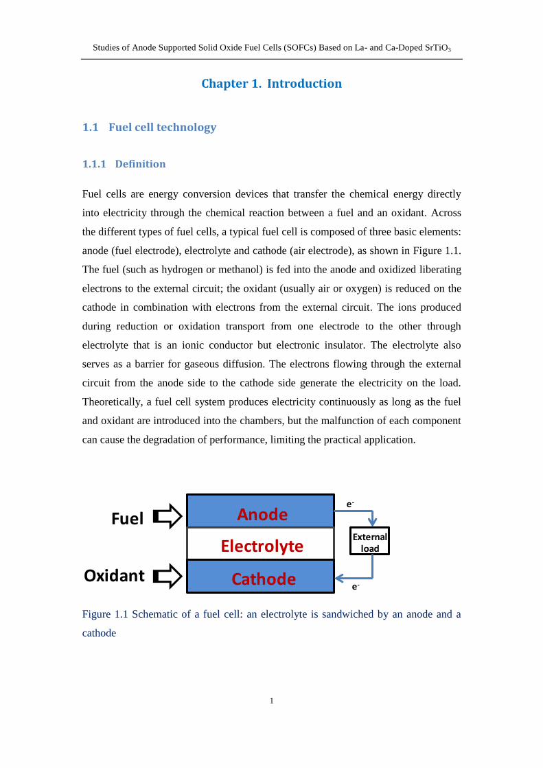
Fuel cells are energy conversion devices that transfer the chemical energy directly
into electricity through the chemical reaction between a fuel and an oxidant Across
the different types of fuel cells a typical fuel cell is composed of three basic elements
anode (fuel electrode) electrolyte and cathode (air electrode) as shown in Figure 11
The fuel (such as hydrogen or methanol) is fed into the anode and oxidized liberating
electrons to the external circuit the oxidant (usually air or oxygen) is reduced on the
cathode in combination with electrons from the external circuit The ions produced
during reduction or oxidation transport from one electrode to the other through
electrolyte that is an ionic conductor but electronic insulator The electrolyte also
serves as a barrier for gaseous diffusion The electrons flowing through the external
circuit from the anode side to the cathode side generate the electricity on the load
Theoretically a fuel cell system produces electricity continuously as long as the fuel
and oxidant are introduced into the chambers but the malfunction of each component
can cause the degradation of performance limiting the practical application
Figure 11 Schematic of a fuel cell an electrolyte is sandwiched by an anode and a
cathode
Anode
Electrolyte
Cathode
Fuel
Oxidant
External load
e-
e-
Studies of Anode Supported Solid Oxide Fuel Cells (SOFCs) Based on La- and Ca-Doped SrTiO3
2
112 History
The concept of fuel cells has been efficiently demonstrated by Humphry Davy dating
from the early nineteenth century [1] The first hydrogen fuel cell was successfully
invented by William Grove in 1839 [2] generally referred as the start of fuel cell
history He discovered a small amount of current flowing between the two platinum
electrodes immersed into the sulphuric acid as a result of the chemical reaction of
hydrogen and oxygen produced from electrolysis reaction of water [3]
Until the early 20th
century much effort had been devoted to the optimization of the
original fuel cells However the development of fuel cell technology has been limited
by the electrode materials and manufacturing methods In 1959 Francis Bacon
successfully prepared a 5KW stationary fuel cell using alkaline solution as electrolyte
and metallic nickel as electrodes unveiling a prosperous era for development of fuel
cells Since the early 1960s significant advances in fuel cell technology have been
achieved they have been used for space vehicles [4] submarines [5] and power
suppliers for commercial and industrial locations
Nowadays with concerns over energy shortage and environmental contamination
caused by combustion of fossil fuel much work has aimed at the development and
optimization of more efficient and cleaner fuel cell system In despite of the fact that
fuel cell has been developed for over 170 years there are still some issues in respect
to process techniques material selection and stability needed to be addressed to
prompt the practical application
113 Classification of fuel cells
According to the different types of electrolytes used in the cells fuel cells are
classified into 5 major kinds polymer electrolyte membrane fuel cells (PEMFCs)
alkaline fuel cells (AFCs) phosphoric acid fuel cells (PAFCs) molten carbonate fuel
cells (MCFCs) and solid oxide fuel cells (SOFCs) Generally the operating
temperature is dependent on the type of electrolyte materials The first three kinds of
fuel cells are usually operated at the low temperature while the other two types are
employed at high temperature above 500oC The comparison of working temperatures
Studies of Anode Supported Solid Oxide Fuel Cells (SOFCs) Based on La- and Ca-Doped SrTiO3
3
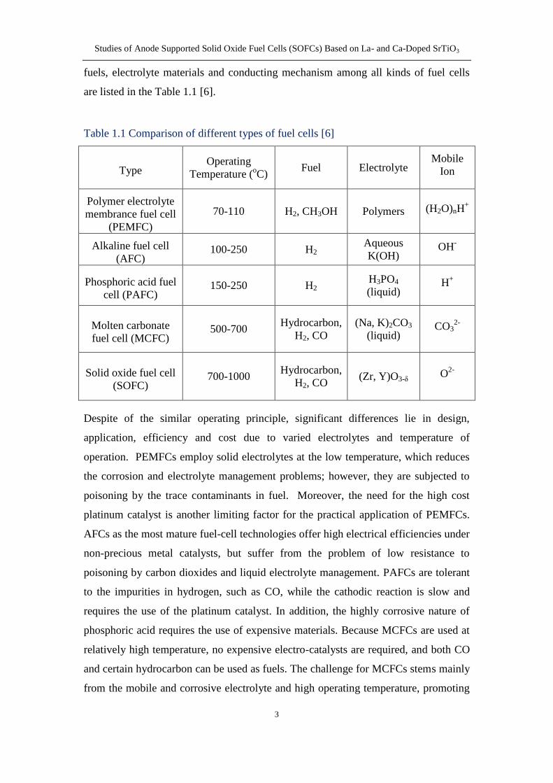
fuels electrolyte materials and conducting mechanism among all kinds of fuel cells
are listed in the Table 11 [6]
Table 11 Comparison of different types of fuel cells [6]
Type Operating
Temperature (oC)
Fuel Electrolyte Mobile
Ion
Polymer electrolyte
membrance fuel cell
(PEMFC)
70-110 H2 CH3OH Polymers (H2O)nH+
Alkaline fuel cell
(AFC) 100-250 H2
Aqueous
K(OH) OH
-
Phosphoric acid fuel
cell (PAFC) 150-250 H2
H3PO4
(liquid) H
+
Molten carbonate
fuel cell (MCFC) 500-700
Hydrocarbon
H2 CO
(Na K)2CO3
(liquid) CO3
2-
Solid oxide fuel cell
(SOFC) 700-1000
Hydrocarbon
H2 CO (Zr Y)O3-δ O
2-
Despite of the similar operating principle significant differences lie in design
application efficiency and cost due to varied electrolytes and temperature of
operation PEMFCs employ solid electrolytes at the low temperature which reduces
the corrosion and electrolyte management problems however they are subjected to
poisoning by the trace contaminants in fuel Moreover the need for the high cost
platinum catalyst is another limiting factor for the practical application of PEMFCs
AFCs as the most mature fuel-cell technologies offer high electrical efficiencies under
non-precious metal catalysts but suffer from the problem of low resistance to
poisoning by carbon dioxides and liquid electrolyte management PAFCs are tolerant
to the impurities in hydrogen such as CO while the cathodic reaction is slow and
requires the use of the platinum catalyst In addition the highly corrosive nature of
phosphoric acid requires the use of expensive materials Because MCFCs are used at
relatively high temperature no expensive electro-catalysts are required and both CO
and certain hydrocarbon can be used as fuels The challenge for MCFCs stems mainly
from the mobile and corrosive electrolyte and high operating temperature promoting
Studies of Anode Supported Solid Oxide Fuel Cells (SOFCs) Based on La- and Ca-Doped SrTiO3
4
material problems and causing the performance degradation upon operation SOFCs
are composed of solid components which alleviate the corrosion problems in the cell
The high operating temperature for SOFCs allows using low-cost electro-catalysts and
varied fuels but it places severe constraints on material selection and manufacturing
processes And the long-term reliability of the materials under operating conditions is
also of the greatest concern
The application of solid electrolyte precludes the need for corrosive liquid prompting
the development of PEMFCs and SOFCs The SOFC is more demanding than the
PEMFC from the standpoint of materials and has been developed for its potential
application arising from the flexibility of fuel from hydrogen to hydrocarbon then
further to CO higher energy conversion efficiency operated at high temperature and
less emission of pollutants compared to the conventional internal combustion engines
and other types of fuel cells
114 Advantages
One of the most attractive properties of fuel cells is their extremely high energy-
conversion efficiency which is superior to those conventional internal combustion
engines Because the fuel cells convert the chemical energy directly into the electrical
energy without thermal energy conversion as intermediate steps the conversion
efficiency is not confined by the Carnot cycle Theoretically the efficiency of fuel
cells is expected to be 40ndash60 when converting fuel to electricity [7] If the heat from
the fuel cell system can be captured and utilized the overall system efficiencies could
be up to 80ndash85 [7] For hydrogen fuelled fuel cells the only product is water Fuel
cells can eliminate CO emission in exhaust gases by converting into CO2 at high
operating temperature Besides those advantages fuel cells offer some additional
benefits such as quite operation long life expectancy and flexible size construction
Studies of Anode Supported Solid Oxide Fuel Cells (SOFCs) Based on La- and Ca-Doped SrTiO3
5
12 Basics of solid oxide fuel cells
121 Principles of operation
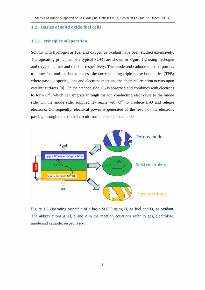
SOFCs with hydrogen as fuel and oxygen as oxidant have been studied extensively
The operating principles of a typical SOFC are shown in Figure 12 using hydrogen
and oxygen as fuel and oxidant respectively The anode and cathode must be porous
to allow fuel and oxidant to access the corresponding triple phase boundaries (TPB)
where gaseous species ions and electrons meet and the chemical reaction occurs upon
catalyst surfaces [8] On the cathode side O2 is absorbed and combines with electrons
to form O2-
which can migrate through the ion conducting electrolyte to the anode
side On the anode side supplied H2 reacts with O2-
to produce H2O and release
electrons Consequently electrical power is generated as the result of the electrons
passing through the external circuit from the anode to cathode
Figure 12 Operating principle of a basic SOFC using H2 as fuel and O2 as oxidant
The abbreviations g el a and c in the reaction equations refer to gas electrolyte
anode and cathode respectively
Porous anode
Solid electrolyte
Porous cathode
Studies of Anode Supported Solid Oxide Fuel Cells (SOFCs) Based on La- and Ca-Doped SrTiO3
6
122 Thermodynamic principles of SOFCs
In a typical SOFC device oxidant is reduced at the cathode side and fuel is oxidised
at the anode side If hydrogen and oxygen are used as fuel and oxidant in SOFC the
overall reaction in the fuel cell is given as
H2 (anode) + 12O2 (cathode) = H2O (anode) (Equation 11)
where the subscripts anode and cathode refer to the states at the anode and cathode
respectively
The reaction of oxygen and hydrogen occurs on the cathode and anode respectively
according to Equations (12) and (13)
O2 (cathode) + 4e- = 2O
2- (electrolyte) (Equation 12)
H2 (anode) + O2-
(electrolyte) = H2O (anode) + 2e-
(Equation 13)
where the subscript electrolyte represents the oxygen ions transporting through the
electrolyte
The equilibrium voltage E is given by the Nernst equation
0 2 anode2 cathode
2 anode
P(H )ln P(O ) ln
4 2 P(H O )
RT RTE E
F F (Equation 14)
Where R is the gas constant F the Faradayrsquos constant T the temperature and
2 cathodeP(O ) 2 anodeP(H ) and 2 anodeP(H O ) the partial pressure of cathodic oxygen
anodic hydrogen and water vapour respectively 0E is the equilibrium voltage at the
standard state for oxidation of H2 which can be established by
0 0 0
0
4 4
G H T SE
F F
(Equation 15)
where ∆G0 represents the standard Gibbs energy change of reaction of hydrogen with
oxygen to produce water ∆H0 is the standard enthalpy change and ∆S
0 is the standard
entropy However the actual cell voltage Ec under current load is less than the
theoretical Nernst value or electromotive force (EMF) due to the irreversible losses
Studies of Anode Supported Solid Oxide Fuel Cells (SOFCs) Based on La- and Ca-Doped SrTiO3
7
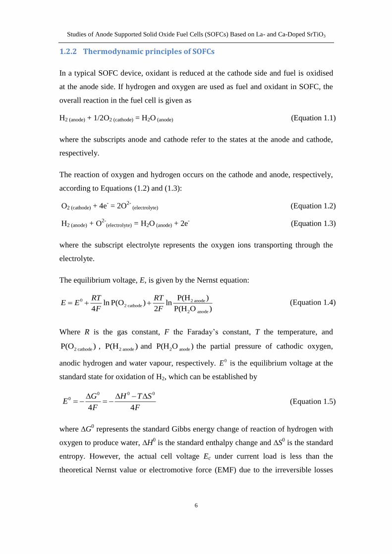
associated with ohmic losses mass transport and the kinetics of electrode reactions as
depicted in Figure 13 [9]
Figure 13 Schematic of a current-voltage curve with marked regions of the different
contribution of polarization losses Image is taken from reference [9]
The maximum thermodynamic efficiency can be obtained only when the Gibbs
free energy of the cell reaction G is totally converted into electrical energy
therein expressed by the following equation
G
H
(Equation 16)
where H is the enthalpy changes for the combustion of fuel In practise G is
consumed not only to achieve the cell reaction but also to produce heat and water
vapour above 100oC resulting in a significant energy losses compared to the
maximum efficiency
Studies of Anode Supported Solid Oxide Fuel Cells (SOFCs) Based on La- and Ca-Doped SrTiO3
8
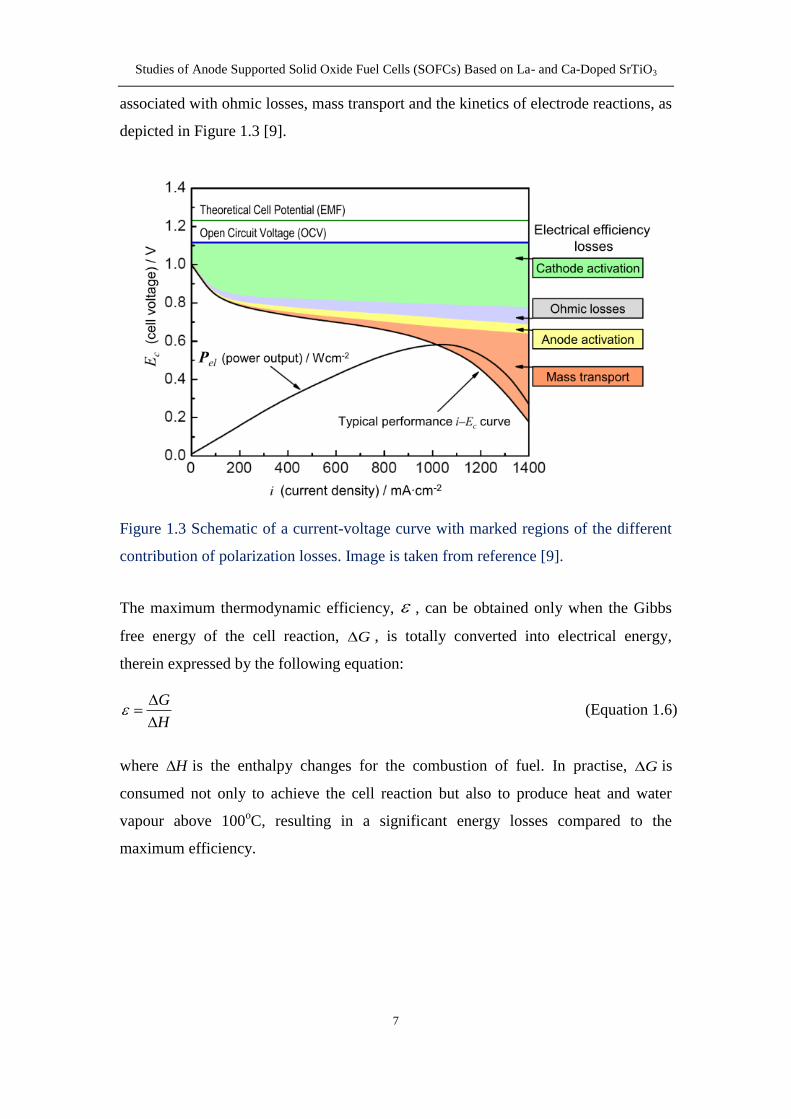
123 Configuration and evolution of SOFCs
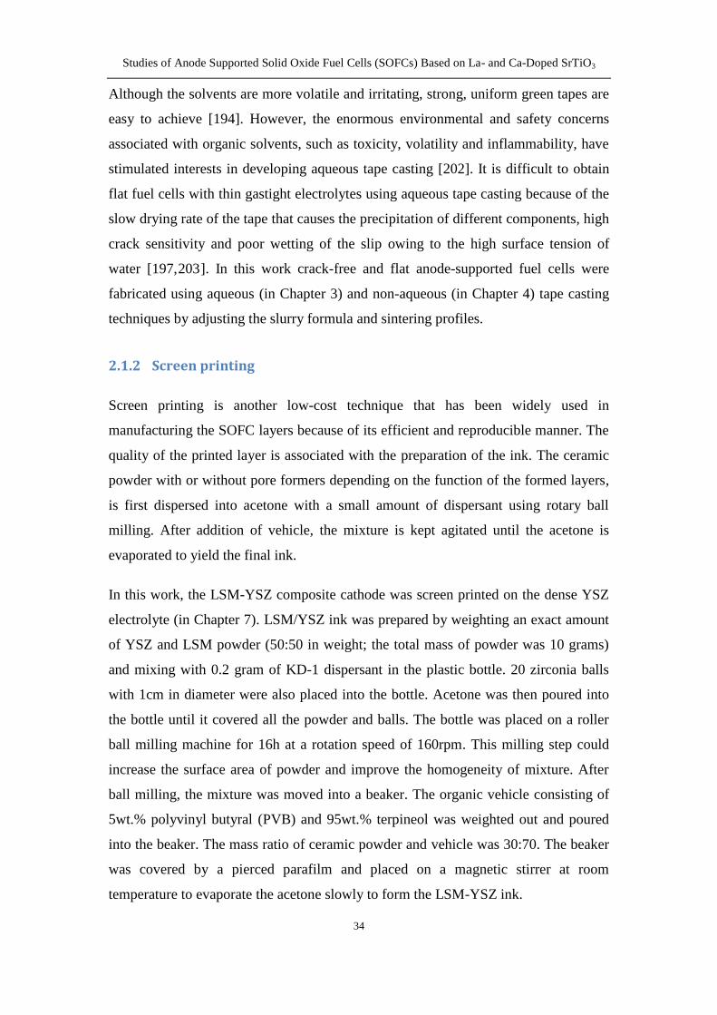
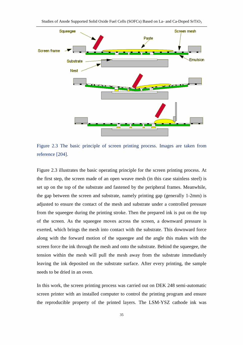
Figure 14 Planar design of SOFCs Image is taken from reference [10]
In general there are two types of SOFC designs planar and tubular In a planar cell
each component is made into flat plates and all components are assembled into a stack
by connecting the interconnect plates of two adjacent cells shown in Figure 14 In
this system the interconnect plates form gas flow channels for fuel and oxidant and
serve as bipolar gas separators contacting the anode and the cathode of adjoining cells
[11]
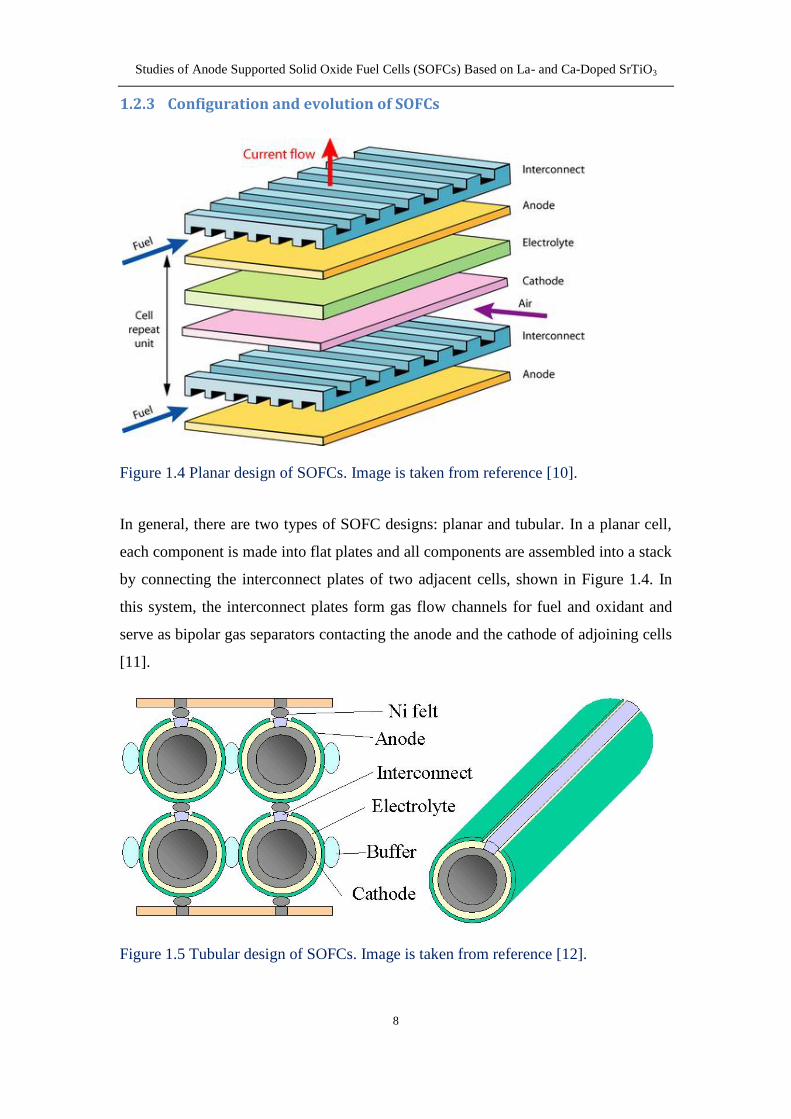
Figure 15 Tubular design of SOFCs Image is taken from reference [12]
Studies of Anode Supported Solid Oxide Fuel Cells (SOFCs) Based on La- and Ca-Doped SrTiO3
9
Another important type of SOFC configuration is tubular As illustrated in Figure 15
outside of one electrode is electrolyte and another electrode in order Generally one
electrode is fabricated into a long tube by extrusion and sintering and then the other
components are deposited as a thin layer on the electrode tube The main advantage of
this type of SOFC configuration is the elimination of gas-tight seal problem and
mechanical strength However the cell internal resistance and gas diffusion are the
limiting factors of this design [13]
The development of SOFCs can be divided into three stages according to operating
temperature The earlier SOFCs were based on electrolyte-supported fuel cells which
contain a thick yttria-stabilized zirconia (YSZ) layer as electrolyte operated at high
temperature up to 1000oC [14] The next generation involves an electrode-supported
fuel cell operating at intermediate temperature (600-800oC) and is the most widely
studied at present The benefits of lowering the operating temperature can be
summarized in the following ways 1) increasing the choice of materials such as
using metallic interconnect 2) the lower constraints imposed by the cell components
and seals 3) improved stability and durability [1516] Moreover an anode-supported
fuel cell is preferred due to the higher diffusivity of hydrogen than that of oxygen
through the electrodes with a similar porosity at intermediate temperatures [1718]
which will decrease the diffusion losses of the whole fuel cell The third generation
tends to be metal-supported cells which provide significant advantages over
conventional ceramic cells including low material cost ruggedness and tolerance to
rapid thermal cycling and redox cycling [19] They are believed to achieve a good
performance at lower temperature around 500-600oC as an alternative to the anode-
and electrolyte-supported cells [20~22]
13 Electrolyte materials for SOFCs
The electrolyte in SOFCs serves as a separator between the fuel and the oxidant and
an ionic conductor from the cathode to the anode In terms of its function the
electrolyte should satisfy several needs including efficient ionic conductivity
negligible electronic conductivity and good chemical stability over a broad range of
oxygen partial pressure and temperature
Studies of Anode Supported Solid Oxide Fuel Cells (SOFCs) Based on La- and Ca-Doped SrTiO3
10
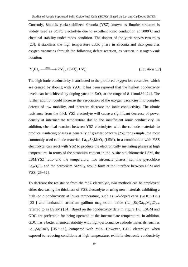
Currently 8mol yttria-stabilized zirconia (YSZ) known as fluorite structure is
widely used as SOFC electrolyte due to excellent ionic conduction at 1000oC and
chemical stability under redox condition The dopant of the yttria serves two roles
[23] it stabilizes the high temperature cubic phase in zirconia and also generates
oxygen vacancies through the following defect reaction as written in Kroger-Vink
notation
2ZrO
2 3 Zr O OY O 2Y +3O +V (Equation 17)
The high ionic conductivity is attributed to the produced oxygen ion vacancies which
are created by doping with Y2O3 It has been reported that the highest conductivity
levels can be achieved by doping yttria in ZrO2 at the range of 8-11mol [24] The
further addition could increase the association of the oxygen vacancies into complex
defects of low mobility and therefore decrease the ionic conductivity The ohmic
resistance from the thick YSZ electrolyte will cause a significant decrease of power
density at intermediate temperature due to the insufficient ionic conductivity In
addition chemical reaction between YSZ electrolytes with the cathode materials to
produce insulating phases is generally of greatest concern [25] for example the most
commonly used cathode material La1-xSrxMnO3 (LSM) in a combination with YSZ
electrolyte can react with YSZ to produce the electronically insulating phases at high
temperature In terms of the strontium content in the A-site stoichiometric LSM the
LSMYSZ ratio and the temperature two zirconate phases ie the pyrochlore
La2Zr2O7 and the perovskite SrZrO3 would form at the interface between LSM and
YSZ [26~32]
To decrease the resistance from the YSZ electrolyte two methods can be employed
either decreasing the thickness of YSZ electrolyte or using new materials exhibiting a
high ionic conductivity at lower temperature such as Gd-doped ceria (GDCCGO)
[ 33 ] and lanthanum strontium gallium magnesium oxide (La1-xSrxGa1-yMgyO3-δ
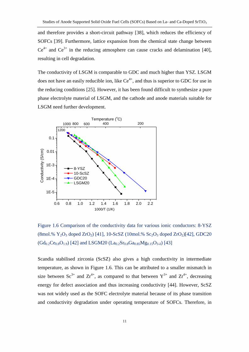
referred to as LSGM) [34] Based on the conductivity data in Figure 16 LSGM and
GDC are preferable for being operated at the intermediate temperature In addition
GDC has a better chemical stability with high-performance cathode materials such as
La1-xSrxCoO3 [ 35 ~ 37 ] compared with YSZ However GDC electrolyte when
exposed to reducing conditions at high temperature exhibits electronic conductivity
Studies of Anode Supported Solid Oxide Fuel Cells (SOFCs) Based on La- and Ca-Doped SrTiO3
11
and therefore provides a short-circuit pathway [38] which reduces the efficiency of
SOFCs [39] Furthermore lattice expansion from the chemical state change between
Ce4+
and Ce3+
in the reducing atmosphere can cause cracks and delamination [40]
resulting in cell degradation
The conductivity of LSGM is comparable to GDC and much higher than YSZ LSGM
does not have an easily reducible ion like Ce4+
and thus is superior to GDC for use in
the reducing conditions [25] However it has been found difficult to synthesize a pure
phase electrolyte material of LSGM and the cathode and anode materials suitable for
LSGM need further development
Figure 16 Comparison of the conductivity data for various ionic conductors 8-YSZ
(8mol Y2O3 doped ZrO2) [41] 10-ScSZ (10mol Sc2O3 doped ZrO2)[42] GDC20
(Gd02Ce08O19) [42] and LSGM20 (La02Sr08Ga085Mg015O3-δ) [43]
Scandia stabilised zirconia (ScSZ) also gives a high conductivity in intermediate
temperature as shown in Figure 16 This can be attributed to a smaller mismatch in
size between Sc3+
and Zr4+
as compared to that between Y3+
and Zr4+
decreasing
energy for defect association and thus increasing conductivity [44] However ScSZ
was not widely used as the SOFC electrolyte material because of its phase transition
and conductivity degradation under operating temperature of SOFCs Therefore in
06 08 10 12 14 16 18 20 22
1E-5
1E-4
1E-3
001
01
Co
nd
uctivity (
Sc
m)
1000T (1K)
8-YSZ
10-ScSZ
GDC20
LSGM20
1200
1000 800 600 400
Temperature (oC)
200
Studies of Anode Supported Solid Oxide Fuel Cells (SOFCs) Based on La- and Ca-Doped SrTiO3
12
order to decrease the ohmic loss a thin film of YSZ electrolyte typically 40-60m in
thickness was employed in this study
14 Cathode materials for SOFCs
The cathodes for SOFCs as the sites for oxygen reduction need to meet the following
requirements [45] 1) high electronic conductivity (preferably more than 100Scm
under oxidizing condition) 2) matched thermal expansion coefficients (TECs) with
electrolyte materials 3) good chemical compatibility with other cell components 4)
sufficient porosity for the gaseous species to diffuse to triple phase boundaries (TPBs)
5) good stability in oxidizing condition 6) high catalytic activity for oxygen reduction
Strontium-doped lanthanum manganite (LSM) has been known as the most commonly
used cathode material where substitution of lower valent strontium for lanthanum
enables to increase the content of Mn4+
in oxidizing atmospheres and therefore
enhances the electronic conductivity However the Sr dopant does not increase the
oxygen vacancies which can be explained by the following equation
3LaMnO
Mn La Mn OSrO Mn Sr Mn O (Equation 18)
This reaction increases the electron-hole concentration and therefore improves the
electrical conductivity under oxidizing atmosphere however this reaction also
suggests that LSM lacks sufficient oxygen ionic conductivity So the reduction of
oxygen in LSM is restricted to the interface between the electrolyte and the LSM
cathode where oxygen electrolyte and cathode are in intimate contact The limitation
of reaction sites has a great impact on the cell performance when using single phase
LSM as cathode
The addition of ionic conductor such as YSZ to LSM cathodes has been reported to
show a better performance than those composed of single phase LSM since the TPBs
for reduction of oxygen have been extended into the composite cathode three-
dimensionally [46~49] In general the LSM-YSZ composite is prepared by screen-
printing onto the YSZ electrolyte with the inks that contain the LSM YSZ and pore
formers followed by a calcination step to sinter the cathode onto the electrolyte [50]
Studies of Anode Supported Solid Oxide Fuel Cells (SOFCs) Based on La- and Ca-Doped SrTiO3
13
The calcination temperature should be high enough to yield good LSM particle
percolation but not so high as to cause substantial particle coarsening and
densification [51] Choi et al [52] reported that the optimal firing temperature for the
LSM-YSZ composite was 1100oC when the composite offers the optimum cathodic
performance by compromising the interfacial resistance and the TPB sites In addition
infiltration of the nanoparticles of LSM into the porous YSZ backbone has been
demonstrated as an effective method to produce the connected electronic and ionic
transporting networks for SOFC cathodes [5053~56]
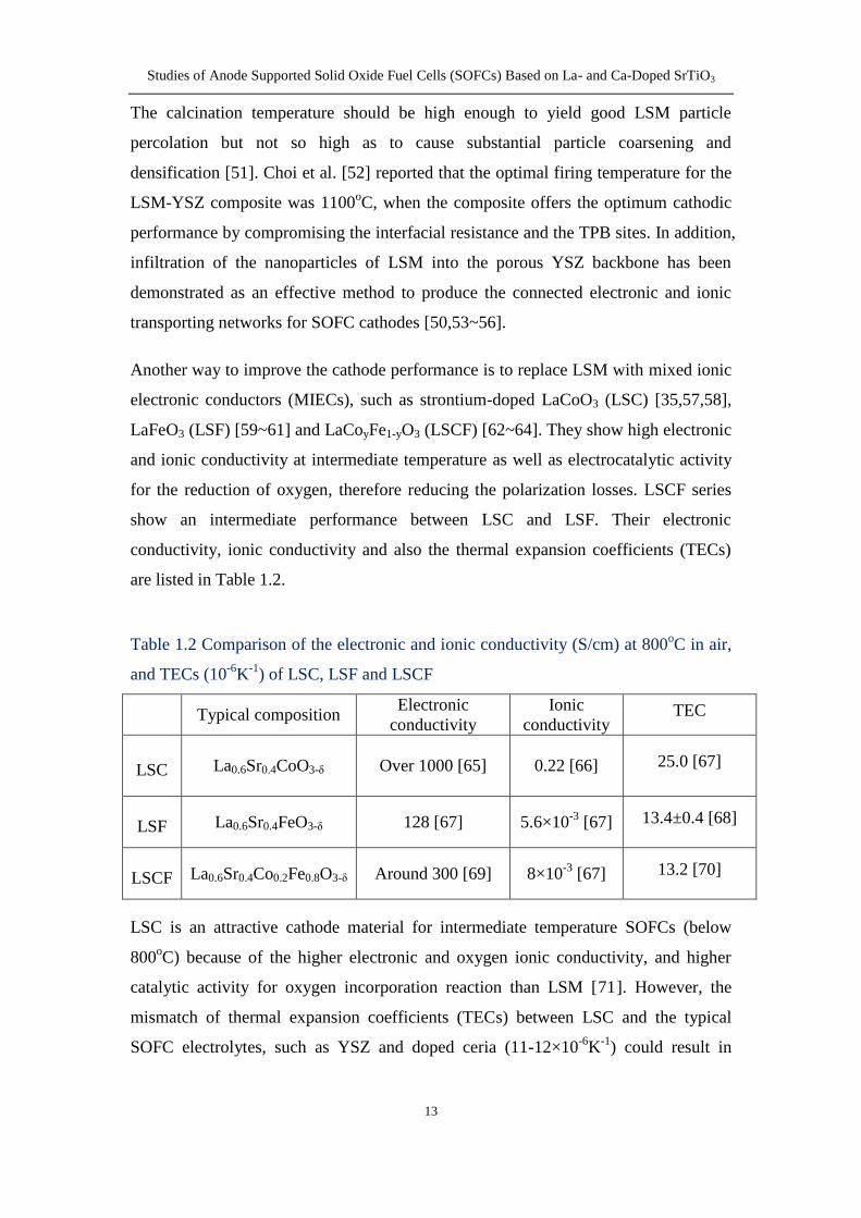
Another way to improve the cathode performance is to replace LSM with mixed ionic
electronic conductors (MIECs) such as strontium-doped LaCoO3 (LSC) [355758]
LaFeO3 (LSF) [59~61] and LaCoyFe1-yO3 (LSCF) [62~64] They show high electronic
and ionic conductivity at intermediate temperature as well as electrocatalytic activity
for the reduction of oxygen therefore reducing the polarization losses LSCF series
show an intermediate performance between LSC and LSF Their electronic
conductivity ionic conductivity and also the thermal expansion coefficients (TECs)
are listed in Table 12
Table 12 Comparison of the electronic and ionic conductivity (Scm) at 800oC in air
and TECs (10-6
K-1
) of LSC LSF and LSCF
Typical composition Electronic
conductivity
Ionic
conductivity TEC
LSC La06Sr04CoO3-δ Over 1000 [65] 022 [66] 250 [67]
LSF La06Sr04FeO3-δ 128 [67] 56times10-3
[67] 134plusmn04 [68]
LSCF La06Sr04Co02Fe08O3-δ Around 300 [69] 8times10-3
[67] 132 [70]
LSC is an attractive cathode material for intermediate temperature SOFCs (below
800oC) because of the higher electronic and oxygen ionic conductivity and higher
catalytic activity for oxygen incorporation reaction than LSM [71] However the
mismatch of thermal expansion coefficients (TECs) between LSC and the typical
SOFC electrolytes such as YSZ and doped ceria (11-12times10-6
K-1
) could result in
Studies of Anode Supported Solid Oxide Fuel Cells (SOFCs) Based on La- and Ca-Doped SrTiO3
14
cracking and delamination of cell components due to the stress developed during
fabrication and operation [72] Moreover a highly reactivity between YSZ electrolyte
and LSC cathode forming insulting phases such as La2Zr2O7 and SrZrO3 is another
drawback hindering its development [6173] when using YSZ as electrolytes In order
to minimize the mismatch of TECs between the LSC and electrolyte materials the
efforts have been made by incorporating LSC into ceria-based cathode backbone to
form a composite cathode [7174] on ceria-based or LSGM electrolytes
Despite the lower electronic and ionic conductivity than LSC LSF exhibits a closely
matched TEC with commonly used electrolyte materials [68] such as YSZ and GDC
and no detrimental reaction occurs between LSF and YSZ [ 75] under sintering
conditions
In order to achieve a desirable electrochemical performance along with chemical and
mechanical compatibility with electrolyte materials such as YSZ and GDC the
combination of LSC and LSF was proposed by incorporating strontium in the A site
and cobalt in the B site on the perovskite LaFeO3 known as La1-xSrxCoyFe1-yO3
(LSCF) Previous research [76~79] has shown that the properties such as ionic and
electronic conductivity TEC and reactivity with the YSZ electrolyte are related with
the composition namely the content of Sr and Co The electrical and ionic
conductivities increased with increasing Sr andor Co content and they show the
highest value for the composition La02Sr08Co08Fe02O3 However the increasing Sr
and Co content causes an increase in thermal expansion gt26times10-6
K-1
which is not
compatible with the commonly used electrolytes Therefore the composition with
02ltxlt04 and ylt05 seem to be more attractive as cathode material for SOFCs
Moreover in order to prevent the undesired chemical reactions between LSCF
cathode and YSZ electrolyte two effective methods have been investigated to
employ GDC as an interlayer [6364] or prepare the cathode at the low temperature
[8081] It has been reported that no impurity phase is observed when LSCF is formed
on the YSZ skeleton after firing at 800oC [81]
Studies of Anode Supported Solid Oxide Fuel Cells (SOFCs) Based on La- and Ca-Doped SrTiO3
15
15 Anode materials for SOFCs
151 Requirements for anode
Based on the operation principle and laminated structure an anode material must
meet some requirements to function efficiently [82]
1) High electronic conductivity The electrons produced from oxidation of fuel on the
triple phase boundaries (TPBs) on the anode where electrons oxygen ions and fuel
meet together and react need to be transported to the external circuit The thicker the
anode layer is the longer distance electrons travel through the anode to current
collector and therein the higher electronic conductivity the anode requires
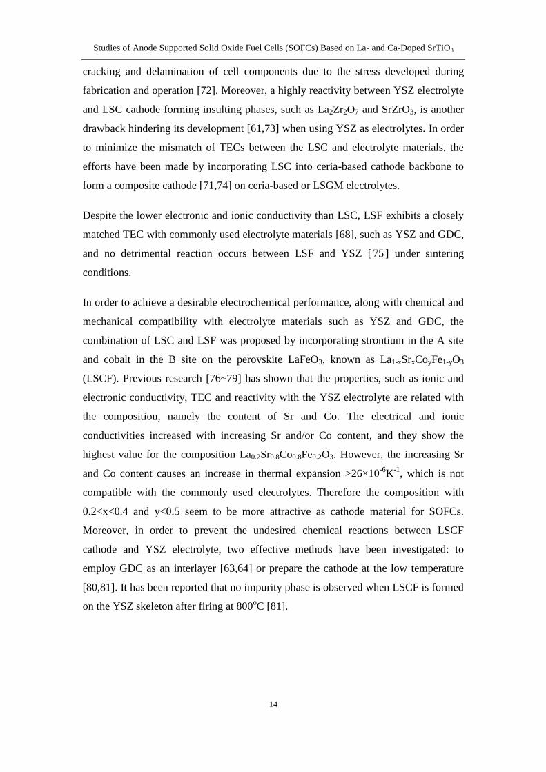
Figure 17 Schematic of the sites where the electrochemical reaction occurs for
different types of anode (a) metal (b) Ni-YSZ cermet and (c) MIEC The yellow
blue and green spheres represent Ni YSZ and MIEC particles respectively The pink
areas indicate TPBs where the oxidation of fuel takes place
2) High oxygen ionic conductivity Three types of materials have been employed as
anode for SOFCs metal (such as Pt and Ni) Ni-YSZ cermet and mixed ionic and
electronic conductor (MIEC such as Gd-doped ceria) Take metal anode as example
as shown in Figure 17(a) the electrochemical reaction only takes place at the
interface of electrolyteanode (1-D) For the Ni-YSZ as anode the TPBs spread out
over the NiYSZ particle interface within the bulk anode (in Figure 17(b)) When
MIEC being used as anode the electrochemical reaction is more likely to occur at the
surface area of anode particles (2-D) as the fuel reaches shown in Figure 17(c) It is
Studies of Anode Supported Solid Oxide Fuel Cells (SOFCs) Based on La- and Ca-Doped SrTiO3
16
clear that the sites where the electrochemical reaction occurs are increased
significantly by applying mixed ionic electronic conductor as anode
3) High catalytic activity for the oxidation reaction of the fuel The oxidation of
hydrogen and hydrocarbon on the anode begins with a chemisorption and dissociation
then followed by a reaction of the products from the dissociation with O2-
from the
electrolyte [83] The catalyst plays an important role in facilitating these reactions to
occur
4) Chemical stability The anode is required to be chemically stable not only in the
reducing and oxidizing atmospheres but also with the electrolyte and current collector
in contact with anode
5) Thermal compatibility with the contacting components The thermal expansion of
the anode must match that of the electrolyte and current collector during heating stage
and reduction-oxidation (redox) cycles Otherwise the delamination and cracking of
the cell components can be induced by the mismatch resulting in failure for operation
of the fuel cell
6) Porosity Because the gaseous species must transport to the TPBs of the anode and
meet the electron and oxygen ions the anode need to retain a porous structure during
operation to allow the fuel into and the products out of the anode
152 Ni-YSZ cermet anodes
For SOFCs based on YSZ electrolyte Ni(O)-YSZ cermets are the-state-of-the-art
materials for anode [8485] In this composite YSZ phase acts as a supporting matrix
for metal phase ensuring a uniform dispersion of nickel particles and inhibiting
coarsening of nickel [86] the Ni phase provides the electronic conducting pathways
and catalytic activity for hydrogen oxidation
Because the TECs of Ni metal and NiO are 169times10-6
and 142times10-6
oC [ 87 ]
respectively much larger than that of YSZ (109times10-6
oC)
[88] which has potential to
cause mechanical stresses on the cells especially upon thermal cycles lowering Ni
content will effectively decrease thermal expansion of anode and make it more
Studies of Anode Supported Solid Oxide Fuel Cells (SOFCs) Based on La- and Ca-Doped SrTiO3
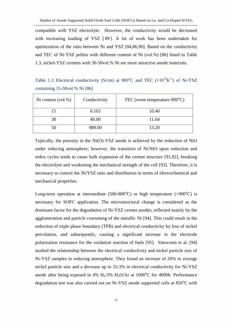
17
compatible with YSZ electrolyte However the conductivity would be decreased
with increasing loading of YSZ [ 89 ] A lot of work has been undertaken for
optimization of the ratio between Ni and YSZ [848690] Based on the conductivity
and TEC of Ni-YSZ pellets with different content of Ni (vol) [86] listed in Table
13 nickel-YSZ cermets with 30-50vol Ni are more attractive anode materials
Table 13 Electrical conductivity (Scm) at 900oC and TEC (times10
-6K
-1) of Ni-YSZ
containing 15-50vol Ni [86]
Ni content (vol) Conductivity TEC (room temperature-900oC)
15 0103 1040
30 4000 1164
50 98900 1320
Typically the porosity in the Ni(O)-YSZ anode is achieved by the reduction of NiO
under reducing atmosphere however the transition of NiNiO upon reduction and
redox cycles tends to cause bulk expansion of the cermet structure [9192] breaking
the electrolyte and weakening the mechanical strength of the cell [93] Therefore it is
necessary to control the NiYSZ ratio and distribution in terms of electrochemical and
mechanical properties
Long-term operation at intermediate (500-800oC) or high temperature (gt900
oC) is
necessary for SOFC application The microstructural change is considered as the
dominant factor for the degradation of Ni-YSZ cermet anodes reflected mainly by the
agglomeration and particle coarsening of the metallic Ni [94] This could result in the
reduction of triple phase boundary (TPB) and electrical conductivity by loss of nickel
percolation and subsequently causing a significant increase in the electrode
polarization resistance for the oxidation reaction of fuels [95] Simwonis et al [94]
studied the relationship between the electrical conductivity and nickel particle size of
Ni-YSZ samples in reducing atmosphere They found an increase of 26 in average
nickel particle size and a decrease up to 333 in electrical conductivity for Ni-YSZ
anode after being exposed in 4 H23 H2OAr at 1000oC for 4000h Performance
degradation test was also carried out on Ni-YSZ anode supported cells at 850oC with
Studies of Anode Supported Solid Oxide Fuel Cells (SOFCs) Based on La- and Ca-Doped SrTiO3
18
air and humidified H2 (3 H2O) as oxidant and fuel respectively [96] The results
show that both the cell voltage decay and the Ni growth appear to reach a plateau after
about 800h operation presenting a strong relationship between degradation and the
coarsening of Ni particles occurring in the anode
When using hydrocarbon fuels more disadvantages can be found on Ni-YSZ anodes
such as low tolerance to sulphur poisoning [97] and carbon deposition [9899]
besides the redox instability and nickel coarsening mentioned above Sulfur is a
common compound in conventional and low-cost hydrocarbon fuels Upon reforming
sulfur compounds are converted into hydrogen sulphide (H2S) which inhibits the
rapid catalysis of nickel-YSZ anode leading to a drastic drop of cell performance and
lifetime [100] One hypothesis has been generally acknowledged that the sulfur
poisoning is caused by the strong adsorption of the elemental sulphur on Ni surface
which blocks the active sites for oxidation of fuel and degrades the cell performance
[90100~103]
Carbon is another harmful species that can deposit on the metal surface and block the
reaction sites at the triple phase boundary (TPB) increasing the mass transport
resistance and reducing the cell performance [ 104 105 ] Buccheri et al [ 106 ]
conducted the cell testing in dry methane at 750oC on electrolyte- and anode-
supported Ni-YSZYSZPt cells a remarkable degradation is observed for both cells
possibly due to carbon damaging the anode and blocking pores The Ni-YSZ
supported cells have shown a rapid degradation from 10V to zero in dry methane at
100mAcm2 within 10h operation due to coking [ 107 ] However the carbon
deposition might be oxidized at high current density due to sufficient oxygen supply
from ionic conductor presented as reversible carbon deposition [99]
153 Modified Ni-YSZ based anodes
Two approaches have been proposed to solve the problems of Ni-YSZ cermet anode
stated above [108] one is to replace Ni by other catalytic materials and the other is to
modify the existing structure by alloying Ni with less active elements or decorating Ni
surface with lower surface energy oxides
Studies of Anode Supported Solid Oxide Fuel Cells (SOFCs) Based on La- and Ca-Doped SrTiO3
19
Since Cu is known to be a poor catalyst for C-C bond breaking and formation Cu has
been considered as an alternative to Ni for SOFC anode Although Cu-YSZ cermets
were found to be stable in hydrocarbon environments they exhibited low performance
for direct oxidation of hydrocarbon [109110] The Cu-YSZ anode performance can
be significantly improved by addition of ceria due to its catalytic property and ionic
conductivity [111] however agglomeration and growth of Cu particles is still the
dominant factor for performance degradation in hydrogen [112]
The partial substitution of Ni with other metals is believed to be an alternative to
reduce coarsening of the metallic particles and also achieve good performance
Ringuedeacute et al [113~115] have successfully prepared homogeneous mixture of
nanocrystalline powders of (Ni Co)-YSZ (Ni Cu)-YSZ and (Ni Fe)-YSZ by
combustion synthesis from mixtures of molten nitrates and urea After reduction at
973K the Cu-Ni mixtures in the porous YSZ scaffold formed single-phase alloys
[116] and showed an excellent tolerance for carbon formation in dry methane at
1073K [117] Especially Cu (80)ndashNi (20) cermet showed a significant increase in
power density with time during operation in dry methane for 500h due to enhanced
electronic conductivity in the anode [117] The same behaviour has been observed in
Cu electroplated Ni-YSZ cermet anode Cu-Ni-YSZ anode supported single cell
shows a slightly lower performance but a more enhanced durability in methane than
those of Ni-YSZ anode supported single cell [ 118 ] Compared with Ni-SDC
(Ce08Sm02O19) anodes tri-metal alloys Fe025Co025Ni05-SDC (Ce08Sm02O19) anodes
show a higher power density and a lower polarization resistance [119] So far the
improved electrochemical performance has been attributed to the alloy formation and
surface reconstruction effects of the binaryternary electrocatalysts
The surface modification on the Ni-YSZ surface with low-energy oxides such as
Nb2O5 and CeO2 can effectively improve the sulphur tolerance on the anode
[120~122] A thin layer of the ceria or Nb2O5 nanoparticles on the Ni-YSZ anode
surface can react with H2S as a sulphur sorbent to form oxysulfide which prohibits
the absorption of sulphur by nickel to form the harmful phase Ni3S2 Compared with
the bare Ni-YSZ anode the modified Ni-YSZ anode demonstrates a more stable
performance over 500 hours when exposed to the sulphur-containing H2 fuel [123]
Studies of Anode Supported Solid Oxide Fuel Cells (SOFCs) Based on La- and Ca-Doped SrTiO3
20
154 SrTiO3 (STO)-based perovskite anodes
Since the drawbacks of Ni-YSZ cermet anodes restrict the development and
application for SOFCs some alternative anode materials have been extensively
studied and reported One of the most promising anode materials is titanate perovskite
with general formula ABO3 because of the multiple oxidation states of titanium
(Ti4+
Ti3+
) providing a high electronic conductivity under reducing conditions Of the
available titanates strontium titanium oxide SrTiO3 (STO) has been extensively
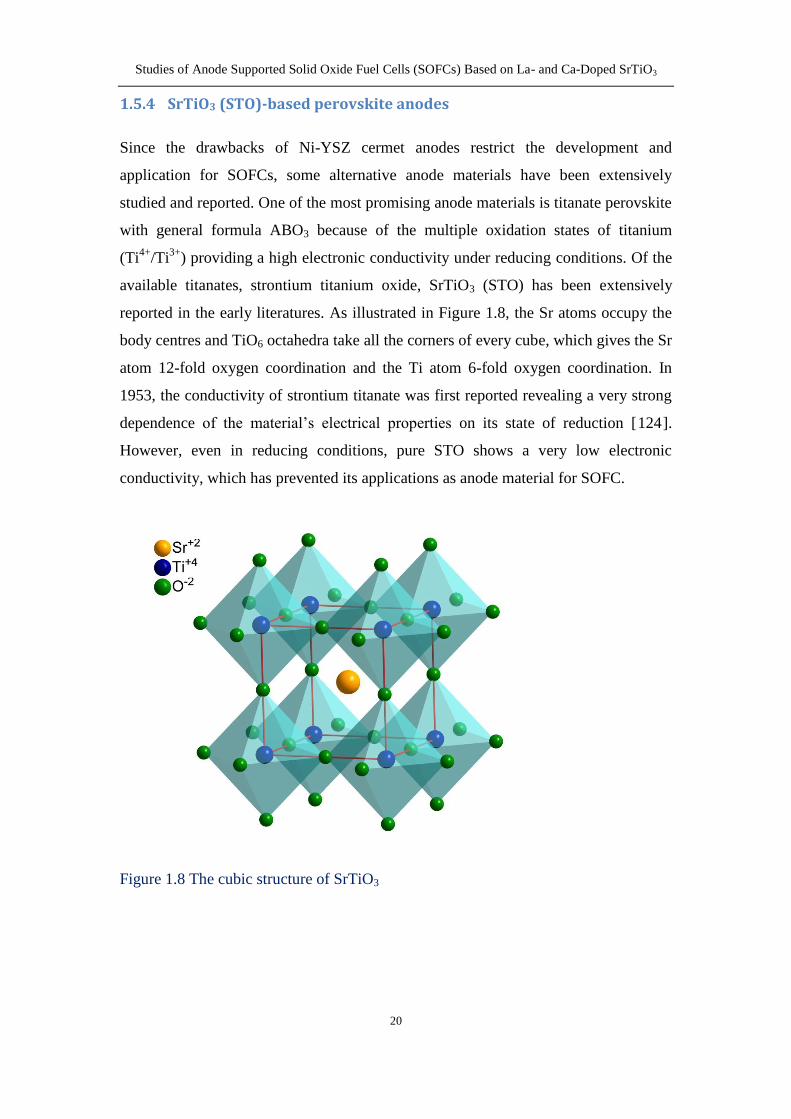
reported in the early literatures As illustrated in Figure 18 the Sr atoms occupy the
body centres and TiO6 octahedra take all the corners of every cube which gives the Sr
atom 12-fold oxygen coordination and the Ti atom 6-fold oxygen coordination In
1953 the conductivity of strontium titanate was first reported revealing a very strong
dependence of the materialrsquos electrical properties on its state of reduction [124]
However even in reducing conditions pure STO shows a very low electronic
conductivity which has prevented its applications as anode material for SOFC
Figure 18 The cubic structure of SrTiO3
Studies of Anode Supported Solid Oxide Fuel Cells (SOFCs) Based on La- and Ca-Doped SrTiO3
21
1541 A-site doped SrTiO3
Strontium titanate can be converted into a highly semiconducting material by doping
with higher valent cation on the Sr site [125~127] Promising results have been
achieved with lanthanum strontium titanate (LST) In order to maintain the electro-
neutrality the substitution of Sr2+
with La3+
can be compensated by introducing the
extra oxygen beyond the ABO3 stoichiometry under oxidizing conditions defined as
lsquooxygen excessrsquo as in the formula LaxSr1-xTiO3+x2 or creating A-site vacancies as in
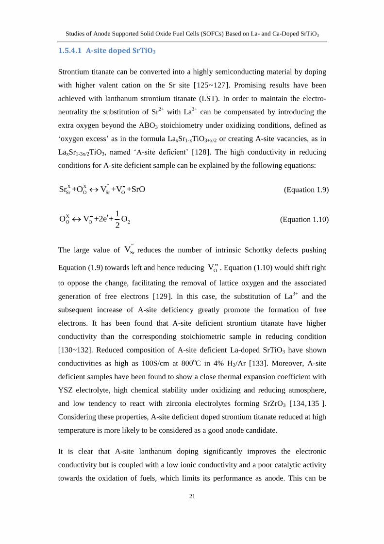
LaxSr1-3x2TiO3 named lsquoA-site deficientrsquo [128] The high conductivity in reducing
conditions for A-site deficient sample can be explained by the following equations
X X
Sr O Sr OSr +O V +V +SrO (Equation 19)
X
O O 2
1O V +2e + O
2 (Equation 110)
The large value of SrVreduces the number of intrinsic Schottky defects pushing
Equation (19) towards left and hence reducing OV Equation (110) would shift right
to oppose the change facilitating the removal of lattice oxygen and the associated
generation of free electrons [129] In this case the substitution of La3+
and the
subsequent increase of A-site deficiency greatly promote the formation of free
electrons It has been found that A-site deficient strontium titanate have higher
conductivity than the corresponding stoichiometric sample in reducing condition
[130~132] Reduced composition of A-site deficient La-doped SrTiO3 have shown
conductivities as high as 100Scm at 800oC in 4 H2Ar [133] Moreover A-site
deficient samples have been found to show a close thermal expansion coefficient with
YSZ electrolyte high chemical stability under oxidizing and reducing atmosphere
and low tendency to react with zirconia electrolytes forming SrZrO3 [134135 ]
Considering these properties A-site deficient doped strontium titanate reduced at high
temperature is more likely to be considered as a good anode candidate
It is clear that A-site lanthanum doping significantly improves the electronic
conductivity but is coupled with a low ionic conductivity and a poor catalytic activity
towards the oxidation of fuels which limits its performance as anode This can be
Studies of Anode Supported Solid Oxide Fuel Cells (SOFCs) Based on La- and Ca-Doped SrTiO3
22
illustrated by the poor performance for the cells using LST as anode [136~138] In
order to achieve a good combination of ionic and electronic conductivity the cells
with LST and YSZ as anode matrix phase was investigated for the potential use as
anode for SOFCs [139~141]
Moreover the catalytic activity for hydrogen oxidation can be optimized significantly
by the incorporation of various transition metals as well as ceria to porous ceramic
anodes The use of nickel has been found to improve the cell performance
significantly with an almost five times increase in the maximum powder density
observed in an LST-GDC anode at 800oC in 97 H2+3 H2O[142] When CeO2 and
Ni were used as impregnates a remarkable improvement of the anode performance
was observed compared with the anode using pure lanthanum strontium calcium
titanate (LSCTA-) or impregnated with ceria only at 900oC in pure hydrogen with 1
H2O [143144] The amount of catalyst incorporation into a porous anode can also
have an important effect on the fuel cell performance The cermet of 10wt NiYST-
YSZ showed the minimal polarization resistance among nickel concentrations ranging
from 5 to 50wt and stable cell performance even after five consecutive redox cycles
operated at 1000oC in humidified hydrogen (06 H2O) [145] Sun and Fan et al
[136146] have also found that the addition of ceriaGDC can significantly improve
the anode structure and thus fuel cell performance A-site deficient Y007Sr0895TiO3-δ
(YST) with infiltration of 3wt NiO exhibited a cell performance of over 10Acm-2
at 07V and 800oC in dry hydrogen which already reached the practical application
level [147] Recently the nano-scale electrocatalytic active particles exsoluted from
the doped LST matrix is regarded to be an effective way to promote the anode
performance dramatically and prevent the sintering and agglomeration of
nanoparticles under redox cycles and operation at high temperature [148~153]
While nickel is found to show the highest catalytic activity for oxidation of hydrogen
other metals are also found to present sufficient catalytic activity and good resistance
against sulphur poisoning especially combined with ceria or gadolinia-doped ceria
(GDC) Savaniu et al [154~157] have studied La02Sr07TiO3 anode impregnated with
20mol GDC and copper demonstrating that power densities in excess of 05Wcm-2
can be achieved at 750oC using humidified hydrogen (3 H2O) as fuel Kurokawa et
Studies of Anode Supported Solid Oxide Fuel Cells (SOFCs) Based on La- and Ca-Doped SrTiO3
23
al [158] have reported that the ceria- and Ru-infiltrated YST-YSZ anode showed a
high sulphur tolerance in 10-40ppm H2S and drastically decreased the polarization
resistance from 29Ωcm-2
for the non-infiltrated cell to 05Ωcm-2
at 800oC in 3
humidified hydrogen The combination of ceria and Pd has been demonstrated as an
effective catalyst to improve the cell performance on LSTM (La04Sr06Ti08Mn02O3)
[159160] and LST-YSZ [161] anode Samaria-doped ceria (SDC) is also discovered
to be more effective in both electrical conductivity and electrocatalytic activity
towards the oxidation of fuels than YSZ resulting in a relatively higher performance
of 140mWcm-2
for NiYST-SDC compared with that of NiYST-YSZ (115mWcm-2
)
in 1000oC using humidified H2 (3 H2O) as fuel [162]
1542 B-site doped SrTiO3
Many efforts have also been devoted to enhancing the electronic conductivities of
SrTiO3 materials by the replacement of Nb in B site The substitution of pentavalent
Nb5+
for the host cation Ti4+
has been reported to drastically enhance the electronic
conductivity by an increased electronic compensation due to the formation of Ti3+
and
Nb4+
[ 163 164 ] Blennow et al [ 165 ] studied Nb-doped SrTiO3 (STN
Sr094Ti09Nb01O3-δ) as a SOFC anode material in terms of electrochemical properties
and redox stability showing a promising redox stability feature However the ionic
conductivity of STN pre-reduced at 980oC was insufficient as an anode when
compared with the composite electrode of YSZ and STN As expected the
electrochemical performance of the anode was greatly improved with increasing Ni-
CGO loadings and showed a strong dependence on the structural parameters of the
electrode (porosity pore size etc) [166] Similarly Ni-CGO infiltrated STNFeCr
composite anode showed a comparable performance and promising durability
properties 07Acm2 was recorded under 06V at 650
oC in 4 humidified hydrogen
for the button cell with active surface area of 05cm2
[167] Ramos et al [168]
reported a preliminary comparison of the impact of catalyst M Ni Pd Ru on the
impedance and stability of MGDC co-infiltrated STNYSZ SOFC anodes They
found that the total polarization resistance (Rp) decreased in the order NiGDC gtgt
PdCGO gt RuCGO and RuCGO stayed reproducibly around 20mΩcm2 over 200h at
850oC 50 H2OH2 while NiCGO degraded by a factor of 3 in an equivalent period
Studies of Anode Supported Solid Oxide Fuel Cells (SOFCs) Based on La- and Ca-Doped SrTiO3
24
An alternative approach has been proposed by partially substituting the reducible
lower-valence transition metal cations for the Ti4+
cations which may not only
improve the electronic conductivity but also introduce oxygen vacancies that lead to
significant ionic conductivity [169] Rothschild et al [170] studied the electronic
structure defect chemistry and transport properties of mixed ionic electronic
conducting SrTi1-xFexO3-y (STF) STF exhibited mixed ionic and electronic
conductivity at elevated temperatures with a predominant transformation from p-type
conductor at high oxygen partial pressure (cathode condition) to n-type conductor at
low oxygen partial pressure (anode condition) The test of an LSGM electrolyte-
supported cell with SrTi1-xFexO3-y (x=0 04 and 07) mixed with GDC as anode
La04Ce06O2 as barrier layer and LSCF as cathode indicates that the Fe-containing
anodes yielded much lower total cell resistance and higher performance than SrTiO3
[169] A maximum power density of 337mWcm2 can be achieved for the
SrTi03Fe07O3-δ-GDC anode cell with thick LSGM electrolyte (06mm) at 800oC in ~3
H2O97 H2
1543 A- and B-site co-doped SrTiO3
In recent years (La)SrTiO3-based oxides doped with various transition metal
elements (Cr Co Mn Ni Mg etc) on the B site have also been developed in order to
optimize the electronic andor ionic conductivity It is generally acknowledged that
donor doping in the Sr site tends to increase the electrical conductivity while acceptor
doping in the Ti site has the possibility to improve the ionic conductivity [127130] In
addition B-site transition metal may provide the catalytic activity to promote the fuel-
oxidation processes
Danilovic et al [ 171 ] have investigated a series of perovskite oxides
La075Sr025Cr05X05O3-δ (LSCX X=Co Fe Ti Mn) as solid oxide fuel cell
electrocatalysts The Ti-containing composition showed the minimum fuel cell
performance in methane and hydrogen due to the lowest catalytic conversion for fuels
from Ti among all the doped transition metals while all the compositions provided
the sufficient electronic conductivity in reducing atmosphere In addition it was
found that the cell performance can be considerably improved by the addition of GDC
Studies of Anode Supported Solid Oxide Fuel Cells (SOFCs) Based on La- and Ca-Doped SrTiO3
25
at least due to the additional ionic conductivity imparted by the mixed conductor
GDC
It has been known that the general trend of catalytic activity for the transition metals
is found to be in the order Co gt Mn gt Cr on the oxidation-reduction process [127172]
The effect of Co doping in YST (YSTCo) on the electrical and ionic conductivity has
been studied [173] It was well noted that the addition of Co in LST or YST improves
remarkably the ionic conductivity and catalytic activity for fuel oxidation of A-site
doped SrTiO3 making it a potential candidate for SOFC anode The electrical
conductivities of YSTCo samples decrease with Co-doping amount while the ionic
conductivities increase up to 4mol Co doped in B site At 800oC in 5 H2-Ar
atmosphere 4mol Co-containing composite exhibited a total electrical conductivity
of 20Scm and an ionic conductivity of 16times10-3
Scm Yoo et al [172] have found that
1-2mol Co doping in LST (LSTCo) reduced significantly the polarization
resistance and improved the stability under operation An encouraging performance of
250mWcm2 at 800
oC using 97 H2 + 3 H2O as fuel was achieved for Ni-
impregnated LSTCo-GDC anode on LSGM electrolyte-supported cell Similar results
have also been found by Cui et al [153] they reported that after pre-reduction at
900oC in reducing condition both LST and LSTCo were active for the oxidation of
hydrogen and the Co substitution significantly improved the cell performance
(230mWcm2 for LSTCo vs 90mWcm
2 for LST at 900
oC in pure hydrogen)
The substitution of Mn on the Ti site for LST (LSTM) can also improve its catalytic
activity and stabilize the perovskite lattice by Mn valence (+4 +3 +2) change with
the oxygen partial pressure [ 174 ~ 176 ] While possessing adequate electronic
conductivity LSTM presents a very low ionic conductivity that is insufficient to
obtain a reasonable TPB length as a functional SOFC anode [177] Therefore it is
necessary to use a composite of LSTM and YSZ in anode application Although a
higher performance of LSTM-YSZ than LST-YSZ anode at 800oC was achieved
[140] the addition of CeO2 could decrease significantly the polarization values of
LSTM-YSZ anode because of the catalytic activity as well as the extended TPBs with
LSTM by creating more electronic percolation paths [159160]
Studies of Anode Supported Solid Oxide Fuel Cells (SOFCs) Based on La- and Ca-Doped SrTiO3
26
The pure phase La and Cr co-doped SrTiO3 (LSTC La03Sr055Ti1-xCrxO3-δ) was
synthesized using citric acid-nitrate process with a chromium dopant up to 20mol
[178] But the electronic conductivity of La03Sr055Ti08Cr02O3-δ pellet need to be
further improved if LSTC is considered as an anode material Du et al [137] studied
the electrical conductivity and redox stability of La03Sr07Ti1-xCrxO3-δ synthesized by
conventional solid-state reaction method and then sintered in 5 H2Ar at 1500oC for
10h It was found that the total electrical conductivity decreased with Cr doping level
(230Scm for LST vs 53Scm for x = 02 composition at 800oC in 5 H2-Ar) which
can be attributed to the reduction in the concentration of charge carrier from the direct
substitution of Cr3+
for Ti3+
16 Direct oxidation of hydrocarbon
The direct utilisation of hydrocarbon fuels is one of the most attractive advantages for
SOFCs because the use of natural gas could save the investment on infrastructure for
H2 Upon operation the oxygen anions migrate through the ionic conducting
electrolytes from the cathode to the anode where the direct oxidation of fuels occurs
For example alkane CnH2n+2 is used as fuel with the reaction as follows
2
n 2n 2 2 2C H (3n 1)O nCO +(n +1)H O +(6n + 2)e
(Equation 111)
The reduction of oxygen takes place at the cathode side with the electrons supplied by
the external circuit from the anode in terms of the following reaction
2-
2O (g) + 4e 2O (Equation 112)
The total reaction is known as
n 2n 2 2 2 2
(3n +1)C H O (g) nCO + (n +1)H O
2 (Equation 113)
According to the overall reaction the relationship between partial pressures and the
equilibrium cell potential can be written as
Studies of Anode Supported Solid Oxide Fuel Cells (SOFCs) Based on La- and Ca-Doped SrTiO3
27
(3n+1)20 n 2n+2anode 2cathode
n n+1
2anode 2 anode
P(C H )P(O )ln
2(3 1) P(CO ) P(H O )
RTE E
n F
(Equation 114)
This equation is applied only when the alkane is completely oxidized into water and
carbon dioxide without the formation of other intermediate products The standard
cell potential 0E for hydrocarbon is higher than that for hydrogen for example at
700oC the standard potentials for oxidation of hydrogen methane and n-butane are
101 105 and 113V respectively [179]
The primary issue for direct utilization of hydrocarbon is the formation of carbon
originating from thermal cracking reaction of hydrocarbon under the catalytic activity
of nickel as shown below
catalyst
n 2n 2 2C H nC+(n +1)H (Equation 115)
In humidified hydrocarbon steam reforming reaction also happens
n 2n 2 2 2C H nH O nCO +(2n +1)H (Equation 116)
Under Fe or Co catalyst CO decomposition could provide another resource for
carbon deposition
catalyst
22CO C CO (Equation 117)
As a result the mechanical strength will be deteriorated leading to the fracture of the
cell and the clogging of the fuel channels due to the formation of filamentous carbon
[180] In the highly humidified fuels the equation (117) can be inhibited by the
water-gas-shift reaction
catalyst
2 2 2CO + H O H CO (Equation 118)
Because the carbon formation is influenced by the gas composition carbon free
region for hydrocarbon fuels can be given based on the thermodynamic calculation as
a function of steam to carbon (H2OC) ratio In general the higher H2OC ratio
reduces the carbon deposition However the kinetics is more responsible for the
carbon deposition than thermodynamics under the catalytic activity of nickel
Studies of Anode Supported Solid Oxide Fuel Cells (SOFCs) Based on La- and Ca-Doped SrTiO3
28
Filament formation of carbon on Ni occurs because carbon deposition takes place
more rapidly than carbon removal by steam even if thermodynamic calculations show
that carbon will not be stable at equilibrium [181] Typically there are two methods to
prevent SOFC from carbon coking The first one is to apply highly humidified
hydrocarbon as fuels and the second one to explore the alternative anode that does not
catalyze the carbon formation
17 Infiltrationimpregnation method
The conventional method to fabricate the composite electrodes such as Ni(O)-YSZ
for anode and LSM-YSZ for cathode involves the high-temperature co-sintering for
anodeelectrolytecathode structure to ensure the percolation of every phase The
sintering condition could affect the microstructure of electrodes the intimacy between
electrode and electrolyte and the reactivity within different composites [182] In
general a high sintering temperature of 1300oC or higher is commonly required to
obtain a fully dense and airtight YSZ electrolyte [183] However this high sintering
temperature can cause several problems involving the undesirable reactions to
produce insulating particulates [ 184 185 ] warping and delamination due to the
different densification among components and the growth of particles that results in
the decrease of TPBs and cell performance
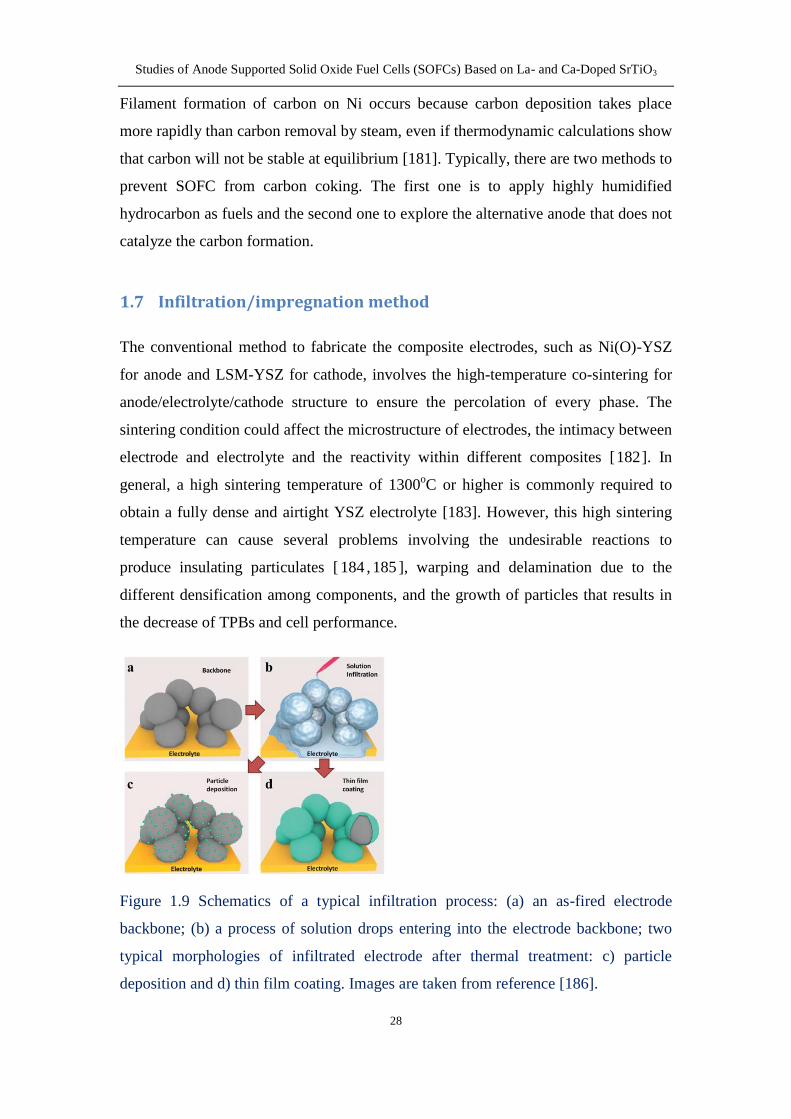
Figure 19 Schematics of a typical infiltration process (a) an as-fired electrode
backbone (b) a process of solution drops entering into the electrode backbone two
typical morphologies of infiltrated electrode after thermal treatment c) particle
deposition and d) thin film coating Images are taken from reference [186]
Studies of Anode Supported Solid Oxide Fuel Cells (SOFCs) Based on La- and Ca-Doped SrTiO3
29
In recent years infiltrationimpregnation methods have been widely employed in
fabrication of SOFC electrodes and found to be an effective way to solve a number of
problems induced by high-temperature sintering as mentioned above As illustrated in
Figure 19 a typical infiltration process involves the following three steps [186] 1)
preparation of porous electrode backbone (Figure 19(a)) which has been fired at
elevated temperature to ensure a good adhesion of electrode and electrolyte an
excellent connectivity for effective conduction of oxygen ions and electrons and good
structure stability under operation 2) infiltration of catalyst in the anode or electronic
conductors in the cathode (Figure 19(b)) A liquid solution which contains metal salt
precursors along with dispersant and surfactant is dropped into the pre-sintered
backbone 3) After thermal treatment two different morphologies of infiltrated
materials can be observed discrete particles and thin film coating as shown in Figure
19(c) and (d) respectively
The infiltration approach has shown many advantages when compared with the
conventional fabrication method First since the catalyst or conductive phase is
additive to the pores of the as-sintered scaffold it is much easier to fabricate an
engineered backbone with desirable structures using mature manufacturing and
processing techniques [186] This leads to the formation of the percolation of
conductive phase and offers a possibility to optimize the microstructure of the
electrode Second infiltration and subsequential low firing temperature enables easier
control of composition and particle sizes of catalyst [187] and avoids the formation of
undesirable secondary phase between the backbone and catalyst at high temperature
Third finely dispersed and nano-sized catalyst is more active than the composite
ceramics [188] because the structure of infiltrated composite is not random Finally
the large TEC of infiltrated composite such as NiONi or perovskite would not harm
the integrity of the whole cell
18 Objective of the work
In the present work an A-site deficient lanthanum- and calcium- co-doped strontium
titanate La02Sr025Ca045TiO3 (LSCTA-) which has been found to exhibit sufficient
electronic conductivity in fuel electrode environments excellent redox stability and
Studies of Anode Supported Solid Oxide Fuel Cells (SOFCs) Based on La- and Ca-Doped SrTiO3
30
promising performance [143189] is used as an anode support for button fuel cells In
order to improve the performance of LSCTA- anode precursors including Ni or Ni-Fe
bimetallic phases as well as CeO2 were impregnated into porous LSCTA- scaffolds to
improve the catalytic activity for the oxidation of hydrogen
In order to cater the development of intermediate temperature SOFCs results are
presented showing the fuel cell performance obtained on LSCTA- anode-supported
button fuel cells with thin electrolytes To investigate effects on the performance and
optimise this varied catalyst impregnated anodes are studied
The infiltration of metal oxides can be used to enhance the catalysis of perovskite
anode however the stability of impregnated nanoparticles in porous scaffold under
SOFC operating conditions is becoming a concern Most studies of stability testing
have been focused on cathode materials [59190191] suggesting that the degradation
can be attributed to the growth and densification of impregnated coatings on the
scaffold surface leading to the decrease in the effective electrochemical reaction sites
and therefore the significant reduction of performance Similarly for the titanate
perovskite anode a strong degradation was also observed and has been mainly
attributed to the increase of polarization resistance [192193] In this work we present
some stability studies on LSCTA- anode-supported fuel cells with Ni or Ni-Fe as well
as ceria infiltrated into the anode and try to understand the mechanism for the
degradation via the high-resolution scanning electron microscopy (SEM) on the cross-
section of the the ion beam etched samples The Focused Ion Beam (FIB) technique
was utilised for cross-section preparation to reveal the interface between the catalyst
and titanate because it is very difficult to distinguish the interaction between
impregnates and scaffolds on the surface morphology that occurs in the sub-micron
scale underneath the surface of the scaffold particles
In summary the main objective of this work is to study and develop a high-
performance anode via infiltrating nano-catalysts into pre-establishes LSCTA- anode
backbone for intermediate-temperature SOFCs High power density and reliability are
critical for SOFC application in the future So the targeted properties of the infiltrated
cells in our work are as follows (1) a current density reaches 10Acm2 for a cell
voltage equal to 07V at 800oC in humidified hydrogen (3 H2O) (2) a relatively
Studies of Anode Supported Solid Oxide Fuel Cells (SOFCs) Based on La- and Ca-Doped SrTiO3
31
stable stage under a given voltagecurrent density should be achieved in the operation
condition
The electroless nickel-ceramic co-depositon process was investigated as an alternative
manufacturing technique for the anodes of planar solid oxide fuel cells (SOFCs) The
effects of the added pore formers (starch) and surfactant (CTAB) in the plating
solution on the anode microstructure and electrochemical performance were discussed
in order to evaluate the practicability of electroless co-deposition technique for
preparation of the electrodes
Studies of Anode Supported Solid Oxide Fuel Cells (SOFCs) Based on La- and Ca-Doped SrTiO3
32
Chapter 2 Experimental techniques
21 Cell fabrication techniques
211 Tape casting
Tape casting is a well-established technique used for the mass production of large-
area ceramic substrates and multi-layered structures [194] This technique allows
fabrication of wide variety of controlled morphologies such as highly porous
electrodes and fully dense electrolytes [195~199] The method involves three steps
milling casting and drying as shown in Figure 21 The slurry preparation involves
two milling stages At the first stage the appropriate amount of ceramic powder and
pore formers are mixed and ball milled at a fast rate with addition of solvent and
dispersant This milling process is able to break the agglomerate particles and ensures
a properly dispersed ceramic in the mixture At the second stage binder plasticizer
and defoamer are added followed by ball-milling and de-airing process in order to
obtain the homogeneous and bubble-free slurry
Figure 21 Flow chart for the fabrication of a green tape
Stage 1 milling
Stage 2 milling
Tape casting
Drying
Slurry preparation
Ceramic powder
Solvent
Dispersant
Pore former
Binder
Plasticizer
Defoamer
Studies of Anode Supported Solid Oxide Fuel Cells (SOFCs) Based on La- and Ca-Doped SrTiO3
33
Figure 22 Schematic of the tape-casting set-up
The slurry is then cast on a MylarTM
carrier film upon a carrier moving at a controlled
speed Figure 22 illustrates the basic principles of the tape casting process The wet
thickness of the green tape is defined by the gap between the doctor blade and the
MylarTM
film which can be adjusted by the micrometer on the doctor blade The cast
tape is then kept in the drying chamber to allow the solvents to evaporate from the
surface leaving a dry tape on the carrier surface After drying the different green
tapes are cut into appropriate size and laminated into a multi-layer structure by
uniaxial pressing and passing through a hot laminator with the temperature around
80oC The laminated tapes then are placed on the zirconia plates and sintered at high
temperature typically above 1300oC
In order to reduce the required lamination steps in forming multi layer structures and
also increase the adhesion between different layers the slurry can be cast on the top of
a previously dried green tape with a different formulation namely a co-casting
process Typically the electrode slurry is cast on the dense electrolyte green tape after
drying [198~201]
Tape casting can be divided into two forms in terms of the selected solvent and the
subsequential additives non-aqueous (organic-based) tape casting and aqueous
(water-based) tape casting Organic-based solvents can ensure a dispersion of the
ceramic powder without hydration reaction and dissolution of organic components
Slurry
Green tape
Casting gapMylar paper
Carrier motion
Doctor blade
Studies of Anode Supported Solid Oxide Fuel Cells (SOFCs) Based on La- and Ca-Doped SrTiO3
34
Although the solvents are more volatile and irritating strong uniform green tapes are
easy to achieve [194] However the enormous environmental and safety concerns
associated with organic solvents such as toxicity volatility and inflammability have
stimulated interests in developing aqueous tape casting [202] It is difficult to obtain
flat fuel cells with thin gastight electrolytes using aqueous tape casting because of the
slow drying rate of the tape that causes the precipitation of different components high
crack sensitivity and poor wetting of the slip owing to the high surface tension of
water [197203] In this work crack-free and flat anode-supported fuel cells were
fabricated using aqueous (in Chapter 3) and non-aqueous (in Chapter 4) tape casting
techniques by adjusting the slurry formula and sintering profiles
212 Screen printing
Screen printing is another low-cost technique that has been widely used in
manufacturing the SOFC layers because of its efficient and reproducible manner The
quality of the printed layer is associated with the preparation of the ink The ceramic
powder with or without pore formers depending on the function of the formed layers
is first dispersed into acetone with a small amount of dispersant using rotary ball
milling After addition of vehicle the mixture is kept agitated until the acetone is
evaporated to yield the final ink
In this work the LSM-YSZ composite cathode was screen printed on the dense YSZ
electrolyte (in Chapter 7) LSMYSZ ink was prepared by weighting an exact amount
of YSZ and LSM powder (5050 in weight the total mass of powder was 10 grams)
and mixing with 02 gram of KD-1 dispersant in the plastic bottle 20 zirconia balls
with 1cm in diameter were also placed into the bottle Acetone was then poured into
the bottle until it covered all the powder and balls The bottle was placed on a roller
ball milling machine for 16h at a rotation speed of 160rpm This milling step could
increase the surface area of powder and improve the homogeneity of mixture After
ball milling the mixture was moved into a beaker The organic vehicle consisting of
5wt polyvinyl butyral (PVB) and 95wt terpineol was weighted out and poured
into the beaker The mass ratio of ceramic powder and vehicle was 3070 The beaker
was covered by a pierced parafilm and placed on a magnetic stirrer at room
temperature to evaporate the acetone slowly to form the LSM-YSZ ink
Studies of Anode Supported Solid Oxide Fuel Cells (SOFCs) Based on La- and Ca-Doped SrTiO3
35
Figure 23 The basic principle of screen printing process Images are taken from
reference [204]
Figure 23 illustrates the basic operating principle for the screen printing process At
the first step the screen made of an open weave mesh (in this case stainless steel) is
set up on the top of the substrate and fastened by the peripheral frames Meanwhile
the gap between the screen and substrate namely printing gap (generally 1-2mm) is
adjusted to ensure the contact of the mesh and substrate under a controlled pressure
from the squeegee during the printing stroke Then the prepared ink is put on the top
of the screen As the squeegee moves across the screen a downward pressure is
exerted which brings the mesh into contact with the substrate This downward force
along with the forward motion of the squeegee and the angle this makes with the
screen force the ink through the mesh and onto the substrate Behind the squeegee the
tension within the mesh will pull the mesh away from the substrate immediately
leaving the ink deposited on the substrate surface After every printing the sample
needs to be dried in an oven
In this work the screen printing process was carried out on DEK 248 semi-automatic
screen printer with an installed computer to control the printing program and ensure
the reproducible property of the printed layers The LSM-YSZ cathode ink was
Studies of Anode Supported Solid Oxide Fuel Cells (SOFCs) Based on La- and Ca-Doped SrTiO3
36
printed on dense YSZ electrolyte which has been sintered at 1350oC for 2h in air The
printing process need to be repeated for several times to obtain a desired thickness for
each cathode After each printing the sample was placed in an oven with a
temperature of 80oC to allow the printed coating fully dry Then the resulting sample
was firing at 1050oC for 1h in air with a heating and cooling ramp of 3
oCmin
213 Infiltrationimpregnation
Figure 24 Picture of metal nitrate solutions for wet impregnation in the (a) cathode
side and (b) anode side
The porous YSZ cathode and LSCTA- anode scaffolds have been fabricated by tape
casting and sintering approaches Although YSZ can provide the ionic conductivity
required for the cathode the lacking electronic conductivity and catalytic activity for
oxygen reduction would result in a poor performance limiting the SOFC application
Three kinds of aqueous solution were prepared by mixing the metal nitrates at an
exact ratio according to the formed compositions with critic acid and dissolving into
deionised water The precursor solutions used for impregnation containing
La08Sr02FeO3 (LSF) La08Sr02CoO3 (LSC) and La08Sr02Co02Fe08O3 (LSCF) were
made from La(NO3)2bull6H2O (Aldrich Chemistry 9999) Sr(NO3)2 (Aldrich ge99)
Co(NO3)2bull6H2O (Sigma-Aldrich ACS reagent ge98) and (Fe(NO3)3bull9H2O (Fisher
Scientific Analytical agent grade) as shown in Figure 24(a) Citric acid was also
added into the solution at a molar ratio of 11 for total metal ions citric acid and the
total concentration of metallic ions were 1molL The aqueous solution was placed on
the stirrer to accelerate the dissolution and dispersion process of nitrates The
impregnation approach was performed by dropping a small amount of solution on the
(a) (b)
Studies of Anode Supported Solid Oxide Fuel Cells (SOFCs) Based on La- and Ca-Doped SrTiO3
37
top of the porous electrode which diffused into the pores by a capillary force After
every impregnation the samples were placed in the furnace and fired at 450oC for 30
minutes to decompose nitrate Multiple cycles of impregnation and calcination at
450oC were used until the desired loading of impregnates of oxides was reached For
aqueous tape casted cells LSF and LSC were impregnated into the YSZ scaffold
successively to get a final loading of 15wt LSF and 5wt LSC (see section 32)
For organic tape casted cells 25wt LSCF were obtained after multi-impregnation
process and firing at 450oC (Chapter 4 and 5) The weight ratio of the impregnated
oxides is relative to the total weight of the YSZ cathode scaffold and the impregnated
oxides in this study
In order to increase the effective reaction sites and improve the electro-catalytic
activity in the anode Ni or Ni-Fe bimetal as well as ceria was introduced into the
anode scaffold by wet impregnation technique The nitrate precursor solutions
including CeO2 and Ni were prepared by dissolving Ce(NO3)36H2O (Sigma-Aldrich)
and Ni(NO3)26H2O (Newburyport MA USA) into deionised water respectively The
precursor solution containing Ni075Fe025 were made by mixing Ni(NO3)26H2O
(Newburyport MA USA) and Fe(NO3)3bull9H2O (Fisher Scientific Analytical agent
grade) at a molar ratio of 31 for Ni Fe in deionised water as shown in Figure 24(b)
Citric acid was subsequently added into the Ni-Fe nitrate solution at a molar ratio of
11 for total metal ions citric acid The total concentration of metallic ions were
1molL The solutions dropped onto the surface of porous LSCTA- anode would
diffuse along the pores into the LSCTA- scaffold by a capillary force The
impregnation steps were repeated to obtain a desired loading After each impregnation
the samples were fired at 450oC for 30 minutes to decompose the nitrate In our
experiment the final loadings of catalysts were 6wt CeO2 3wt Ni and 3wt Ni-
Fe bimetal The weight ratio of CeO2 or metal catalyst in the anode is relative to the
total weight of the LSCTA- anode scaffold and the impregnated catalysts in this study
Studies of Anode Supported Solid Oxide Fuel Cells (SOFCs) Based on La- and Ca-Doped SrTiO3
38
22 Material characterization
221 X-Ray Diffraction (XRD)
X-Ray Diffraction (XRD) is an analytical technique used for identifying the structure
of a crystalline material and determining the information of unit cell dimensions [205]
It can provide the reproducible patterns and does not destroy the sample itself
Figure 25 Illustration of Bragg diffraction
A crystal lattice can be considered as a unique arrangement of atoms in three
dimensions These atoms are arranged on a series of parallel planes and the spacing
between the adjacent planes is noted as d
When two parallel incident X-rays with identical wavelength λ approach interplanar
crystal atoms the X-ray reaching the top layer has less distance than the X-ray
reaching the lower layer Likewise the X-ray diffracted from the top layer has
travelled less distance than the X-ray scattered from the lower surface as illustrated in
Figure 25 The total distance can be noted as 2dsinθ depending on the interplanar
spacing d and the angle of incident rays θ When the distance is equal to a multiple
of the wavelength the reflected waves are in phase where the reflected rays with the
maximum intensity occur The equation can be expressed as
d
d
Incident X-rayDiffracted X-ray
θ
θ
θ
θ
dsinθ
Atomic-scale crystal lattice planes
Studies of Anode Supported Solid Oxide Fuel Cells (SOFCs) Based on La- and Ca-Doped SrTiO3
39
2 sind n (Equation 21)
where n is an integer The equation is known as Braggrsquos Law
X-ray diffraction (XRD) data on LSCTA- powder calcined at different temperatures
and reduced at 1000oC were obtained using a John PANalytical X-ray diffractometer
with CuKα1 radiation (λ = 154056Aring) in the range 2θ = 20-100o The XRD patterns
were analysed using the XrsquoPert HighScore Plus and STOE WinXPOW softwares to
determine the crystal structure and the lattice cell parameters The cell parameters
were also refined with Fullprof software
Figure 26 Schematic of metallic catalysts reduced at the simulated fuel cell operation
condition
The XRD experiments were also performed on Ni and Ni-Fe catalysts after the
different thermal treatments using a John PANalytical X-ray diffractometer with
CuKα1 radiation (λ = 154056Aring) in the range 2θ = 20-100o In order to identify the
phase of the impregnated materials Ni(NO3)26H2O and Fe(NO3)39H2O were
dissolved into deionised water to prepare nickel nitrate and nickel-iron nitrate
solutions at a molar ratio of 3 1 with addition of citric acid These solutions were
subsequently agitated and heated to 150oC for combustion followed by calcinations
in air at 450oC for 30 minutes as exactly the same as the impregnation of catalysts in
the anode A fraction of calcined powder was pressed into a pellet and suspended into
Counter electrode
ExhaustFuel (N2 H2 steam)
Air
Working electrode
Cathode
Ceramabond
YSZ electrolyte
Furnace
Anode
Silver Paste
Alumina tube
Suspended sampleAttached silver net
Studies of Anode Supported Solid Oxide Fuel Cells (SOFCs) Based on La- and Ca-Doped SrTiO3
40
an alumina tube which was sealed by a thick YSZ pellets with two silver wires
attached on the two electrodes The atmosphere in the tube can be controlled by the
flowing rates of the inserted water steam hydrogen and nitrogen and be monitored by
the OCV measurements on the silver electrodes with YSZ as electrolyte as shown in
Figure 26 By adjusting the flowing rates of gases (H2 N2 and steam) an OCV value
between 055-06V versus the ambient air at the cathode side at 700oC was obtained
where the powder was placed for 12h Under this voltage the oxygen partial pressure
in the chamber can be calculated around 10-13
atm Another fraction of the calcined
powder was reduced at 900oC for 12h in a 5 H2-Ar atmosphere The powders
calcined at 450oC in air and reduced at the oxygen partial pressure of 10
-13atm and 5
H2-Ar were characterized by XRD The relevant results are presented in section 435
and 436
222 Scanning Electron Microscopy (SEM) and Back-Scattered Electron (BSE)
Figure 27 Principle of SEM and BSE Images are taken from references [206207]
Studies of Anode Supported Solid Oxide Fuel Cells (SOFCs) Based on La- and Ca-Doped SrTiO3
41
Scanning Electron Microscopy (SEM) is a useful tool to reveal the microstructure of
materials at a range of microscale and nanoscale The focused electron beam emitted
by the electron gun travels through electromagnetic lenses which focus the beam
down toward the sample as shown in Figure 27 When the electron beam hits the
sample surface a series of signals are produced by the interaction between the
electrons and the sample including secondary electrons (electrons generated from the
sample itself) backscattered electrons (electrons resulted from the collision between
the electron beam and the nuclei of atoms in the samples) X-rays heat light and
transmitted electrons (beam electrons that pass through the sample)
The generated secondary electrons and back-scattered electrons can be detected by the
corresponding detectors producing the SEM and BSE images respectively SEM
image gives the information about the topography of the sample surface BSE can
provide the information about the chemical composition of different regions by
contrasting the brightness
In our experiment the morphology of LSCTA- powder calcined at the different
temperatures were analyzed by a JEOL model JSM 6700 Field emission gun (FEG)
scanning electron microscope (see section 313) SEM experiments were also
performed on the fractured cross section of Ni and CeO2+Ni impregnated anode
before and after the electrochemical testing at 700-800oC in humidified hydrogen (3
H2O) (see section 33)
BSE experiments were performed on the sintered tapes made from the LSCTA-
powder calcined at different temperatures plus varied weight percent of graphite (see
section 32) The pellets sintered at 1350oC were mounted in the epoxy resin ground
to 1200-grit sandpaper after drying and then polished on the polishing clothes with
diamond polishing paste of 1m The polished sample was fixed on the SEM holder
and coated with a thin layer of gold The lsquoImageJrsquo image analysis software was used
to evaluate the porosity of the porous anode scaffold on BSE images
In order to study the evolution of microstructure morphology and chemical
composition on the impregnated anodes upon the stability testing SEM and BSE
images were taken on the cross section of the samples using JSM 6700 scanning
Studies of Anode Supported Solid Oxide Fuel Cells (SOFCs) Based on La- and Ca-Doped SrTiO3
42
electron microscope and chemical elements were analyzed by an Oxford Inca Energy
Dispersive X-ray spectroscopy (EDX) equipped with JSM 6700 microscope The cells
after the stability testing in humidified hydrogen (3 H2O) at 700oC have been
polished by the Focused Ion Beam (FIB) to get a flat surface In order to obtain clear
and informative SEMBSE images the sample was mounted to the SEM specimen
holder using the carbon tape and then coated with a thin layer of gold prior to the
SEM measurements The SEM and BSE images were taken on the functional layer in
the LSCTA- anode near the anodeelectrolyte interfaces
223 Energy Dispersive X-ray (EDX) spectroscopy
Figure 28 Interaction volume of the different signals in the sample Image is taken
from reference [208]
Energy Dispersive X-ray (EDX) spectroscopy embedded in SEM is an analytical
technique used for the elemental analysis of a sample [ 209 ] It relies on the
characteristic X-rays generated in a sample by the interaction of the electron beam
and the sample The X-ray detector is used to absorb X-ray energy and convert into
voltage signal Then the signal is recorded as a spectrum with intensity versus X-ray
energy
The spatial resolution of EDX analysis in the SEM depends on the size of the
interaction volume which in turn is controlled by the accelerating voltage and the
Studies of Anode Supported Solid Oxide Fuel Cells (SOFCs) Based on La- and Ca-Doped SrTiO3
43
mean atomic number of the sample Z [210] In general the spatial resolution for
EDX is on the order of a few microns due to deep interaction volume by X-rays
penetrated into the sample as demonstrated in Figure 28 Compared with X-rays the
interaction volume of secondary electrons and backscattered electrons are much
smaller at the range of nanometers An accelerating voltage of 15-30kV is commonly
used to efficiently generate at least one family of X-ray lines for all elements
however high-energy primary electron beam could damage the sample or increase the
interaction volume The electron beam current (or spot size) is another parameter and
should be adjusted to minimize spectral artefacts and generate sufficient X-rays to
allow reliable quantification
224 Transmission Electron Microscopy (TEM)
Figure 29 Principle of TEM Image is taken from reference [211]
Transmission Electron Microscopy (TEM) is capable to not only provide more
detailed information of specimen microstructure than SEM but also show the
Electron Source
Electromagnetic lens system
Sample holder
Imagining system
Power cable
Magnetic lens
Vacuum Pipe
Air
Specimen
Projection lens
Imaging plate
Filament
Electron beam
Airlock
Studies of Anode Supported Solid Oxide Fuel Cells (SOFCs) Based on La- and Ca-Doped SrTiO3
44
information on element and compound structure on a molecular level Figure 29
shows the principle of a TEM The electron beam is emitted from the cathode made of
a tungsten filament when being heated and accelerated by the magnetic lens when it
travels towards to the sample The high-speed electron beam that passes through the
thin sample will travel down the column and project the enlarged image on the screen
after travelling through the projection lens
Because TEM samples should be beam transparent (usually le 100nm) the interaction
volume in the path of transmission electrons is much smaller than it would be in the
SEM [212] which has been illustrated in Figure 28 Therefore the spatial resolution
of EDX fitted within TEM is much better than that of EDX equipped within SEM
JEOL TEM 2011 transmission electron microscopy equipped with Oxford Isis EDS
detector was used to analyze the detailed microstructure and chemical composition of
the impregnated catalysts in the electrodes The TEM samples were prepared in the
following way at first the samples were fixed into Gatan G-1 epoxy to protect the
surface structures then the cured samples were cut and thinned to electro
transparency by mechanical grinding and focused ion beam polishing
225 Focused Ion Beam (FIB)
Figure 210 Principle of FIB
Ga+
e-
i+
no
e-
e-
e-
e-
e-
gas
Change Neutralisation (Optional)
Gas assisted etching or selective deposition (Optional)
Sample
Studies of Anode Supported Solid Oxide Fuel Cells (SOFCs) Based on La- and Ca-Doped SrTiO3
45
The focused ion beam (FIB) technique has been widely used for preparation of
electron microscopy specimens including semiconductors metals ceramics polymers
and biological materials [213] The FIB instrument setup is similar to a scanning
electron microscopy (SEM) except they rely on different beam sources an electron
beam for SEM and an ion beam for FIB [213214]
Gallium (Ga+) ions are usually used in FIB system due to its low melting point proper
weight and low volatility [215] The primary gallium ion beam approaches the sample
surface and sputters a small amount of material which leaves the surface as either
secondary ions (i+ or i
-) or neutral atoms (n
0) [216] as illustrated in Figure 210 The
primary beam also generates secondary electrons (e-) The signal from the sputtered
ions or secondary electrons can be collected to form an image
FIB technique allows to etch the sample surface at a range of nanoscale without
destruction of surface features and the underneath atoms In this work the
impregnated cells before and after the stability testing in humidified hydrogen (3
H2O) at 700oC were polished using Leica EM TIC 3X triple ion beam cutter system
The Leica EM TIC 3X equipment features three saddle field ion sources located in
one assembly They are perpendicular to the sample surface so the sample (mounted
on a holder) does not require an oscillating movement to reduce shadowingcurtaining
effects And three ion beams intersect at the centre edge of the mask forming a
milling sector of 100deg and allowing to cut the exposed sample (~20 to 100μm above
the mask) until the area of interest is reached [217] This unique triple ion beam setup
could reduce the processing time increase the milling depth and optimize the cross-
section quality Each gun allows to be controlled and switched separately which is
beneficial for a high quality milling
Studies of Anode Supported Solid Oxide Fuel Cells (SOFCs) Based on La- and Ca-Doped SrTiO3
46
Figure 211 Picture of the standard sample holder of the Leica EM TIC 3X instrument
used in this work Image is taken from reference [218]
Before ion milling the sample was treated by a mechanical process to get as close as
the area of interest and in order to decrease the milling time a final length of the
sample ready for etching was around 5mm Then the sample was pasted on the thin
aluminium plate (1times1cm2) using glue Then the plate was fixed onto the sample
holder using double-size copper adhesive tape After mounting the sample the sample
holder was placed between a sample stage and a mask as shown in Figure 211 The
sample surface is perpendicular to the mask The edge of the mask defines the surface
to be cut A manual high precision three axis stage allows accurate sample movement
in X Y and Z direction Sample can be viewed in all positions by using stereo
microscope equipped with the cutter system The stage permits a cutting position
accuracy of better than 10m All parameter settings for the milling process are
operated via a single touch screen control panel [218] The setting time used for
cutting a cross-section of one anode-supported fuel cell was approximately 8h when
using 3 guns under a voltage of 95kV and a current of 34mA
Studies of Anode Supported Solid Oxide Fuel Cells (SOFCs) Based on La- and Ca-Doped SrTiO3
47
226 Particle Size Analysis (PSA)
Figure 212 Principle of PSA using laser diffraction Image is taken from reference
[219]
Laser diffraction is a common and fully automated in-line method of measuring the
particle size distribution of a sample [219] As shown in Figure 212 when the light
emitted from the laser passes through a chamber with the particles in suspension it is
scattered by the particles and then detected by a series of detector array A particle
size distribution plot can be obtained by converting the intensity of scattered light
which is collected by the detectors using the mathematical algorithm
In this study particle size analysis of LSCTA- and YSZ powder was carried out on a
Malvern Instruments Mastersizer 2000 in deionised water as solution containing 2wt
hypermer KD6 (Croda Iberica SA) as dispersant To eliminate particle agglomeration
the tested powder was ball milled for 24 hours in deionised water using zirconia
grinding media (1cm in diameter) before the PSA measurement
227 BrunauerndashEmmettndashTeller (BET) measurement
The specific surface area (SSA) of a sample can be determined by physical adsorption
of a gas on the surface of a solid and by calculating the amount of adsorbate gas
corresponding to a monomolecular layer on the surface using a fully automated
Studies of Anode Supported Solid Oxide Fuel Cells (SOFCs) Based on La- and Ca-Doped SrTiO3
48
analyser [220] The process is usually conducted at the temperature of liquid nitrogen
The amount of gas absorbed can be measured by a volumetric or continuous flow
procedure BET measurements of LSCTA- powder calcined at varied temperatures
were obtained on a Micromeritics Tristar II 3020 instrument
228 Dilatometry
Figure 213 Principle of the dilatometer Image is taken from reference [221]
Dilatometry is a method used for determining the dimensional changes of the sample
versus temperature or time while the sample undergoes a controlled temperature
program [221] The measurement can be performed at different atmospheres such as
flowing air nitrogen or 5 H2-Ar
As shown in Figure 213 a pellet sample sandwiched by two alumina pellets (spacers)
is placed on the inside of sample carrier within a moveable furnace The pressure is
applied to the sample by pushrod which can transmit the length change to a linear
variable displacement transducer (LVDT) Then an output signal from LVDT is
recorded A thermocouple is placed next to the sample to measure the temperature In
order to eliminate the length change from the sample carrier the front part of the
Studies of Anode Supported Solid Oxide Fuel Cells (SOFCs) Based on La- and Ca-Doped SrTiO3
49
pushrod and the alumina spacers under the same temperature program as the sample
it is necessary to insert a correction curve conducted on an alumina pellet placed
between the two spacers into the sample measurement
The dilatometry measurement is used to analyze the sinterability of a green pellet and
the thermal expansion coefficient (TEC) of a sintered pellet The TEC can be
calculated by the following equation
0
1 L
L T
(Equation 22)
where α is the thermal expansion coefficient (TEC) L0 is the initial length of the
sintered sample ΔT and ΔL are the change in temperature and length respectively
The green pellets were prepared by pressing the powder with a uniaxial pressure of
either 110Mpa for LSCTA- or 150Mpa for 8mol yttria-stabilized zirconia (YSZ)
powder (HSY-8 DKK Japan) respectively in order to create porous LSCTA-
structure and dense YSZ structure as anode and electrolyte in the cell The final
pellets were 2mm thick and 13mm in diameter The temperature program for the
green pellets includes a heating ramp of 3oCmin from the room temperature to
1350oC a dwelling time for 3h and a cooling ramp of 3
oCmin from 1350
oC to room
temperature The flowing air was used for the sinterability experiments
The sintered pellets with different porosity were prepared by pressing the mixture
powder of LSCTA- and a varied amount of graphite and then firing at 1350oC for 2h in
air The dimension is around 2mm in thickness and 10mm in diameter The TEC
measurement was carried out in the flowing air and 5 H2-Ar atmospheres with a
heating ramp of 3oCmin from room temperature to 1000
oC
The dilatometry experiments were performed on a Netzsch DIL 402 C instrument
equipped with the Proteus thermal analysis software
Studies of Anode Supported Solid Oxide Fuel Cells (SOFCs) Based on La- and Ca-Doped SrTiO3
50
229 Thermal Gravimetric Analysis (TGA)
Figure 214 Principle of TGA Image is taken from reference [222]
Thermal gravimetric analysis (TGA) is an analytical technique used to measure
weight changes as a function of temperature andor time in a controlled atmosphere It
can provide information about physical phenomena such as second-order phase
transitions including vaporization absorption and desorption and chemical
phenomena including chemisorptions dehydration decomposition and solid-gas
reaction [223]
As shown in Figure 214 the sample is placed in the alumina crucible and rest on the
sample holder A thermocouple is placed next to the sample to measure the
temperature Under the temperature program the mass change of the sample is
measured by the microbalance system and recorded by the corresponding software It
allows to use different gaseous atmosphere such as air nitrogen 5 H2-Ar but it is
necessary to feed protective air (usually argon) to the system for the protection of the
microbalance system The TGA measurements in this work were carried out on a
Netzsch TG 209 instrument
Studies of Anode Supported Solid Oxide Fuel Cells (SOFCs) Based on La- and Ca-Doped SrTiO3
51
2210 Conductivity measurement
Figure 215 Four-probe setup for DC conductivity measurement
The conductivity of LSCTA- pellets was measured using four-probe setup instrument
as shown in Figure 215 where the two outer probes are connected to a DC current
source and the two inner probes are connected to a digital voltmeter As the current
passes between the outer probes the corresponding voltage across the inner probes
will be measured [224] The conductivity of the sample known as reciprocal of the
resistivity is related with the resistance (the ratio of the voltage to the output current)
and the geometrical characteristics of the sample For a rectangular solid the sample
conductivity σ can be given by
I S
V A (Equation 23)
where I and V are the current and voltage measured from the outer and inner probes
respectively S is the separation between the two inner probes and A is the cross-
sectional area of the sample
A
V
Direct Current Source
Ammeter
Digital Voltmeter
1 2 3 4
1 and 4 Current Probe
2 and 3 Voltage Probe
Studies of Anode Supported Solid Oxide Fuel Cells (SOFCs) Based on La- and Ca-Doped SrTiO3
52
In this work the conductivity measurement was carried out using four-probe system in
5 H2-Ar atmosphere as a function of temperature The samples were prepared by
tape casting technique using the same LSCTA- slurries for the anode green tapes and
sintering at 1350oC in air The slabs were 11times11mm in area and 05mm in thickness
Four platinum foil contacts were attached on the surface of the sample using platinum
paste and consolidated by firing at 900oC for 30 minutes
23 Electrochemical testing techniques
231 Two-electrode four-probe testing setup
Figure 216 Four-probe two-electrode setup used for the electrochemical testing of
anode-supported SOFCs
The single cell was mounted on an alumina tube using a four-probe two-electrode
setup as shown in Figure 216 Silver paste (ESL Europe) was used for the current
collection on the anode and cathode side and silver wire (Advent) as the lead for the
electrodes A single cell was sealed onto an alumina tube using ceramic adhesive
(Ceramabond 552 Aremco) which can separate the two atmospheres for the
electrodes and prevent the leakage problem A slow gas flow of Ar containing 5 H2
CE RE2
ExhaustFuel
Air
WE RE1
Anode
Alumina tube
Ceramabond
Electrolyte
FurnaceCathode
Silver Paste
Studies of Anode Supported Solid Oxide Fuel Cells (SOFCs) Based on La- and Ca-Doped SrTiO3
53
was fed into the anode chamber to avoid the oxidation of the anode upon heating to
testing temperature of 700800oC before switching to humidified hydrogen (3 H2O)
In this work humidified hydrogen (3vol H2O) was fed into the anode chamber as
the fuel at a flow rate of 30mlmin and ambient air was used as oxidant under cell
operation and stability testing The initial performance of CeO2-LSCTA- anodes
impregnated with and without metallic catalysts in humidified methane (3vol H2O)
were also evaluated at 700-800oC
232 Current-Voltage (I-V) measurement
Current-voltage (I-V) and current-power (I-P) curves are of importance for the
evaluation of the performance of the fuel cell An external circuit is connected to the
cell through the electrical lead wires attached on the electrodes I-V curves show the
relationship between the current flowing through the external circuit and the
corresponding voltage measured between the anode and cathode I-P curves are
defined as the power the product of the voltage and current as a function of the
current In general the current and power are divided by the active surface area noted
as current density (Acm2) and power density (Wcm
2)
When there is no current passing through the cell the electrical potential between the
cell can be measured by the voltmeter connected between the two electrodes which is
known as the open circuit voltage (OCV) The actual OCV value usually is slightly
lower than the theoretical OCV value predicted from the Nernst equation probably
due to the fuel crossover small internal currents or the slow reaction process With
the increasing current applied to the cell the potential is decreased due to the
polarization reactions occurring in the cell
The current-voltage curves were measured using a Solartron 1287 Electrochemical
Interface and CorrWare v32c software (Scribner Associates) with 4-lead
configuration as shown in Figure 216 The I-V measurements started at the OCV and
finished at -07V vs OCV The voltage was decreased at a rate of 25mVstep with
each step lasting 5s (see section 33) In section 43 and 53 the I-V curves were
scanned from OCV to -07V vs OCV then back to OCV at 25mVstep with single step
lasting 5s The I-V curves were measured in humidified pure hydrogen (3 H2O) at
Studies of Anode Supported Solid Oxide Fuel Cells (SOFCs) Based on La- and Ca-Doped SrTiO3
54
700-800oC under a cooling stage with a gas flowing rate of 30mLmin Moreover the
ceria and metal impregnated cells were also operated in humidified pure methane (3
H2O) and the I-V performances were recorded under a cooling stage from 800oC to
700oC with a gas flowing rate of 30mLmin (see section 53)
In this work the best performance of the cells with the same impregnated catalysts
was presented It should be noted that cell-to-cell performance variations at a given
composition were below 10 showing a good reproducibility
233 Electrochemical Impedance Spectroscopy (EIS)
2331 AC impedance
Electrochemical Impedance Spectroscopy (EIS) is a powerful tool for characterization
of electrochemical properties of a material and fuel cell system by isolating the
individual reactionmigration steps in multistep process Because each reaction or
migration step has a unique time constant associated with it these steps can be
separated in terms of the frequency domain [225] By applying a small sinusoidal
voltage perturbation to an equilibrium system the corresponding current can be
determined The impedance is defined as the ratio of the voltage perturbation to the
current response The impedance measurement is carried out over a broad range of
frequencies from several millihertz to several megahertz
When a weak amplitude signal V(w)=V0ejwt
under a single frequency f=w2π is
applied to the system a current of I(w)=I0ej(wt+φ)
can be measured V and I are out of
phase and frequency-dependent The complex resistance can be given by
(Equation 24)
Where j is the imaginary unit ( ) and φ is the phase angle shift
Therefore the total impedance Z the real part Re(Z) and the imaginary part Im(Z)
of the complex impedance can be written as
(Equation 25)
Studies of Anode Supported Solid Oxide Fuel Cells (SOFCs) Based on La- and Ca-Doped SrTiO3
55
(Equation 26)
(Equation 27)
Where |Z| is the magnitude of Z
Figure 217 The representative impedance graphs (a) Nyquist plot and (b) Bode plots
There are two ways to present the complex impedance graphically [226] Nyquist plot
with ndashIm(Z) as a function of Re(Z) and Bode plot with log|Z| or φ as a function of logf
as shown in Figure 217(a) and (b)
2332 Equivalent circuit
The EIS data describe a series of electrochemical behaviours of the studied system In
order to separate and understand the different contributions equivalent circuit is
proposed to fit with the impedance data The equivalent circuit consists of a number
of different electrical elements (such as resistor capacitor inductor constant phase
element (CPE) etc) in parallel in series or in combination of both The reasonable
explanation for the studied system depends on the selection of the electrical elements
and their interconnections
The commonly used elements in the equivalent circuit along with their impedances
and admittances are listed in Table 21 R is a resistor representing the conductive
pathways for electron and ion transport L is an inductor which is associated with
adsorptiondesorption processes at an electrode C is a capacitor which is associated
0 1000 2000 30000
-1000
-2000
-3000
Im( ) | | sinZ Z
Re( ) | | cosZ Z
-Im
(Z)
Re(Z)
2 2|Z|= Re( ) Im( )Z Z
1 10 100 1000 10000 10000010
100
1000
|Z|
0
-15
-30
-45
Frequency (Hz)
(a) (b)
Studies of Anode Supported Solid Oxide Fuel Cells (SOFCs) Based on La- and Ca-Doped SrTiO3
56
with the chargedischarge processes between the electrochemical double layers
Inductor and capacitor can be referred to space-charge polarization regions [227]
Besides the three ideal elements the constant phase element (CPE) and Warburg
element (W) have been found widespread use in the real system because the processes
occurring in the real system is not distributed in time and space ideally The
impedance behaviour of CPE depends on the exponent n (0 le n le 1) For a condition n
= 1 CPE becomes a pure capacitor C with for a case n = 0 CPE represents an
ideal resistor with In a real application of CPE n is determined from a
slope of a plot of logIm(Z) VS logf and defined between 0 and 1 When n = 05 CPE
describes the Warburg impedance for homogeneous semi-infinite diffusion [228]
Table 21 Impedances and admittances of the commonly used electrical elements [229]
Element Symbol Impedance Admittance
Resistor R R
Inductor L
Capacitor C
Constant Phase
Element (CPE) Q
Warburg element W
Studies of Anode Supported Solid Oxide Fuel Cells (SOFCs) Based on La- and Ca-Doped SrTiO3
57
Figure 218 (a) Nyquist diagram of impedance and (b) the corresponding equivalent
circuit of a typical fuel cell under OCV
Figure 218 shows EIS response and the corresponding equivalent circuit of a typical
fuel cell under OCV and operating condition The impedance graph in Figure 218(a)
is composed of two semicircles referred to as HF for high frequency and LF for low
frequency Two clearly separated arcs in the different frequency domains indicate that
the electrochemical reaction of the cell is controlled by two different electrode
polarization processes In general the HF arc is associated to charge transfer reaction
at the electrodeelectrolyte interfaces and TPBs [199] while the LF arc corresponds to
the gas diffusion reaction within the electrodes [230] The ohmic resistance of the cell
(Rs) determined from the high-frequency intercepts with the abscissa as shown in
Figure 218(a) primarily comes from the fuel cell electrolyte as well as electrical
resistance in the electrodes and lead wires To analyze the polarization resistance of
electrodes (Rp) which is represented by the distance between the high and low
frequency intercepts of the curve with the abscissa an equivalent circuit of
RΩ(R1Q1)(R2Q2) (Figure 218(b)) is used to fit the electrochemical impedance spectra
In the circuit RΩ is the ohmic resistance R1 and R2 are polarization resistance in HF
RΩ R1 R2
Q1 Q2
RΩ
(a)
(b)
Studies of Anode Supported Solid Oxide Fuel Cells (SOFCs) Based on La- and Ca-Doped SrTiO3
58
and LF domain and Q a constant phase element (CPE) relating to the nonohmic
processes in the electrodes The sum of R1 and R2 is considered to be the total
polarization resistance of electrodes (Rp)
In this study electrochemical impedance testing was carried out with two-electrode
configuration (shown in Figure 216) using a combination of Solartron 1255
Frequency Response Analyser Solartron 1287 Electrochemical Interface and ZPlot
v32c software (Scribner Associates) The frequency in the cell impedance testing
ranged between 1MHz and 004Hz and a sinusoidal voltage with the amplitude of
10mV was applied to the system as a perturbation signal The EIS testing results were
recorded at OCV condition Some of the impedance data were simulated using the
equivalent circuit by ZView 31 software (Scribner Associates) in this study (see
section 33)
2333 Studying the electrical properties of bulk using impedance
spectroscopy
Electrochemical Impedance Spectroscopy (EIS) has been extensively used to study
the electrochemical behaviour of materials and interfaces Besides the fact that it can
be used to analyze the different processes that occur in the whole fuel cell it also can
be used to describe the electrical properties of a bulk material for understanding the
conduction mechanism by separating the bulk and grain boundary resistance
Figure 219 Equivalent circuit of the impedance spectrum for a bulk electroceramic
two parallel RC elements in series
For a ceramic material bulk and grain boundary controlled processes can generally be
described by placing a resistor and a capacitor in parallel known as parallel RC
element In this case an equivalent circuit containing two parallel RC elements in
Rb
Cb
Rgb
Cgb
Studies of Anode Supported Solid Oxide Fuel Cells (SOFCs) Based on La- and Ca-Doped SrTiO3
59
series can represent the electrochemical phenomena of a ceramic sample bulk and
grain boundary transport respectively Figure 219 shows an equivalent circuit for
describing the electrical properties in a ceramic bulk For the individual parallel RC
element the relaxation time τ can be expressed by
1
summit
RC
(Equation 28)
Where summit represents the summit frequency of the semicircle that is descried by
the parallel RC element R and C are the bulk or grain boundary resistance and
capacitance respectively
Under an assumption that the studied ceramic behaves as a flat plane capacitor the
capacitance is strongly associated with its geometry Ad (A and d are the surface area
of one plate and the distance between two plates respectively) and its dielectric
constant εr The capacitance can be given by the following equation
0 r AC
d
(Equation 29)
Where 0 is the permittivity of vacuum 8854times10-12
Fm In a typical sintered sample
where Ad is expected to be 1-10 cm and the dielectric constant ~10 the bulk
capacitance can be calculated by the equation (29) in the order of 10-11
-10-12
F [231]
Studies of Anode Supported Solid Oxide Fuel Cells (SOFCs) Based on La- and Ca-Doped SrTiO3
60
Figure 220 A brickwork model for the sintered sample where db and dgb are the bulk
dimension and grain boundary thickness respectively
A brickwork model is used to describe an idealized ceramic sample as shown in
Figure 220 In this model a ceramic sample is comprised of cube-shaped grains with
bulk dimension (or grain size) db separated by a grain boundary with thickness dgb
Then the relationship of bulk capacitance Cb and grain boundary capacitance Cgb can
be obtained
gbb
gb b
dC
C d (Equation 210)
The subscripts b and gb stand for bulk and grain boundary respectively According to
this equation the well-sintered sample with narrow grain boundary thickness will
have a higher grain boundary capacitance It is found that a typical capacitance of
grain boundary is in the range of 10-11
-10-8
F [231]
Besides the bulk and grain boundary effects can be extracted from the impedance data
the electrode processes such as charge transfer adsorptiondesorption of
electrochemical species electrochemical reaction etc can be distinguished at the low
frequency with a higher capacitance [ 232] The capacitance associated with the
electrode processes lie in the range of 10-7
-100F
db
dgb
Studies of Anode Supported Solid Oxide Fuel Cells (SOFCs) Based on La- and Ca-Doped SrTiO3
61
In order to get better contact between the lead wire and the sample platinum paste
was applied on both the flat surfaces of the sintered LSCTA- pellet and then fired at
900oC for 30 minutes in air The AC impedance measurements were carried out using
the two-electrode configuration in the frequency range of 10MHz to 1Hz and the
temperature range of 290-675oC in air The impedance data were taken using a
Solartron 1260 impedancegain-phase analyzer A thermocouple was placed next to
the pellet to record the temperature The measured impedance data were then
analyzed by the Zview software and the values of capacitances and resistances were
extracted by fitting the experimental data with RC elements to segregate the
contribution of grain and grain boundary
Studies of Anode Supported Solid Oxide Fuel Cells (SOFCs) Based on La- and Ca-Doped SrTiO3
62
Chapter 3 Characterization of LSCTA- powder and its initial
performance for anode-supported SOFCs prepared by aqueous
tape casting
31 Characterization of LSCTA- powder
311 Analysis of X-ray Diffraction (XRD)
La02Sr025Ca045TiO3 (LSCTA-) powder was supplied by Topsoe Fuel Cells as part of
the EU FCH-JU project SCOTAS and was calcined at different temperature ranging
from 900oC to 1300
oC for 5h Figure 31 presents the X-ray diffraction (XRD) pattern
spectra of LSCTA- powder calcined at varied temperatures demonstrating that a pure
perovskite structure has obtained All the peaks were indexed to orthorhombic (Pbnm)
structure using WinXPOW software and identified by the corresponding miller
indices (h k l values) in Figure 31
Figure 31 X-ray diffraction (XRD) patterns of LSCTA- powders calcined at different
temperatures ranging from 900 to 1300oC for 5h
1300oC
1200oC
1100oC
1000oC
900oC
(211)
(202)
(240)
(206)
(044)(136)
20 30 40 50 60 70 80 90 100
Rela
tive inte
nsity (
arb
unit)
2 theta (deg)
(200)
(220)
(132)
(224)
Studies of Anode Supported Solid Oxide Fuel Cells (SOFCs) Based on La- and Ca-Doped SrTiO3
63
At room temperature A-site deficient La02Sr07TiO3 and La02Ca07TiO3 respectively
show cubic (Pm3m) [135] and orthorhombic (Pbnm) structure [ 233 ] With the
increasing Ca content La02Sr07-xCaxTiO3 system undergoes from cubic (Pm3m) for
x=0 to tetragonal (I4mcm) for x=01-04 to orthorhombic (Pbnm) for xge045 [189]
The symmetry of lanthanum strontium titanate has been decreased by the substitution
of smaller size Ca2+
(134Aring) for larger size Sr2+
(144Aring) due to the enhanced
distortion of perovskite structure by decreasing the tolerance factor [ 234 ] The
Goldschmidt tolerance factor (t) generally refers to defect-free perovskite and is a
dimensionless value associated with the structure stability which can be expressed as
2( )
A O
B O
r rt
r r
(Equation 31)
Where Ar Br and Or are the radii of the A cation B cation and oxygen anion
respectively Assuming that the A-site vacancies can be seen as the occupied sites
with the radius equivalent as zero the tolerance factor of cubic La02Sr07TiO3 is
calculated to be 0945 and it has been decreased to 0929 for orthorhombic LSCTA-
which is in good agreement with the transformation of the symmetry of the crystal
structure
Figure 32 X-ray diffraction (XRD) patterns of LSCTA- powder calcined at 1100oC for
5h before and after being reduced at 1000oC for 2h in 5 H2-Ar mixtures
after reduction
before reduction
20 40 60 80 100
Rela
tive inte
nsity (
arb
unit)
2 theta (deg)
Studies of Anode Supported Solid Oxide Fuel Cells (SOFCs) Based on La- and Ca-Doped SrTiO3
64
Table 31 The refined cell parameters and volumes in terms of the XRD patterns of
LSCTA- powder calcined at 1100oC for 5h before and after being reduced at 1000
oC
for 2h in 5 H2-Ar mixtures
Sample Space group a (Aring) b (Aring) c(Aring) Volume(Aring3)
Before reduction Pbnm 54681(8) 54670(3) 77329(5) 23117(4)
After reduction Pbnm 5473(9) 54671(8) 7733(3) 2314(4)
After reduction at 1000oC in 5 H2-Ar atmosphere the colour of the sample changes
from light yellow to black while the composition retaining its perovskite structure
and no extra peaks were observed (Figure 32) The refined cell parameters and
volumes for LSCTA- sample calcined at 1100oC without and with reduction are listed
in the table 31 showing an expansion of cell parameter after reduction especially the
value a The increase in the lattice parameter for the reduced sample is most likely due
to the formation of the higher volume of Ti3+
ions (ionic radius of 067Aring compared to
060Aring for Ti4+
CN=6) under reducing conditions however the formation of oxygen
vacancies by the removal of oxygen anions from the lattice could result in the decease
of the lattice parameter [235] So the combination of two contrary effects determines
the change of the lattice parameters The small variation in the lattice parameter
suggests that the compound has high stability against redox cycles during operation
The XRD of mixed LSCTA- and YSZ powder fired at 1400oC for 2h is shown in
Figure 33 along with XRD patterns of pure LSCTA- and YSZ as comparison No
evidence of impurity phases due to a chemical reaction is found It has been pointed
out in the previous study [236] that the chemical stability with YSZ is likely to be
improved by the introduction of A-site deficiency
Studies of Anode Supported Solid Oxide Fuel Cells (SOFCs) Based on La- and Ca-Doped SrTiO3
65
Figure 33 X-ray diffusion (XRD) patterns of mixture of LSCTA- and YSZ powders
fired at 1400oC for 2h (the upper one) LSCTA- powder calcined at 1100
oC for 5h (the
middle one) and 8YSZ (the bottom one) (PDF card No00-30-1468)
312 Particle Size Analysis (PSA) and Specific Surface Area (SSA)
Figure 34 Particle size distribution of LSCTA- powder after calcination at 900-1250oC
for 5h in air and ball milling for 24h
YSZ
LSCTA-
LSCTA-+YSZ
20 30 40 50 60 70 80 90 100
R
ela
tive in
tensi
ty (arb
unit)
2 theta (deg)
001 01 1 10 100 1000
0
2
4
6
8
10
900oC
1000oC
1100oC
1200oC
1250oC
vo
lum
e
particle diameter (m)
Studies of Anode Supported Solid Oxide Fuel Cells (SOFCs) Based on La- and Ca-Doped SrTiO3
66
Table 32 Mean particle size and specific surface area (SSA) of LSCTA- powder after
calcination at varied temperatures and ball milling
Calcination Temp (degC) d(05) (m) SSA (m2g
-1)
As-received powder - 3584
900 1542 962
1000 1781 617
1100 2198 214
1200 3774 066
1250 4212 047
The particle size of LSCTA- powder is an important parameter to the tape-casting
slurry in respects of dispersion homogeneity of ceramics particles viscosity of the
slurry the sintering behaviours of green tapes and the final structure Because the
calcination process is likely to cause the agglomeration of fine particles all the
powders for the particle size analysis have been ball milled for 24h in deionised water
with addition of dispersant in advance The PSA results of LSCTA- powders after
thermal treatment and ball milling are presented in Figure 34 A narrow and
unimodal distribution is observed for all the cases When calcination temperature is
increased from 900oC to 1250
oC the distribution shifts from the fine particles to
coarser particles
The mean particle size d(05) and specific surface area (SSA) of all samples are
presented in Table 32 The SSA of the as-received powder is 3584m2g
-1 much larger
than calcined powders indicating that it is composed of much smaller particles The
specific surface area (SSA) decreases with increasing calcination temperature
demonstrating a quick growth process of LSCTA- powder under calcination which is
in good agreement with the tendency of the mean particle size due to the inverse
relationship between particle size and surface area
Studies of Anode Supported Solid Oxide Fuel Cells (SOFCs) Based on La- and Ca-Doped SrTiO3
67
313 Scanning Electron Microscopy (SEM)
Figure 35 Scanning electron microscopy (SEM) images of LSCTA- powder after
calcination at (a) 900oC (b) 1000
oC (c) 1100
oC (d) 1200
oC (e) 1250
oC and (f)
1300oC
Scanning electron microscopy (SEM) analysis (Figure 35) of LSCTA- powders
calcined at different temperatures shows increasingly large grain size with the
increasing heating temperature The increase in the grain size of the powders is
(a)
(e)
(d)(c)
(b)
(f)
(g)
Studies of Anode Supported Solid Oxide Fuel Cells (SOFCs) Based on La- and Ca-Doped SrTiO3
68
induced by the agglomeration absorption and sintering of small grains due to
thermally activated diffusion process which has been introduced in the previous study
[237] It has been noted that the powder calcined at 900oC is comprised of fine and
isolated grains with average grain size of 100nm (Figure 35(a)) after calcinations at
1000 and 1100oC the necking between grains is formed with the average grain size
being hundreds of nanometres (Figure 35(b) and (c)) when the calcination
temperature is increased above 1200oC the powder shows apparent clusters and
agglomeration forming micro-sized particles
314 Dilatometry
Figure 36 (a) Sintering and (b) shrinkage rate curves for LSCTA- powders calcined at
different temperatures and YSZ powder as a function of temperature in air
0 300 600 900 1200 1500-04
-03
-02
-01
00
YSZ
900oC
1000oC
1100oC
1200oC
1250oC
Temperature (oC)
dL
Lo
(a)
0 200 400 600 800 1000 1200 1400-0010
-0008
-0006
-0004
-0002
0000
1237oC
1334oC
1329oC
1337oC
Temperature (oC)
YSZ
900oC
1000oC
1100oC
1200oC
1250oC
dLL
od
t (1
min
)
1276oC
1188oC
(b)
Studies of Anode Supported Solid Oxide Fuel Cells (SOFCs) Based on La- and Ca-Doped SrTiO3
69
In this study YSZ and LSCTA- powders are used for the electrolyte and anode
respectively Therefore the sinterability of LSCTA- and YSZ is very important to
avoid the defect of the cell in terms of delamination or cracks because of the stresses
between the electrolyte and anode originated from the mismatch of sintering process
Precalcination is used to tailor the commercial LSCTA- powder to match the
sinterability with the YSZ electrolyte in this study Because the sintering process of
ceramic powder at high temperature involves the vacancy diffusion on the surface and
through the grain boundary the precalcined powder is very effective in tuning the
properties of the ceramic for a porous support through high temperature sintering The
shrinkage extent and the onset sintering temperature are the main parameters to
determine the compatibility of two powders The dilatometer curves and the
corresponding shrinkage rate of calcined LSCTA- and YSZ powder in air are used to
scope the sinterability of the two powders as shown in Figure 36 Most of the
shrinkage occurred during the heating stages indicating the shrinkage process of the
heating stage is the main cause of the residual stresses produced in the cell YSZ
sample expands with increasing temperature up to around 1100oC because of the
thermal expansion and then shrinks abruptly to the maximum shrinkage rate at
1276oC (Figure 36(b)) followed by a lower shrinkage rate to 1350
oC revealing that
the sintering process approaches to the final stage The onset sintering temperature of
LSCTA- powder calcined below 1000oC is lower than that of YSZ and the total
shrinkage is much larger than YSZ reaching 345 and 329 for the powder
calcined at 900oC and 1000
oC respectively while the final shrinkage of YSZ powder
is only 249 The LSCTA- powders calcined below 1000oC seem to approach the
maximum shrinkage rate at lower temperature than YSZ The LSCTA- powder
precalcined at 1100oC shows a very similar sintering curve to the YSZ until the
temperature reaches 1276oC corresponding to the maximum shrinkage rate for YSZ a
continued fast sintering of the LSCTA- powder after this temperature causes the
mismatch of final shrinkage The LSCTA- powders calcined at 1200 and 1250oC
display a higher initiating temperature of densification and a smaller overall shrinkage
than those of YSZ which is in good agreement with the aforementioned BET analysis
results The temperature for the maximum shrinkage rate has been increased to 1334
and 1337oC for the powder calcined at 1200 and 1250
oC respectively The evident
Studies of Anode Supported Solid Oxide Fuel Cells (SOFCs) Based on La- and Ca-Doped SrTiO3
70
discrepancy of the temperature of the maximum shrinkage rate between LSCTA- and
YSZ may induce the local stresses between electrolyte and anode causing the crack
and delamination of the cell [238] The final shrinkage and temperature for the
maximum shrinkage rate are shown in Table 33
Table 33 Final shrinkage and temperature for the maximum shrinkage rate of LSCTA-
powder calcined at different temperatures from 900 to 1250oC along with YSZ as a
comparison
Powder Total shrinkage
()
Temperature for the maximum
shrinkage rate (oC)
YSZ 249 1276
LSCTA- 900oC 345 1188
LSCTA- 1000oC 329 1237
LSCTA- 1100oC 305 1329
LSCTA- 1200oC 238 1334
LSCTA- 1250oC 176 1337
Studies of Anode Supported Solid Oxide Fuel Cells (SOFCs) Based on La- and Ca-Doped SrTiO3
71
Figure 37 (a) Sintering and (b) shrinkage rate curves for mixed LSCTA- powder
calcined at 1100oC (10wt) and 1250
oC (90wt) compared with YSZ powder as a
function of sintering temperature in air
Based on the comparison of the dilatometric sintering results of LSCTA- powder
precalcined at different temperatures with YSZ powder it can be concluded that the
shrinkage behaviour of LSCTA- powder calcined at a certain temperature is not
compatible with the YSZ electrolyte The mismatch could cause the delamination or
cracks on the cell components during sintering resulting in the disfunction of the
whole cell In order to make a better match in both the overall shrinkage and
shrinkage rate with YSZ the mixed LSCTA- powder containing 10wt calcined at
0 200 400 600 800 1000 1200 1400
-03
-02
-01
00
dLL
o
Temperature (oC)
YSZ
LSCTA-
mixture
(a)
0 200 400 600 800 1000 1200 1400-0005
-0004
-0003
-0002
-0001
0000
0001
1311oC
1276oC
Temperature (oC)
dLL
od
t (1
min
)
YSZ
LSCTA-
mixture
(b)
Studies of Anode Supported Solid Oxide Fuel Cells (SOFCs) Based on La- and Ca-Doped SrTiO3
72
1100oC and 90wt calcined at 1250
oC was used The mixture shows a very similar
sintering shrinkage with YSZ 243 for the mixed LSCTA- pellet and 250 for YSZ
pellet (Figure 37(a)) It is important to notice that during 3h dwelling at 1350oC
LSCTA- green pellet shows a much larger shrinkage than YSZ (74 comparing with
23) so for co-sintering process the dwelling time is crucial to keep the YSZ and
LSCTA- bonded to each other The discrepancy of the temperature corresponding to
the maximum shrinkage rate between LSCTA- mixture and YSZ can be observable in
Figure 37(b) (1311oC for LSCTA- mixture and 1276
oC for YSZ) but the pores from
the graphite in LSCTA- green tape might alleviate the strain through the rearrangement
of LSCTA- powder
315 Thermal Expansion Coefficient (TEC)
The thermal compatibility between the anode materials and other fuel cell
components is crucial during fabrication or at thermal cycles during operation
According to the reported TEC values for dense and porous LST samples [154] the
porosity of anode could play an important role in affecting the TEC values The anode
material requires to present sufficient porosity in order to allow gas diffusion to the
triple phase boundary (TPB) for the electrochemical reaction so the relationship
between the anode porosity and thermal compatibility of anode and other fuel cell
components should be considered In general the porosity and the relative density of
a sample have an inverse relationship Therefore the prepared samples are
characterized by the corresponding relative densities
In this work the relative density r is expressed as a ratio of the experimental
density to the theoretical density
100er
t
(Equation 32)
Where e and t are the experimental and theoretical density respectively
The experimental density in gcm3 is calculated by the geometry of the sintered
samples which can be given by the following equation
Studies of Anode Supported Solid Oxide Fuel Cells (SOFCs) Based on La- and Ca-Doped SrTiO3
73
2
4e
mass mass
volume d l
(Equation 33)
Where l and d are the thickness and diameter of the sintered pellet in cm respectively
The theoretical density in gcm3 is calculated by using the cell parameters according
to the following equation
t
MZ
m MZN
V V NV
(Equation 34)
Where m and V are the mass and volume of the unit cell M is the formula weight of
the ceramic composition in gmol Z is the number of formula units in one unit cell N
is the Avogadro number known as 6022times1023
mol
Studies of Anode Supported Solid Oxide Fuel Cells (SOFCs) Based on La- and Ca-Doped SrTiO3
74
Figure 38 Thermal expansion curves for LSCTA- samples with different relative
density (47-92) sintered in air at 1350oC for 2h measured in (a) 5 H2-Ar
atmosphere and (b) flowing air
The thermal expansion behaviours of LSCTA- pellets sintered at 1350oC for 2h in
various atmospheres are plotted in Figure 38 and compared with the thermal
expansion of the YSZ electrolyte The thermal expansion coefficients (TEC) are
calculated and summarized in Table 34 The TEC values on both heating and cooling
stages for every sample are very reproducible so only the data on cooling are shown
above It is found that all the samples with varied relative density in reducing
atmosphere and air at the range of 100-1000oC present similar TEC values Therefore
in our cases the TEC values are not associated with the porosity (or relative density)
of the samples in two atmospheres There values are close to those of 11-12times10-6
K-1
(a)
(b)
100 200 300 400 500 600 700 800 900 1000 110000
03
06
09
12
15
dL
L0 (
)
Temperature (oC)
92
72
60
47
YSZ
Tested in 5 H2
100 200 300 400 500 600 700 800 900 1000 110000
05
10
15
20
92
72
60
47
YSZ
Tested in flowing air
dL
L0 (
)
Temperature (oC)
Studies of Anode Supported Solid Oxide Fuel Cells (SOFCs) Based on La- and Ca-Doped SrTiO3
75
in the temperature range 50-1000oC for LaxSr1-xTiO3+δ (x=01-04) samples [134] The
samples with relative density between 47 and 92 show lower thermal expansion
coefficient (TEC) values in air than those in reducing conditions but still slightly
higher than that of a typical zirconia based electrolyte The slightly higher TEC values
in reducing atmosphere than those in air could be attributed to the formation of Ti3+
ions in reducing atmosphere However the small difference of TEC values between
YSZ and porous LSCTA- may be a cause of possible fuel cell testing problems eg
spalling of YSZ from LSCTA- anode during operation or cracking upon thermal cycles
Table 34 Thermal expansion coefficients (TECs) for LSCTA- pellets with different
relative density (44-92) in various atmospheres from 100 to 1000oC
Atmosphere Relative density () TEC (times10-6
K-1
)
5 H2-Ar 92 120
72 127
60 121
47 120
Flowing air 92 116
72 115
60 116
47 118
8mol yttria-stabilized zirconia (YSZ) [88] 106-109
Studies of Anode Supported Solid Oxide Fuel Cells (SOFCs) Based on La- and Ca-Doped SrTiO3
76
316 Electrical conductivity
Figure 39 Electrical conductivity of LSCTA- sample with a relative density of 60 in
5 H2-Ar atmosphere as a function of temperature
It has been noted that the electrical conductivity of LST or YST depends to a very
large extent on the preparation and processing procedure leading to different porosity
and concentration of Ti3+
ions [235239] The desired electrical conductivity of anode
materials as a porous support is set to be greater than 1Scm [240] In dense form the
conductivity would need to be at least one order of magnitude greater The
conductivity of the LSCTA- sample with a high relative density around 91 has been
reported that after pre-reduction at 1050oC under 5 H2-Ar condition for 72h it could
be 30Scm [189] while a very slow reduction process at 880oC [234] implies that
high-temperature reduction may be required for LSCTA- anode support to maintain its
high electrical conductivity
Because the anode support requires to be sufficiently porous for the diffusion of fuel
the samples for conductivity measurement were prepared by the tape casting
technique and sintering at 1350oC in air for 2h the same as the fuel cell anode
fabrication The electrical conductivity of a porous LSCTA- sample with a relative
density of 60 was carried out in 5 H2-Ar atmosphere with the increasing
temperature to 900oC as shown in Figure 39 It was found that the conductivity
increase with temperature suggesting a semiconducting behaviour At 900oC the
300 400 500 600 700 800 90000
05
10
15
20
Temperature (oC)
(
Sc
m)
Studies of Anode Supported Solid Oxide Fuel Cells (SOFCs) Based on La- and Ca-Doped SrTiO3
77
conductivity can reach 17Scm due to the reduction of Ti4+
to Ti3+
which is sufficient
to provide electrical pathways for SOFC anodes However at the operation
temperature of 700oC the conductivity is only 025Scm indicating a high ohmic
resistance could be caused by the low conductivity of the anode leading to the
inferior performance for example for an anode support with thickness of 05mm an
ohmic loss of 02Ωcm2 could be obtained for the anode
Figure 310 Temperature dependence of the electrical conductivity of a pre-reduced
LSCTA- sample with a relative density of 60 in 5 H2-Ar atmosphere on cooling
stage
In order to investigate the influence of the pre-reduction condition on the conductivity
a porous sample with a relative density of 60 was sintered at 1350oC in air followed
by pre-reduction at 1000oC for 24h in tube furnace under a constant purge flow of 5
H2-Ar before conductivity measurement To avoid the re-oxidation of the pre-reduced
sample 5 H2 was fed into the jig with the sample in place for one hour to flush
away the residue air before increasing the temperature for measurement The
temperature dependence of the electrical conductivity in reducing atmosphere is
shown in Figure 310 The measurement was carried out upon cooling from 800oC to
room temperature after being kept at 800oC for 24h under PO2lt10
-22atm in 5 H2-Ar
atmosphere The conductivity increases with the decreasing temperature until 300oC
and below this temperature the conductivity decreases with the decrease of the
0 100 200 300 400 500 600 700 8002
3
4
5
6
7
8
(
Sc
m)
Temperature (oC)
Cooling
Studies of Anode Supported Solid Oxide Fuel Cells (SOFCs) Based on La- and Ca-Doped SrTiO3
78
temperature showing a metalndashsemiconductor transition from high temperature to
room temperature At 700oC a conductivity of 59Scm is obtained for a porous
sample which is quite promising for the electronic transport as an anode support
However the conductivity value is much lower than the one reported for porous
La04Sr04TiO3 samples probably due to more A-site vacancies and substitution of
La3+
for Sr2+
and higher reducing temperature up to 1100-1300oC [235] leading to the
massive formation of Ti3+
ions
According to the conductivity measurement LSCTA- is a good candidate as anode
material for intermediate temperature SOFCs after pre-reduction at high temperature
around 1000oC However careful consideration should be made when impregnating
catalyst into the electrodes to prevent the re-oxidation of reduced anode during
thermal treatment of the catalyst precursors
32 Cell fabrication
Figure 311 Process for the fabrication of LSCTA- anode-supported fuel cells
In this chapter the button fuel cells were fabricated by an aqueous tape casting and
co-casting technique with co-sintering of dense YSZ electrolytes bonded to porous
skeletal electrodes (LSCTA- and YSZ) The resulting cells then were pre-reduced in
reducing atmosphere followed by multi-infiltration of catalyst or ionicelectronic
conductors in the electrodes as illustrated in Figure 311
The slurry formulation is the most crucial step for tape casting the green tapes and
hence the sintered samples The general procedure is as follows In the first step the
ceramic powder (LSCTA- for anode and YSZ for cathode) and flake graphite (Alfa
LSCTA-+pore formers
Electrolyte
Cathode
Anode
YSZ+pore formers
Cocast YSZ and
LSCTA-
SinteringTape
Lamination
Porous LSCTA-
1350 oC
Infiltration and firing
Porous YSZ
Pre-reduction 950-1000 oC
Dense YSZ
450 oC
Studies of Anode Supported Solid Oxide Fuel Cells (SOFCs) Based on La- and Ca-Doped SrTiO3
79
Aesar) were mixed and ball milled at a fast rate for 24h with addition of de-ionised
water as solvent and hypermer KD6 (Croda Iberica SA) as dispersant In the second
step another 24-h ball-milling was carried out after Poly(ethylene glycol) (PEG
Sigma-Aldrich) and Glycerol (Fisher Scientific UK Limited) as plasticizer Polyvinyl
alcohol (PVA Alfa Aesar) as binder and containing Ethoxylated 2 4 7 9-Tetraethyl
5 Decyn-4 7-diol (Haikutech Europe BV) as defoamer were added to the
homogenized powders successively Then the mixed suspension was de-aired by
slow ball milling and cast onto a Mylar film to produce a ceramic green tape
321 LSCTA- tapes made from the powder calcined at single temperature
Figure 312 Back-scattered electron (BSE) images of anode from LSCTA- powder (a)
calcined at 1100oC with addition of 120wt graphite (b) calcined at 1200
oC with
addition of 70wt graphite and (c) calcined at 1250oC with addition of 35wt
graphite The weight percentage of graphite is relative to the mass of the LSCTA-
ceramic powder used in the slurry The laminated tapes shown above were sintered at
1350oC in air for 2h
Dense YSZ
Porous LSCTA-
Delaminationbetween YSZLSCTA-
(a)
(b) (c)
Porous LSCTA-
Porous LSCTA-
Dense YSZ
Dense YSZCrack on YSZCrack and delamination
Studies of Anode Supported Solid Oxide Fuel Cells (SOFCs) Based on La- and Ca-Doped SrTiO3
80
The BSE images of the sintered tapes made from LSCTA- powder calcined at different
temperatures for 5h with varied weight ratios of graphite are shown in Figure 312 A
porosity of 58 can be obtained on the LSCTA- anode after sintering at 1350oC for 2h
when 120wt graphite was added into the slurry consisting of LSCTA- powder
calcined at 1100oC while delamination between YSZ and LSCTA- layers occurred
due to the mismatched sintering process of two materials (see section 314) The total
shrinkage of YSZ around 25 after firing at 1350oC is much smaller than LSCTA-
powder calcined at 1100oC Under this effect a warped and detached YSZ electrolyte
on the LSCTA- anode was formed after high-temperature sintering as shown in Figure
312(a)
A porosity of 60 was observed from the mixed slurry of LSCTA- powder calcined at
1200oC for 5h with 70wt graphite shown in Figure 312(b) It can be seen that the
dense YSZ electrolyte was broken mainly because of the different shrinkage onset
temperature in the early sintering stage The dilatometry measurement of LSCTA-
powder calcined at 1200oC shows an onset of densification at around 1200
oC higher
than 1100oC of YSZ powder When the sintering temperature reaches at 1100
oC YSZ
green tapes begin to shrink while LSCTA- powder calcined at 1200oC remains
unchangeable resulting in crack on the YSZ surface especially on the edge Moreover
a larger shrinkage of YSZ than LSCTA- towards the sintering process could accelerate
the formation of crack on the thin YSZ layer
The anode prepared by the LSCTA- powder thermally treated at 1250oC plus 35wt
graphite as pore former is presented in Figure 312(c) where the porosity of 45 was
anticipated As discussed in the dilatometry measurements because YSZ has a lower
shrinkage onset temperature than LSCTA- powder calcined at 1250oC when the
sintering temperature reached 1100oC the shrinkage stress produced in the thin YSZ
electrolyte could result in the fragmentation of YSZ layer Furthermore the
mismatched shrinkage between YSZ and LSCTA- could deteriorate the adherence of
the thin YSZ layer on LSCTA- anode The porosity of the anodes fabricated from
LSCTA- powder calcined at different temperatures with an addition of various
proportions of graphite is listed in Table 35 It is noted that the formed porosity is not
Studies of Anode Supported Solid Oxide Fuel Cells (SOFCs) Based on La- and Ca-Doped SrTiO3
81
only relevant to the amount of graphite but also related with the grain size of the
LSCTA- powder used in slurry
Table 35 The porosity of the LSCTA- anode made from the powder calcined at
different temperatures (1100 1200 and 1250oC) with an addition of graphite (The
density of LSCTA- was calculated using the cell parameters Average density of
graphite is 215gcm3)
Calcined
Temperature (oC)
Graphite
(wt )
Graphite
(vol )
Porosity () from
ImageJ
1100 120 277 58
1200 70 162 60
1250 35 81 45
relative to massvolume of LSCTA- powder
Studies of Anode Supported Solid Oxide Fuel Cells (SOFCs) Based on La- and Ca-Doped SrTiO3
82
322 LSCTA- tapes made from the mixed powder calcined at two
temperatures
Figure 313 Back-scattered electron (BSE) images of anode from LSCTA- powder (a)
calcined at 1100oC (20wt) and 1250
oC (80wt) with 40wt graphite (b)
calcined at 1100oC (15wt) and 1250
oC (85wt) with 40wt graphite and (c)
calcined at 1100oC (10wt) and 1250
oC (90wt) with 30wt graphite The weight
percentage of graphite is relative to the mass of the LSCTA- ceramic powder used in
the slurry The laminated tapes shown above were sintered at 1350oC in air for 2h
The picture of half cell made from LSCTA- powder calcined at 1100oC (20wt) and
1250oC (80wt) plus 40wt graphite in the inset of Figure 313(a) reveals the
formation of the wrinkles on the edge of YSZ surface The BSE image of the cross
section on the edge of the sample is shown in Figure 313 (a) demonstrating a good
connectivity between YSZ and LSCTA- but coupled with the crack and arch formed
on the YSZ electrolyte The optimized half cell using LSCTA- powder calcined at
1100oC (15wt) and 1250
oC (85wt) with an addition of 40wt graphite is
2cm(a)
(b) (c)
YSZ electrolyte
LSCTA- anode
Studies of Anode Supported Solid Oxide Fuel Cells (SOFCs) Based on La- and Ca-Doped SrTiO3
83
presented in Figure 313(b) Compared with the former sample the latter sample has a
longer wrinkle on the edge of YSZ surface but the arch of YSZ layer is less evident
When 30wt graphite was added into the LSCTA- powder calcined at 1100oC
(10wt) and 1250oC (90wt) and an alumina plate was applied on the top of the
green tapes during sintering a high-quality cell was obtained The BSE image in
Figure 313(c) shows a good adherence of the different layers
Therefore the anode material we used in the slurry is the mixture of 10wt LSCTA-
calcined at 1100oC and 90wt LSCTA- calcined at 1250
oC in respects of the matched
dilatometric curves with YSZ electrolyte upon sintering The dense YSZ green tapes
were fabricated using the same chemicals without pore former To maximize the
bonding of LSCTA- anode and YSZ electrolyte co-casting of LSCTA- and YSZ green
tapes was employed where the mixed suspension of LSCTA- was cast on the top of
the thin YSZ green slip The recipes of YSZ and LSCTA- tapes used in our
experiments are summarized in Table 36 and Table 37
Table 36 Recipes of denseporous YSZ tapes using aqueous tape casting technique
Stage Ingredients Dense YSZ tape (g) Porous YSZ tape (g)
Stage 1
milling
YSZ 20 20
Graphite - 123
Deionised water 12 18
Hypermer KD6 028 042
Stage 2
milling
PEG 12 20
Glycerol 24 40
PVAa 12 20
Defoamer 028 042
a 15wt PVA dissolved in deionised water
Studies of Anode Supported Solid Oxide Fuel Cells (SOFCs) Based on La- and Ca-Doped SrTiO3
84
Table 37 Recipes of co-castsupported LSCTA- tapes using aqueous tape casting
Stage Ingredients Co-cast LSCTA- layer (g) LSCTA- support (g)
Stage 1
milling
LSCTA- (1100oC) 15 25
LSCTA- (1250oC) 135 225
Graphite 45 60
Deionised water 14 23
Hypermer KD6 032 048
Stage 2
milling
PEG 15 23
Glycerol 30 46
PVAa 14 21
Defoamer 032 048
a 15wt PVA dissolved in deionised water
Figure 314 TGA curve for the porous YSZ tape at a heating ramp of 3oCmin
0 200 400 600 800 100030
40
50
60
70
80
90
100
Temperature (oC)
TG
(
) combustion
of organics
combustion
of graphite
Studies of Anode Supported Solid Oxide Fuel Cells (SOFCs) Based on La- and Ca-Doped SrTiO3
85
Figure 315 Temperature program for co-sintering of the green tapes
After drying overnight at room temperature the green tapes were cut to an appropriate
size and laminated followed by co-sintering at 1350oC for 2h in air The sintering
program is crucial for the formation of a defect-free ceramic cell and can be
determined by the TGA of the porous YSZ tape with temperature at a heating ramp of
3oCmin as shown in Figure 314 The mass of the tape starts to decrease at 120
oC
when the organic chemicals added to the tape as plasticizer and binder begins to burn
out This process is required to be gentle to avoid a rapid increase of gas pressure
otherwise it can cause damage to the cell such as deformation crack and stresses
The mass reduction above 600oC can be attributed to the combustion of graphite
In terms of temperature dependence of TGA the sintering program is settled and
shown in Figure 315 In order to avoid the formation of the defects resulting from the
combustion of organics and graphite a slow ramping rate of 1oCmin up to 750
oC was
used Then a dwelling stage of 2h at 750oC was followed to burn off graphite and
organic residues completely The temperature was raised to 1350oC at a faster ramp
rate of 3oCmin and kept for 2h to allow the final shrinkage and produce a fully dense
electrolyte At the cooling stage the temperature was cooled down to room
temperature at a ramp rate of 35oCmin The sintered samples of 2cm in diameter
were subjected to a reduction process at 1000oC for 12h in a 5 H2-Ar atmosphere
Upon reduction the colour of LSCTA- changes from light yellow to black
0 3 6 9 12 15 18 21 24 270
300
600
900
1200
15002h
Cooling 35oCmin
Heating 3oCmin
Te
me
ratu
reo
C
Timeh
Heating 1oCmin
2h
Studies of Anode Supported Solid Oxide Fuel Cells (SOFCs) Based on La- and Ca-Doped SrTiO3
86
The cathode side of pre-reduced samples was impregnated with precursor solutions
containing La08Sr02FeO3 (LSF) and La08Sr02CoO3 (LSC) successively and fired at
450oC in air to decompose nitrate while avoid the re-oxidation of LSCTA- The
loadings of impregnates into the YSZ cathode scaffold were 15wt LSF and 5wt
LSC Anode catalyst materials including CeO2 and Ni were impregnated into the
porous LSCTA- anode scaffold using solutions from Ce(NO3)36H2O and
Ni(NO3)26H2O Multiple cycles of impregnation and calcination at 450oC were used
until the desired loading of impregnates of oxides was reached Figure 316 shows the
BSE image of the cross-section of LSCTA- anodeYSZ electrolyte interface after the
impregnation of ceria and nickel in the anode side and the firing process It can be
seen that the impregnated catalysts have successfully diffused into the interfacial area
across the thick anode support
Figure 316 (a) Back-scattered electron (BSE) image of the cross section of the
LSCTA- anodeYSZ electrolyte after impregnation of CeO2+Ni and firing
LSCTA-
CeO2+Ni
YSZ electrolyte
Studies of Anode Supported Solid Oxide Fuel Cells (SOFCs) Based on La- and Ca-Doped SrTiO3
87
33 Performance of LSCTA- anode-supported cells
331 Microstructure of the cells
Figure 317 (a) Back-scattered electron (BSE) image of the cross section of anode-
supported cell produced by aqueous tape casting (from left to right porous LSCTA-
anode dense YSZ electrolyte and porous YSZ cathode) scanning electron
micrographs (SEM) images of (b) porous LSCTA- anode backbone and (c) porous
YSZ cathode backbone prior to impregnation
(a)
(c)
(b)
Studies of Anode Supported Solid Oxide Fuel Cells (SOFCs) Based on La- and Ca-Doped SrTiO3
88
A BSE micrograph of the cross-section of the anode-supported button cells produced
by aqueous tape casting is presented in Figure 317(a) showing the dense YSZ
electrolyte adhering well with two porous electrode skeletons In this study the cells
consisted of a 40m thick dense YSZ disk sandwiched by an 85m thick porous YSZ
layer on one side and a 450m thick porous LSCTA- layer on the other side A crack-
free dense YSZ electrolyte has been successfully obtained on the LSCTA- anode
substrate after co-sintering technique without open pores As shown in the magnified
SEM image of the fractured LSCTA- layer before impregnation (Figure 317(b)) the
necks between the LSCTA- particles are difficult to distinguish indicating that a well-
sintered scaffold has formed possibly due to the addition of fine particles from
LSCTA- powder calcined at 1100oC The porous YSZ layer in Figure 317(c) shows a
much smaller homogeneous particle size of 1m surrounded by the random pores
between 1 and 5m in size The coarse pores formed in the porous electrodes are
caused by the burnout of pore formers which favours the easy transport of gas even
after impregnation The flake-like pores are attributed to the shape of graphite that is
pore-forming agent in the porous tapes
Studies of Anode Supported Solid Oxide Fuel Cells (SOFCs) Based on La- and Ca-Doped SrTiO3
89
332 Electrochemical testing
Figure 318 (a) I-V and power density curves and (b) impedance spectra for single-
phase LSCTA- anode-supported cell in humidified hydrogen as a fuel gas and air as an
oxidant gas collected at the following temperatures upon cooling 700 750 and 800oC
The impedance spectra were measured at open circuit voltage (OCV) Symbol and
line in (b) represent the experimental data and fitting data using the equivalent circuit
respectively (c) Equivalent circuit of the impedance spectra in this study
000 005 010 015 020 025 030 035
04
06
08
10
12
700oC
750oC
800oC
EV
IAcm-2
000
003
006
009
012
015
PW
cm
-2
0 1 2 3 4 50
-1
-2
-3
-4
-5
01Hz 01Hz
008Hz
Z
cm
2
Zcm2
700 oC
750 oC
800 oC
RΩ R1 R2 R3
Q1 Q2 Q3
(a)
(b)
(c)
Studies of Anode Supported Solid Oxide Fuel Cells (SOFCs) Based on La- and Ca-Doped SrTiO3
90
The fuel cell was directly mounted and sealed onto an alumina tube and a gas flow of
Ar containing 5 H2 was fed into the anode chamber to avoid the oxidation of the
anode upon heating to testing temperature 800oC before switching to humidified
hydrogen (3vol H2O) The LSCTA- anode-supported button fuel cells (LSCTA-
YSZLSF-LSC-YSZ) with an active area of 08cm2 were electrochemically
characterized at 700-800oC using humidified H2 (3vol H2O) as fuel and ambient air
as oxidant The data were collected upon cooling down from 800 to 700oC In Figure
318(a) the open circuit voltages (OCVs) recorded are 109 108 and 107V at 700
750 and 800oC respectively which is close to the theoretical values calculated from
the Nernst equation The high OCV values indicate that the thin electrolyte is
sufficiently dense and the cell is well sealed onto the testing jig The initial Area
Specific Resistance (ASR) values calculated as the slope of the I-V curves are 63 32
and 24Ωcm2 at 700 750 and 800
oC respectively The maximum power densities
(Figure 318(a)) for the cell without catalysts on the anode side are 50 94 and
124mWcm-2
at 700 750 and 800oC respectively In order to understand the factors
limiting cell performance the electrochemical impedance spectra measured at OCV
from 700 to 800oC are presented in Figure 318(b) The ohmic resistances of the cell
(Rs) determined from the high-frequency intercepts with the abscissa range from
055Ωcm2 at 700
oC to 025Ωcm
2 at 800
oC According to the conductivity of YSZ in
the literature [41] the contribution of the 40-m thick YSZ electrolyte to the ohmic
resistance is around 020Ωcm2 at 700
oC and 010Ωcm
2 at 800
oC The measured ohmic
losses are much larger than the calculated values of YSZ electrolyte because they
also include the ohmic resistance of electrodes and current collection of silver paste
and electrodeelectrolyte interfacial resistance The low contribution of ohmic losses
from the electrodes demonstrates that LSCTA- backbone has a reasonable electronic
conductivity The cell losses are dominated by the polarization resistance of
electrodes (Rp) which are represented by the distance between the high and low
frequency intercepts of the curve with the abscissa In order to analyze the nonohmic
losses an equivalent circuit of RΩ(R1Q1)(R2Q2)(R3Q3) (in Figure 318(c)) was used to
fit the impedance spectra where R is a resistance and Q a constant phase element
(CPE) The fitting results reveal three distinct electrode processes corresponding to
the high-frequency (~3kHz) medium-frequency (~5Hz) and low-frequency
frequency (~01Hz) arcs The sum of R1 R2 and R3 is considered to be the total
Studies of Anode Supported Solid Oxide Fuel Cells (SOFCs) Based on La- and Ca-Doped SrTiO3
91
polarization resistance of electrodes (Rp) The fitted impedance parameters are listed
in Table 38
Table 38 The fitting parameters (Ωcm2) for Impedance Spectra of the LSCTA-
backbone cell tested at different temperatures in humidified hydrogen (3vol H2O)
Resistance 700oC 750
oC 800
oC
R1 052 011 0036
R2 120 092 070
R3 398 150 112
Rp 570 253 186
The primary non-ohmic resistance is attributed to the low-frequency response with
summit frequency value of ~01Hz The appearance of thermally activated low-
frequency arc may suggest that the dissociative adsorption of gaseous species and
surface diffusion are the arc-related processes The high- and medium-frequency arcs
are probably related with the charge transfer (oxygen ions and electron) between bulk
and surface of the electrodes However it is difficult to separate the losses from the
anode and cathode The Rp values simulated from the equivalent circuit
(Rp=R1+R2+R3) range from 570Ωcm2 at 700
oC to 186Ωcm
2 at 800
oC demonstrating
a poor electrocatalytic activity of the LSCTA- backbone for hydrogen oxidation
because the non-ohmic losses of the cathode are estimated to be around 013Ωcm2 at
700oC [59] It is noteworthy that the polarization resistance values were much smaller
than those of electrolyte-supported cell with LSCTA- backbone anode at 900oC
(45Ωcm2) [143] and LST single-phase anode at 800
oC (96Ωcm
2) [172] and cathode-
supported cell with mixed YST and YSZ as anode at 800oC (29Ωcm
2) [158] For the
first two cells the polarization resistance from the screen printed LSM-YSZ
composite cathode could be negligible around 05-08Ωcm2 at 800-950
oC [241] The
improved Rp values can be explained by the generated oxygen vacancies with the
formation of Ti3+
upon high-temperature reduction therefore increasing the reaction
Studies of Anode Supported Solid Oxide Fuel Cells (SOFCs) Based on La- and Ca-Doped SrTiO3
92
sites and improving the performance when using LSCTA- scaffold as the ionic and
electronic conductive channel
Figure 319 (a) I-V and power density curves and (b) impedance spectra for 3wt Ni
impregnated LSCTA- anode-supported cell in humidified hydrogen as a fuel gas and
air as an oxidant gas collected at the following temperatures upon cooling 700 750
and 800oC The impedance spectra were measured at open circuit voltage (OCV)
Symbol and line in (b) represent the experimental data and fitting data using the
equivalent circuit respectively
(a)
(b)
00 02 04 06 08 1000
02
04
06
08
10
12
700oC
750oC
800oC
EV
IAcm-2
00
01
02
03
04
PW
cm
-2
00 03 06 09 12 1500
-03
-06
-09
-12
-15
2HZ
Z
cm
2
Zcm2
700oC
750oC
800oC
8HZ2HZ
Studies of Anode Supported Solid Oxide Fuel Cells (SOFCs) Based on La- and Ca-Doped SrTiO3
93
The addition of 3wt nickel enhances the performance significantly as shown in
Figure 319(a) maximum power densities of 162 237 and 367mW cm-2
are achieved
at 700 750 and 800oC respectively while the impregnated cell exhibits the
reasonable OCV values between 107 and 109V The initial ASR values of unit cell
calculated as the slope of the I-V curves are 197 133 and 087Ωcm2 at 700-800
oC
respectively These values are significantly lower than those of LSCTA- single phase
cell at the same operation temperature
The impedance spectra shown in Figure 319(b) are used to explain the losses of the
cell The ohmic resistances obtained from the EIS graph are 055-023Ωcm2 at the
temperature range 700-800oC close to those of the LSCTA- backbone cell The
addition of Ni did not alter the ohmic resistances probably because the electrical
conductivity of the anode backbone material after the pre-reduction process is
sufficient to ensure that the resistance from the anode does not limit the cell
performance Moreover the nickel loading is insufficient to form an interconnected
layer for electronic conduction The addition of nickel catalyst causes a dramatic drop
of the non-ohmic losses from 186Ωcm2 for the cell without impregnation to
060Ωcm2 for the cell impregnated with Ni at 800
oC The decrease of the Rp value for
Ni impregnated cell confirms that the high electrode losses can be attributed to the
anode of the cell without catalyst This result is consistent with what has been
reported for infiltrating LST [140242] LSTM [159] and LSCM [243~245] as anodes
Three responses presented at high medium and low frequencies can be observed from
the impedance spectra and analyzed by using the equivalent circuit of
RΩ(R1Q1)(R2Q2)(R3Q3) as shown in Figure 318(c) For example at 700oC the three
main responses can be separated by the corresponding frequency values 2000Hz for
high-frequency response 80Hz for medium-frequency response and 2Hz for low-
frequency response The major electrode losses are from the low-frequency process
which is temperature dependent suggesting that the adsorption and surface diffusion
of reactant species are the dominant rate-limiting step in the anode
Studies of Anode Supported Solid Oxide Fuel Cells (SOFCs) Based on La- and Ca-Doped SrTiO3
94
Figure 320 (a) I-V and power density curves and (b) impedance spectra for 6wt
CeO2 and 3wt Ni impregnated LSCTA- anode-supported cell in humidified
hydrogen as a fuel gas and air as an oxidant gas collected at the following
temperatures upon cooling 700 750 and 800oC The impedance spectra were
measured at open circuit voltage (OCV) Symbol and line in (b) represent the
experimental data and fitting data using the equivalent circuit respectively
00 05 10 15 20 2500
03
06
09
12
700oC
750oC
800oC
EV
IAcm-2
00
02
04
06
08
10
PW
cm
-2
(a)
(b)
02 04 06 08 1000
-02
-04
-06
-08
Z
cm
2
Zcm2
700oC
750oC
800oC
800Hz
001Hz
316Hz
2KHz 001Hz1261Hz
020 025 030 035 040000
-005
-010
3KHz001Hz
Studies of Anode Supported Solid Oxide Fuel Cells (SOFCs) Based on La- and Ca-Doped SrTiO3
95
The performance of the cell impregnated with 6wt CeO2 and 3wt Ni into the
LSCTA- was studied and presented in Figure 320 In Figure 320(a) the cell obtained
high OCV values of 108-110V at the temperature range 700-800oC which is close to
the theoretical OCV value considering the fuel is pure hydrogen containing 3vol
H2O With the infiltration of combined ceria and nickel the maximum power
densities exceeded those of the nickel impregnated cell by a factor of two at the
operation temperatures The maximum power densities observed in Figure 320(a) are
367 568 and 960mWcm2 at 700 750 and 800
oC respectively The initial ASR
values of unit cell calculated as the slope of the I-V curves are 080 052 and
030Ωcm2 at 700-800
oC respectively These values are significantly lower than those
of LSCTA- single phase cell and Ni-impregnated cell at the same operation
temperature
The impedance spectra at OCV are presented at Figure 320(b) The ohmic losses are
quite similar to those of the cells with Ni catalyst and without catalyst The
polarization resistance (Rp) has been significantly decreased with addition of ceria and
nickel The separation of the three main responses at high medium and low frequency
are much more evident than the other two cells especially at low temperature At
700oC the maximum frequencies for the corresponding electrode processes are 2000
1261 and 001Hz for high- medium- and low-frequency arc respectively Compared
to the cell impregnated with Ni only the impregnation of ceria in addition can
possibly provide extra oxygen ionic conductivity and exchange sites so enlarging the
electrochemical reaction zones Usually on such impedance spectra the reaction of
charge transfer at high frequency the absorption and surface diffusion process at
medium frequency and gas diffusion process at low frequency is registered [143246]
The resistance values across the high and medium frequency are thermally activated
and strongly dependent on microstructure and anode composition A significant
decrease of the polarization resistance determined by absorption and surface diffusion
process can be observed on the CeO2 and Ni co-impregnated cell compared with the
anode without catalyst and with Ni only suggesting that the appearance of the ceria
layer increases the TPBs which might correlate with the ionic conductivity of ceria
In an anode where YSZ is used as a scaffold ceria is not seen to have such an
enhancing effect on the performance [247248] as YSZ provides sufficient oxygen
Studies of Anode Supported Solid Oxide Fuel Cells (SOFCs) Based on La- and Ca-Doped SrTiO3
96
ionic conductivity whereas ceria on an LSCTA- scaffold plays the role of both ionic
conductor and catalyst The low-frequency arcs are temperature independent with a
relaxation time ~001Hz pointing out the gas diffusion and fuel delivery at the anode
as the process associated with this arc
333 Microstructure of impregnated anode
Figure 321 Scanning electron microscopy (SEM) images of the 3wt Ni
impregnated LSCTA- (a) fired at 450oC before electrochemical measurements and (c)
after electrochemical measurements at 800oC (b) and (d) the magnified view of
impregnated coating in (a) and (b) respectively (rectangular part)
The SEM images of the anodes with impregnated NiO before and after
electrochemical testing are shown in Figure 321 In Figure 321(a) and (b) after the
annealing at 450oC in air NiO forms a coating of 100nm particles on the surface of
LSCTA- backbone which plays an important role in electrochemical catalytic activity
After testing at 800oC (Figure 321(c) and (d)) two different Ni particle sizes can be
(c)
(a) (b)
NiO
(d)
Ni agglomeration
Ni particle
Studies of Anode Supported Solid Oxide Fuel Cells (SOFCs) Based on La- and Ca-Doped SrTiO3
97
seen on the LSCTA- structure a finer nickel structure is visible on the convex regions
of LSCTA- surface and a coarser nickel particle with agglomeration is formed on the
concave zones of LSCTA- surface This can be explained by the uneven deposition
process which is driven by capillary action resulting in a thinner layer formed on
convex surfaces and a thicker layer located on concave surfaces [249] Most of
agglomerations of nickel particles are located on the concave surface of LSCTA-
resulting from a thicker layer of NiO forming upon the process It is necessary to
optimize the distribution and retard the agglomeration and growth of Ni particles on
the anode surface during the electrochemical testing
Figure 322 Scanning electron microscopy (SEM) images of the 6wt ceria and 3wt
Ni impregnated LSCTA- (a) fired at 450oC before electrochemical measurements and
(c) after electrochemical measurements at 800oC (b) and (d) the magnified view of
impregnated coating in (a) and (b) respectively (rectangular part)
Figure 322 shows the SEM images of the anodes with impregnated CeO2 and NiO
before and after electrochemical testing Figure 322(a) is the micrograph obtained on
(a)
(c)
(b)
NiO
CeO2
(d)
Ni particle
Studies of Anode Supported Solid Oxide Fuel Cells (SOFCs) Based on La- and Ca-Doped SrTiO3
98
the LSCTA- anode after the addition of 6wt ceria and 3wt Ni and then the
annealing at 450oC in air The figure demonstrates that a loosely packed structure of
CeO2 and NiO has been filled into the pores of LSCTA- particles From the magnified
image of impregnates in Figure 322(b) a thin layer of ceria is observed along with
bright and rectangular NiO particles on the ceria coating This morphology can
possibly increase the ionic conductivity of the backbone and provide more TPBs for
electrochemical reaction which is in good agreement with the electrochemical testing
results After testing at 800oC it is difficult to discern the ceria layer from nickel
particles formed on the LSCTA- surface as shown in Figure 322(c) and (d) By
contrast to Ni-impregnated LSCTA- structure with and without ceria it has been noted
that the existence of ceria layer slows down the growth and agglomeration of nickel
nanoparticles during testing which is supposed to favour the performance as well as
the long-term operation In order to further improve the performance the optimization
of catalyst impregnation method and understanding of scaffold-catalyst interactions is
necessary and will be studied
34 Conclusion
A-site deficient strontium titanate La02Sr025Ca045TiO3 (LSCTA-) after pre-reduction
at high temperature (ie 1000oC) is a good candidate for anode support of SOFCs
The fuel cells using LSCTA- perovskite as an anode support show a promising
electrochemical performance after impregnation of catalyst The addition of catalysts
into LSCTA- anode significantly reduces the polarization resistance of the cells
suggesting an insufficient electrocatalytic activity of the LSCTA- backbone for
hydrogen oxidation but LSCTA- can provide the electrical conductivity required for
anode
Studies of Anode Supported Solid Oxide Fuel Cells (SOFCs) Based on La- and Ca-Doped SrTiO3
99
Chapter 4 Stability studies of metal-impregnated LSCTA- anode
as support for SOFCs
41 Introduction
The electrochemical reaction in the SOFC electrodes predominantly occur at the triple
phase boundaries (TPBs) between the electronic conductor ionic conductor and gas
phases Therefore changes in the microstructure and surface properties of anode
materials have a significant impact on the performance and durability of SOFCs [250]
The agglomeration and particle coarsening of the metallic Ni is considered to be the
predominant microstructural change in the Ni-YSZ anode concerning the degradation
of fuel cell performance under operation It is widely assumed [94251252] that the
increase in nickel particle size can diminish triple phase boundaries (TPB) and the
contact within the nickel phase leading to the reduction of chemically active areas for
fuel oxidation and electrical pathways in the anode and finally the increasing losses
of power output Besides the increase of nickel particle size the interaction between
catalyst and scaffold material under operation condition is not clear which could to
some extent deteriorate the cell performance A more detailed microstructure of the
interface between the catalyst and anode backbone will be presented to fully
understand the mechanism of degradation in terms of microstructure change
Recently in order to address the problems caused by Ni-YSZ anodes increasingly
more attention has been attracted by the Ni-Fe bimetal anodes Ishihara et al [253]
reported a high performance for Ni-Fe-SDC anode on the dense LSGMSDC
electrolyte due to the improved activity of reaction site on Ni by addition of Fe A
maximum power density of 3270mWcm2 was achieved at 700
oC for the cell with
LSGMSDC as electrolyte Ni-Fe-SDC as anode and SSC (Sm05Sr05CoO3) as cathode
Ni075Fe025-GDC anode supported cells show a much higher performance in
humidified hydrogen than that of Ni-GDC because iron doping could not only
enhance the catalytic activity of anode reaction and lower the ohmic resistance but
also improve the anode microstructure and increase the reaction sites [254] It is also
found that the addition of iron into NiGDC or NiLSGM anodes significantly
Studies of Anode Supported Solid Oxide Fuel Cells (SOFCs) Based on La- and Ca-Doped SrTiO3
100
improved the long-term stability in methane due to the optimized catalytic properties
for fuel oxidation [255256]
In this study electrochemical tests were carried out on LSCTA- anode supported fuel
cells with metallic catalysts andor ceria impregnated into the anode It is interesting
to compare the performance and stability of Ni and Ni-Fe bimetal infiltrated anode
and explore the possible reasons for the presented properties High-resolution
electron microscopy techniques would be utilized allied with ion beam preparation to
preserve fine structure on the cross-sections and interfaces allowing a detailed survey
over large areas of infiltrated anode so developing an improved understanding of how
these anode structures behave and mature during cell operation In this way the
relationship of cell performance and microstructure at different time was established
and studied
42 Cell fabrication
In this chapter the button fuel cells were fabricated by organic tape casting and co-
casting techniques Compared with water-based tape casting organic tape casting
technique has a lot of advantages such as a high solvent evaporation rate low
concentration binder in slurry insensitive slurry to the process parameters and easy to
form smooth dense tape [257] It is much easier to fabricate the defect-free co-cast
layers using organic tape casting technique
The slurry formulation and chemicals are playing an important role in the property of
the green tapes and hence the sintered samples The organic chemicals were added
according to the following order In the first step the ceramic powder (LSCTA- for
anode and YSZ for cathode) and flake graphite (Alfa Aesar) were mixed and ball
milled at a fast rate for 16h with addition of solvent and triton as dispersant The
anode material we used in the slurry is the mixture of 10wt LSCTA- calcined at
1100oC and 90wt LSCTA- calcined at 1250
oC in respect of the matched
dilatometric curves with YSZ electrolyte upon sintering In the second step another
6h ball-milling was carried out after Poly(ethylene glycol) (PEG) and Di-n-butyl
phthalate (DBP) as plasticizer and Polyvinyl Butyral (PVB) as binder were added to
the homogenized powders successively Then the mixed suspension was de-aired by
Studies of Anode Supported Solid Oxide Fuel Cells (SOFCs) Based on La- and Ca-Doped SrTiO3
101
slow ball milling and cast onto a Mylar film to produce a ceramic green tape The
dense YSZ green tapes were fabricated using the same recipe without pore former To
maximize the bonding of LSCTA- anode and YSZ electrolyte co-casting of LSCTA-
and YSZ green tapes was employed where the mixed suspension of LSCTA- was cast
on the top of the thin YSZ green slip The recipes of YSZ and LSCTA- tapes are
summarized in Table 41 and Table 42
Table 41 Recipes of dense and porous YSZ tapes using organic tape casting
technique
Stage Ingredients Dense YSZ tape (g) Porous YSZ tape (g)
Stage 1
milling
YSZ 20 20
Graphite - 1232
Solventa 15 28
Triton 023 035
Stage 2
milling
PEG 169 253
DBP 143 219
PVB 224 336
a 33wt ethanol dissolved in Methyl Ethyl Ketone (MEK)
Studies of Anode Supported Solid Oxide Fuel Cells (SOFCs) Based on La- and Ca-Doped SrTiO3
102
Table 42 Recipes of co-cast and supported porous LSCTA- tapes using aqueous tape
casting technique
Stage Ingredients Co-cast LSCTA- layer
(g)
Porous LSCTA- support
(g)
Stage 1
milling
LSCTA- (1100oC) 25 15
LSCTA- (1250oC) 225 135
Graphite 625 45
Solventa 23 17
Triton 032 022
Stage 2
milling
PEG 249 180
DBP 213 156
PVB 320 254
a 33wt ethanol dissolved in Methyl Ethyl Ketone (MEK)
After drying the green tapes were cut into an appropriate size and laminated
followed by co-sintering at 1350oC in air using the same temperature program as
mentioned in last chapter Then the sintered samples of 2cm in diameter were
subjected to a reduction process at 900oC for 12h in a 5 H2-Ar atmosphere
The cathode side of pre-reduced samples was impregnated with precursor solution
containing La08Sr02Co02Fe08O3 (LSCF) and fired at 450oC in air to decompose the
nitrate but avoiding the re-oxidation of LSCTA- The loadings of impregnates in the
YSZ cathode were 20-25wt LSCF Anode catalyst materials including Ni and
Ni075Fe025 were impregnated into the porous LSCTA- scaffold using solutions from
Ni(NO3)26H2O (Newburyport MA USA) and Fe(NO3)39H2O (Sigma-Aldrich USA)
with 31 molar ratio of NiFe with additional citric acid Multiple cycles of
Studies of Anode Supported Solid Oxide Fuel Cells (SOFCs) Based on La- and Ca-Doped SrTiO3
103
impregnation and calcination at 450oC were used until the desired loading of
impregnates of oxides was reached
In this Chapter the anode catalysts containing Ni and Ni075Fe025 after different
thermal treatments were characterized by XRD to investigate the formed phases of the
catalysts calcined at 450oC and reduced at the oxygen partial pressure of 10
-13atm and
5 H2-Ar The detail has been described in section 221
43 Results and discussion
431 Cell microstructure
Figure 41 Back-scattered electron (BSE) image of the cross section of the cell after
reduction showing the anode to the left and the cathode to the right of the dense
electrolyte The inset is the magnified image of the anodeelectrolyte interface as
shown in the rectangle
LSCTA- anode
10m
100m
YSZ electrolyte YSZ
cathode
Studies of Anode Supported Solid Oxide Fuel Cells (SOFCs) Based on La- and Ca-Doped SrTiO3
104
After being reduced at 900oC for 12 hours and LSCF impregnated into the YSZ
cathode the cross-sectional image of the cell is shown in Figure 41 It can be seen
that the electrolyte is about 60m thick and adheres well to both cathode and anode
with the average thickness of 60 and 300m respectively The electrolyte seems to be
homogeneous in thickness It is widely known [258] that the chemical expansion due
to the loss of oxygen and change of ionic radii of Ti3+
Ti4+
would threaten the bonding
between the anode and electrolyte Fortunately the microstructure indicates that
neither volumetric change during the reduction at 900oC or thermal cycles between
450oC and room temperature during the infiltration process harm the integrity of the
fuel cell The coarse pores are observed in the anode support which are sufficient to
provide pathways for fuel transport into the TPBs The inset of Figure 41 is the
magnified BSE image of the electrolyteanode interface It demonstrates that a good
intimacy has been successfully formed between perovskite anode and YSZ electrolyte
by co-casting and co-sintering techniques A thin and discontinuous LSCTA- layer on
the interface could provide more surface areas for anode chemical reaction on the
electrolyteanode interface where YSZ LSCTA- and fuel meet together because
LSCTA- does not have sufficient ionic conductivity to allow the transport of oxygen
ions from the YSZ electrolyte within the LSCTA- anode
Studies of Anode Supported Solid Oxide Fuel Cells (SOFCs) Based on La- and Ca-Doped SrTiO3
105
432 EIS of symmetric LSCF-YSZ cell
Figure 42 Nyquist plots of AC-impedance data obtained from the LSCF-YSZ
symmetric cell at 700oC in air at different time The high-frequency intercepts have
been offset to zero
In order to evaluate the resistance from the cathode side the symmetric LSCF-YSZ
cells were made by lamination of porous and dense YSZ tapes and co-sintering at
1350oC for 2h followed by infiltration of precursor solutions containing
La08Sr02Co02Fe08O3 (LSCF) and firing at 450oC in air The YSZ electrolyte and
LSCF-YSZ electrode are 120 and 60m in thickness as shown in the inset of Figure
42 The structure thickness and impregnate loading of the electrode of the symmetric
cells are the same as those of LSCF-YSZ cathode of button cells
Figure 42 shows the impedance spectra of the symmetric cell measured at 700oC in
air at the different time The ohmic contribution from YSZ electrolytes current
collectors and lead wires has been removed and the impedance data were divided by 2
because there are two identical electrodes contributing to the impedance All the
impedance spectra are comprised of a depressed semicircle and a small tail at the low
frequency The polarization resistance Rp has increased from 001 to 0115Ωcm2
after 160-h ageing at 700oC due possibly to the growth and agglomeration of
impregnated LSCF particles on the YSZ surface leading to the decrease of the Triple
Phase Boundaries (TPB) on the cathode where YSZ LSCF and oxygen meet together
000 002 004 006 008 010 012000
-002
-004
-006
1258HZ
2000HZ2000HZ
2000HZ
3486HZ
4360HZ
0h 60h
6h 80h
16h 120h
24h 160h
40h
Z
cm
2
Zcm2
4360HZ
YSZ 120mLSCF-YSZ 60m
Studies of Anode Supported Solid Oxide Fuel Cells (SOFCs) Based on La- and Ca-Doped SrTiO3
106
The effects of calcination temperature and duration on the polarization resistance of
the impregnated cathode such as LSF-YSZ and LSCF-GDC symmetric cells have
been reported previously demonstrating that coarsening of the infiltrated nano-
particles were responsible for the degradation of oxygen reduction at the cathode
[259~261]
433 Effects of metallic infiltration on the initial performance
Figure 43 (a) I-V and I-P curves and (b) EIS curves of the cells tested at 700oC in
humidified hydrogen (3 H2O) with different anodes LSCTA- backbone Ni and Ni-
Fe impregnated LSCTA- I-V and I-P curves in (a) are signified by solid and open
symbols respectively The inset in the Nyquist plots magnifies the high-frequency
intersection with x-axis
0 1 2 3 4 50
-1
-2
-3
-4
-5
LSCTA-
Ni-LSCTA-
NiFe-LSCTA-
Z
cm
2
Zcm2
400Hz
032Hz
04 05 06 07 08 09 1000
-01
-02
-03
250Hz
00 02 04 06 08 1000
02
04
06
08
10
12
LSCTA-
Ni-LSCTA-
NiFe-LSCTA-
EV
IAcm-2
000
005
010
015
020
025
030
PW
cm
-2
(a)
(b)
Studies of Anode Supported Solid Oxide Fuel Cells (SOFCs) Based on La- and Ca-Doped SrTiO3
107
After being impregnated with the precursor solutions in the electrodes and attached
with silver wires on the electrodes the fuel cells were directly mounted and sealed
onto an alumina tube and a gas flow of Ar containing 5 H2 was passed over to the
anode to avoid the oxidation of the anode upon heating to testing temperature 700oC
before switching to humidified hydrogen (3 H2O) The initial performance of the
fuel cell without catalyst and with 3wt nickel and 3wt Ni-Fe on the anode at
700oC is shown in Figure 43 All the three cells show an open circuit voltage (OCV)
of 102V (Figure 43(a)) which is slightly lower than the theoretical OCV of 109V
from Nernst equation using humidified H2 containing 3 H2O The addition of nickel
to the bare LSCTA- anode doubles the peak power density Compared to the cell with
Ni as catalyst the substitution of 25mol Fe for Ni as catalyst enhances the peak
power density by a factor of two as shown in Figure 43(a) The three cells show a
similar series resistance Rs which can be estimated by the high frequency
intersection of the Nyquist plot and x-axis in Figure 43(b) The addition of iron
decreases the polarization resistance Rp which can be determined by subtracting Rs
from the modulus of the low frequency intersection of the Nyquist plot with x-axis
The decrease of the Rp value for impregnated cell confirms that the high electrode
losses can be attributed to the bare LSCTA- anode in good agreement with the results
in last chapter Since the comparison of the impregnated materials between Ni and
ceria+Ni indicates that the rate limiting step for LSCTA- anode with metal catalyst is
the insufficient ionic conduction through the backbone the enhancement by
impregnation of bi-metal can possibly be the result of ionic conductivity of Wustite
Fe1-xO present in the system from the incomplete reduction of the oxides however
another possible explanation could be that the enhancement results from the better
microstructure in the bi-metal system The defect in Wustite Fe1-xO is generally
regarded as the iron vacancy in a rocksalt oxygen lattice and it is possible that the
ferric iron in a tetrahedral interstices could be compensated in part by interstitial
oxygen [262] which may contribute to the oxygen ionic conductivity Moreover the
addition of a small amount of Fe into Ni could significantly decrease the aggregation
of Ni during heating process to operating temperature and improve the number of
active sites on Ni and the activity of those sites by decreasing the activation energy In
this case both the charge transfer and the diffusion process are accelerated by the Fe
addition [263]
Studies of Anode Supported Solid Oxide Fuel Cells (SOFCs) Based on La- and Ca-Doped SrTiO3
108
434 Stability of bare LSCTA- anode
Figure 44 Stability testing of the bare LSCTA- anode at 700oC in humidified
hydrogen (3 H2O) under the current density of 60mAcm2
As well as the initial performance the stability of the cells without catalyst and with
Ni or Ni-Fe as catalyst was examined The current densities were set to give a starting
voltage ~07V in each of the cells
The voltage variation with time at current densities of 60mAcm2 for the LSCTA-
backbone cells at 700oC is shown in Figure 44 The OCV of the cell tested at
intervals between the stability testing is stable about 102V throughout the whole
testing duration which indicates the decrease of the voltage is coming from the area
specific resistance of the fuel cell under constant fuel utilization The LSCTA-
backbone shows a drastic degradation from 066V to 015V in 80h which has so far
been attributed to the re-oxidation of the scaffold under relatively high oxygen partial
pressure resulted from transporting oxygen ions at the low voltages The partial
oxidation of LSCTA- surface causes a decrease in both ionic and electronic
conductivities and therefore results in a deterioration of the performance It should be
0 10 20 30 40 50 60 70 8000
02
04
06
08
10
12
EV
TimeHour
OCV testing
voltage drop of 051 V
Studies of Anode Supported Solid Oxide Fuel Cells (SOFCs) Based on La- and Ca-Doped SrTiO3
109
noted that the performance of the cell slightly increases even after the short-time
relaxation at OCV
Figure 45 (a) I-V and I-P curves and (b) EIS curves of the bare LSCTA- anode at
different time upon stability testing at 700oC in humidified hydrogen (3 H2O) I-V
and I-P curves in (a) are signified by solid and open symbols respectively The
impedance data were recorded under OCV
The performance of bare LSCTA- anode at different time upon stability testing at
700oC in wet hydrogen is shown in Figure 45 The OCV values at different time are
around 102V lower than the theoretical value calculated from Nernst equation but
000 003 006 009 01200
02
04
06
08
10
12
0h
12h
40h
EV
IAcm-2
000
001
002
003
004
005
PW
cm
-2
0 1 2 3 4 5 6 70
1
2
3
4
5
6
7
Z
cm
2
Zcm2
0h
12h
40h
032Hz
016Hz
08Hz
(a)
(b)
Studies of Anode Supported Solid Oxide Fuel Cells (SOFCs) Based on La- and Ca-Doped SrTiO3
110
stable over the testing time Upon reaching the testing temperature 700oC the cell
achieves a maximum powder density of 42mWcm2 which is comparable with that of
LSCTA-YSZLSF-LSC-YSZ cell prepared by aqueous tape casting (see section 332)
After 12-h testing under a constant current density the maximum power density of the
cell decreased by 33 It is more interesting to note that after the stability testing for
40 h a different behaviour of the voltage dependence on the current density can be
observed upon the I-V testing When the current density increases from zero to
065Acm2 the resistance calculated from the slope of the voltage to the current
density at low current density is much smaller than that at the high current density
however when the current density goes back to zero the resistance of voltagecurrent
density slope is a constant value except at the low current density close to zero where
the collected voltage jumps to and coincides with the original curve In this way a
loop has been formed under the cycle of the current density with the maximum power
density of 33 and 23mWcm2 at the rising and declining phase of the current density
respectively The appearance of the loop can be attributed to the reduction of re-
oxidised surface of LSCTA- backbone during stability testing under an OCV value
leading to the recovery of performance at the low current density and the re-oxidation
at the high current density segment The impedance spectra under OCV of the LSCTA-
cell at the different time upon stability testing are shown in Figure 45(b) A small
increase of ohmic resistance can be observed probably because the body of the
LSCTA- backbone maintains the high conductivity during testing The main losses for
the cell are from the polarization resistance due to insufficient ionic conductivity and
catalytic activity of the anode material for hydrogen oxidation which increase
significantly after 12-h testing The increase of polarization resistance resulting from
the coarsening process of impregnated LSCF in the YSZ cathode can be neglected by
comparing with the magnitude of polarization resistance between the LSCF-YSZ
cathode and the whole cell So far the increase of polarization resistance is ascribed to
the re-oxidation of LSCTA- surface leading to the reduction of ionic pathways on the
anode surface and reaction sites for hydrogen oxidation After a stability testing for
40h the cell shows a decreased polarization resistance as compared with that at 0h
The decrease of polarization resistance under OCV can be explained by the
accelerated reaction of hydrogen oxidation due to the electrolyteanode interfacial
enrichment of oxygen ions from the cathode side
Studies of Anode Supported Solid Oxide Fuel Cells (SOFCs) Based on La- and Ca-Doped SrTiO3
111
435 Stability of nickel impregnated LSCTA- anode
0 10 20 30 4003
04
05
06
07
08
Ni-LSCTA-
EV
TimeHour
voltage drop of 028V
Figure 46 Stability testing of the 3wt nickel-impregnated LSCTA- anode at 700oC
in humidified hydrogen (3 H2O) under the current density of 130mAcm2
The time dependence of the voltage for 3wt nickel-impregnated LSCTA- cell under
a current density of 130mAcm2 is shown in Figure 46 Likewise the OCV
measurement was carried out at the intervals during the stability testing and a stable
OCV value around 101V indicates the integrity of the cell except small pinholes on
the YSZ electrolyte or sealant It can be seen that the nickel-impregnated cell shows a
faster degradation rate during the first 20h comparable with that of bare LSCTA- cell
but in the following testing time the impregnated sample demonstrates a more stable
status than the one without catalyst The appearance of nickel catalyst on the LSCTA-
backbone prevents the successive deterioration of the anode performance
Studies of Anode Supported Solid Oxide Fuel Cells (SOFCs) Based on La- and Ca-Doped SrTiO3
112
Figure 47 (a) I-V and I-P curves and (b) EIS curves of the 3wt nickel impregnated
LSCTA- anode at different time upon stability testing at 700oC in humidified hydrogen
(3 H2O) I-V and I-P curves in (a) are signified by solid and open symbols
respectively The impedance data were recorded under OCV
Figure 47 shows the performance of 3wt nickel-impregnated LSCTA- cell before
and after stability testing for 32h at 700oC in humidified hydrogen under the current
density of 130mAcm2 After 32-h testing the maximum power density has been
decreased by around 50 The EIS data shown in Figure 47(b) demonstrate that the
main losses of the cell performance are from the polarization resistance of the whole
000 005 010 015 020 025 03000
02
04
06
08
10
12
0h
32hE
V
IAcm-2
000
003
006
009
012
PW
cm
-2
0 1 2 3 4 50
-1
-2
-3
-4
-5
0h
32h
Z
cm
2
Zcm2
400Hz40Hz
(a)
(b)
Studies of Anode Supported Solid Oxide Fuel Cells (SOFCs) Based on La- and Ca-Doped SrTiO3
113
cell By comparing with the polarization resistance of LSCF-YSZ electrode with the
cell it is allowed to summarise that the degradation of the cell performance is mainly
attributed to the anode such as the agglomeration and growth of nickel particles on
LSCTA- surface and partial oxidation of LSCTA- surface under the low voltage
Figure 48 XRD patterns of the prepared Ni(O) powder calcined at 450oC and reduced
at the oxygen partial pressure ~10-13
atm and 5 H2-Ar
In order to explore the phases of the prepared catalyst under different atmospheres
nickel nitrate solution was prepared with addition of citric acid and after evaporation
the sample was calcined at 450oC in air for 30min followed by being reduced at the
oxygen partial pressure ~10-13
atm or argon containing 5 hydrogen for 12h As
displayed in Figure 48 after annealing at 450oC the sample is dark and comprised of
NiO and Ni The formation of nickel is possibly due to the reduction condition caused
by combustion of citric acid Upon reduction in reducing condition the sample
becomes brown and metallic after being polished and is composed of a single phase
of metallic nickel Therefore during the stability testing the catalyst in the anode is
likely to be metallic nickel rather than nickel oxide
Studies of Anode Supported Solid Oxide Fuel Cells (SOFCs) Based on La- and Ca-Doped SrTiO3
114
Figure 49 Back-scattered electron (BSE) images of Ni-impregnated LSCTA- (a b)
after firing at 450oC in air for 30min and (c d) energy dispersive X-ray analysis (EDX)
of the areas marked by the sites 1 and 2 in (b) respectively (b) is the enlarged image
of the rectangular area in the general images (a)
Since the addition of catalyst improves both the performance as well as the durability
of the cell under working condition it would be interesting to investigate the
correlation between the performance and the microstructure of LSCTA--based anode
Figure 49 shows the back-scattering images (BSE) of the Ni-LSCTA- anode after
firing at 450oC in air for 30min and before the stability testing From the
microstructure after impregnation and low-temperature firing a uniform coating of
nano-sized NiO has formed on the LSCTA- particle surface (Figure 49(a b)) The fine
particles around 50nm can be visible on the edges around the LSCTA- particles
especially around the convex areas and the coarse particles with 200nm in diameter
are concentrated on the concave surfaces The difference in the size of catalysts is
attributed to the uneven deposition process driven by capillary action resulting in a
thinner layer formed on convex surfaces and a thicker layer on concave surfaces [249]
(d)(c)Site 1 in (b) Site 2 in (b)
1
2
(a) (b)
LSCTA- LSCTA-
Ni
Studies of Anode Supported Solid Oxide Fuel Cells (SOFCs) Based on La- and Ca-Doped SrTiO3
115
The EDX spectra (Figure 49(c) and (d)) show the composition at site 1 and 2 a large
proportion of La Sr Ca and Ti can be found in the porous particles The
decomposition of nitrate and citric acid produce a local acidic condition and therefore
induces a partial dissolution of the backbone at the firing process
Figure 410 Back-scattered electron (BSE) images of Ni-impregnated LSCTA- after
the stability testing at 700oC for 32h in humidified hydrogen (3 H2O) (b) and (c)
are the enlarged images of the rectangular areas in the images (a) and (b) respectively
There is a significant change in the microstructure after 32 hours in humidified
hydrogen at 700oC as shown in Figure 410 The surface of LSCTA- backbone around
the pores is covered by the catalyst particles (Figure 410(a)) A continuous bright
layer contains nanoparticles of 50nm which tend to line up along the edge of LSCTA-
particles but agglomerate on the corners (Figure 410(b) and (c)) A layer even darker
than the backbone can be distinguished outside the bright layer whose composition is
not clear yet
(a)
(c)
(b)
b
C
LSCTA-
LSCTA-
LSCTA-
LSCTA-
Outer layer Ni particle
Ni particle
Studies of Anode Supported Solid Oxide Fuel Cells (SOFCs) Based on La- and Ca-Doped SrTiO3
116
436 Stability of bimetallic Ni075Fe025 impregnated LSCTA- anode
Figure 411 Stability testing of the 3wt metallic Ni075Fe025-impregnated LSCTA-
anode at 700oC in humidified hydrogen (3 H2O) under the current density of
280mAcm2
The time dependence of the voltage for 3wt Ni075Fe025-impregnated LSCTA- cell
under a current density of 280mAcm2 is shown in Figure 411 At the first 20h the
degradation rate is similar with bare LSCTA- and nickel impregnated LSCTA- cells
However in the following testing time the degradation rate of the cell catalysed with
nickel-iron composite is much slower than that with pure nickel Within 32 hours the
voltage of Ni-LSCTA- cell drops below 045V shown in Figure 46 while that of Ni-
Fe composite impregnated LSCTA- cell stabilizes at 053V after 60 hours The
prevention of the nickel aggregation by the addition of iron could be one of the
reasons responsible for the improved stability [263]
0 10 20 30 40 50 6004
05
06
07
08
EV
TimeHour
NiFe-LSCTA-
voltage drop of 021V
Studies of Anode Supported Solid Oxide Fuel Cells (SOFCs) Based on La- and Ca-Doped SrTiO3
117
Figure 412 (a) I-V and I-P curves and (b) EIS curves of the 3wt Ni075Fe025-
impregnated LSCTA- anode at different time upon stability testing at 700oC in
humidified hydrogen (3 H2O) I-V and I-P curves in (a) are signified by solid and
open symbols respectively The impedance data were recorded under OCV
Figure 412 shows the I-V and I-P curves of the cell infiltrated with 3wt Ni-Fe
bimetallic catalyst at different time by applying a constant current density to the cell
in humidified hydrogen at 700oC Before the stability test the cell gives a high power
density with the peak density of 270mWcm2 and shows a reversible behaviour of
00 02 04 06 0800
02
04
06
08
10
12
0h
24h
56hE
V
IAcm-2
000
005
010
015
020
025
030
PW
cm
-2
04 06 08 10 12 14 16 18 2000
-02
-04
-06
-08
-10
-12
-14
-16
0h
24h
56h
Z
cm
2
Zcm2
250Hz
20Hz
40Hz
(a)
(b)
Studies of Anode Supported Solid Oxide Fuel Cells (SOFCs) Based on La- and Ca-Doped SrTiO3
118
voltage with the changing current density A significant decrease of performance can
be observed on the cell after 24-h testing under a constant current density The
formation of a broad loop could possibly be due to the sensitive transformation
between oxide and metal under lowhigh current density The degradation is enhanced
with time but the rate is relatively moderate The losses from the cell are mainly from
the polarization resistance as shown in impedance spectra of the cell under OCV
Figure 413 XRD patterns of the prepared Ni075Fe025 catalyst calcined at 450oC and
reduced at the oxygen partial pressure ~10-13
atm and 5 H2-Ar
In order to study the phases of the prepared catalyst under different atmospheres
nickel and iron nitrate were dissolved into deionised water with addition of citric acid
followed by being calcined at 450oC in air for 30min and then being reduced at the
oxygen partial pressure ~10-13
atm and argon containing 5 hydrogen for 12h
respectively The molar ratio of Ni to Fe in this study is 31 Figure 413 shows XRD
patterns of Ni-Fe catalyst under different conditions Before reduction the sample
powder is in brown colour on the exterior The main phases include NiO NiFe2O4 and
Ni however a small diffraction peak attributed to cubic Fe2O3 phase (JCPDs 00-002-
1047) was also detected Upon reduction in argon containing 5 hydrogen the
Studies of Anode Supported Solid Oxide Fuel Cells (SOFCs) Based on La- and Ca-Doped SrTiO3
119
sample becomes metallic colour the diffraction peaks of which can assigned for cubic
awaruite FeNi3 (JCPDs 00-038-0419) Therefore during the stability testing the
catalyst in the anode is likely to maintain as metallic nickel and iron oxide rather than
FeNi3
Figure 414 Secondary electron microscopy (SEM) and Back-scattered electron (BSE)
images of Ni-Fe impregnated LSCTA- (a b) before testing (c d) and (e f) after
testing for 24 and 60h respectively at 700oC (b) (d) and (f) the enlarged images of
the rectangular areas in the general images (a) (c) and (e) respectively
LSCTA-
(a)
(f)(e)
(d)(c)
(b)
catalyst
LSCTA-
MetalliccatalystLSCTA-
LSCTA-LSCTA-
LSCTA-
Iron oxide
Catalyst particle
Studies of Anode Supported Solid Oxide Fuel Cells (SOFCs) Based on La- and Ca-Doped SrTiO3
120
It is of importance to monitor the potential structural changes of impregnated anode
upon testing in fuel cell condition in order to understand the mechanics for the cell
degradation with time The microstructure of Ni-Fe impregnated LSCTA- anode at
different testing time is shown in Figure 414 After firing at 450oC a dense layer of
bi-metallic oxide is formed covering the surface of the backbone particles (Figure
414(a)) In particular the thickness of the catalyst can reach around 1m at the
bottom side (Figure 414(b)) A comparison of the SEM image (Figure 414(a)) and
BSE image (Figure 414(b)) implies a seamless bonding between the catalyst and
backbone After 24-h reduction at 700oC the dense layers become a porous coating
comprising of metallic particles of 200nm in diameter on the very top but 50nm in
diameter between top layer and the backbone (Figure 414(d)) The positional
variation of particle size could be a result of the difference in oxygen partial pressure
on the surface and bottom in the Ni-Fe layer the higher content of Fe0 because of
lower oxygen partial pressure could assist the grain growth of the catalyst A dark
circle with thickness of 50-100nm is detected on the surface of the large catalyst The
nature of this dark area is not certain so far but should be oxides from the backbone
due to the low molar mass per atom indicated by BSE images Their compositions
will be examined using EDX on a TEM to avoid the large interaction volume of the
electron beam with a thick substrate as encountered when using EDX on a SEM
From the Figure 414(e) the spalling of the thick catalyst layer after 60-h reduction
may be a contributing reason for the degradation of the performance
Studies of Anode Supported Solid Oxide Fuel Cells (SOFCs) Based on La- and Ca-Doped SrTiO3
121
Figure 415 (a) Transmission electron microscopy (TEM) image of LSCTA- anode
coated with a Ni-Fe layer on the surface after stability testing for 24h at 700oC in
humidified hydrogen and (b) (c) and (d) the corresponding EDX spectra of the
marked areas by numbers 1 2 and 3
A TEM micrograph with EDX is able to reveal more detail of impregnated catalyst on
the backbone and identify the elemental composition of the different layers The TEM
image of an interface between the LSCTA- backbone and catalyst after testing in fuel
cell condition for 24h is shown in Figure 415 along with the corresponding EDX
spectra Two different structures on the LSCTA- backbone can be observed including
a nanoparticle on the very top and a relatively dense layer between the backbone and
top layer consistent with the analysis result of SEM images According to the EDX
spectra of coating there is chemical interaction between Ni-Fe and LSCTA- backbone
The microstructure of catalyst on the LSCTA- surface play an important role in the cell
performance on the very top the nanoparticle is mainly comprised of Ni and Fe the
1
2
3
0 2 4 6 8 10 12 14 16
Ca
La
La Fe
Inte
nsity (
Arb
Un
its)
X-ray energy (keV)
O
Fe Sr Ca
Ti
La
Fe
Sr
0 2 4 6 8 10 12 14 16
Fe
Inte
nsity (
Arb
Un
its)
X-ray energy (keV)
O
Ni
Fe
Sr Ca
Ti
La+Ti
Fe
Ni
NiSr
0 2 4 6 8 10 12 14 16
CaLa
Inte
nsity (
Arb
Un
its)
X-ray energy (keV)
O
SrCa
Ti
La+TiSr
Site 1 in (a)
Site 2 in (a) Site 3 in (a)
(a)
(b)
(c) (d)
Studies of Anode Supported Solid Oxide Fuel Cells (SOFCs) Based on La- and Ca-Doped SrTiO3
122
layer between Ni-Fe nanoparticles and LSCTA- backbone as indicated by site 2
shows a strong interaction between iron and the backbone possibly consisting of
LaFeO3 [264] and titanate
The growth of nano-sized metal catalyst due to thermal instability is always quoted to
be the major reason for the performance degradation of a cell prepared with
infiltration [112] The nano particle growth has two ramifications it will decrease the
reaction site of hydrogen oxidation or oxygen reduction and increase the series
resistance by creating layer intergranular gap In our anode-supported cell where
LSCTA- provides most of the electric conductivity the degradation comes mostly
from the catalysis of the anode The growth of metal particles is obvious from the
SEM images but the interaction between the metal particles and the LSCTA-
backbone may contribute extra degradation of the anode The substitution of Fe for Ni
could greatly decrease the aggregation of Ni particles [263] on the other hand the
less extent of the direct interaction between the metallic catalysts and the LSCTA-
backbone could decrease the blockage of the effective electrochemical reaction sites
by the backbone oxides
Studies of Anode Supported Solid Oxide Fuel Cells (SOFCs) Based on La- and Ca-Doped SrTiO3
123
437 The effect of anode porosity on the performance of bimetallic
Ni075Fe025 impregnated LSCTA- anode (see section 436)
Figure 416 Back scattered electron (BSE) image of the cross section of the cell with
less porosity (~ 35) on the anode after reduction The inset is the magnified image
of the anodeelectrolyte interface
The decrease of the porosity of LSCTA- backbone anode is conducive to improving
the electronic conductivity of the anode and more importantly coordinating the TECs
between anode backbone and electrolyte during pre-reduction and subsequential multi
low-temperature firing This can be drawn by comparing the number of cells with
different porosity ready for fuel cell testing after multi-impregnation of electrodes
The content of graphite in the co-casted and laminated LSCTA- layer has been
decreased to 20 and 25wt corresponding to the weight of LSCTA- powder The
microstructure of the cell is shown in Figure 416 consisting of a dense electrolyte
layer sandwiched by porous YSZ cathode and LSCTA- anode As displayed in the
inset a dense and thin layer of LSCTA- has formed on the interface between the
LSCTA- anodeYSZ
electrolyteYSZ cathode
Studies of Anode Supported Solid Oxide Fuel Cells (SOFCs) Based on La- and Ca-Doped SrTiO3
124
porous anode and the dense electrolyte which could inhibit the diffusion of hydrogen
to the reaction sites on the anodeelectrolyte interface Simultaneously the reduction
of porosity in the laminated LSCTA- layer could also slow down the diffusion of fuel
to the TPBs leading to a limitation of cell performance
Figure 417 Stability testing of the 3wt metallic Ni075Fe025-impregnated LSCTA-
anode with low porosity (~ 35) at 700oC in humidified hydrogen (3 H2O) under a
constant voltage of 07V
The time dependence of current density for Ni-Fe impregnated LSCTA- anode with a
low porosity under a constant voltage of 07V in fuel cell testing condition is shown in
Figure 417 A relatively fast degradation of cell performance with time is observed in
the first 40h even the data between 14 and 40h have been crashed This rapid
decrease of current density could be attributed to the nanoparticle growth of catalyst
and the interaction of catalyst and anode scaffold especially the chemical interaction
between the iron composites in the inner layer and LSCTA- backbone which has been
illustrated in Figure 415 With increasing testing time the current density is becoming
more stable
0 20 40 60 80 100 120000
005
010
015
020
025
IA
cm
-2
TimeHour
data crashed
Studies of Anode Supported Solid Oxide Fuel Cells (SOFCs) Based on La- and Ca-Doped SrTiO3
125
Figure 418 (a) I-V and I-P curves and (b) EIS curves of the 3wt Ni075Fe025-
impregnated LSCTA- anode with low porosity (~ 35) at different time upon stability
testing at 700oC in humidified hydrogen (3 H2O) I-V and I-P curves in (a) are
signified by solid and open symbols respectively The impedance data were recorded
under OCV
By comparing the maximum power density of the cells infiltrated by the same catalyst
with different porosity it can be seen that the performance has been remarkably
decreased due to the reduction of porosity shown in Figure 418 The degradation
00 01 02 03 04 05 0600
02
04
06
08
10
12
0h
15h
40h
64h
88h
113h
EV
IAcm-2
000
004
008
012
016
020
024
PW
cm
-2
00 05 10 15 20 25 30
00
-05
-10
-15
-20
-25
-30
15Hz
0h
15h
40h
64h
88h
113h
Z
cm
2
Zcm2
015Hz31Hz20Hz 015Hz
012Hz
(a)
(b)
Studies of Anode Supported Solid Oxide Fuel Cells (SOFCs) Based on La- and Ca-Doped SrTiO3
126
mainly occurs at the first 15h and with time the degradation rate is becoming more
and more flat Even the testing measurements are different for the two cells
potentiostatic and galvanostatic methods but the variation trends with time are
identical suggesting that the factors contributing to the cell degradation are the same
The impedance data in Figure 418(b) show that a low performance for the relatively
dense cell can be attributed to the enlarged low-frequency arc compared with the
more porous cell shown in Figure 412(b) The low-frequency arc is related to the fuel
diffusion from the anode surface to the effective TPBs across the anode functional
layer and on the electrolyteanode interface During the first 40h the impedance arcs
at the medium frequency (15-30Hz) and low frequency (~015Hz) increase drastically
however in the next following dozens of hours the performance degradation is
mainly ascribed to the gradual increase of low-frequency arc (~015Hz) The increase
of impedance arc is likely due to the the growth of catalyst leading to a significant
decrease of the electrochemical reaction sites for hydrogen oxidation respectively
44 Conclusion
The cell with nickel and iron impregnated LSCTA- anode exhibits a maximum powder
density of 272mWcm-2
at 700oC much larger than 43mWcm
-2 for the cell without
impregnation and 112mWcm-2
for the cell with nickel impregnation The
impregnation of bimetal Ni-Fe can remarkably improve the electrochemical
performance possibly due to the optimized microstructure of catalyst Moreover the
Fe addition improves the number of active sites on Ni and the activity of those sites
by decreasing the activation energy leading to an accelerated charge transfer and the
diffusion process [263]
The impregnated samples demonstrate a more stable performance than the one
without catalyst during testing in humidified hydrogen for 60h The significant
microstructure evolution for the impregnated cells before and after testing might
explain the degradation mechanism of the cells the growth of catalyst and the
interaction between the catalyst and LSCTA- backbone are the main reasons for the
degradation of the cell performance The combined Ni-Fe catalyst can effectively
improve the stability compared with the nickel impregnated cell as the agglomeration
Studies of Anode Supported Solid Oxide Fuel Cells (SOFCs) Based on La- and Ca-Doped SrTiO3
127
and growth of nickel particles have been optimized by the addition of Fe On the other
hand the chemical interaction between the metallic catalyst and LSCTA- backbone is
to some extent inhibited by the Fe-rich layer on the inner layer attached to the anode
backbone
Studies of Anode Supported Solid Oxide Fuel Cells (SOFCs) Based on La- and Ca-Doped SrTiO3
128
Chapter 5 Performance of LSCTA- anode infiltrated with CeO2
and metal as catalyst
51 Introduction
Ceria-based oxides have attracted considerable attention as catalyst particularly for
environmental applications and energy conversion systems Ceria has a fluorite
structure with space group of Fm3m containing 4 coordinate O2-
and 8 coordinate
Ce4+
in the ideal structure Under reducing atmosphere and high temperature ceria
can be reduced into a non-stoichiometric state where the anion-deficient oxide still
retains the fluorite structure Under this condition Ce4+
ions are reduced into Ce3+
and meanwhile oxygen vacancies are formed due to the charge compensation
expressed by the following equation
Ce O Ce O 2
12Ce +O =2Ce +V + O (g)
2
(Equation 51)
The number of OV increases linearly with the the formation of Ce3+
ions which are
the carriers for ionic and electronic conduction respectively The final non-
stoichiometry and ionic and electronic conductivity are considerably dependent on the
oxygen partial pressure and temperature
Another major role for ceria-based oxides is as a diffusion barrier in order to prevent
the chemical reaction of the two adjacent components resulting in insulating layers
and decrease in performance losses for example zirconia electrolyte and Co-rich
perovskite cathode [ 265 266 ] In theory the formation of electrically resistive
interfacial SrZrO3 layers between LSC and YSZ interfaces arises from the diffusion of
Sr to YSZ and subsequential reaction between Sr and Zr The concept using a barrier
layer is to incorporate a ceria coating on the YSZ scaffold by infiltration process
before infiltration of the perovskite LSC In order to prohibit fluid-phase species from
infiltrated solutions supported on ceria to interact with the underlying electrode
scaffold it is necessary to calcine the ceria coating to a high temperature in advance
[267] It has been discovered that the ceria layer is effective in minimizing the solid-
Studies of Anode Supported Solid Oxide Fuel Cells (SOFCs) Based on La- and Ca-Doped SrTiO3
129
state reaction at the LSC-YSZ interfaces after infiltrated with SDC precursors and
firing up to 1200oC
Ceria is also an intriguing anode backbone material unlike YSZ which offers ionic
conductivity only ceria can provide ionic and electronic conductivity In a case where
ceria is used to replace YSZ in the conventional Ni-YSZ anode the TPBs will be
considerably expanded because the pathways for the electronic conduction has been
greatly increased from Ni percolation to the whole anode and accordingly the
polarization resistance will be drastically reduced
In addition the use of infiltrated ceria on the highly conductive titanate-based anode
forming an interconnected layer can promote a significant improvement of the
polarization resistance because the enhancement in the ionic conductivity of the anode
and therefore the efficient active areas for the electrochemical reaction of fuel
[136159] Furthermore an underlying ceria layer supporting metal catalyst can
remarkably enhance the thermal stability of catalyst nanoparticles and prevent them
from agglomeration and sintering [268]
It is also found that the introduction of ceria into the Ni-based anode is able to reduce
the carbon deposition when using hydrocarbon as a fuel in a low humidity because
ceria can store and release oxygen under oxidizing and reducing atmosphere
respectively Oxygen originating from ceria can oxidize the deposited carbon into
COCO2 on the anode surface Chen et al [269] have impregnated ceria into the
conventional Ni-YSZ anode successfully and found that a layer of fine CeO2 particles
approximately 100nm in size are formed covering the Ni-YSZ particles after sintering
at 900oC in air The formation of a ceria layer can not only prevent the carbon
deposition on Ni surface but also improve the electrochemical performance at a
temperature as high as 850oC
Although ceria has the favourable properties as an anode material mentioned above it
has its own disadvantages making it unsuitable to be used in the anode by itself At
first ceria undergoes a volumetric expansion when Ce4+
ions are reduced into bigger
Ce3+
under the anode operating condition The volumetric change is capable of
causing the volumetric mismatch between the anode and electrolyte leading to a
Studies of Anode Supported Solid Oxide Fuel Cells (SOFCs) Based on La- and Ca-Doped SrTiO3
130
crack of the cell Secondly the electronic conductivity of ceria-based oxides is not
high enough to provide a reasonable ohmic resistance especially since anode is
required to be porous Besides compared with Ni the catalytic activity for hydrogen
oxidation is insufficient The attractive features of ceria make it more suitable to use
as wetting material underneath the nickel catalyst on the surface of the electronically
conducting anode backbone
52 Infiltration
In this chapter the cells were fabricated using the same recipes with non-aqueous tape
casting technique followed by a high-temperature sintering process at 1350oC and
reducing process at 900oC as described in last chapter The cathode side of pre-
reduced samples was impregnated with precursor solutions containing
La08Sr02Co02Fe08O3 (LSCF) and fired at 450oC in air To prepare a ceria supporting
layer on the anode surface an aqueous solution of Ce(NO3)36H2O was infiltrated into
the porous anode followed by heating at 450oC in air The infiltration steps were
repeated until the loading of CeO2 reaches 6wt
Then the anode catalyst materials including Ni and Ni075Fe025 were impregnated into
the porous CeO2-LSCTA- electrodes using the solutions from Ni(NO3)26H2O and
Fe(NO3)39H2O at a molar ratio of NiFe = 31 with additional citric acid Multiple
cycles of impregnation and calcination at 450oC were used until the desired loading of
impregnates of oxides were achieved The loading of metal catalyst is estimated to be
3wt after reduction
After infiltration process Ag wires were attached onto the electrodes by applying Ag
paste for current collection The cell was then sealed onto an alumina tube using a
ceramic adhesive The electrochemical performance of the infiltrated cells with time
under the operation conditions was measured The microstructure of the anode upon
stability testing was also obtained to determine the factors contributing to the
degradation of cell performance
For the CeO2 and Ni co-impregnated LSCTA- cell the redox property was also
examined along with the I-V and impedance curves before and after every redox
Studies of Anode Supported Solid Oxide Fuel Cells (SOFCs) Based on La- and Ca-Doped SrTiO3
131
cycle To investigate the possibility to use LSCTA- as anode in CH4 fuel containing
3vol H2O methane was supplied to CeO2 impregnated anode with and without
metallic catalysts at a flowing rate of 30mLmin at a temperature range of 700-800oC
The microstructure of the tested sample in methane was examined for evaluation the
carbon coking problem on the anode surface
53 Results and discussion
531 Initial performance in hydrogen
5311 CeO2 impregnated LSCTA- cell
(Continued on the next page)
00 01 02 03 04 0500
02
04
06
08
10
12
700 oC
750 oC
800 oC
EV
IAcm-2
000
004
008
012
016
020
PW
cm
-2
(a)
Studies of Anode Supported Solid Oxide Fuel Cells (SOFCs) Based on La- and Ca-Doped SrTiO3
132
Figure 51 (a) I-V and I-P curves and (b) Nyquist plot and (c) Bode plot of EIS curves
for the 6wt CeO2-impregnated LSCTA- anode tested at 700-800oC in humidified
hydrogen (3 H2O) I-V and I-P curves in (a) are signified by solid and open symbols
respectively The impedance data were recorded under OCV
The initial performance of 6wt CeO2-impregnated LSCTA- supported cell has been
tested in humidified hydrogen containing 3vol H2O at 700-800oC as shown in
Figure 51 At 700oC the maximum power density has been doubled compared with
(c)
10-2
10-1
100
101
102
103
104
105
00
04
08
12
16
20
24
Z
cm
2
Z
cm
2
FrequencyHz
700oC
750oC
800oC
8Hz01Hz
125Hz
015Hz
02
01
00
-01
-02
-03
-04
00 05 10 15 20 2500
-05
-10
-15
-20
-25
8Hz
Z
cm
2
Zcm2
700 oC
750 oC
800 oC
01Hz8Hz 01Hz
125Hz
015Hz
(b)
(c)
10-2
10-1
100
101
102
103
104
105
00
04
08
12
16
20
24
Z
cm
2
Z
cm
2
FrequencyHz
700oC
750oC
800oC
8Hz01Hz
125Hz
015Hz
02
01
00
-01
-02
-03
-04
00 05 10 15 20 2500
-05
-10
-15
-20
-25
8Hz
Z
cm
2
Zcm2
700 oC
750 oC
800 oC
01Hz8Hz 01Hz
125Hz
015Hz
(b)
Studies of Anode Supported Solid Oxide Fuel Cells (SOFCs) Based on La- and Ca-Doped SrTiO3
133
bare LSCTA- cell displayed in Figure 43 of the last chapter With increasing
operation temperature the peak power density increased to 186mWcm2 at 800
oC
The high performance is expected because the ceria coating covering on LSCTA-
surface is supposed to increase the ionic conductivity and therefore the reaction sites
and is more likely to be further improved by the addition of metal catalysts for fuel
oxidation The impedance spectra at OCV in Figure 51(b) present reasonable ohmic
losses at all the testing temperatures mainly contributed by 60m thick YSZ
electrolyte and 300m thick anode support The main losses for the cell are from the
polarization resistance The arcs at the high- and medium-frequency overlap to each
other and the low-frequency arc associated with the mass transfer is more distinct to
be separated from the other electrochemical processes Because the LSCTA- backbone
has a higher electronic conductivity than CeO2 and in the meanwhile the ionic
conductivity of CeO2 is much higher than that of LSCTA- material the hydrogen
oxidation is supposed to happen on the LSCTA-CeO2 interface where hydrogen can
reach through the ceria coating Therefore the change of microstructure upon heating
is proposed to relate with the magnitude of polarization resistance in particular the
medium-frequency arcs which is observed clearly in Figure 51(c) The decrease in
the polarization resistance from this arc with the increasing temperature shows that
the processes associated with the absorption of the reactant species and surface
transfer are thermally activated The conductivity of ceria at high temperature is more
prominent than that at low temperature providing more pathways for ionic transport
Studies of Anode Supported Solid Oxide Fuel Cells (SOFCs) Based on La- and Ca-Doped SrTiO3
134
5312 CeO2+Ni impregnated LSCTA- cell
Figure 52 (a) I-V and I-P curves and (b) Nyquist plot of EIS curves for the 6wt
CeO2 and 3wt Ni co-impregnated LSCTA- anode tested at 700-800oC upon heating
and cooling stages in humidified hydrogen (3 H2O) I-V and I-P curves in (a) are
signified by solid and open symbols respectively The impedance data were recorded
under OCV
02 03 04 05 06 07 0800
-01
-02
-03
-04
-05
-06
Z
cm
2
Zcm2
700 oC
750 oC
800 oC
750 oC cooling
700 oC cooling
100Hz
025Hz
125Hz200Hz158Hz
1Hz
1Hz
63Hz
(a)
(b)
00 03 06 09 12 15 1800
02
04
06
08
10
12
700
oC
750 oC
800 oC
750 oC cooling
700 oC cooling
EV
IAcm-2
00
01
02
03
04
05
06
07
PW
cm
-2
Studies of Anode Supported Solid Oxide Fuel Cells (SOFCs) Based on La- and Ca-Doped SrTiO3
135
The combination of ceria with catalytic metal for oxidation reactions such as Ni Cu
and Pd has been confirmed to be able to promote significantly the anode performance
[248] The catalytic metal has a profound impact on the electrode performance by
offering a high catalytic activity for the oxidation of fuels such as hydrogen and
methane The presence of a supporting ceria layer has a beneficial influence on the
electrode stability due to a decrease of the agglomeration and growth of metal
particles The cell with the configuration of CeO2-Ni-LSCTA-YSZLSCF-YSZ (the
loadings of ceria and Ni in the LSCTA- anode are 6 and 3wt respectively)
performed better than that with the infiltrated CeO2 into the anode in 3 H2OH2
atmosphere at 700-800oC Its performances are displayed in Figure 52 The I-V
curves were measured on the heating stages to 800oC and the cooling stage from
800oC The OCVs are approximately 106V at 800
oC and 104V at 700
oC which are
considerably close to the predicted value calculated from the Nernest equation The
maximum power densities read form the Figure 52(a) are around 390 520 and
660mWcm2 at 700 750 and 800
oC respectively which is comparable to the state-of-
the-art Ni-YSZ composite cells Compared with the anode infiltrated with ceria only
the performance has been improved by a factor of four with the addition of nickel
More interestingly the performances tested during the cooling stage are very similar
with those upon heating suggesting that the growth of catalyst leading to the decrease
of the effective reaction sites can be compensated by the increased electronic
conductivity This has been demonstrated in Figure 52(b) The ohmic resistances
measured under OCV are 042 031 and 023Ωcm2 at 700 750 and 800
oC
respectively during the heating stage Upon cooling an optimized ohmic resistance
can be observed while the high-temperature calcination up to 800 oC can cause the
growth of catalyst nanoparticles formed at 450oC and then the rise of the polarization
resistance It also has been noted that the total Area Specific Resistances (ASR) at the
same temperature are very similar in good agreement with the I-V curves where the
slops of VI are identical under the heating and cooling processes
Studies of Anode Supported Solid Oxide Fuel Cells (SOFCs) Based on La- and Ca-Doped SrTiO3
136
5313 CeO2+Ni075Fe025 impregnated LSCTA- cell
Figure 53 (a) I-V and I-P curves and (b) Nyquist plots of EIS curves for the 6wt
CeO2 and 3wt Ni075Fe025 co-impregnated LSCTA- anode tested at 700-800oC in
humidified hydrogen (3 H2O) I-V and I-P curves in (a) are signified by solid and
open symbols respectively The impedance data were recorded under OCV
Because the addition of the bimetal Ni075Fe025 into the LSCTA- backbone improves
the initial performance and stability compared with the cells with the bare anode and
Ni-impregnated anode the incorporation of ceria and bimetal into the LSCTA- anode
was also examined in this study Figure 53 shows the I-V curves and impedance
00 02 04 06 08 10 12 14 16
00
02
04
06
08
10
12
700 oC
750 oC
800 oC
EV
IAcm-2
00 02 04 06 08 10 12 14 1600
01
02
03
04
05
06
PW
cm
-2
02 04 06 08 1000
-02
-04
-06
-08
700 oC
750 oC
800 oC
Z
cm
2
Zcm2
200Hz316Hz200Hz
(a)
(b)
Studies of Anode Supported Solid Oxide Fuel Cells (SOFCs) Based on La- and Ca-Doped SrTiO3
137
spectra for the cell with 6wt CeO2 and 3wt Ni075Fe025 co-impregnated LSCTA-
anode tested at the temperature range of 700-800oC during the cooling stage in 3
H2O+97 H2 atmosphere The OCVs are observed in Figure 53(a) ranging between
098-101V at 700-800oC which are lower than the predicted value using the Nernest
equation under the same condition The maximum power densities are 310 406 and
495mWcm2 at 700 750 and 800
oC respectively lower than those of the ceria and
nickel co-impregnated LSCTA- cell due to the lower catalytic activity of Ni-Fe
bimetal than the pure nickel when the ceria layer provides ionic conductivity for the
anode reaction The ohmic resistances are quite similar with those of ceria and nickel
co-impregnated cell but the polarization resistances at the testing temperatures are
slightly larger The addition of ceria apparently enhances the initial performance
compared with the same bimetal impregnated sample suggesting that the underlying
ceria layer is crucial for extending the TPB length for hydrogen oxidation
Studies of Anode Supported Solid Oxide Fuel Cells (SOFCs) Based on La- and Ca-Doped SrTiO3
138
532 Initial performance in methane
5321 CeO2 impregnated LSCTA- cell
Figure 54 (a) I-V and I-P curves and (b) EIS curves for the 6wt CeO2-impregnated
LSCTA- anode tested at 700-800oC in methane with low humidity (3 H2O) I-V and
I-P curves in (a) are signified by solid and open symbols respectively The impedance
data were recorded under OCV
000 004 008 012 016 02000
02
04
06
08
10
700 oC
750 oC
800 oC
EV
IAcm-2
000
001
002
003
004
005
006
PW
cm
-2
0 1 2 3 4 5 6 7 8 90
-1
-2
-3
-4
-5
-6
-7
-8
-9
Z
cm
2
Zcm2
700 oC
750 oC
800 oC
8Hz
008Hz
01Hz
7943Hz
004Hz
(a)
(b)
Studies of Anode Supported Solid Oxide Fuel Cells (SOFCs) Based on La- and Ca-Doped SrTiO3
139
The direct ultilisation of methane is one of the most significant strengths for SOFCs
Figure 54 shows the I-V and impedance curves of the CeO2 impregnated LSCTA-
supported cell tested in slightly humidified methane (3 H2O) at a flowing rate of
30mLmin at 700-800oC The cell impregnated with ceria only exhibited poor
performance in methane but still active for methane oxidation It has been reported
that the catalytic activity of methane oxidation for ceria depends on surface oxygen
availability [270] so the fine particle size after low-temperature calcination may play
an important role for methane oxidation The maximum power densities are much
lower in methane than in hydrogen because H2 is much more reactive than CH4 in
heterogeneous oxidation and displays a higher reactivity for the anode as well [109]
In addition it is very difficult to activate methane at the electrodeelectrolyte interface
for the thick and complex anode structure [271] in this case 300 m thick LSCTA-
anode The OCVs are 08-09V at the testing temperatures considerably lower than
the value predicted using the Nernst equation Gorte et al [109] have proposed an
interpretation for the low OCVs that the equilibrium is established between the
hydrocarbons and partial oxidation products since hydrocarbon oxidation on surfaces
may occur in multiple steps The impedance spectra in Figure 54(b) show that the
ohmic losses in methane and hydrogen are nearly the same at the testing temperatures
and the higher polarization losses are the main contribution of the poor performance
in methane It is indicative that ceria is not an effective catalysts for methane
oxidation and the performance will be limited by the catalytic activity for cracking the
strong C-H bonds [248] To achieve a better performance in methane it is necessary
to add metal catalyst into the anode
Studies of Anode Supported Solid Oxide Fuel Cells (SOFCs) Based on La- and Ca-Doped SrTiO3
140
Figure 55 Scanning electron microscopy (SEM) images of CeO2-impregnated
LSCTA- anode after testing in CH4 at 700-800oC (b) the enlarged image of the
rectangular area in (a)
The SEM images (Figure 55) of ceria-impregnated LSCTA- anode undergoing the
testing in methane containing 3vol H2O at 700-800oC show that the ceria layer
comprised of nanoparticles covers the surface of LSCTA- backbone It is worth noting
that no carbon deposition is observed on the anode Interestingly the uneven
distribution of ceria particles is likely to be associated with the pore shape constructed
by LSCTA- backbone and the terraced structures of LSCTA- particles themselves
Most of catalyst particles are located in the narrow pores against the LSCTA- surface
without terraced structure
(a)
(b)
LSCTA-
CeO2 layer
LSCTA-
Grain boundary
Studies of Anode Supported Solid Oxide Fuel Cells (SOFCs) Based on La- and Ca-Doped SrTiO3
141
5322 CeO2+Ni impregnated LSCTA- cell
Figure 56 (a) I-V and I-P curves and (b) Nyquist plot of EIS curves for the 6wt
CeO2 and 3wt Ni co-impregnated LSCTA- anode tested at 700-800oC in humidified
methane (3 H2O) I-V and I-P curves in (a) are signified by solid and open symbols
respectively The impedance data were recorded under OCV
00 05 10 15 20 2500
-05
-10
-15
-20
-25
20Hz
316Hz
Z
cm
2
Zcm2
700 oC
750 oC
800 oC
125Hz
004Hz
00 02 04 06 08 1000
02
04
06
08
10
12
700 oC
750 oC
800 oC
EV
IAcm-2
00
01
02
03
04
05
PW
cm
-2
(a)
(b)
Studies of Anode Supported Solid Oxide Fuel Cells (SOFCs) Based on La- and Ca-Doped SrTiO3
142
Earlier studies have investigated the potential for SOFCs to directly use hydrocarbon
as fuel The hydrocarbon needs to be reformed into hydrogen by steam at the anode
before the electrochemical oxidation happens Nickel has been known as an active
steam-reforming catalyst so in our study nickel has been chosen to incorporate with
CeO2-impregnated LSCTA- cells Figure 56(a) shows the measurements of current
density and power density versus voltage performed on a 6wt ceria and 3wt
nickel co-impregnated LSCTA- cell using ambient air and 3 H2OCH4 The OCVs
for methane are reasonable at ~116V suggesting the humidified methane reached
equilibrium at the anode The non-linear trend of I-V curves are clearly seen at all the
testing temperatures showing the activation losses at high current densities and ohmic
losses at low current densities The high activation polarization can be attributed to
the CeO2 in the anode due to its lower catalytic activity for CH4 oxidation reactions
when compared with nickel The maximum power densities are 460 350 and
240mWcm2 in methane about ~30 lower than those in the moist hydrogen fuel
The addition of nickel has been found to improve the cell performance significantly
compared with the ceria-impregnated LSCTA- cell Others [109269272] also have
reported that a significant enhancement can be achieved by the addition of ceria into
the metal-YSZ based anode when using hydrocarbon as fuel
The impedance spectra recorded at OCV in humidified methane (3 H2O) at 700-
800oC are presented in Figure 56(b) The ohmic resistances of the cell decrease from
05 to 025Ωcm2 with the increasing temperature between 700 and 800
oC including
the resistance of electrodes electrolyte and current collectors The polarization
resistances of the cell at the testing temperatures in methane are higher than those of
the cell exposed in humidified hydrogen It suggests that at the anode side the rate of
the electrochemical oxidation for methane is much slower than that of hydrogen when
both of the cells have the same rate for oxygen oxidation at the cathode side The
main difference is concentrating on the semicircle at the low frequency also
indicating that the fuel dissociationadsorption or surface diffusion process on the
anode catalyst surface [273] in CH4 is much slower than that in H2
Studies of Anode Supported Solid Oxide Fuel Cells (SOFCs) Based on La- and Ca-Doped SrTiO3
143
Figure 57 Picture of CeO2+Ni impregnated cell after testing in wet methane at 700-
800oC and cooling to the room temperature in the same atmosphere
After the fuel cell testing at 800oC and cooling to room temperature at moist methane
(3 H2O) the cell has been shown in the photograph in Figure 57 A serious
delamination has occurred between the co-casting YSZ and LSCTA- due to the
formation of a large amount of black carbon on the electrolyteanode interface or the
different TECs upon the rapid cooling It has been widely acknowledged that in the
presence of hydrocarbon Ni can catalyze the formation of carbon fibres by the
dissolution of carbon into the Ni bulk and precipitation of carbon as a fibre [274]
The carbon deposition on the SOFC anode can not only damage the effective TPBs
but also deteriorate the mechanical strength
As predicted the BSE images of the LSCTA- anode incorporated with CeO2 and Ni
after the testing in methane in Figure 58 present that filament-like carbon has formed
in the open pores The bright clusters attaching along the surface of LSCTA- surface in
Figure 58(a) are believed to be ceria and nickel catalysts although it is impossible to
distinguish both Thin and long filaments having the thickness around 100nm can be
observed mixing with catalysts (Figure 58(b)) and covering the catalysts on the
concave region of the anode backbone (Figure 58(c)) The carbon deposition would
have a fatal impact on the cell performance
CathodeAnode
Ceramabond
Silver paste
Studies of Anode Supported Solid Oxide Fuel Cells (SOFCs) Based on La- and Ca-Doped SrTiO3
144
Figure 58 Back-scattered electron (BSE) images of CeO2 and Ni-impregnated
LSCTA- anode after testing in humidified CH4 at 700-800oC (b) and (c) the enlarged
images of the rectangular areas in (a)
(a)
(b)
(c)
b
c
LSCTA-
LSCTA-
LSCTA-
CeO2+Ni
Carbon filament
Studies of Anode Supported Solid Oxide Fuel Cells (SOFCs) Based on La- and Ca-Doped SrTiO3
145
5323 CeO2+Ni075Fe025 impregnated LSCTA- cell
Figure 59 (a) I-V and I-P curves and (b) Nyquist plot of EIS curves for the 6wt
CeO2 and 3wt Ni075Fe025 co-impregnated LSCTA- anode tested at 700-800oC in
humidified hydrogen (3 H2O) I-V and I-P curves in (a) are signified by solid and
open symbols respectively The impedance data were recorded under OCV
00 02 04 06 0800
02
04
06
08
10
12
14
700 oC
750 oC
800 oC
EV
IAcm-2
000
005
010
015
020
025
030
035
PW
cm
-2
(a)
(b)
00 05 10 15 2000
-05
-10
-15
-20
63Hz
12Hz
Z
cm
2
Zcm2
700 oC
750 oC
800 oC
10Hz
004Hz
Studies of Anode Supported Solid Oxide Fuel Cells (SOFCs) Based on La- and Ca-Doped SrTiO3
146
Figure 59 shows the V-I curves and impedance spectra of the SOFC with CeO2 and
Ni075Fe025 impregnated LSCTA- anode at 700-800oC in humidified methane (3
H2O) The anode apartment was flushed by humidified 5 hydrogen until reaching
the operation temperature 800oC and then fed with humidified methane The
measurements were performed on the cell upon the cooling process The cell exhibits
the potential values of 115-128V under the operation condition which are close to
the theoretical OCV values It is found that the OCV values in methane are
significantly higher than those in hydrogen and gradually increase with increasing
temperature opposite to the tendency observed in hydrogen where the OCV values
decrease slightly with the increasing temperature The measured OCV values are
consistent with the predicted potential values when the humidified methane reaches
equilibrium [ 275 ] The I-V curves are non-linear showing distinct activation
polarization at low current densities and ohmic polarization resistance at high current
densities especially at high temperature The high activation losses can be attributed
to the addition of ceria because its low catalytic activity for CH4 oxidation reactions
compared with nickel and iron Beside the activation and ohmic losses the mass
transport losses typically occurring at the higher current densities are invisible in the
I-V measurement indicating that the current densities recorded are not high enough or
the diffusion pathways are sufficient The maximum power densities for the cell are
170 215 and 302mWcm2 at 700-800
oC comparable with the Ni-Fe cermet anode
reported previously [256] The impedance data in Figure 59(b) show that the ohmic
losses for the cell are nearly the same as the cells with CeO2 or CeO2+Ni impregnated
LSCTA- anode The total resistances are mainly dominated by the polarization
resistances exhibiting a decreasing trend with the increasing temperature Even Ni
and Fe have a comparably high catalytic activity for methane decomposition the
incorporation of Ni-Fe bimetal into the anode shows a apparently larger polarization
resistance than the Ni impregnated cell with the ceria as a supporting layer on the
anode backbone It is presumable that the state of Fe is oxide rather than metal as
described in the Ni-Fe impregnated LSCTA- anode
Studies of Anode Supported Solid Oxide Fuel Cells (SOFCs) Based on La- and Ca-Doped SrTiO3
147
Figure 510 Back-scattered electron (BSE) images of CeO2 and Ni-Fe co-impregnated
LSCTA- anode after testing in humidified CH4 at 700-800oC (b) the enlarged image of
the rectangular area in (a)
Although the agglomeration of catalyst particles on the LSCTA- backbone are
apparent after the operation in humidified methane at 700-800oC for the CeO2 and Ni-
Fe co-impregnated LSCTA- anode as shown in Figure 510 no trace of carbon
deposition is observed on the sample From the results the carbon deposition is
obviously prohibited by the use of Ni-Fe bimetal where likely the iron oxides are not
fully reduce into Fe
(a)
(b)
LSCTA-
LSCTA-
Catalyst
Catalyst
Studies of Anode Supported Solid Oxide Fuel Cells (SOFCs) Based on La- and Ca-Doped SrTiO3
148
533 Stability in hydrogen
5331 CeO2 impregnated LSCTA- cell
Figure 511 Stability testing of the 6wt CeO2-impregnated LSCTA- anode at 700oC
in humidified hydrogen (3 H2O) under the applied voltage of 07V
The stability of ceria-impregnated LSCTA- cell in hydrogen at 700oC is shown in
Figure 511 The current density under the applied constant voltage of 07V increases
slightly in the early stage of operation and remains considerably stable for 50h The
addition of ceria into the anode significantly improved the cell stability in particular
compared with the bare LSCTA- cell as demonstrated in section 434 of chapter 4 In
the CeO2-impregnated anode the transport of oxygen ions is mainly achieved by the
connecting ceria particles rather than the LSCTA- backbone so the partial oxidation of
titanate surface upon operation leading to the increase of ohmic and polarization
losses is alleviated
0 10 20 30 40 50010
011
012
013
014
015
IA
cm
-2
TimeHour
Studies of Anode Supported Solid Oxide Fuel Cells (SOFCs) Based on La- and Ca-Doped SrTiO3
149
Figure 512 Back-scattered electron (BSE) images of CeO2-impregnated LSCTA- (a b)
before testing and (c d and e) after testing for 50 h at 700oC (b) (d) and (e) the
enlarged images of the rectangular areas in the general images (a) and (c)
respectively
Figure 512(a) and (b) are the BSE images of the cross section of the ceria-
impregnated LSCTA- anode after calcination at 450oC for 30min prior to the cell
testing The catalyst layer evenly covers the surface of the anode perovskite as shown
LSCTA-
CeO2
LSCTA-
LSCTA-
LSCTA-
LSCTA-
LSCTA-
CeO2
CeO2
CeO2 layer
(a) (b)
(c) (d)
(e)
b
e
d
Studies of Anode Supported Solid Oxide Fuel Cells (SOFCs) Based on La- and Ca-Doped SrTiO3
150
in Figure 512(a) In Figure 512(b) a layer brighter than the backbone emerging in
the LSCTA- margin can be identified as ceria in terms of the brightness contrast A
firing temperature of 450oC was used in our study which is too low to cause the
interaction between the underlying perovskite and infiltrated ceria The formation of
ceria layer within the titanate particle envelop could be perhaps due to the partial
dissolution of the perovskite edge in the acid atmosphere originating from the nitrate
solution and the re-nucleation upon infiltration-firing cycles It has been known that
YSZ scaffold structure could be modified by treatment in hydrofluoric acid [276]
therefore titanate might topographically react in nitrate solution during impregnation
and the subsequent firing process which will affect the subsequent interaction
between titanate and catalytic metal during the working condition of anode as an
alternative explanation for the degradation After the testing in wet hydrogen for 50h
a completely different microstructure is displayed in Figure 512(c) where the
agglomeration of ceria in the open pores is observed Fortunately there are ceria
nano-particles adhering to the anode surface (Figure 512(d)) andor the ceria layer
covering over the perovskite particles (Figure 512(e)) They play an important role
for the cell in maintaining a constant performance Combining both the microstructure
and the stability testing result we believe that a dense ceria was formed before the
cell was exposed to humidified H2 and the short-term exposure in H2 afterwards
causes the break apart of the fine particles that increases the triple phase boundary for
the oxidation of H2
Studies of Anode Supported Solid Oxide Fuel Cells (SOFCs) Based on La- and Ca-Doped SrTiO3
151
5332 CeO2+Ni impregnated LSCTA- cell
Figure 513 Stability testing of the 6wt CeO2+3wt Ni-impregnated LSCTA-
anode at 700oC in humidified hydrogen (3 H2O) under the applied current density of
430mAcm2
Figure 513 presents the evolution of voltage as a function of time for SOFC with
CeO2 and Ni co-impregnated LSCTA- anode operated under a current density of
430mAcm2 at 700
oC in humidified hydrogen (3 H2O) The OCVs were tested on
the intervals during the stability testing being ~102V indicating that there were no
cracks formed on the cell The cell voltage steadily increases by 0015V in the first 5h
and then decreases significantly in the following 80h from the initial voltage of
0723V to 056V The slow increase at the beginning can be due to the reduction of
Ce4+
to Ce3+
which increases the ionic conductivity and creates more reaction sites
The same phenomenon has been seen in the CeO2-impregnated LSCTA- cell The
degradation rate observed after 5-h operation is relatively low in comparison with that
of the cell with bare LSCTA- and Ni-impregnated LSCTA- as anode depicted in last
chapter This can be explained by the ceria layer underneath the nickel catalyst The
presence of ceria layer can conduct the oxygen ions from the electrolyte therefore
0 10 20 30 40 50 60 70 80 9005
06
07
08
09
10
11
EV
TimeHour
0178V of voltage drop
stable OCV 10195~10240V
Studies of Anode Supported Solid Oxide Fuel Cells (SOFCs) Based on La- and Ca-Doped SrTiO3
152
the partial oxidation of LSCTA- leading to the decrease of conductivity can be
prevented Besides ceria appears to have an influence on the inhibition of nickel
coarsening However a steady degradation reveals that the growth of catalyst and the
interaction of both catalyst and backbone may happen to deviate from the desired
performance
04 06 08 1000
-02
-04
-06
100Hz
200Hz
0h
12h
24h
40h
85h
Z
cm
2
Zcm2
630Hz 40Hz 31Hz
00 02 04 06 08 10 1200
02
04
06
08
10
12
0h
12h
24h
40h
85h
EV
IAcm-2
00
01
02
03
04
05
PW
cm
-2
(a)
(b)
Studies of Anode Supported Solid Oxide Fuel Cells (SOFCs) Based on La- and Ca-Doped SrTiO3
153
Figure 514 (a) I-V and I-P curves and (b) Nyquist plot and (c) Bode plot of EIS
curves of the 6wt CeO2 and 3wt nickel co-impregnated LSCTA- anode at
different time upon stability testing at 700oC in humidified hydrogen (3 H2O) I-V
and I-P curves in (a) are signified by solid and open symbols respectively The
impedance data were recorded under OCV
The performances of the cell at the different time during the stability operation were
measures and shown above in Figure 514(a) The maximum power density of the cell
after 12-h testing is almost the same as that at the initial time but degrades by ~50
from 380 to 250mWcm2 during the test In order to examine the effects causing the
degradation of the cell performance the impedance spectra recorded at OCV with the
testing time are presented in Figure 514(b) and (c) The ohmic resistance obtained
from the intercept between the high-frequency arc and the real axis drops from 048 to
042Ωcm2 after being operated for 12h and maintains stable at the following time in
Figure 514(b) The ohmic resistances decrease because of the reduction of Ce4+
to
Ce3+
in the reducing atmosphere and the sintering process of catalysts leading to the
enhancement of electronic conductivity of the whole anode and current collector
While the total resistance of the cell after 12-h operation is almost the same as that in
the beginning the difference of the two impedances is characterized by a broader
10-2
10-1
100
101
102
103
104
105
04
06
08
10
200Hz
Z
cm
2
Z
cm
2
FrequencyHz
0h
12h
24h
40h
85h
630Hz
010
005
000
-005
-010
-015
-020
100Hz
40Hz31Hz(c)
Studies of Anode Supported Solid Oxide Fuel Cells (SOFCs) Based on La- and Ca-Doped SrTiO3
154
polarization resistance with the time especially the medium-frequency arc (~100Hz)
as shown in Figure 514(c) With time the impedance in the medium-frequency region
constantly increases and the frequency corresponding to the peak of the medium-
frequency semicircle has shifted towards the lower value This means that the
relaxation time for this process is becoming longer with the operation time which
might relate with the adsorption of reactant species The degradation of medium-
frequency impedance under current loading could be explained by the fact that the
originally available reaction sites decreases because of the coarsening process of the
catalysts under operation at 700oC The low-frequency arcs are temperature
independent as shown in Figure 52 suggesting that the associated process is fuel
delivery and gas diffusion at the anode The resistance values across the low
frequency remain stable with the operation time because the open porosity for the gas
diffusion at the anode is practically the same
Studies of Anode Supported Solid Oxide Fuel Cells (SOFCs) Based on La- and Ca-Doped SrTiO3
155
(Continued on the next page)
2
3
1
2
4
b
c
(a)
(c)
(b)
LSCTA-
CeO2
CeO2 +Ni
LSCTA-
CeO2
Studies of Anode Supported Solid Oxide Fuel Cells (SOFCs) Based on La- and Ca-Doped SrTiO3
156
Figure 515 (a b and c) Back-scattered electron (BSE) images of CeO2 and Ni-
impregnated LSCTA- after firing at 450oC in air for 30 min and (d e f and g) energy
dispersive X-ray analysis (EDX) spectra of the areas marked by the sites 1 2 3 and 4
in (b) and (c) respectively (b) and (c) are the enlarged images of the rectangular
areas in the general image (a)
0 1 2 3 4 5 6 7 8 9 10
Inte
nsity (
Arb
Units)
X-ray energy (keV)
Site 1 in (b)
C
Ti
O
La Sr
Sr
Au
Au
Ca
Ca
Ti
La+TiLa La Au
0 1 2 3 4 5 6 7 8 9 10
Sr
Inte
nsity (
Arb
Units)
X-ray energy (keV)
Site 2 in (b)
C
O
Ce
La+Ce+Ni
Sr
Au
Au CaCa
Ce
CeFeCe
Au
0 1 2 3 4 5 6 7 8 9 10
ArAu
Ni
Inte
nsity (
Arb
Units)
X-ray energy (keV)
Site 3 in (b)
C
O
Fe
La+Ce+Ni
Al
Sr+W
Au
TiCaCe
CeCoCe
Au
0 1 2 3 4 5 6 7 8 9 10
FeAu
Ni
Inte
nsity (
Arb
Units)
X-ray energy (keV)
Site 4 in (c)
C
O
Fe
La+Ce+Ni
AlSr
Au
TiCaCe
Ce
Ce+La
CeAu
(d)
(e)
(f)
(g)
C
Studies of Anode Supported Solid Oxide Fuel Cells (SOFCs) Based on La- and Ca-Doped SrTiO3
157
Figure 515 presents the BSE images of the LSCTA- anode after the sequential
infiltration of nitrate solution precursors containing CeO2 and Ni and firing at 450oC
in air for 30min As shown in Figure 515(a) the catalysts are distributed in the open
pores Combining the EDX and BSE results in Figure 515(b) and (c) a bright layer
mainly comprised of ceria is formed on the LSCTA- surface This wetting layer can
ensure a good connectivity for the ionic conductive phase and hence minimise the
polarization losses in the anode due to the insufficient ionic conductivity of titanate
The NiO particles of approximately 100nm supported by the ceria layer form a porous
network after annealing at 450oC which is supposed to provide the catalytic activity
for fuel oxidation when being exposed in the reducing atmosphere (Figure 515(c))
The appearance of Au shown in the EDX spectra is from the coated gold layer The
Fe and Al elements detected by the EDX technique may come from the specimen
holder which is used to place the sample
Studies of Anode Supported Solid Oxide Fuel Cells (SOFCs) Based on La- and Ca-Doped SrTiO3
158
Figure 516 Back-scattered electron (BSE) images of CeO2 and Ni-impregnated
LSCTA- anode after operation in humidified hydrogen (3 H2O) at 700oC for 24h (b)
the enlarged image of the rectangular area in the general image (a)
After 24-h exposure in 3 H2O+97 H2 at 700oC under a constant current density of
430mAcm2 the catalyst nanoparticles seem to have undergone coalescence where
the large bulk of agglomerates has been peeled off from the LSCTA- backbone as
displayed in Figure 516(a) It also has been noted that a large amount of cracking on
the catalyst layer could cause the decrease of the ionic conductivity and the efficient
triple phase boundary length for electrochemical reaction within the anode Even so
nano-sized catalyst attaching against the backbone shown in the top left corner of
Figure 516(b) can to some extent provide an extra triple phase boundary length for
anode operation While the coverage of catalyst on the anode scaffold is optimum
initially the microstructure change of catalyst including ceria and nickel would
(a)
(b)
LSCTA-
CeO2+Ni
CeO2+Ni
LSCTA-
Studies of Anode Supported Solid Oxide Fuel Cells (SOFCs) Based on La- and Ca-Doped SrTiO3
159
restrict the efficient reaction sites at the operation condition The distribution of ceria
and nickel on the LSCTA- particles makes the connectivity of ionic conductive phase
impossible which would expect an increase in the polarization resistance
The microstructure of the ceria and nickel co-impregnated LSCTA- anode after being
operated at 700oC for 85h is presented in Figure 517 The crystal particles on the
LSCTA- surface are much more apparent than those tested for 24h fully emerging in
the open pores with the biggest particle reaching 1m in diameter as shown in Figure
517(a) Some of the bright catalyst particles are located inside the dark backbone
particle This unique structure means that the interaction between the perovskite
backbone and the catalyst is happening as a function of time at the cost of the
required triple phase boundary length for anode reaction Compared with the anode
prior to the testing the evolution of morphology can be observed with time the
catalyst particles appear to become more distinct and isolated and meanwhile it is
more difficult to separate nickel particles from the ceria particles The availability of
the gaps between the impregnates could be responsible for a decrease of the ionic
conductivity provided by the interconnected ceria layer at the initial stage However
the incorporation of impregnates into the backbone explains the improvement of the
electronic conductivity presented by the decrease in the ohmic losses The
comparison of BSE images at different times clearly demonstrates that the cell
performance is strongly dependent on the microstructure evolution
Studies of Anode Supported Solid Oxide Fuel Cells (SOFCs) Based on La- and Ca-Doped SrTiO3
160
Figure 517 Back-scattered electron (BSE) images of CeO2 and Ni-impregnated
LSCTA- anode after operation in humidified hydrogen (3 H2O) at 700oC for 85h (b)
the enlarged image of the rectangular area in the general image (a)
(a)
(b)
LSCTA-
CeO2+Ni
LSCTA-
Studies of Anode Supported Solid Oxide Fuel Cells (SOFCs) Based on La- and Ca-Doped SrTiO3
161
5333 CeO2+Ni075Fe025 impregnated LSCTA- cell
Figure 518 Stability testing of the 6wt CeO2+3wt Ni075Fe025 impregnated
LSCTA- anode at 700oC in humidified hydrogen (3 H2O) under the applied current
density of 360mAcm2
Figure 518 shows the time dependence of voltage under the current density of
360mAcm2 for the 6wt CeO2 and 3wt Ni-Fe co-impregnated LSCTA- cell at
700oC in humidified hydrogen (3 H2O) The voltage has shown a slightly increasing
tendency in the first 3h After that the cell demonstrates a significant degradation
until the voltage is stable at 043V
The I-V curves measured before and after the stability testing for 72h are shown in
Figure 519 The OCV values are approximately 10V suggesting that the stability
process did not harm the integrity of the cell The maximum power density after 72-h
operation has been decreased by around 50 from 290 to 150mWcm2 From the
impedance spectra presented in Figure 519(b) the cell degradation can be attributed
to the deteriorative ohmic and polarization resistance in particular the non-ohmic
losses The growth and agglomeration of catalyst particles could cause the crack on
the initially interconnected electronic conductive phase on the LSCTA- surface
0 10 20 30 40 50 60 70 8004
05
06
07
08
EV
TimeHour
026V of voltage drop
Studies of Anode Supported Solid Oxide Fuel Cells (SOFCs) Based on La- and Ca-Doped SrTiO3
162
leading to an increased ohmic resistance In addition the sintering catalyst could
decrease the number of reaction sites for fuel oxidation resulting in a worse non-
ohmic resistance
Figure 519 (a) I-V and I-P curves and EIS curves (b) of the 6wt CeO2 and 3wt
Ni075Fe025 co-impregnated LSCTA- anode at different time upon stability testing at
700oC in humidified hydrogen (3 H2O) I-V and I-P curves in (a) are signified by
solid and open symbols respectively The impedance data were recorded under OCV
04 06 08 10 12 14 16 18 2000
-02
-04
-06
-08
-10
-12
-14
-16
0h
72h
Z
cm
2
Zcm2
80Hz
251Hz
00
02
04
06
08
10
12
0h
72h
EV
IAcm-2
00 02 04 06 08 10000
005
010
015
020
025
030
PW
cm
-2
(a)
(b)
Studies of Anode Supported Solid Oxide Fuel Cells (SOFCs) Based on La- and Ca-Doped SrTiO3
163
Figure 520 Back-scattered electron (BSE) images of CeO2 and Ni-Fe impregnated
LSCTA- (a b) before testing (c d) and (e f) after testing for 24 and 72h respectively
at 700oC (b) (d) and (f) the enlarged images of the rectangular areas in the general
images (a) (c) and (e) respectively
(a) (b)
(c) (d)
(e) (f)
LSCTA-
Ni-Fe oxides
CeO2
LSCTA-
LSCTA-
LSCTA-
LSCTA-
CeO2+Ni-Fe bimetal
Catalyst
Catalyst
Studies of Anode Supported Solid Oxide Fuel Cells (SOFCs) Based on La- and Ca-Doped SrTiO3
164
Figure 520 shows the microstructure of the LSCTA- anode coated with CeO2 and Ni-
Fe catalyst at the different time during the stability testing Two different layers
containing CeO2 and Ni-Fe oxides are located on the perovskite surface after firing at
450oC as shown in Figure 520(a) and (b) the Ni-Fe oxides with the particle size of
200nm are supported by the underlying ceria layer of nano-particles After being
operated in hydrogen for 24h the catalyst particles visible on the open pores become
coarsening in Figure 520(c) Interestingly a bright catalyst layer with a width of
100nm is visible inside the darker LSCTA- particles in Figure 520(d) The formation
of this strange structure is likely to be associated with the re-nucleation and outward
diffusion of the LSCTA- particles the edge of which are dissolved on the highly acid
condition originating from the nitrate solution upon the impregnation-firing cycle
This explanation can be confirmed by the coalescing catalysts beside the bright layer
in the open pores On the other hand the ceria layer is typically used for the anti-
diffusion layer therefore the diffusion between the backbone and Ni-Fe catalyst
though ceria at 700oC is impossible After the 72-h operation the images in Figure
520 (e) and (f) exhibits a very similar structure as those after 24-h testing except that
more cracks are observed on the catalyst layer
Studies of Anode Supported Solid Oxide Fuel Cells (SOFCs) Based on La- and Ca-Doped SrTiO3
165
Figure 521 (a b) Transmission electron microscopy (TEM) images of CeO2 and Ni-
Fe impregnated LSCTA- anode after stability testing for 72h at 700oC in humidified
hydrogen and (c d) the corresponding EDX spectra of the marked areas by numbers
1-3 in (a) and 4-7 in (b) respectively
In order to further understand the catalyst distribution on the backbone surface TEM
images were taken with the corresponding EDX spectra of the different regions for
the sample tested after 72h as displayed in Figure 521 By the analysis of the TEM
images of two regions it can be noted that the nature and thickness of the catalyst
particles varies Figure 521(a) shows that a nano-sized Ni-Fe particle has grown on
the thin ceria layer on the top of the LSCTA- grain It appears that the top layer
whether it is a Ni particle or ceria layer has embedded into the adjacent and
underlying layer indicating that the interaction of the neighbouring phases happens
Figure 521(b) shows the Ni particles either residing on the LSCTA- surface or
1
3
2
4
5
6
7
0 2 4 6 8 10 12 14 16
Site 3 in (a)
Site 2 in (a)
Inte
nsity (
Arb
Units)
X-ray energy (keV)
CNi+Fe
Fe
Ni
Ni SrFe
C
OSr
Ca
Ti
Ce
CeFe
Sr
O SrCa
Ti
Ti+La Sr
Site 1 in (a)
0 2 4 6 8 10 12 14 16
Inte
nsity (
Arb
Units)
X-ray energy (keV)
Site 7 in (b)
Site 6 in (b)
Site 5 in (b)
Site 4 in (b)
C Ni+Fe
Fe
Fe
Ni
Ni
Ni+Fe
Sr Ca
Fe Ni
NiFe Sr
O
SrCa
Ti
Ce
Ce
Ce Sr
OSr
Ca
Ti
Ti+La Sr
TiCe
Ce
(a) (b)
(c) (d)
Studies of Anode Supported Solid Oxide Fuel Cells (SOFCs) Based on La- and Ca-Doped SrTiO3
166
surrounded by the nano-sized ceria particles The EDX spectra in Figure 521(d)
reveal that the elements from the perovskite are detected in the catalyst layer also
suggesting that the possibility of the dissolution and subsequent re-nucleation of
titanate
534 Redox stability and microstructure of CeO2+Ni impregnated cell
Figure 522 Time dependence of voltage for the CeO2 and Ni co-impregnated LSCTA-
anode in humidified hydrogen (3 H2O) at 700oC under the redox cycles
In order to see the influence of the oxidizing atmosphere on the stability of the cell
with CeO2+Ni impregnated LSCTA- anode in reducing atmosphere the redox
experiments were performed as shown in Figure 522 First the cell was thermally
treated at 750oC for 12h in humidified hydrogen in order to ensure the reduction of
Ce4+
to Ce3+
and then it was cooled down to 700oC for the measurement of the redox
stability After testing the anode in humidified hydrogen at 700oC for 5h the anode
compartment was first flushed with nitrogen and then exposed to the flowing air for
2h Before switching back to hydrogen the anode compartment was flushed by
nitrogen again Figure 522 shows the voltage change with time upon every redox
cycle The applied current densities during redox cycling are presented in the graph
0 5 10 15 20 25 3003
04
05
06
07
08
re-oxidized in air (2h)
re-oxidized in air (2h)
500 mAcm2 for 5h
300 mAcm2 for 10h
500 mAcm2 for 3h
EV
TimeHour
500 mAcm2 for 5h
Studies of Anode Supported Solid Oxide Fuel Cells (SOFCs) Based on La- and Ca-Doped SrTiO3
167
At the initial stage in 5-h operation the voltage has degraded by 0004Vh from
068V to 066V under a bias of 500mAcm2 After the oxidation in air for 2h the
voltage degradation rate is much faster than that observed initially being 0013Vh
The second oxidation step increases the degradation rate for the cell performance even
further which can be calculated by the slope of the graph about 003 Vh
Figure 523 (a) I-V and I-P curves and (b) Nyquist plot of EIS curves of the 6wt
CeO2 and 3wt nickel co-impregnated LSCTA- anode at 700oC in humidified
hydrogen (3 H2O) before and after the first and second redox cycle I-V and I-P
curves in (a) are signified by solid and open symbols respectively The impedance
data were recorded under OCV
00 02 04 06 08 1000
02
04
06
08
10
12
before 1st redox
after 1st redox
before 2nd redox
after 2nd redox
EV
IAcm-2
00
01
02
03
04
PW
cm
-2
02 04 06 08 10 1200
-02
-04
-06
-08
-10
before 1st redox
after 1st redox
before 2nd redox
after 2nd redox
Z
cm
2
Zcm2
25Hz 10Hz
20Hz
(a)
(b)
Studies of Anode Supported Solid Oxide Fuel Cells (SOFCs) Based on La- and Ca-Doped SrTiO3
168
Figure 523 show V-I curves and impedance spectra for the same cell used in the
redox stability testing before and after the treatment in air The OCVs are 105V for
all the graphs suggesting that the oxidation process in air for 2h did no harm for the
cell integrity of electrolyte Before the oxidation treatment the maximum power
density is 363mWcm2 and the impedance spectrum reveals that the ohmic losses
contribute approximately 041Ωcm2 to the total resistance of 088Ωcm
2 The ohmic
resistance in this cell is slightly lower than that observed in the cells for initial
performance and stability testing and this could be attributed to the thermal treatment
at 700oC before the test leading to a interconnected electronic conductive layer on the
LSCTA- surface consisting of ceria and nickel The same phenomenon has been
observed in CeO2+Ru co-infiltrated YST-YSZ anode after the pre-treatment at 800oC
for 12h [158] After the first oxidation treatment the maximum power density is
353mWcm2 and the total cell resistance increases to 095Ωcm
2 without changing the
ohmic resistance of the cell The cell performances before and after the second redox
cycle are also similar However the impedance spectrum after the oxidation treatment
shows a rightward shift compared with the one before without changing the shape and
magnitude of the polarization resistance Combining the redox stability and the cell
performance before and after the oxidation process shown in Figure 522 and 523
respectively it can be concluded that the degradation rate for the voltage after the
individual re-oxidation process in air is much faster that that during the previous stage
under the same current density while no significant deterioration of electrochemical
performance occurred upon each redox cycle So far the reason has been attributed to
the catalyst microstructure change in the reducing and oxidizing atmosphere In
particular the ceria layer would undergo a contraction and expansion process due to
the valence transition between Ce4+
and Ce3+
under the oxidizingreducing
atmosphere on the LSCTA- backbone The reduction of Ce4+
to Ce3+
may produce a
large amount of microcracks on the ceria layer leading to a decrease in the number of
the electrochemical reaction sites for hydrogen oxidation
Studies of Anode Supported Solid Oxide Fuel Cells (SOFCs) Based on La- and Ca-Doped SrTiO3
169
12
(a)
(b)
LSCTA-
CeO2+Ni
Catalyst-backbone interaction layer
Site 1 in (a)
Site 2 in (a)
(c)
(d)
Studies of Anode Supported Solid Oxide Fuel Cells (SOFCs) Based on La- and Ca-Doped SrTiO3
170
Figure 524 Back-scattered electron (BSE) images of CeO2 and Ni-impregnated
LSCTA- anode after two the redox cycles operated between humidified hydrogen and
air (b) the enlarged image of the rectangular area in the general image (a) and (c d)
the EDX results of site 1 and 2 in (a)
The anode experiencing the two redox cycles has been polished by FIB and
characterized by BSE as shown in Figure 524 As expected the catalyst particles on
the LSCTA- surface agglomerate together and a lot of gaps are visible among the
catalysts which has been clearly denoted by the dotted circle in Figure 524(a) The
size of catalyst particles are much larger than those undergoing the stability testing
under the same condition By comparing the EDX results of site 1 and 2 in Figure
524(a) it can be seen that the interaction of LSCTA- backbone and ceria happens
along the edge of the perovskite particle The region for the catalyst-backbone
interaction is brighter than the backbone itself and darker than the coarsening catalyst
From the enlarged BSE image shown in Figure 524(b) it also can be found that the
catalyst layer mixing with the perovskite edge is quite smooth different from the
microstructure observed initially
By contrasting the microstructure after redox cycles and stability testing more cracks
are visible on the catalyst layer after the redox cycles This could explain the
gradually increasing degradation rate after the oxidation treatment More importantly
the interaction between the perovskite backbone and the catalysts can be clearly seen
after the redox experiments without the catalyst nanoparticles attaching against the
LSCTA- surface like the sample experiencing the stability testing as shown in Figure
Site 1 in (a)
Site 2 in (a)
(c)
(d)
Studies of Anode Supported Solid Oxide Fuel Cells (SOFCs) Based on La- and Ca-Doped SrTiO3
171
516 and 517 The interaction surface is quite smooth consisting of the catalyst and
backbone material The formation of this dense layer possibly associated with the
oxidation treatment could decrease the ionic conductivity offered by the initial ceria
layer and block the inter-diffusion of hydrogen therefore causing a significant
decrease of the available triple phase boundary length for the anode reaction
54 Conclusion
The sequential infiltration of ceria and nickel into the porous LSCTA- anode support
improves the cell performance in hydrogen however the addition of nickel induces
the carbon deposition in methane leading to the cell delamination and cracking The
bi-metal Ni-Fe along with the underneath ceria is able to inhibit the carbon coking
problem but the cell performance is not comparable with the CeO2-Ni impregnated
LSCTA- cell The performance degradation can be attributed to the growth and
agglomeration of catalyst particles and the interaction between the LSCTA- edge and
adjacent catalysts
Studies of Anode Supported Solid Oxide Fuel Cells (SOFCs) Based on La- and Ca-Doped SrTiO3
172
Chapter 6 Effects of YSZLSCTA- ratio and ball-milling process
on sintering processes and electrical properties
61 Introduction
Electrochemical Impedance Spectroscopy (EIS) has been extensively used to study
the electrochemical behaviour of materials and interfaces Besides the fact that it can
be used to analyze the different processes that occur in the whole fuel cell it also can
be used to describe the electrical properties of a bulk material for understanding the
conduction mechanism by separating the bulk and grain boundary resistance The
electrical properties of a bulk material are generally governed by its microstructure
Yttria-stabilized zirconia YSZ is known as a state-of-the-art electrolyte material due
to high ionic conductivity low electronic conductivity good mechanical strength and
chemical stability under oxidizing and reducing atmospheres A-site deficient
lanthunum and calcium co-doped SrTiO3 (LSCTA-) is an electronic conductor in
reducing atmosphere When the YSZ-LSCTA- composite is used for the anode
scaffold with a sufficient percolation of electronic and ionic conductive phases more
electrochemical reaction sites are expected on the LSCTA--YSZ-gas triple phase
boundaries leading to a more promising performance It is necessary to study the
effect of varied LSCTA-YSZ composition on the electrical properties of a bulk
composite along with the microstructure and the sintering process Impedance spectra
were collected over a wide frequency range allow to determine the bulk and grain
boundary resistance over a wide range of compositions in order to discuss the
influence of the composition on the ionic conduction mechanism Since the
conduction mechanisms for LSCTA- and YSZ in air are dependent of holes and
oxygen ion vacancies respectively the electrical properties measured in air are
capable of representing the conduction behaviours in reducing atmosphere in which
anode is exposed
The microstructure and impurity content of the ceramic can have a strong impact on
its ion conduction behaviour [ 277 ]YSZ electrolytes undergoing varied sintering
processes have been studied by AC impedance spectroscopy [278279] It has been
Studies of Anode Supported Solid Oxide Fuel Cells (SOFCs) Based on La- and Ca-Doped SrTiO3
173
reported that the grain boundary resistance is predominately correlated with the
relative density and grain size In addition trace of impurities along the grain
boundary can significantly deteriorate the ionic conductivity of the grain boundary on
the YSZ electrolyte
The ball milling technique is a useful method to mix two ceramic materials evenly
and break the agglomerates of both The use of this technique may have an effect on
the electrical properties and shrinkage processes of the studied composite which is
also demonstrated in this chapter Ball milling is a commonly used technique in
manufacture of slurries for both tape casting and screen printing with the initial step
in both being an agglomeration milling step Therefore this technique can be used to
mix the two phases without introducing an additional step into the process
62 Experimental
YSZ powder with mean particle size of 1m mixed with LSCTA- powder calcined at
1100oC for 5h (mean particle size is 2198m in section 312) with and without ball
milling procedure were prepared and pressed into a pellet of 13mm in diameter and
2mm in thickness under a uniaxial pressure of 110Mpa The ratio of YSZ powder is at
the range of 5-80wt to the total weight of mixed powders Pure LSCTA- and YSZ
pellets were also prepared for comparison The pellets were set up in the dilatometer
for the sinterability measurement The testing was performed in air at a heating rate of
3oCmin
-1 to 1350
oC and a cooling rate of 3
oCmin
-1 after a dwelling time of 3h at
1350oC
The theoretical densities of pure LSCTA- and YSZ are taken as 497 and 59gcm3
respectively according to their lattice parameters The theoretical densities of the
LSCTA--YSZ composites were calculated by the mixing rule in terms of the following
equation
1 1 2 2t v v (Equation 61)
Where 1v and 2v are volume fractions of each component with the corresponding
theoretical densities of 1 and 2 respectively The experimental densities of the
Studies of Anode Supported Solid Oxide Fuel Cells (SOFCs) Based on La- and Ca-Doped SrTiO3
174
mixed composites e are obtained by the geometry of the sintered pellets The
relative densities r can be calculated by the equation below
er
t
(Equation 62)
In this study the relative densities of the composite specimens are in the order of 92-
96
The microstructures of the samples sintered at 1350oC for 3h in air were characterized
by Back-scattered Electron (BSE) images The sintered samples were mounted in
epoxy resin and polished using a diamond polishing paste (1m) after being ground
by 1200-grit emery sandpaper A thin layer of gold was sputtered on the cross surface
of the samples to get better BSE images The cross section of the samples were taken
by BSE to study the distribution of YSZ grains in the composite bulk
Platinum paste was applied on both the flat surfaces of the sintered pellets and then
fired at 900oC for 30min in air The AC impedance measurements were carried out in
the frequency range of 10MHz to 1Hz and the temperature range of 290-675oC in air
The impedance data were analyzed by the Zview software to segregate the
contribution of grain and grain boundary
Studies of Anode Supported Solid Oxide Fuel Cells (SOFCs) Based on La- and Ca-Doped SrTiO3
175
63 Results and discussion
631 Microstructure
LSCTA- YSZ
5 YSZ 5 YSZ milling
10 YSZ 10 YSZ milling
20 YSZ 20 YSZ milling
Studies of Anode Supported Solid Oxide Fuel Cells (SOFCs) Based on La- and Ca-Doped SrTiO3
176
Figure 61 Back-scattered electron (BSE) images of the sintered samples at 1350oC
without and with ball milling technique white colour is YSZ gray LSCTA- and dark
pores The compositions of the bulk composites were denoted in the graphs
30 YSZ 30 YSZ milling
40 YSZ 40 YSZ milling
60 YSZ 60 YSZ milling
80 YSZ 80 YSZ milling
Studies of Anode Supported Solid Oxide Fuel Cells (SOFCs) Based on La- and Ca-Doped SrTiO3
177
Figure 61 presents the BSE images of all the YSZ-LSCTA- composites sintered at
1350oC for 3h The dark pores bright-looking YSZ grains and gray LSCTA- grains are
easily distinguished from each other It has be seen that sub-micrometer pores are
formed in the pure LSCTA- sample while the pores are seldom found in the YSZ
cross section The densification of YSZ can be completed below 1270oC and the
grain will grow above this temperature without further densification [280] leading to
a very low porosity of the order of 2 The relative density of YSZ is reported to be
~97 when sintered above 1270oC However the relative density of LSCTA-
calculated by the ratio of the geometric density to the theoretical density is around
92 indicating that the densification process of LSCTA- is not completely achieved
by 1350oC The bright YSZ particles with grain size of 1-2m are observed in 5
YSZ+LSCTA- sample However after ball milling the much smaller YSZ particles
are observed and distributed more evenly The formation of larger YSZ particles
without ball milling suggests that the crystallization and grain growth behaviours of
YSZ occur during heating due to the agglomeration of YSZ particles The ball milling
technique can lead to the more even distribution of YSZ grains in the large amount of
LSCTA- grains and hence reduce the YSZ grain growth by decreasing the touch of the
adjacent YSZ grains When 10 YSZ was added to the LSCTA- powder without ball
milling the accumulative behaviour of the YSZ grains is more obvious Likewise the
ball milling technique improves the distribution of YSZ grains For the mixtures with
20 YSZ with and without ball milling process the microstructures are similar a
small amount of YSZ agglomerates are seen along with the well distributed YSZ
grains inside the LSCTA- bulk With addition of 30 YSZ into the LSCTA- powder
YSZ grains start to connect together by the diffusion of the neighbouring YSZ
particles at the high temperature When the percentage of YSZ in the mixture is 40
two separately interconnected phases can be obtained from the white YSZ and the
gray LSCTA- With the addition of more YSZ in the LSCTA- powder over 60 YSZ
grains grow into a bulk with the gray LSCTA- spread Large agglomerates of LSCTA-
grains are observed in the 80 YSZ+20 LSCTA- sample without ball milling The
pores are mainly formed in the LSCTA- region which also suggests that the sintering
temperature is not high enough to complete the densification of LSCTA-
Studies of Anode Supported Solid Oxide Fuel Cells (SOFCs) Based on La- and Ca-Doped SrTiO3
178
632 Dilatometry
Figure 62 Sintering processes of the typical samples LSCTA- 10 and 40 YSZ
additive mixture with and without ball milling in air
The sintering processes of a few typical samples as a function of temperature carried
out in air are presented in Figure 62 The initial temperature of densification for the
pure LSCTA- pellet without ball milling is around 1100oC and the total shrinkage can
reach 2506 However the ball milled LSCTA- pellet shows a lower temperature for
the starting densification and a lower shrinkage at the end of the temperature program
It is indicative that the large agglomerates of LSCTA- particles have been broken
down allowing to be prepared as a packing green pellet It also can be found that the
sinterability behaviour of the milled LSCTA- sample has been completed below the
sintering temperature 1350oC anticipating a higher relative density of 95 vs 92
for the unmilled sample
For the composite with 10 YSZ content the temperatures corresponding to the
initial densification for both samples are the same but the sample with ball milling
shows a lower shrinkage than the same composite without This can be attributed to
0 200 400 600 800 1000 1200 1400
-03
-02
-01
00
Temperature (oC)
dLL
0
LSCTA-
LSCTA-
milling
10 YSZ
10 YSZ milling
40 YSZ
40 YSZ milling
Studies of Anode Supported Solid Oxide Fuel Cells (SOFCs) Based on La- and Ca-Doped SrTiO3
179
the blocking effect of the YSZ grains along the grain boundary of LSCTA- grains due
to the better distribution of YSZ resulting from the ball milling process
When the YSZ content is 40 the shrinkage patterns are different the final shrinkage
of ball milled sample is obviously higher than that of the sample without The YSZ
content is sufficiently high to form a continuous layer within the LSCTA- bulk and
the non-ball milled sample could have to some extent agglomerates of YSZ grains
becoming a blocking effect for the percolation of LSCTA- grains In this way the
individual growth of the well-distributed YSZ and LSCTA- grains can ensure a higher
relative density
Figure 63 Summary of the final shrinkage of YSZ-LSCTA- composites with and
without ball milling process as a function of the YSZ content
00 02 04 06 08 1018
20
22
24
26
28
30
32
Fin
al sh
rin
ka
ge (
)
YSZ content
composite without ball milling
composite after ball milling
Studies of Anode Supported Solid Oxide Fuel Cells (SOFCs) Based on La- and Ca-Doped SrTiO3
180
Figure 63 shows the tendency of the final shrinkage for the pure LSCTA- YSZ and
YSZ-LSCTA- composites with the increasing YSZ concentrations With the addition
of YSZ the total shrinkage decreases for the unmilled composites The same trend
also applies to the milled composites except the composites with the YSZ contents at
the range of 20-40 For 5 YSZ ndashadded LSCTA- the sintering behaviours of both
samples with and without ball milling treatment are very similar up to a same final
shrinkage This means that a YSZ addition below 5 is not able to block the diffusion
and growth of LSCTA- grains during heating to high temperature When the YSZ
concentration increased over 5 and below 30 the ball milled composites show a
lower shrinkage than those without The ball milling treatment may facilitate the
uniform dispersion of YSZ grains within the LSCTA- grains which will have a
blocking effect for the bulk densification and grain growth 30 YSZ composites
exhibit a similar shrinkage value where the YSZ concentration dispersed in the
LSCTA- is sufficiently high to form a continuous bulk by diffusion and touching the
neighbouring grains rather than the blocking grains along the LSCTA- grain boundary
The percolation of two phases at the high temperature ensures a lower shrinkage at the
end When the YSZ content is over 30 a higher shrinkage value can be observed on
the milled samples The lower shrinkage for the unmilled composites can be attributed
to the existence of the YSZ grain agglomerates blocking the densification of LSCTA-
grains
Studies of Anode Supported Solid Oxide Fuel Cells (SOFCs) Based on La- and Ca-Doped SrTiO3
181
633 Impedance analysis
Figure 64 (a) Nyquist plot and (b) Bode plot of the complex impedance of pure
LSCTA- pellet measured in air at 392-674oC
The Nyquist and Bode plots in Figure 64 exhibit that the impedance plots for LSCTA-
consist of two overlapping arcs in the range of 392-674oC which could be modelled
by an equivalent circuit based on two parallel RC elements connected in series It is
also noted that the resistance deceases with the increasing temperatures as expected
for an electronic semiconductor R values can be extracted from the diameters of the
arcs and the associated C for each element can be estimated using the following
relationship ωRC = 1 at the arc maxima where ω = 2πf and f is the frequency at the
00 20M 40M 60M 80M 100M00
-20M
-40M
-60M
-80M
-100M
Z
cm
Zcm
392 oC
487 oC
581 oC
674 oC
630Hz
125KHz
00 200k 400k 600k 800k00
-200k
-400k 158KHz
1258KHz
100
101
102
103
104
105
106
107
10-1
100
101
102
103
104
105
106
107
392 oC
487 oC
581 oC
674 oC
-Z
cm
FrequencyHz
1258KHz
158KHz
630Hz
125KHz
(a)
(b)
Studies of Anode Supported Solid Oxide Fuel Cells (SOFCs) Based on La- and Ca-Doped SrTiO3
182
arc maximum The associated capacitance values for the impedance spectra at lower
frequency and higher frequency are estimated in the range of ~10-9
and 10-11
Fcm
respectively Therefore the lower frequency arc is consistent with a grain boundary
response and the higher frequency arc is associated with a bulk (grain) response The
total resistivity is dominated by a large bulk arc suggesting that the LSCTA- pellets
are well sintered at 1350oC leading to a narrow grain boundary
Figure 65 Arrhenius plot for the pure LSCTA- specimens without and with ball
milling process as a function of temperature
The variations in total conductivity as a function of temperature for both the LSCTA-
samples are shown in Figure 65 The conductivity for the milled sample is
consistently higher than the sample without ball milling throughout the studied
temperature range which can be attributed to the higher relative density The
conductivity shows a linear increase with temperature implying Arrhenius type
behaviour The straight lines of the Arrhenius conductivity plots enable us to calculate
the activation energy values presented in Figure 65 141eV for the unmilled sample
and 132eV for the milled sample
10 11 12 13 14 15 1610
-8
10-7
10-6
10-5
10-4
10-3
unmilled LSCTA-
milled LSCTA-
(
Sc
m)
Ea= 132 eV
Ea= 141 eV
1000T (1K)
Studies of Anode Supported Solid Oxide Fuel Cells (SOFCs) Based on La- and Ca-Doped SrTiO3
183
Figure 66 Impedance spectra of composite samples without ball milling obtained at
392oC (a) 5 YSZ (b) 10-40 YSZ and pure LSCTA- (c) 60-80 YSZ (d) pure
YSZ
0 50 100 150 2000
-50
-100
Zc
m
Zcm
5 YSZ
0 10 20 30 40 500
-10
-20
20 YSZ
Zc
m
Zcm
LSCTA-
10 YSZ30 YSZ
40 YSZ
00 02 04 06 08 1000
-02
-04
60 YSZ
Zc
m
Zcm
80 YSZ
000 001 002 003 004 005 006000
-001
-002
-003
Zc
m
Zcm
YSZ
(a)
(b)
(c)
(d)
Studies of Anode Supported Solid Oxide Fuel Cells (SOFCs) Based on La- and Ca-Doped SrTiO3
184
Figure 67 Impedance spectra of the 60 YSZ-40 LSCTA- composite sample
without ball milling obtained at 392-674oC in air
Figure 66 shows the impedance spectra of YSZ-LSCTA- composites measured at
392oC in air In general the spectra show two clearly distinguished semicircles on the
high medium frequency domain and a tail at the low frequency for YSZ rich
composites while for the YSZ deficient samples one single semicircle at high
frequency and a tail at low frequency are observed The low-frequency tail is ascribed
to the electrode response [ 281 ] No electrode response is observed at the low
frequency for LSCTA- sample This means that the resistance corresponding to the
electrode process occurring on the LSCTA-Pt interface can be negligible because the
conducting species are electrons With the YSZ contents between 5 to 40 the
spectra in Figure 66 (a) and (b) show a tail at low frequency suggesting that the
electrode processes change from the LSCTA-Pt interface to YSZPt interface The
charge carriers become the oxygen vacancies of YSZ [281] and the conducting
species are oxygen ions The bulk resistances represented by the semicircle diameter
decreases with the increasing YSZ contents
For the 100 YSZ composition the capacitances calculated at the two semicircles at
the high and medium frequency side are about 5times10-12
Fcm and 8times10-10
Fcm as
00 02 04 06 08 10 1200
-02
-04
-06
-08
-10
-12
Z
cm
2
Zcm2
392 oC
487 oC
581 oC
674 oC
0000 0025 0050 0075 01000000
-0025
-0050
Studies of Anode Supported Solid Oxide Fuel Cells (SOFCs) Based on La- and Ca-Doped SrTiO3
185
expected for the bulk and grain boundary responses For YSZ-rich samples shown in
Figure 66 (c) and (d) the impedance spectra contain two well defined semicircles
representing the bulk and grain boundary response at the high and medium frequency
range respectively and a low-frequency tail corresponding to the electrode process
Because the diameter of one semicircle represents the resistance value it is clearly
shown that the resistivity of the grain is much larger than that of the grain boundary
for YSZ sample Since the resistance of LSCTA- is larger than that of YSZ the
leakage of electrons can be neglected In addition the lower sintering temperature for
completion of the YSZ densification could lead to a relatively clean boundary without
many pores With the addition of LSCTA- into YSZ (20 and 40 LSCTA-) in Figure
66 (c) the bulk resistance (Rb) and the grain boundary resistance (Rgb) increases and
the ratio of RbRgb decreases judging from the diameter of arcs At 20 LSCTA-
RbRgb is about 1 When the LSCTA- content is 40 Rgb is significantly larger than Rb
The total resistance (Rb+Rgb) of 60 YSZ composite is much smaller than that of the
40 YSZ composite indicating the formation of an interconnected YSZ phase At
high temperature the high-frequency arc starts to disappear for the 60 YSZ+40
LSCTA- composite as shown in Figure 67 Therefore 60 YSZ-LSCTA- composite
is expected to be the threshold concentration for the percolation
Studies of Anode Supported Solid Oxide Fuel Cells (SOFCs) Based on La- and Ca-Doped SrTiO3
186
Figure 68 Impedance spectra of composite samples with ball milling obtained at
392oC (a) LSCTA- and 40 YSZ (b) 5-30 YSZ (c) 60-80 YSZ (d) YSZ
0 20 40 60 80 100 1200
-20
-40
-60
30 YSZ
Z
c
m
Zcm
20 YSZ
10 YSZ
5 YSZ
0 1 2 3 4 5 6 7 80
-1
-2
-3
-4
Z
c
m
Zcm
LSCTA-40 YSZ
00 01 02 03 04 05 0600
-01
-02
-03
60 YSZ
Z
c
m
Zcm
80 YSZ
(a)
(b)
(c)
000 001 002 003 004000
-001
-002
YSZ
Z
c
m
Zcm
(d)
Studies of Anode Supported Solid Oxide Fuel Cells (SOFCs) Based on La- and Ca-Doped SrTiO3
187
Figure 68 shows the impedance data for the milled composite specimens measured at
392oC in air Two closely overlapping semicircles at high and low frequency are
observed for the composite with YSZ contents between 5-30 as shown in Figure
68(b) The corresponding capacitances are of the order of ~10-11
and 10-8
Fcm and
therefore the resistances can be attributed to the bulk and grain boundary process
respectively The electrode process is invisible for the 5-30 YSZ added composites
suggesting that the main charge transport is electron in the semiconductor LSCTA-
The different behaviour between the same composites but with and without ball
milling process can be explained by the fact that the differently distributed YSZ
grains within the LSCTA- matrix are not able to form a percolation network for the
ionic conduction but rather form a conduction barrier along the grain boundary of
electronic conducting phase Up to 20 of YSZ addition the total resistance Rb+Rgb
decreases with the increasing YSZ contents At 40 YSZ the grain boundary
resistance Rgb is significantly larger than the bulk resistance Rb and an electrode
process at the low frequency is seen This indicates that the conduction mechanism
starts to change from the pure electronic conduction within the LSCTA- phase to the
ionic conduction in the YSZ phase Compared with the same composite without ball
milling technique the total resistance has been decreased by a factor of 2 pointing out
that the ball milling process could help the dispersion of the dual-phase composite and
the formation of the individual phase percolation Moreover the ball milling process
has changed the shape of EIS data only one semicircle for 40 YSZ composite
without ball milling and two semicircles for the same composite after ball milling
When the concentration of YSZ increases above 40 the total resistance decreases
and the ratio of RbRgb increases with increasing YSZ content By contrast the
percolation threshold concentration is not only dependant on the actual concentration
but also related to the local arrangement of two phases
64 Conclusion
The microstructure sintering process and electrical properties of YSZ-LSCTA-
mixtures over the entire concentration of composites (5-80wt YSZ) were studied
The ball milling technique could affect the local arrangement of YSZ particles within
the LSCTA- bulk and result in a different densification for the same composites The
Studies of Anode Supported Solid Oxide Fuel Cells (SOFCs) Based on La- and Ca-Doped SrTiO3
188
contribution from bulk and grain boundary resistance varies for the same composites
with and without ball milling process suggesting that the threshold concentration for
the percolation of electronic and ionic conducting phase is also dependent on the
distribution of YSZ and LSCTA- grains
Studies of Anode Supported Solid Oxide Fuel Cells (SOFCs) Based on La- and Ca-Doped SrTiO3
189
Chapter 7 Ni-YSZ coating prepared by electroless co-deposition
process for an SOFC anode
71 Introduction
Electroless plating also known as chemical or autocatalytic method is a non-galvanic
plating process involving several chemical reactions simultaneously occurring in an
aqueous solution without the use of external electric current [ 282 ] The film
deposition can be accomplished when hydrogen is released from the oxidation of a
reducing agent in the solution such as sodium hypophosphite which produces an
internal current on the substrate surface A typical electroless plating bath includes a
source of metal ions reducing agents complexants accelerators buffering agent and
pH adjustment [283] Their roles have been summarized in Table 71
Table 71 Components and their roles included in the electroless plating bath [283]
Components Functions
Metal ions Source of metal ready for deposition
Reducing agents Supply electrons to reduce the metal ions
Complexants Prevent excess of free metal ions concentration
Accelerators Accelerate the reducing agent and increase the deposition
Stabilizers Stabilize the bath from decomposition
Buffers Sustain the pH
pH regulators Adjust pH
The electroless nickel plating (EN) is the most mature and common electroless plating
method It is capable of producing a uniform surface layer of nickel-phosphorus on a
solid substrate by an auto-catalytic electrochemical reaction Recently electroless co-
Studies of Anode Supported Solid Oxide Fuel Cells (SOFCs) Based on La- and Ca-Doped SrTiO3
190
deposition of nickel and ceramic such as YSZ has been proposed to manufacture the
nickel-YSZ cermet coating on the dense electrolyte for use as an SOFC anode
Compared with other manufacturing techniques used to fabricate effective Ni-YSZ
anodes such as screen printing vacuum plating spraying chemical vapour deposition
(CVD) etc [284] electroless co-deposition is a single fabrication method without the
requirement for further sintering processes It can be achieved by an in-situ
incorporation of inert ceramic particles in the conventional Ni matrix [285] Not only
does this technique saving energy and time but also reduces the negative effects of
the high-temperature sintering on the cell performance which could cause the growth
of nickel particles and reduce the active surface areas therefore leading to a lower
electrochemical reaction rate
In 1994 Murphy et al [286] used electroless deposition for depositing anode and
cathode electrocatalysts demonstrating that a continuous metal film can be deposited
at ambient temperature onto a non-conducting surface such as YSZ and that the
produced films showed good catalytic activity for SOFC anodic and cathodic
reactions However operation in a H2-H2O atmosphere at 700-800oC causes nickel
particles to agglomerate and segregation leading to the loss of electrical conductivity
of the anode film and deterioration of the electrode-electrolyte contact The
incorporation of YSZ into the thin Ni matrix may reduce the agglomeration of Ni
particles and improve the match of TEC values of anode and electrolyte More work
involving electroless plating has been reported [287~289] demonstrating that Ni
coatings was successfully deposited on fine YSZ powder particles However Ni-
coated YSZ powders require a further fabrication process such as screen printing
followed by a sintering step to form a complete cell In this circumstance the direct
incorporation of Ni-YSZ as the effective anode is much more attractive due to the
reduced processing required
In previous work the electroless Ni-YSZ co-deposition technique has been
developed to fabricate a Ni-YSZ cermet coating directly onto a YSZ electrolyte for
SOFCs without the final sintering process [290291] A uniform but dense Ni-YSZ
cermet layer can be observed on an alumina substrate In order to optimize the
Studies of Anode Supported Solid Oxide Fuel Cells (SOFCs) Based on La- and Ca-Doped SrTiO3
191
microstructure of the formed Ni-YSZ layer rice starch as pore former is used to
create the porosity for hydrogen diffusion
Cetyltrimethyl ammonium bromide (CTAB) is known as a cationic surfactant which
has been used to accelerate the Ni-P plating [292293] The thickness of the deposited
coating is strongly dependant on the concentration of the CTAB At the concentration
of 12gL the maximum thickness of the film - around 15m - can be seen However
the presence of surfactants could reduce the pore size of the Ni-P film because the
addition of surfactant could result in finer nickel grains in the deposited layer than the
bath without surfactant [293] There is possible that the combination of pore formers
and surfactants could improve the plating of the Ni-YSZ anode and introduce an
efficient porosity of sub-micron size In this chapter such a fabrication technique and
the effect of pore formers and surfactants in the plating solution on the microstructure
and performance of Ni-YSZ anodes is investigated and discussed
72 Experimental
721 Preparation of the half cells
Dense YSZ pellets for use as electrolytes were fabricated by an aqueous tape casting
technique that has been described in section 32 The dried YSZ tapes were laminated
by passing through a hot laminator and cut into an appropriate size After sintering at
1350oC in air for 2h a dense YSZ pellet of 20mm diameter and 240m thickness was
obtained The cathode of LSM-YSZ (5050wt) was prepared by screen printing
followed by firing at 1100oC to form a 60m thick layer The detail related with
screen printing has been described in section 212
Studies of Anode Supported Solid Oxide Fuel Cells (SOFCs) Based on La- and Ca-Doped SrTiO3
192
722 Ni-YSZ co-deposition onto half cells
Figure 71 Schematic illustration of electroless Ni-YSZ deposition
The produced cathode was protected by high temperature masking tape to avoid the
deposition of Ni and YSZ during the plating process In order to activate the ceramic
surfaces a series of pre-treatment processes was carried out as shown in Figure 71
1) Cuprolite X-96 DP (2-Aminoe-thanols (1-4)) (Alfachimici Italy) was employed
on the clean YSZ surface at 60oC for 15 minutes to degrease the surface of the
substrate
2) A stannous chloride solution was used at room temperature (RT) for 15 minutes to
sensitise the surface
3) The substrate was immersed into a solution containing palladium chloride at 35oC
for 15 minutes to active the surface
50gL of 8mol yttria doped zirconia (8YSZ) powder with the nominal particle size
of 5m (Unitec Ceramics Limited Stanford England) was added to the electroless
nickel solution and kept in suspension through mechanical stirring The plating
operation was carried out by immersing the substrate into the solution heated to a
temperature range of 89-92oC for 1 hour using a Jenway hotplate with stirrer To
achieve a porous structure of Ni-YSZ coating as a comparison 10gL of rice starch
with the particle size range of 1-4m (Sigma Aldrich UK) was added to the nickel
solution with YSZ powders so that they would co-deposit along with the Ni and the
YSZ The rice starch was chosen because of its low burnout temperature in air
Thermal gravimetric analysis (TGA) of the rice starch was carried out on a Netzsch
TG 209 instrument in flowing air to determine its combustion temperature 12gL
Rinse with
DI water
HotplateHotplateHotplate
Rinse with
DI water
Rinse with
DI water
Cuprolite
60oC ndash 15 min
Catalyst
35oC ndash 15 min
Pre-catalyst
RT ndash 15 min
EN Bath 89oC ndash
1hour
Studies of Anode Supported Solid Oxide Fuel Cells (SOFCs) Based on La- and Ca-Doped SrTiO3
193
CTAB was also added to the electroless nickel solution to investigate the effects on
the microstructure and performance of the produced Ni-YSZ anode
The plating process is governed by the electrochemical reactions as detailed below
[294]
CatalystampHeat- -
2 2 2 2 3 2(H PO ) +H O (H PO ) +H (Equation 71)
2+ - - +
2 2 2 2 3Ni +(H PO ) +H O Ni+(H PO ) +2H (Equation 72)
The overall reaction is
2+ - - +
2 2 2 2 3 2Ni +2(H PO ) +2H O Ni+2(H PO ) +2H +H (Equation 73)
The reduction of nickel ions yields nickel metal and phosphorus with the release of
hydrogen Thereafter the nickel metal entraps YSZ particles while being absorbed
onto the activated zirconia substrates to form Ni-YSZ film
723 Characterization of Ni-YSZ coatings
The obtained sample was characterized using a PANalytical X-ray diffractometer with
CuKα1 radiation in the range 2θ = 20-100o The X-ray diffraction (XRD) pattern was
analysed using Xrsquopert highscore plus software to determine the crystal structures The
morphology of the cross section of the samples was analyzed by scanning electron
microscopy (SEM) using a JEOL 6700 microscope with energy dispersive X-ray
analysis (EDX) before and after the electrochemical testing at 700-800oC in
humidified hydrogen (3 H2O)
724 Cell performance testing
Silver paste (ESL Europe) was used for the current collection on the anode and
cathode side and silver wire (Advent) as the lead for the electrodes A single cell was
sealed onto an alumina tube using ceramic adhesive (Ceramabond 552 Aremco)
Humidified hydrogen (3vol H2O) was fed into the anode as the fuel at a flow rate
of 20mlmin and ambient air was used as the oxidant The current-voltage curves were
measured using a Solartron 1287 Electrochemical Interface and CorrWare v32c
Studies of Anode Supported Solid Oxide Fuel Cells (SOFCs) Based on La- and Ca-Doped SrTiO3
194
software (Scribner Associates) with 4-lead configuration at 700-800oC upon heating
The electrochemical impedance test was carried out under a frequency of between
100kHz and 004Hz using a combination of Solartron 1255 Frequency Response
Analyser Solartron 1287 Electrochemical Interface and ZPlot v32c software
(Scribner Associates)
73 Results and discussion
731 XRD pattern
Figure 72 XRD pattern of the produced Ni-YSZ coating on the dense YSZ substrate
According to the XRD analysis in Figure 72 the obtained Ni-YSZ coating contains
two phases 8YSZ with a cubic crystalline structure and an amorphous Ni phase It
can be observed that a broad peak is located at 45o which is related to the amorphous
profile of Ni-P deposits in agreement with the cases in the Ni-P electroless plating
bath [295296]
20 40 60 80 100
PDF00-004-0850 Ni
(42
2)
(42
0)
(31
1)
(33
1)
(40
0)
(22
2)
(22
0)
(11
1)
(20
0)
(11
1)
inte
nsity (
au
)
2 (degree)
PDF00-030-1468 Y015
Zr085
O193
Studies of Anode Supported Solid Oxide Fuel Cells (SOFCs) Based on La- and Ca-Doped SrTiO3
195
732 Ni-YSZ anode without surfactant and pore formers
Figure 73 SEM images of the cross sections of (a) the produced cell and (b) the Ni-
YSZ coating on the YSZ electrolyte (c) SEM image of the surface of Ni-YSZ coating
(d) and (e) the EDX results of sites 1 and 2 indicated in (c)
Figure 73(a) shows the cross-section of the cell after electroless Ni-YSZ deposition
process The thicknesses of the dense YSZ electrolyte and the porous LSM-YSZ
cathode are 240 and 60m respectively A continuous and thin layer of Ni-YSZ
Studies of Anode Supported Solid Oxide Fuel Cells (SOFCs) Based on La- and Ca-Doped SrTiO3
196
coating has formed on the YSZ surface with an average thickness of 2m as shown
in Figure 3(b) It also shows a good intimacy between the Ni-YSZ anode and the YSZ
electrolyte while the porosity in the anode seems to be insufficient for the access of
the gaseous species For this technique the high nickel content is likely to be a
concern which could cause the delamination of the coating during testing as well as
insufficient pathways for the ionic and gaseous transport hence leading to reduced
electrochemical performance However according to the surface of Ni-YSZ coating
in Figure 73(c) the YSZ particles of 2m in diameter are covered and surrounded by
the nickel grains The combination of EDX results (Figure 73(d) and (e)) and the
SEM image in Figure 73(c) shows the formed nickel to have a columnar shape of
around 1m in length and nano-size in diameter
The YSZ electrolyte-supported button fuel cells with an active area of 05cm2 were
electrochemically characterized at 700-800oC using humidified H2 (3vol H2O) as
fuel and ambient air as oxidant shown in Figure 74 In Figure 74(a) the open circuit
voltages (OCVs) recorded are 105 106 and 107V at 700 750 and 800oC
respectively which is close to the theoretical values calculated from the Nernst
equation The slopes at different current densities for all the I-V curves are varied at
high current densities the high Area Specific Resistance (ASR) values calculated as
the slope of the I-V curves suggests that the mass transport is the limiting factor of the
performance which is in good agreement with the Ni-YSZ anode microstructure
before the electrochemical testing The maximum power densities (Figure 74(a)) for
the cell are 37 38 and 43mW cm-2
at 700 750 and 800oC respectively The
electrochemical impedance spectra measured at OCV from 700 to 800oC are
presented in Figure 74(b) The ohmic resistance of the cell (Rs) determined from the
high-frequency intercepts with the abscissa is in the range of 1-08Ωcm2 at 700-
800oC mainly from the electrolyte support The cell losses are dominated by the
polarization resistance of electrodes (Rp) which are represented by the distance
between the high and low frequency intercepts of the curves with the abscissa With
the increase in the temperature the Rp decreases from 30Ωcm2 at 700
oC to 115Ωcm
2
at 800oC
Studies of Anode Supported Solid Oxide Fuel Cells (SOFCs) Based on La- and Ca-Doped SrTiO3
197
Figure 74 (a) I-V curves and (b) impedance curves with co-deposited Ni-YSZ anodes
-without starch- tested at 700-800oC
Figure 75 shows the microstructure of the Ni-YSZ anodes without pore formers in
the bath solution after the stability testing at 800oC The sample still shows a good
intimacy between the anode and the electrolyte indicating that the TEC mismatch
between electroless plated Ni-YSZ anode and YSZ electrolyte during operation is not
a concern using this plating technique The YSZ concentration in the produced
coating is high enough to yield a matched TEC value with the YSZ electrolyte As
0 20 40 60 80 100 12000
02
04
06
08
10
12
700 oC
750 oC
800 oC
EV
ImA cm-2
0
10
20
30
40
50
Pm
W c
m-2
0 5 10 15 20 25 30 350
-5
-10
-15
-20
-25
-30
-35
400Hz125Hz
700 oC
750 oC
800 oC
Zc
m2
Zcm2
20Hz
(a)
(b)
Studies of Anode Supported Solid Oxide Fuel Cells (SOFCs) Based on La- and Ca-Doped SrTiO3
198
confirmed by the I-V curves that the mass transport is the limiting step for the cell
performance a relatively dense microstructure of Ni-YSZ anode can be observed in
Figure 75(b) The porosity in the anode could lower the gas permeation resulting in
the observed performance limitations Therefore increasing the porosity in this layer
would improve diffusion rate of hydrogen into and water out of the triple phase
boundary and enhance the electrochemical performance
Figure 75 SEM images of the cross sections of the Ni-YSZ coating without starch
after electrochemical testing at 800oC in humidified hydrogen (3 H2O)
(a)
(b)
Ni-YSZ
electrolyte
Studies of Anode Supported Solid Oxide Fuel Cells (SOFCs) Based on La- and Ca-Doped SrTiO3
199
733 Effect of pore formers on the Ni-YSZ anode
Figure 76 TGA and DTG curves of rice starch in air
The Thermal Gravimetric Analysis (TGA) and Derivative Thermogravimetric
Analysis (DTG) of rice starch the pore former in this study are shown in Figure 76
After firing at 450oC in flowing air for 3 hours only 30 residue remains The
combustion process occurs mainly at 250-300oC when 70 of rice starch has been
fired The combustion temperature corresponding to the maximum rate for mass
decrease is 288oC It is well known that the high-temperature combustion process
could accelerate the growth and oxidation of nickel [297] possibly causing the
exfoliation of the produced coating through the volumetric change of the NiNiO
redox cycle To minimize these effects of the volumetric change the rice starch was
chosen due to the low burnout temperature
0 100 200 300 400 5000
20
40
60
80
100
120
We
igh
t (
)
Temperature (oC)
-15
-10
-5
0
5
De
riv
We
igh
t (
min
)
288oC
Studies of Anode Supported Solid Oxide Fuel Cells (SOFCs) Based on La- and Ca-Doped SrTiO3
200
Figure 77 Pictures of the electroless plated Ni-YSZ-(starch) coating before and after
firing at 450oC in air
Figure 78 SEM images of (a) the cross section and (b) the surface of the Ni-YSZ
coating on the YSZ electrolyte after firing at 450oC in air for 3h
(a) (b)
(a)
(b)
Ni-YSZ
electrolyte
Studies of Anode Supported Solid Oxide Fuel Cells (SOFCs) Based on La- and Ca-Doped SrTiO3
201
Figure 79 (a) I-V curves and (b) impedance curves with plated Ni-YSZ anodes -after
burnout of starch- tested at 700-800oC
After the firing at 450oC the colour of electroless plated Ni-YSZ coating has changed
from black to green in Figure 77 which is indicative that the metallic nickel is
oxidized to during starch combustion step A relatively dense structure of Ni-YSZ
anode with a good adherence on the YSZ electrolyte can be observed as shown in
Figure 78(a) which can be attributed to the connectivity and oxidation of nickel at
oxidizing atmosphere [298] This also can be verified from the surface of Ni-YSZ
coating in Figure 78(b) which shows much larger nickel particles covering the
surface compared to the one without this combustion process as shown in Figure
(a)
(b)
0 50 100 150 200 25000
02
04
06
08
10
12
700 oC
750 oC
800 oC
EV
ImA cm-2
0
20
40
60
80
100
Pm
W c
m-2
0 3 6 9 12 15 18 210
-3
-6
-9
-12
-15
-18
-21
2000Hz
501Hz
700 oC
750 oC
800 oC
Zc
m2
Zcm2
63Hz
Studies of Anode Supported Solid Oxide Fuel Cells (SOFCs) Based on La- and Ca-Doped SrTiO3
202
73(c) During the electroless plating when starch was added to the nickel solution it
started to absorb water leading to gelatinization Therefore the starch loading is
expected to be very low when considering nickel ions to drag the starch particles
After the combustion of rice starch in air at 450oC the cell shows an improved
performance around twice the power density of the one without pore formers As
shown in Figure 79(a) the peak power densities reach 50 80 and 90 mWcm-2
at 700
750 and 800oC respectively In addition a significant decrease in Rp values can be
observed for the Ni-YSZ anode plated with rice starch of between 15 Ωcm2 at 700
oC
and 45Ωcm2 at 800
oC (Figure 79(b)) Considering that the polarization resistance of
LSM-YSZ on a symmetric cell is likely to be around 9Ωcm2 at 700
oC [299] the
porosity introduced by the combustion of rice starch plays an important role in
decreasing the polarization resistance of the anode The SEM image shows a dense
structure on the Ni-YSZ coating which can be attributed to the formation of NiO
during the combination process of pore formers in air Under the electrochemical
testing the reduction of NiO to Ni can create some porosity in the reducing
atmosphere which improves facilitation of the transport of hydrogen into the TPBs
Figure 710 Stability testing of plated Ni-YSZ anodes -after the burnout of starch-
tested under 07V at 800oC
0 10 20 30 40 50 60 70 80 900
20
40
60
80
100
I (m
Ac
m2)
Time(min)
Studies of Anode Supported Solid Oxide Fuel Cells (SOFCs) Based on La- and Ca-Doped SrTiO3
203
The stability testing of the plated Ni-YSZ anode under 07 V was tested to examine
the adherence between the YSZ electrolyte and Ni-YSZ anode at 800oC and is shown
in Figure 710 During the 90-minute test the current density drops from 70 to
40mAcm2 but no sudden decrease of performance can be found suggesting that no
delamination or spalling of the plated Ni-YSZ anode occurs upon the operation
Figure 711 SEM images of the cross sections of the Ni-YSZ coating with starch after
electrochemical testing at 800oC in humidified hydrogen (3 H2O)
Figure 711 shows the SEM images of the Ni-YSZ anode after the combustion of
starch at 450oC in air and electrochemical performance testing at 800
oC in humidified
hydrogen with 3 H2O No evident delamination is observed between the plated
anode and electrolyte This means that a matched TEC value can be expected with
that of YSZ electrolyte However the low combustion temperature might be the key
factor in keeping the integrity of the fuel cell as oxidation and sintering of NiNiO
(b)
(a)
Ni-YSZ
electrolyte
Studies of Anode Supported Solid Oxide Fuel Cells (SOFCs) Based on La- and Ca-Doped SrTiO3
204
would be limited at this low temperature in air It can be seen that the anode with pore
former is much thinner than the one without in Figure 75 which can be attributed to
the gelatinization of starch in hot water retarding the deposition rate by increasing the
difficulty for Ni ions to get through the ceramicstarch mixture From the enlarged
images of Ni-YSZ without and with starch in the plating bath (Figure 75(b) and
711(b)) the formation of a more porous structure can be observed for the two cells
after testing However a significant difference can be distinguished showing much
smaller nickel particles and pores in the anode layer for the cell with pore formers
The connectivity of the fine pores in the anode could be the contributing reason for
the improvement of the cell performance
734 Effect of pore formers and surfactant on the Ni-YSZ anode
Figure 712 SEM image of the cross section of the Ni-YSZ coating on the YSZ
electrolyte after firing at 450oC in air for 3h
5m
(a)
(b) (c)
(d) (e)
Studies of Anode Supported Solid Oxide Fuel Cells (SOFCs) Based on La- and Ca-Doped SrTiO3
205
The surfactant (CTAB) and pore former (rice starch) are added into the electroless
nickel solution with YSZ to investigate the effect of both on the microstructure and
performance of the Ni-YSZ anode After firing at 450oC to burn off the starch an
SEM image is shown in Figure 712(a) with the corresponding EDX mapping The
Ni-YSZ coating is around 10m in thickness and coherent with the YSZ electrolyte
Compared with the cell without CTAB in the solution bath the addition of CTAB
improves the deposition rate of nickel-ceramic film The reason is possibly due to the
formation of nano crystalline structure of nickel grains in the deposited layer with
addition of CTAB which has been reported by Elansezhian et al [292] The EDX
mapping graphs show that a nickel-rich layer is possibly formed on the
electrolyteanode interface It could result in a much higher TEC value upon operation
than the outer Ni-YSZ layer and YSZ electrolyte leading to the spalling of the anode
and hence the failure of the cell itself
Studies of Anode Supported Solid Oxide Fuel Cells (SOFCs) Based on La- and Ca-Doped SrTiO3
206
Figure 713 (a) I-V curves and (b) impedance curves with plated Ni-YSZ anodes -
after burnout of starch- tested at 700-800oC
After the combustion process in air cell testing was carried out in humidified
hydrogen with 3 H2O at 700-800oC as shown in Figure 713 It shows a reasonable
OCV value under the operation condition implying an airtight YSZ electrolyte The
maximum power densities can be read as 30 27 and 32mWcm2 at 700-800
oC lower
than those without and with starch only meaning that CTAB as cationic surfactant
could retard the incorporation of starch and ceramic in the Ni-YSZ coating The anode
is not able to provide the sufficient diffusion pathways for hydrogen transport which
is signified by the significant VI slope at relatively high current densities Compared
0 3 6 9 12 15 18 21 240
-3
-6
-9
-12
-15
-18
-21
-24
700 oC
750 oC
800 oC
Zc
m2
Zcm2
158Hz125Hz
125Hz
0 20 40 60 8000
02
04
06
08
10
12
700 oC
750 oC
800 oC
EV
ImA cm-2
0
10
20
30
40
Pm
W c
m-2
(a)
(b)
Studies of Anode Supported Solid Oxide Fuel Cells (SOFCs) Based on La- and Ca-Doped SrTiO3
207
with the Ni-YSZ anode incorporated with starch only the cell plated with CTAB and
starch shows higher polarization resistances at the all testing temperatures as shown
in Figure 713(b) After cooling from 800oC the Ni-YSZ anode was observed to have
peeled off from the YSZ electrolyte most likely due to the mismatched thermal
expansion between Ni-rich layer on the electrolyteanode interface and YSZ
electrolyte
74 Conclusion
This study has shown the possibility using an electroless Ni-YSZ co-deposition
process with pore formers in the bath solution as a manufacturing technique for the
anodes of planar solid oxide fuel cells (SOFCs) Nickel-yttria stabilized zirconia (Ni-
YSZ) anodes prepared by this technique show a good intimacy with YSZ electrolyte
before and after testing at 800oC in humidified hydrogen The addition of pore
formers enhance the peak power density by a factor of two and can be attributed to
the connectivity of the fine pores after the combustion of the rice starch at a low
burning-out temperature When the surfactant CTAB was added to the bath solution a
Ni-rich layer located between on the YSZ electrolyteNi-YSZ anode interface is
observed Although CTAB addition improves the Ni-YSZ co-deposition on the YSZ
electrolyte the Ni-rich layer could cause a mismatched thermal expansion with both
the outer Ni-YSZ layer and the underneath YSZ electrolyte therefore leading to the
spalling of the entire anode Additional research will be undertaken to manufacture
the anode and the cathode using this technique directly onto the dense YSZ substrate
for SOFCs without high-temperature sintering
Studies of Anode Supported Solid Oxide Fuel Cells (SOFCs) Based on La- and Ca-Doped SrTiO3
208
General conclusions
Traditional Ni-YSZ anodes suffer from the problems such as poor redox stability and
low tolerance to sulphur poisoning and carbon deposition A-site deficient LSCTA-
(La02Sr025Ca045TiO3) exhibited many characteristics that make it suitable to be used
as an anode support for SOFCs operated at intermediate temperature such as a high
electronic conductivity in reducing atmosphere an excellent chemical stability with
the commonly used electrolyte materials (YSZ and GDC) and a good redox stability
The thermal and electrical properties of the LSCTA- powder was examined showing a
matched thermal expansion value with the commonly used electrolyte materials (YSZ
and GDC) and a high conductivity of 59Scm in 5 H2-Ar at 700oC for porous
LSCTA- support after high-temperature reduction The flat and crack-free ceramic
cells with anode support were fabricated using both aqueous and organic tape casting
techniques by the optimization of particle size distribution of LSCTA- in this study
The addition of metal catalysts into the anode support was able to improve the cell
electrochemical performance in humidified hydrogen (3 H2O) at 700oC Compared
with the LSCTA- bare cell the maximum power density had been increased at least by
a factor of 2 for the Ni-impregnated cell The substitution of 25mol Fe for Ni as
catalyst greatly enhanced the electrochemical performance of the cell achieving a
maximum power density of 272mWcm2 The combined impregnation of ceria and
metal could offer more electrochemical reaction sites for hydrogen oxidation and
increase the cell performance because the interconnected ceria layer improved the
ionic conducting pathways
Introducing the bimetallic catalysts into the LSCTA- scaffold was able to improve the
cell stability under operation compared to the cells without impregnation and with
impregnation of nickel only The combined addition of ceria and metal could further
decrease the degradation rate The microstructures of the impregnated anodes before
and after stability testing show that the agglomerationgrowth of catalyst and the
chemical interaction between catalysts and backbone are the factors responsible for
the performance degradation
Studies of Anode Supported Solid Oxide Fuel Cells (SOFCs) Based on La- and Ca-Doped SrTiO3
209
The ball milling process could help the agglomeration breakdown and even
distribution of dual-phase composite YSZ-LSCTA- resulting in a lower shrinkage
when YSZ content is below 30 and a higher shrinkage when YSZ content is above
30 compared with those of the same composite without ball-milling treatment 60
YSZ-LSCTA- composite without ball milling shows a significantly larger grain
boundary resistance than the bulk resistance which was expected to be the threshold
concentration for the individual phase percolation The ball milling process was able
to alter the local arrangement of two phases and decrease the threshold concentration
to 40YSZ-LSCTA- composite
The electroless co-deposited Ni-YSZ anode showed a low performance in humidified
hydrogen (3 H2O) at 700-800oC due to the low porosity in the anode The addition
of starch in the bath solution could improve the cell performance and optimize the
anode microstructure after the electrochemical testing However the performance of
the electroless plated Ni-YSZ anode was far lower than that of the traditional Ni-YSZ
anode made by tape casting or screen printing More research need to be carried out
with respect to increasing the YSZ content and the formation of open pores
Studies of Anode Supported Solid Oxide Fuel Cells (SOFCs) Based on La- and Ca-Doped SrTiO3
210
Suggestions for future work
In this work anode-supported SOFCs using single phase LSCTA- backbone have
show a promising performance after impregnation of ionic conducting ceria and
electrocatalytic nickel This significant improvement suggests that LSCTA-
undergoing a high-temperature reduction has sufficient electronic conductivity as
anode support but lacks ionic conductivity and catalytic activity New experiments
using YSZ-LSCTA- composite as anode support would be of interest where YSZ and
LSCTA- provide sufficient oxygen ionic conductivity and electronic conductivity
respectively required for SOFC anode The LSCTA-YSZ ratio in the composite is
crucial for the cell performance
The infiltration of ionic conducting phases and catalytic metals into porous LSCTA-
anode scaffolds has been proved to be an effective way to promote the electrode
performance for button cells This method has been employed in the electrolyte-
supported fuel cells (10times10cm2) operating at 900
oC [144] In order to decrease the
operating temperature for SOFC and meanwhile retain a low ohmic loss anode-
supported fuel cell is preferred It would be more practical to apply the infiltration
method to the large-scale anode-supported fuel cells from a perspective of industrial
application More studies are needed to optimize the fabrication and infiltration
methods for high-performance large-scale cells
The size of the cell is 55 55cm
On the top is the ceria and nickel-
infiltrated LSCTA- anode support
with thickness of 600m
Underneath the support is 80m
thick YSZ electrolyte and 60m
thick LSCF-YSZ cathode
Studies of Anode Supported Solid Oxide Fuel Cells (SOFCs) Based on La- and Ca-Doped SrTiO3
211
The Chapter 7 has shown that the electroless plating process could be used in
manufacturing anodes for planar SOFCs However the existing method need to be
optimized in order to achieve a fully functional SOFC anode First pore former
insoluble in hot water with low combustion temperature such as Poly(methyl
methacrylate) (PMMA) is required to create sufficient porosity in the manufactured
anode Second effective surfactants should be explored to help co-deposition process
and increase the YSZ loading Moreover coating with a range of YSZ particle size
should be investigated to determine if there is a synergistic effect using different sized
ceramic
Studies of Anode Supported Solid Oxide Fuel Cells (SOFCs) Based on La- and Ca-Doped SrTiO3
212
References
[1] httpwwwfuelcelltodaycomabout-fuel-cellshistory 2014 [cited 2014 February]
[2 ] M L Cooper and V M D Hall William Robert Grove and the London
Institution 1841-1845 Ann Sci 39 (3) 229-254 (1982)
[3] W R Groves On voltaic series and the combination of gases by platinum Philos
Mag 14 (86) 127-130 (1839)
[ 4 ] O Yamamoto Solid oxide fuel cells fundamental aspects and prospects
Electrochim Acta 45 2423-2435 (2000)
[5] A Psoma and G Sattler Fuel cell systems for submarines from the first idea to
serial production J Power Sources 106 (1-2) 381-383 (2002)
[6] S M Haile Materials for fuel cells Mater Today 6 (3) 24-29 (2003)
[7] httpwww1eereenergygovhydrogenandfuelcellsfuelcellsfc_typeshtml 2011
[cited 2014 February]
[8] S B Adle Factors governing oxygen reduction in solid oxide fuel cell cathodes
Chem Rev 104 (10) 4791-4844 (2004)
[9] M K Stodolny Cr-tolerance of the IT-SOFC La(NiFe)O3 material PhD thesis
2012
[10] httpwwwdoitpomsacuktlplibfuel-cellsprintallphp [cited 2014 February]
[11] S C Singhal Solid oxide fuel cells an overview Prepr Pap-Am Chem Soc
Div Fuel Chem 49 (2) 478-479 (2004)
[12] httpwwwakichetohokuacjp~koyamahtmlresearchSOFChtml [cited 2014
February]
[13] N Laosiripojana W Wiyaratn W kiatkittipong A Soottitantawat and S
Assaburmrungrat Reviews on solid oxide fuel cell technology Eng J-Canada 13
(1) 1-19 (2009)
[14 ] EGampG technical Services Inc Fuel cell handbook (seventh edition) US
department of Energy 2004
[15] E D Wachsman and K T Lee Lowering the temperature of solid oxide fuel
cells Science 334 (6058) 935-939 (2011)
[16] J C Ruiz-Morales D Marrero-Lopez M G Sanchez J C Vazquez C
Savaniu and S N Savvin Engineering of materials for solid oxide fuel cells and
other energy and environmental applications Energy Environ Sci 3 (11) 1670-1681
(2010)
[17] W D He K J Yoon R S Eriksen S Gopalan S N Basu and U B Pal Out-
of-cell measurements of H2-H2O effective binary diffusivity in the porous anode of
solid oxide fuel cells (SOFCs) J Power Sources 195 (2) 532-535 (2010)
Studies of Anode Supported Solid Oxide Fuel Cells (SOFCs) Based on La- and Ca-Doped SrTiO3
213
[18] F Zhao T J Armstrong and A V Virkar Measurement of O2-N2 effective
diffusivity in porous media at high temperatures using an electrochemical cell J
Electrochem Soc 150 (3) A249-A256 (2003)
[19] M C Tucker Progress in metal-supported solid oxide fuel cells a review J
Power Sources 195 4570-4582 (2010)
[20] N P Bradon A Blake D Cumming A Duckett K EI-Koury D Haigh C
kidd R Leah G Lewis C Matthews N Maynard N Oishi T Mccolm R Trezona
A Selcuk M Schmidt and L Verdugo Development of metal supported solid oxide
fuel cells for operation at 500-600oC J Fuel Cell Sci Tech 1 61-65 (2004)
[21] B J McKenna N Christiansen R Schauperl P Prenninger J Nielsen P
Blennow T Klemensϕ S Ramousse A Kromp and A Weber Advances in metal
supported cells in the METSOFC EU consortium Fuel cells 13 (4) 592-597 (2013)
[22] R T Leah N P Brandon and P Aguiar Modelling of cells stacks and systems
based around metal-supported planar IT-SOFC cells with CGO electrolytes operating
at 500-600oC J Power Sources 145 (2) 336-352 (2005)
[23] S C Singhal Advances in solid oxide fuel cell technology Solid State Ionics
135 305-313 (2000)
[24] V V Kharton F M B Marques and A Atkinson Transport properties of solid
oxide electrolyte ceramics a brief review Solid State Ionics 174 135-149 (2004)
[25] J W Fergus Electrolytes for solid oxide fuel cells J Power Sources 162 30-40
(2006)
[26] C Clausen C Bagger J B Bilde-Soslashrensen and A Horsewell Microstructural
and microchemical characterization of the interface between La085Sr015MnO3 and
Y2O3-stabilized ZrO2 Solid State Ionics 70-71 (1) 59-64 (1994)
[27] J A M van Roosmalen and E H P Cordfunke Chemical reactivity and
interdiffusion of (La Sr)MnO3 and (Zr Y)O2 solid oxide fuel cell cathode and
electrolyte materials Solid State Ionics 52 (4) 303-312 (1992)
[28] K Kleveland M A Einarsrud C R Schmidt S Shamsili S Faaland K Wiik
and T Grande Reactions between strontium-substituted lanthanum manganite and
yttria-stabilized zirconia II diffusion couples J Am Ceram Soc 82 (3) 729-734
(1999)
[29] C Levy Y Zhong C Morel and S Marlin Thermodynamic stabilities of
La2Zr2O7 and SrZrO3 in SOFC and their relationship with LSM synthesis processes J
Electrochem Soc 157 (11) B1597-B1601 (2010)
[30] C Levy Y Zhong C Morel and S Marlin Fused LSM a novel powder
limiting the formation of La2Zr2O7 and SrZrO3 resistive phases at the interface with
YSZ in SOFC cathodes ECS Trans 25 (2) 2815-2823 (2009)
[31] M Chen Y L Liu A Hagen P V Hendriksen and F W Poulsen LSM-YSZ
reactions in different atmospheres Fuel cells 9 (6) 833-840 (2009)
Studies of Anode Supported Solid Oxide Fuel Cells (SOFCs) Based on La- and Ca-Doped SrTiO3
214
[32] M J Heneka and E Ivers-Tiffeacutee Influence of high current cycling on the
performance of SOFC single cells J Fuel Cell Sci Tech 9 (1) 0110011-0110016
(2011)
[33] B C H Steele Appraisal of Ce1-yGdyO2-y2 electrolytes for IT-SOFC operation
at 500oC Solid State Ionics 129 95-110 (2000)
[34] T Ishihara H Matsuda and Y Takita Doped LaGaO3 perovskite type oxide as
a new oxide ionic conductor J Am Chem Soc 116 3801-3803 (1994)
[35 ] H Uchida S Arisaka and M Watanabe High performance electrode for
medium-temperature solid oxide fuel cells La(Sr)CoO3 cathode with ceria interlayer
on zirconia electrolyte Electrochem Solid-State Lett 2 (9) 428-430 (1999)
[36] Y Tao J Shao W G Wang and J Wang Optimisation and evaluation of
La06Sr04CoO3-δ cathodes for intermediate temperature solid oxide fuel cells Fuel
cells 9 (5) 679-683 (2009)
[37] M Shiono K Kobayashi T L Nguyen K Hosoda T Kato K Ota and M
Dokiya Effect of CeO2 interlayer on ZrO2 electrolyteLa(Sr)CoO3 cathode for low-
temperature SOFCs Solid State Ionics 170 1-7 (2004)
[38] B Dalslet P Blennow P V Hendriksen N Bonanos D Lybye and M
Mogensen Assessment of doped ceria as electrolyte J Solid-State Electrochem 10
547-561 (2006)
[39] J M Ralph A C Schoeler and M Krumpelt Materials for lower temperature
solid oxide fuel cells J Mater Sci 36 1161-1172 (2001)
[40] T N Lin M C Lee R J Yang J C Chang W X Kao and L S Lee
Chemical state identification of Ce3+
Ce4+
in the Sm02Ce08O2-δ electrolyte for an
anode-supported solid oxide fuel cell after long-term operation Mater Lett 81 185-
188 (2012)
[41] I R Gibson and J T S Irvine Study of the order-disorder transition in yttria-
stabilised zirconia by neutron diffraction J Mater Chem 6 (5) 895-898 (1996)
[42] B C H Steele Oxygen ion conductors pp402-446 in High conductivity solid
ionic conductors Edited by T Takahashi World Scientific Publishing 1989
[43] P Huang and A Petric Superior oxygen ion conductivity of lanthanum gallate
doped with strontium and magnesium J Electrochem Soc 143 (5) 1644-1648
(1996)
[44] M L Faro D L Rosa V Antonucci and A S Aricό Intermediate temperature
solid oxide fuel cell electrolytes J Indian Inst Sci 89 (4) 363-380 (2009)
[45] C Sun R Hu and J Roller Cathode materials for solid oxide fuel cells a
review J Solid-State Electrochem 14 1125-1144 (2010)
[46] T Tsai and S A Barnett Effect of LSM-YSZ cathode on thin-electrolyte solid
oxide fuel cell performance Solid State Ionics 93 207-217 (1997)
[47] E P Murray and S A Barnett (LaSr)MnO3-(CeGd)O2-x composite cathodes
for solid oxide fuel cells Solid State Ionics 143 265-273 (2001)
Studies of Anode Supported Solid Oxide Fuel Cells (SOFCs) Based on La- and Ca-Doped SrTiO3
215
[48] M J L Oslashstergaringrd C Clausen C Bagger and M Mogensen Manganite-
zirconia composite cathodes for SOFC influence of structure and composition
Electrochim Acta 40 (12) 1971-1981 (1995)
[49] J Piao K Sun N Zhang and S Xu A study of process parameters of LSM and
LSM-YSZ composite cathode films prepared by screen printing J Power Sources
175 288-295 (2008)
[50] Y Huang J M Vohs and R J Gorte SOFC cathodes prepared by infiltration
with various LSM precursors Electrochem Solid-State Lett 9 (5) A237-A240 (2006)
[51] J S Cronin K Muangnapoh Z Patterson K Yakal-Kremski and S A Barnett
Firing temperature effect on 3D microstructure and performance of LSM-YSZ
composite SOFC cathodes ECS Trans 35 (1) 2369-2378 (2011)
[52] J H Choi J H Jang and S M Oh Microstructure and cathodic performance of
La09Sr01MnO3yttria-stabilized zirconia composite electrodes Electrochim Acta 46
867-874 (2001)
[53] T Z Sholklapper C Lu C P Jacobson S J Visco and L C De Jonghe LSM-
infiltrated solid oxide fuel cell cathodes Electrochem Solid-State Lett 9 (8) A376-
A378 (2008)
[54] H He Y Huang J Regal M Boaro J M Vohs and R J Gorte Low-
temperature fabrication of oxide composites for solid-oxide fuel cells J Am Ceram
Soc 87 (3) 331-336 (2004)
[55] T Z Sholklapper H Kurokawa C P Jacobson S J Visco and L C De
Jonghe Nanostructured solid oxide fuel cell electrodes Nano Lett 7 (7) 2136-2141
(2007)
[56] Z Jiang Z Lei B Ding C Xia F Zhao and F Chen Electrochemical
characterization of solid oxide fuel cell cathodes prepared by infiltrating (LaSr)MnO3
nanoparticles into yttria-stabilized bismuth oxide backbone Int J Hydrogen Energy
35 8322-8330 (2010)
[57] F Zhao R Peng and C Xia LSC-based electrode with high duarability for IT-
SOFCs Fuel Cell Bull 2 12-16 (2008)
[58] A Egger E Bucher M Yang and W Sitte Comparison of oxygen exchange
kinetics of the IT-SOFC cathode materials La05Sr05CoO3-δ and La06Sr04CoO3-δ Solid
State Ionics 225 55-60 (2012)
[59] W Wang M D Gross J M Vohs and R J Gorte The stability of LSF-YSZ
electrodes prepared by infiltration J Electrochem Soc 154 (5) B439-B445 (2007)
[60] S P Simner J F Bonnett N L Canfield K D Meinhardt J P Shelton V L
Sprenkle and J W Stevenson Development of lanthanum ferrite SOFC cathodes J
Power Sources 113 1-10 (2003)
[61] S P Simner J F Bonnett N L Canfield K D Meinhardt V L Sprenkle and
J W Stevenson Optimized lanthanum ferrite-based cathodes for anode-supported
SOFCs Electrochem Solid-State Lett 5 (7) A173-A175 (2002)
Studies of Anode Supported Solid Oxide Fuel Cells (SOFCs) Based on La- and Ca-Doped SrTiO3
216
[62] B C H Steele Materials for IT-SOFC stacks 35 years RampD the inevitability of
gradualness Solid State Ionics 134 3-20 (2000)
[63] A Mai V A C Haanappel S Uhlenbruck F Tietz and D Stoumlver Ferrite-
based perovskites as cathode materials for anode-supported solid oxide fuel cells Part
I Variation of composition Solid State Ionics 176 1341-1350 (2005)
[64] A Mai V A C Haanappel F Tietz and D Stoumlver Ferrite-based perovskites as
cathode materials for anode-supported solid oxide fuel cells Part II Influence of the
CGO interlayer Solid State Ionics 177 2103-2107 (2006)
[65] J Mizusaki J Tabuchi T Matsuura S Yamauchi and K Fueki Electrical
conductivity and seebeck coefficient of nonstoichiometric La1-xSrxCoO3-δ J
Electrochem Soc 136 (7) 2082-2088 (1989)
[66] N Teraoka H M Zhang K Okanoto and N Yamazoe Mixed ionic-electronic
conductivity of La1-xSrxCo1-yFeyO3-δ perovskite-type oxides Mater Res Bull 23 (1)
51-58 (1988)
[67] H Ullmann N Trofimenko F Tietz D Stoumlver and A Ahmad-Khanlou
Correlation between thermal expansion and oxide ion transport in mixed conducting
perovskite-type oxides for SOFC cathodes Solid State Ionics 138 79-90 (2000)
[68] A Fossdal M Menon I Wernhus K Wiik M A Einarsrud and T Grande
Crystal structure and thermal expansion of La1-xSrxFeO3-δ materials J Am Ceram
Soc 87 (10) 1952-1958 (2004)
[69] L Lu Y Guo H Zhang and J Jin Electrochemical performance of La2NiO4+δ-
La06Sr04Co02Fe08O3-δ composite cathodes for intermediate temperature solid oxide
fuel cells Mater Res Bull 45 1135-1140 (2010)
[70] S Hashimoto Y Fukuda M Kuhn K Sato K Yashiro and J Mizusaki
Thermal and chemical lattice expansibility of La06Sr04Co1-yFeyO3-δ (y=02 04 06
and 08) Solid State Ionics 186 37-43 (2011)
[71] F Zhao R Peng and C Xia A La06Sr04CoO3-δ-based electrode with high
durability for intermediate temperature solid oxide fuel cells Mater Res Bull 43
370-376 (2008)
[72] N Q Minh and T Takahashi Science and Technology of Ceramic Fuel Cell
Elsevier Amsterdam 117-118 (1995)
[73] F M Figueiredo J A Labrincha J R Frade and F M B Marques Reactions
between a zirconia-based electrolyte and LaCoO3-based electrode materials Solid
State Ionics 101-103 343-349 (1997)
[ 74 ] F Zhao L Zhang Z Jiang C Xia and F Chen A high performance
intermediate-temperature solid oxide fuel cell using impregnated La06Sr04CoO3-δ
cathode J Alloys compd 487 781-785 (2009)
[75] S P Simner J P Shelton M D Anderson and J W Stevenson Interaction
between La(Sr)FeO3 SOFC cathode and YSZ electrolyte Solid State Ionics 161 11-
18 (2003)
Studies of Anode Supported Solid Oxide Fuel Cells (SOFCs) Based on La- and Ca-Doped SrTiO3
217
[76] L W Tai M M Nasrallah H U Anderson D M Sparlin and S R Sehlin
Structure and electrical properties of La1-xSrxCo1-yFeyO3 Part 1 The system
La08Sr02Co1-yFeyO3 Solid State Ionics 76 (3-4) 259-271 (1995)
[77] L W Tai M M Nasrallah H U Anderson D M Sparlin and S R Sehlin
Structure and electrical properties of La1-xSrxCo1-yFeyO3 Part 2 The system La1-
xSrxCo02Fe08O3 Solid State Ionics 76 (3-4) 273-283 (1995)
[78] A Petric P Huang and F Tietz Evaluation of La-Sr-Co-Fe-O perovskites for
solid oxide fuel cells and gas separation membranes Solid State Ionics 135 719-725
(2000)
[79] J W Stevenson T R Armstrong R D Carneim L R Pederson and W J
Weber Electrochemical properties of mixed conducting perovskites La1-xMxCo1-
yFeyO3-δ (M=Sr Ba Ca) J Electrochem Soc 143 (9) 2722-2729 (1996)
[80] J Chen F Liang L Liu S Jiang B Chi J Pu and J Li Nano-structured
(LaSr)(CoFe)O3 + YSZ composite cathodes for intermediate temperature solid oxide
fuel cells J Power Sources 183 586-589 (2008)
[81] L Wu L Zhao Z Zhan and C Xia Cathode supported tubular solid oxide fuel
cells with nanostructured La06Sr04Co02Fe08O3 electrocatalysts J Power Sources
266 268-274 (2014)
[82] P I Cowin C T G petit R Lan J T S Irvine and S Tao Recent progress in
the development of anode materials for solid oxide fuel Cells Andv Energy Mater 1
314-332 (2011)
[83] J B Goodenough and Y H Huang Alternative anode materials for solid oxide
fuel cells J Power Sources 173 1-10 (2007)
[84] S K Pratihar A Das Sharma R N Basu and H S Maiti Preparation of nickel
coated powder for application as an anode for solid oxide fuel cells J Power Sources
129 138-142 (2004)
[85] Z Cheng J H Wang Y Choi L Yang M C Lin and M Liu From Ni-YSZ
to sulphur-tolerant anode materials for SOFCs electrochemical behaviour in situ
characterization modelling and future perspectives Energy Environ Sci 4 4380-
4409 (2011)
[86] S T Aruna M Muthuraman and K C Patil Synthesis and properties of Ni-
YSZ cermet anode material for solid oxide fuel cells Solid State Ionics 111 45-51
(1998)
[87] M Mori T Yamanoto H Itoh H Inaba and H Tagawa Thermal expansion of
nickel-zirconia anodes in solid oxide fuel cells during fabrication and operation J
Electrochem Soc 145 (4) 1374-1381 (1998)
[88] F Tietz Thermal expansion of SOFC materials Ionics 5 129-139 (1999)
[89] D W Dees T D Claar T E Easler D C Fee and F C Mrazek Conductivity
of porous NiZrO2-Y2O3 cermets J Electrochem Soc 134 (9) 2141-2146 (1987)
Studies of Anode Supported Solid Oxide Fuel Cells (SOFCs) Based on La- and Ca-Doped SrTiO3
218
[90] H Koide Y Someya T Yoshida and T Maruyama Properties of NiYSZ
cermet as anode for SOFC Solid State Ionics 132 253-260 (2000)
[91] T Klemensoslash and M Mogensen Ni-YSZ solid oxide fuel cell anode behaviour
upon redox cycling based on electrical characterization J Am Ceram Soc 90 (11)
3582-3588 (2007)
[92] D M Bastidas S Tao and J T S Irvine A symmetrical solid oxide fuel cell
demonstrating redox stable perovskite electrodes J Mater Chem 16 1603-1605
(2006)
[93] M Cassidy G Lindsay and K Kendall The reduction of nickel-zirconia cermet
anodes and effects on supported thin electrolytes J Power Sources 61 189-192
(1996)
[94] D Simwonis F Tietz and D Stoumlver Nickel coarsening in annealed Ni8YSZ
anode substrates for solid oxide fuel cells Solid State Ionics 132 241-251 (2000)
[95] S P Jiang and W Wang Sintering and grain growth of (LaSr)MnO3 electrodes
of solid oxide fuel cells under polarization Solid State Ionics 176 1185-1191 (2005)
[96] P Tanasini M Cannarozzo P Costamagna A Faes J Van Herle A Hessler-
Wyser and C Comninellis Experimental and theoretical investigation of degradation
mechanisms by particle coarsening in SOFC electrodes Fuel cells 9 (5) 740-752
(2009)
[ 97 ] Y Matsuzaki and I Yasuda The poisoning effect of sulphur-containing
impurity gas on a SOFC anode part 1 Dependence on temperature time and
impurity concentration Solid State Ionics 132 261-269 (2000)
[98] M L Toebes J H Bitter A J Dillen and K P de Jong Impact of the structure
and reactivity of nickel particles on the catalytic growth of carbon nanofibers Catal
Today 76 33-42 (2002)
[99] J-H Koh Y-S Yoo J-W Park and H C Lim Carbon deposition and cell
performance of Ni-YSZ anode support SOFC with methane fuel Solid State Ionics
149 157-166 (2002)
[100] L Yang Z Cheng M Liu and L Wilson New insights into sulphur poisoning
behaviour of Ni-YSZ anode from long-term operation of anode-supported SOFCs
Energy Environ Sci 3 1804-1809 (2010)
[101] J Dong Z Cheng S Zha and M Liu Identification of nickel sulphides on Ni-
YSZ cermet exposed to H2 fuel containing H2S using Raman spectroscopy J Power
Sources 156 461-465 (2006)
[102] Y M Choi C Compson M C Lin and M Liu A mechanistic study of H2S
decomposition on Ni- and Cu-based anode surfaces in a solid oxide fuel cell Chem
Phys Lett 421 179-183 (2006)
[103] S Zha Z Cheng and M Liu Sulfur poisoning and regeneration of Ni-bsed
anodes in solid oxide fuel cells J Electrochem Soc 154 (2) B201-B206 (2007)
Studies of Anode Supported Solid Oxide Fuel Cells (SOFCs) Based on La- and Ca-Doped SrTiO3
219
[104] G J Offer J Mermelstein E Brightman and N P Brandon Thermodynamics
and kinetics of the interaction of carbon and sulphur with solid oxide fuel cell anode
J Am Ceram Soc 92 (4) 763-780 (2009)
[105] X-M Ge S-H Chan Q-L Liu and Q Sun Solid oxide fuel cell anode
materials for direct hydrocarbon utilization Adv Energy Mater 2 1156-1181 (2012)
[106] M A Buccheri A Singh and J M Hill Anode- versus electrolyte-supported
Ni-YSZYSZPt SOFCs Effect of cell design on OCV performance and carbon
formation for the direct utilization of dry methane J Power Sources 196 968-976
(2011)
[107] M A Buccheri and J M Hill Evaluation of a CuYSZ and NiYSZ bilayer
anode for the direct utilization of methane in a solid-oxide fuel cell Fuel Cells 14 (2)
162-170 (2014)
[108] L Yang Development of alternative anode based on doped SrTiO3 for solid
oxide fuel cells PhD theis 2007
[109] R J Gorte S Park J M Vohs and C Wang Anodes for direct oxidation of
dry hydrocarbons in a solid-oxide fuel cell Adv Mater 12 (9) 1465-1469 (2000)
[110] R J Gorte H Kim and J M Vohs Novel SOFC anodes for the direct
electrochemical oxidation of hydrocarbon J Power Sources 106 10-15 (2002)
[111] S McIntosh J M Vohs and R J Gorte An examination of lanthanide
additives on the performance of Cu-YSZ cermet anodes Electrochim Acta 47 3815-
3821 (2002)
[112] S Jung C Lu H He K Ahn R J Gorte and J M Vohs Influence of
composition and Cu impregnation method on the performance of CuCeO2YSZ
SOFC anodes J Power Sources 154 42-50 (2006)
[113] A Ringuedeacute J A Labrincha and J R Frade A combustion synthesis method
to obtain alternative cermet materials for SOFC anodes Solid State Ionics 141-142
549-557 (2001)
[114] A Ringuedeacute D Bronine and J R Frade Ni1-xCoxYSZ cermet anodes for solid
oxide fuel cells Electrochim Acta 48 437-442 (2002)
[115] A Ringuedeacute D P Fagg and J R Frade Electrochemical behaviour and
degradation of (NiM)YSZ cermet electrodes (M=Co Cu Fe) for high temperature
application of solid electrolytes J Eur Ceram Soc 24 1355-1358 (2004)
[116] S-I Lee J M Vohs and R J Gorte A study of SOFC anodes based on Cu-Ni
and Cu-Co bimetallics in CeO2-YSZ J Electrochem Soc 151 (9) A1319-A1323
(2004)
[117] H Kim C Lu W L Worrell J M Vohs and R J Gorte Cu-Ni cermet
anodes for direct oxidation of methane in solid-oxide fuel cells J Electrochem Soc
149 (3) A247-A250 (2002)
Studies of Anode Supported Solid Oxide Fuel Cells (SOFCs) Based on La- and Ca-Doped SrTiO3
220
[ 118 ] E W Park H Moon M-S Park and S H Hyun Fabrication and
characterization of Cu-Ni-YSZ SOFC anodes for direct use of methane via Cu-
electroplating Int J Hydrogen Energy 34 5537-5545 (2009)
[119] Z Xie W Zhu B Zhu and C Xia FexCo05-xNi05-SDC anodes for low-
temperature solid oxide fuel cells Electrochim Acta 51 3052-3057 (2006)
[120] J W Yun S P Yoon J Han S Park H S Kim and S W Nam Ceria
coatings effect on H2S poisoning of NiYSZ anodes for solid oxide fuel cells J
Electrochem Soc 157 (12) B1825-B1830 (2010)
[121] S Choi J Wang Z Cheng and M Liu Surface modification of Ni-YSZ using
Niobium oxide for sulphur-tolerant anodes in solid oxide fuel cells J Electrochem
Soc 155 (5) B449-B454 (2008)
[122] J W Yun H C Ham H S Kim S A Song S W Nam and S P Yoon
Effects of Sm02Ce08O2-δ modification of a Ni-based anode on the H2S torelance for
intermediate temperature solid oxide fuel cells J Electrochem Soc 160 (2) F153-
F161 (2013)
[123] S Sengodam M Liu T-H Lim J Shin M Liu and G Kim Enhancing
sulphur tolerance of a Ni-YSZ anode through BaZr01Ce07Y01Yb01O3-δ (BZCYYb)
infiltration J Electrochem Soc 161 (5) F668-F673 (2014)
[124] E K Weise and I A Lesk On the electrical conductivity of some alkaline
earth titanates J Chem Phys 21 (5) 801-806 (1953)
[125] U Balachandran and N G Eror Electrical conductivity in lanthanum-doped
strontium titanate J Electrochem Soc 129 (5) 1021-1026 (1982)
[126] R Moos and K H Hardtl Electronic transport properties of Sr1-xLaxTiO3
ceramic J Appl Phys 80 (1) 393-400 (1996)
[ 127 ] S Hui and A Petric Electrical conductivity of yttrium-doped SrTiO3
influence of transition metal additives Mater Res Bull 37 1215-1231 (2002)
[128] D Neagu and J T S Irvine Perovskite defect chemistry as exemplified by
strontium titanate pp 397-415 in Comprehensive inorganic chemistry II Edited by J
Reedijk and K Poeppelmeier Elsevier 2013
[129] J T S Irvine Perovskite oxide anodes for SOFCs pp167-182 in Perovskite
oxide for solid oxide fuel cells Edited by T Ishihara Springer 2009
[130]S Hui and A Petric Electrical properties of yttrium-doped strontium titanate
under reducing conditions J Electrochem Soc 149 (1) J1-J10 (2002)
[131] H S Kim S P Yoon J W Yun S A Song S-C Jang S W Nam and Y-G
Shul Sr092Y008TiO3-δSm02Ce08O2-δ anode for solid oxide fuel cells running on
methane Int J hydrogen Energy 37 16130-16139 (2012)
[132] G Tsekouras and J T S Irvine The role of defect chemistry in strontium
titanates utilised for high temperature steam electrolysis J Mater Chem 21 (25)
9367-9376 (2011)
Studies of Anode Supported Solid Oxide Fuel Cells (SOFCs) Based on La- and Ca-Doped SrTiO3
221
[133] Q Ma and F Tietz Comparison of Y and La-substituted SrTiO3 as the anode
materials for SOFCs Solid State Ionics 225 108-112 (2012)
[134] O A Marina N L Canfield and J W Stevenson Thermal electrical and
electrocatalytical properties of lanthanum-doped strontium titanate Solid State Ionics
149 21-28 (2002)
[ 135 ] P R Slater D P Fagg and J T S Irvine Synthesis and electrical
characterisation of doped perovskite titanates as potential anode materials for solid
oxide fuel cells J Mater Chem 7 (12) 2495ndash2498 (1997)
[136] X Sun S Wang Z Wang X Ye T Wen and F Huang Anode performance
of LST-xCeO2 for solid oxide fuel cells J Power Sources 183 114-117 (2008)
[137] Z Du H Zhao X Zhou Z Xie and G Zhang Electrical conductivity and cell
performance of La03Sr07Ti1-xCrxO3-δ perovskite oxides used as anode and
interconnect materials for SOFCs Int J Hydrogen Energy 38 1068-1073 (2013)
[138] S Roudeau J C Grenier and J M Bassat La05Sr02TiO3-δ perovskite as anode
material for solid oxide fuel cells J Fuel Cell Sci Tech 11 041006(1)-041006(6)
(2014)
[139] X Huang H Zhao W Qiu W Wu and X Li Performances of planar solid
oxide fuel cells with doped strontium titanate as anode materials Energy Conversion
and Management 48 1678-1682 (2007)
[140] S Lee G Kim J M Vohs and R J Gorte SOFC anodes based on infiltration
of La03Sr07TiO3 J Electrochem Soc 155 (11) B1179-B1183 (2008)
[141] S-L Zhang C-X Li and C-J Li Chemical compatibility and properties of
suspension plasma-sprayed SrTiO3-based anodes for intermediate-temperature solid
oxide fuel cells J Power Sources 264 195-205 (2014)
[142] K B Yoo and G M Choi Performance of La-doped strontium titanate (LST)
anode on LaGaO3-based SOFC Solid State Ionics 180 (11-13) 867ndash871 (2009)
[143] M C Verbraeken B Iwanschitz A Mai and J T S Irvine Evaluation of Ca
doped La02Sr07TiO3 as an alternative material for use in SOFC anodes J
Electrochem Soc 159 (11) F757-F762 (2012)
[144] P Holtappels JTS Irvine B Iwanschitz L T Kuhn L Y Lu Q Ma J
Malzbender A Mai T Ramos J Rass-Hansen B R Sudireddy F Tietz V
Vasechko S Veltzeacute and MC Verbraeken Full ceramic fuel cells based on strontium
titanate anodes an approach towards more robust SOFCs ECS Trans 57 (1) 1175-
1184 (2013)
[145] T Ikebe H Muroyama T Matsui and K Eguchi Fabrication of redox tolerant
anode with an electronic conductive oxide of Y-doped SrTiO3 J Electrochem Soc
157 (6) B970-B974 (2010)
[146] L Fan Y Xiong L Liu Y Wang H Kishimoto K Yamaji and T Horita
Performance of Gd02Ce08O19 infiltrated La02Sr08TiO3 nanofiber scaffolds as anodes
for solid oxide fuel cells J Power Sources 265 125-131 (2014)
Studies of Anode Supported Solid Oxide Fuel Cells (SOFCs) Based on La- and Ca-Doped SrTiO3
222
[147] Q Ma F Tietz A Leonide and E Ivers-Tiffee Electrochemical performances
of solid oxide fuel cells based on Y-substituted SrTiO3 ceramic anode materials J
Power Sources 196 7308ndash 7312 (2011)
[148] W Zhou N Yan T Chuang and J Luo Progress in La-doped SrTiO3 (LST)-
based anode materials for solid oxide fuel cells RSC Adv 4 118-131 (2014)
[149] C Arriveacute T Delahave O Joubert and G Guathier Exsolution of nickel
nanoparticles at the surface of a conducting titanate as potential hydrogen electrode
material for solid oxide electrochemical cells J Power Sources 223 341-348 (2013)
[150] G Tsekouras D Neagu and J T S Irvine Step-change in high temperature
steam electrolysis performance of perovskite oxide cathodes with exsolution of B-site
dopants Energy Environ Sci 6 256-266 (2013)
[151] D Neagu G Tsekouras D N Miller H Meacutenard and J T S Irvine In situ
growth of nanoparticles through control of non-stoichiometry Nat Chem 5 (11)
916-923 (2013)
[152] C Perillat-Merceroz G Gauthier P Roussel M Huve P Gelin and R N
Vannier Synthesis and study of a Ce-doped LaSr titanate for solid oxide fuel cell
anode operating directly on methane Chem Mater 23 (6) 1539-1550 (2011)
[153] S H Cui J H Li X W Zhou G Y Wang J L Luo K T Chuang Y Bai
and L J Qiao Cobalt doped LaSrTiO3-δ as an anode catalyst effect of Co
nanoparticle precipitation on SOFCs operating on H2S-containing hydrogen J Mater
Chem A 1 9689-9696 (2013)
[154] C D Savaniu and J T S Irvine Reduction studies and evaluation of surface
modified A-site deficient La-doped SrTiO3 as anode material for IT-SOFCs J Mater
Chem 19 8119ndash8128 (2009)
[155] C D Savaniu and J T S Irvine La-doped SrTiO3 as anode material for IT-
SOFC Solid State Ionics 192 491ndash493 (2011)
[156] C D Savaniu D N Miller J T S Irvine Scale up and anode development for
La-doped SrTiO3 anode-supported SOFCs J Am Ceram Soc 96 (6)1718-1723
(2013)
[157] C D Savaniu and J T S Irvine Intermediate temperature SOFC anode
component based on A-site deficient La-doped SrTiO3 ECS Trans 25 (2) 2213-
2222 (2009)
[158] H Kurokawa L Yang C P Jacobson L C De Jonghe and S J Visco Y-
doped SrTiO3 based sulfur tolerant anode for solid oxide fuel cells J Power Sources
164 510ndash518 (2007)
[159] J H Kim H Schlegl and J T S Irvine The catalytic effect of impregnated
(La Sr)(Ti Mn)O3plusmnδ with CeO2 and Pd as potential anode materials in high
temperature solid oxide fuel cells Int J Hydrogen Energy 37 14511-14517 (2012)
[ 160 ] J H Kim D Miller H Schlegl D McGrouther and J T S Irvine
Investigation of microstructural and electrochemical properties of impregnated (La
Studies of Anode Supported Solid Oxide Fuel Cells (SOFCs) Based on La- and Ca-Doped SrTiO3
223
Sr)(Ti Mn)O3plusmnδ as a potential anode material in high-temperature solid oxide fuel
cells Chem Mater 23 3841-3847 (2011)
[161] G Kim M D Gross W Wang J M Vohs and R J Gorte SOFC anode
based on LST-YSZ composites and on Y004Ce048Zr048O2 J Electrochem Soc 155
(4) B360-B366 (2008)
[162] P Puengjinda H Muroyama T Matsui and K Eguchi Optimization of anode
material composed of Y-doped SrTiO3 and metal andor oxide additives for solid
oxide fuel cells J Power Sources 204 67ndash73 (2012)
[163] P Blennow A Hagen K K Hansen L R Wallenberg and M Mogensen
Defect and electrical transport properties of Nb-doped SrTiO3 Solid State Ionics 179
2047-2058 (2008)
[164] J Karczewski B Riegel M Gazda P Jasinski and B Kusz Electrical and
structural properties of Nb-doped SrTiO3 ceramics J Electroceram 24 326-330
(2010)
[ 165 ] P Blennow K K Hansen L R Wallenberg and M Mogensen
Electrochemical characterization and redox behaviour of Nb-Doped SrTiO3 Solid
State Ionics 180 63-70 (2009)
[166] A M Hussain J V T Hoslashgh T Jacobsen and N Bonanos Nickel-ceria
infiltrated Nb-doped SrTiO3 for low temperature SOFC anodes and analysis on gas
diffusion impedance Int J Hydrogen Energy 37 (5) 4309-4318 (2012)
[167] P Blennow B R Sudireddy Aring H Persson T Klemensoslash J Nielsen and K
Thydeacuten Infiltrated SrTiO3FeCr-based anodes for metal-supported SOFC Fuel Cells
13 (4) 494-505 (2013)
[168] T Ramos S Veltzeacute B R Sudireddy and P Holtapplels Impedance and
stability of MCGO (M Ni Pd Ru) Co-infiltrated Nb-doped SrTiO3 SOFC anodes
ECS Electrochem Lett 3 (2) F5-F6 (2014)
[169] S Cho D E Fowler E C Miller J S Cronin K R Poeppelmeier and S A
Barnett Fe-substituted SrTiO3-δ-Ce09Gd01O2 composite anodes for solid oxide fuel
cells Energy Environ Sci 6 1850-1857 (2013)
[170] A Rothschild W Menesklou H L Tuller and E Ivers-Tiffeacutee Electronic
structure defect chemistry and transport properties of SrTi1-xFexO3-y solid solutions
Chem Mater 18 3651-3659 (2006)
[171] N Danilovic A Vincent J L Luo K T Chuang R Hui and A R Sanger
Correlation of Fuel cell anode electrocatalytic and ex situ catalytic activity of
perovskites La075Sr025Cr05X05O3-δ (X=Ti Mn Fe Co) Chem Mater 22 (3) 957-
965 (2010)
[172] K B Yoo and G M Choi Co-doped La02Sr08TiO3 as a potential anode for the
LaGaO3-based solid oxide fuel cell ECS Trans 25 (2) 2259-2266 (2009)
[173] X Li H Zhao F Gao Z Zhu Ni Chen and W Shen Synthesis and electrical
properties of Co-doped Y008Sr092TiO3-δ as a potential SOFC anode Solid State Ionics
179 1588-1592 (2008)
Studies of Anode Supported Solid Oxide Fuel Cells (SOFCs) Based on La- and Ca-Doped SrTiO3
224
[174] A Ovalle J C Ruiz-Morales J Canales-Vaacutezquez D Marrero-Loacutepez and J T
S Irvine Mn-substituted tinanates as efficient anodes for direct methane SOFCs
Solid State Ionics 177 1997-2003 (2006)
[175] Q X Fu F Tietz and D Stoumlver La04Sr06Ti1-xMnxO3-δ perovskite as anode
materials for solid oxide fuel cells J Electrochem Soc 153 (4) D74-D83 (2006)
[176] M J Escudero J T S Irvine and L Daza Development of anode materials
based on La-substituted SrTiO3 perovskites doped with manganese andor gallium for
SOFC J Power Sources 192 43-50 (2009)
[177] R J Gorteand J M Vohs Nanostructured anodes for solid oxide fuel cells
Curr Opin Colloid Interface Sci 14 236-244 (2009)
[178] F Yi H Li H Chen R Zhao and X Jiang Preparation and haracterization of
La and Cr co-doped SrTiO3 materials for SOFC anode Ceram Int 39 (1) 347-352
(2013)
[179] S McIntosh and R J Gorte Direct hydrocarbon solid oxide fuel cells Chem
Rev 104 4845-4865 (2004)
[180] Y Lin Direct methane solid oxide fuel cells and their related applications PhD
thesis 2006
[181] C Ni Optimization and testing of large ceramic-impregnated solid oxide fuel
cells (SOFCs) PhD thesis 2014
[182] M J Joslashrgensen S Primdahl C Bagger and M Mogensen Effect of sintering
temperature on microstructure and performance of LSM-YSZ composite cathodes
Solid State Ionics 139 (1-2) 1-11 (2001)
[183] Q Zhu and B Fan Low temperature sintering of 8YSZ electrolyte film for
intermediate temperature solid oxide fuel cells Solid State Ionics 176 (9-10) 889-
894 (2005)
[184] O Yamamoto Y Takeda R Kanno and M Noda perovskite-type oxides as
oxygen electrodes for high temperature oxide fuel cells Solid State Ionics 22 (2-3)
241-246 (1987)
[185] D Mori H Oka Y Suzuki N Sonoyama A Yamada R Kanno Y Sumiya
N Imanishi and Y Takeda Synthesis structure and electrochemical properties of
epitaxial perovskite La08Sr02CoO3 film on YSZ substrate Solid State Ionics 177 (5-
6) 535-540 (2006)
[186] D Ding X Li S Y Lai K Gerdes M Liu Enhancing SOFC cathode
performance by surface modification through infiltration Energy Environ Sci 7
552-575 (2014)
[187] M Kishimoto M Lomberg E Ruiz-Trejo and N P Brandon Enhanced
triple-phase boundary density in infiltrated electrodes for solid oxide fuel cells
demonstrated by hing-resolution tomography J Power Sources 266 291-295 (2006)
Studies of Anode Supported Solid Oxide Fuel Cells (SOFCs) Based on La- and Ca-Doped SrTiO3
225
[ 188] S P Jiang A review of wet impregnation-an alternative method for the
fabrication of high performance and nano-structured electrodes of solid oxide fuel
cells Mater Sci Eng A 418 199-210 (2006)
[189] A D Aljaberi and J T S Irvine Ca-substituted A-site deficient perovskite
La02Sr07TiO3 as a potential anode material for SOFCs J Mater Chem A 1 (19)
5868-5874 (2013)
[190] C Setevich F Prado D Z de Florio and A Caneiro Stabilization of the cubic
perovskite in the system La1minusxBaxCo1minusyFeyO3minusδ (07 le x le 09) and its electrochemical
performance as cathode materials for intermediate-temperature solid oxide fuel cells
J Power Sources 247 264-272 (2014)
[191] Y Liu F Wang B Chi J Pu L Jian and S P Jiang A stability study of
impregnated LSCFndashGDC composite cathodes of solid oxide fuel cells J Alloys
Compd 578 37-43 (2013)
[ 192 ] Q Ma B Iwanschitz E Dashjav A Mai F Tietz H-P Buchkremer
Electrochemical performance and stability of electrolyte-supported solid oxide fuel
cells based on Y-substituted SrTiO3 ceramic anodes Solid State Ionics 262 465-468
(2014)
[193] Q Ma B Iwanschitz E Dashjav S Baumann D Sebold I A Raj A Mai F
Tietz Microstructural variations and their influence on the performance of solid oxide
fuel cells based on yttrium-substituted strontium titanate ceramic anodes J Power
Sources 27 678-685 (2015)
[194] D Hotza and P Greil Review aqueous tape casting of ceramic powders
Mater Sci Eng A202 206-217 (1995)
[195] J-H Myung H J Ko C H Im J Moon and S-H Hyun Development of
solid oxide fuel cells (SOFCs) by tape-casting and single-step co-firing of monolithic
laminates Int J Hydrogen Energy 39 2313-2319 (2014)
[196] C Zhao R Liu S Wang and T Wen Fabrication of a large area cathode-
supported thin electrolyte film for solid oxide fuel cells via tape casting and co-
sintering techniques Electrochem Commun 11 842-845 (2009)
[197] C Fu S H Chan Q Liu X Ge and G Pasciak Fabrication and evaluation of
Ni-GDC composite anode prepared by aqueous-based tape casting method for low-
temperature solid oxide fuel cell Int J Hydrogen Energy 35 301-307 (2010)
[198] S Zhang L Bi L Zhang C Yang H Wang and W Liu Fabrication of
cathode supported solid oxide fuel cell by multi-layer tape casting and co-firing
method Int J Hydrogen Energy 34 7789-7794 (2009)
[199] X Zhou K Sun J Gao S Le N Zhang and P Wang Microstructure and
electrochemical characterization of solid oxide fuel cells fabricated by co-tape casting
J Power Sources 191 528-533 (2009)
[200] N H Menzler J Malzbender P Choderboumlck R Kauert and H P Buchkremer
Sequential tape casting of anode-supported solid oxide fuel cells Fuel Cells 14 (1)
96-106 (2014)
Studies of Anode Supported Solid Oxide Fuel Cells (SOFCs) Based on La- and Ca-Doped SrTiO3
226
[201] S Le K N Sun N Zhang X Zhu H Sun Y X Yuan and X Zhou
Fabrication and evaluation of anode and thin Y2O3-stabilized ZrO2 film by co-tape
casting and co-firing technique J Power Sources 195 2644-2648 (2010)
[202] S Nayak B P Singh L Besra T K Chongdar N M Gokhale and S
Bhattacharjee Aqueous tape casting using organic binder a case study with YSZ J
Am Ceram Soc 94 (11) 3742-3747 (2011)
[203] A Akbari-Fakhrabadi R V Mangalaraja F A Sanhueza R E Avila S
Ananthakumar and S H Chan Nanostructured Gd-CeO2 electrolyte for solid oxide
fuel cell by aqueous tape casting J Power Sources 218 307-312 (2012)
[204] httpwwwgwentorggem_screen_printinghtml 2014 [cited July 2014]
[205]httpserccarletoneduresearch_educationgeochemsheetstechniquesXRDhtm
l 2013 [cited July 2014]
[206]httpwwwgreenwoodwaeduauresourcesPhysics203B20WestOneconten
t004_em_fields_forcepage_12htm 2014 [cited July 2014]
[ 207 ] httpacademicudaytoneduShirleyWrightSEMPrinciple2_Imaginghtm
2014 [cited July 2014]
[208] httpwwwcapcoatbeauger-electron-spectroscopy-aes 2014 [cited July 2014]
[ 209 ] httpenwikipediaorgwikiEnergy-dispersive_X-ray_spectroscopy 2014
[cited July 2014]
[210] httpwwwammrforgaumyscopeanalysiseds 2013 [cited July 2014]
[211] httpwwwhk-phyorgatomic_worldtemtem02_ehtml 2014 [cited July 2014]
[212] Oxford instruments EDS in the TEM explained Oxford instrument analytical
Ltd 2013
[213] L A Giannuzzi and F A Stevie A review of focused ion beam milling
techniques for TEM specimen preparation Micron 30 197-204 (1999)
[ 214 ] C A Volkert and A M Minor Focused ion beam microscopy and
micromachining Mrs Bull 32 389-399 (2007)
[ 215 ] N Yao Focused ion beam systems basic and application Cambridage
University Press 2007
[216] httpenwikipediaorgwikiFocused_ion_beam 2014 [cited July 2014]
[217] httpwwwleica-microsystemscomnews-medianewsnews-detailsarticleleica
-em-tic-3x-triple-ion-beam-techniques 2011 [cited April 2015]
[218] Leica Microsystems Leica EM TIC020 triple ion-beam cutter for easy site
specific sample preparation 2011
[219] httpinnopharmalabscomproductsparticle_sizing_and_characterization 2012
[cited July 2014]
[ 220 ] httpparticledkmethods-analytical-laboratorysurface-area-betsurface-area-
bet-theory 2014 [cited July 2014]
Studies of Anode Supported Solid Oxide Fuel Cells (SOFCs) Based on La- and Ca-Doped SrTiO3
227
[ 221 ] NETZSCH Analyzing and Testing Dilatometry method instruments
application-from -180 oC to 2800
oC NETZSCH
[222] httpwwwazomcomarticleaspxArticleID=5951 2014 [cited July 2014]
[223] httpenwikipediaorgwikiThermogravimetric_analysis 2014 [cited July 2014]
[224] R Yeetsorn M W Fowler and C Tzoganakis A review of thermoplastic
composite for bipolar plate materials in PEM fuel cells pp 317-344 in
Nanocomposites with unique properties and applications in medicine and industry
Edited by J Cuppoletti InTech 2011
[225] W Lai and S M Haile Impedance spectroscopy as a tool for chemical and
electrochemical analysis of mixed conductors a case study of ceria J Am Ceram
Soc 88 (11) 2979-2997 (2005)
[ 226 ] M-G Olivier and M Poelman Use of electrochemical impedance
spectroscopy (EIS) for the evaluation of electrocoatings performances pp 1-26 in
Recent researches in corrosion and protection Edited by R S Razavi InTech 2012
[ 227 ] Scribner Associates Electrochemical impedance spectroscopy (EIS) a
powerful and cost-effective tool for fuel cell diagnosis Scibner Associates Inc 2008
[228] V F Lvovich Impedance spectroscopy application to electrochemical and
dielectric phenomena John Wiley amp sons Inc 2012
[ 229 ] E Barsoukov and J R Macdonald Impedance spectroscopy theory
experiment and applications Second edition John Wiley amp Sons Inc 2005
[230] Y M Park and H Kim Composite cathodes based on Sm05Sr05CoO3-δ with
porous Gd-doped ceria barrier layers for solid oxide fuel cells Int J hydrogen
Energy 37 15320-15333 (2012)
[231] J T S Irvine D C Sinclair and A R West Electroceramics characterization
by impedance spectroscopy Adv Mater 2 (3) 132-138 (1990)
[232] M C Verbraeken Doped alkaline earth (nitride) hydrides PhD thesis 2009
[233] V Vashook L Vasylechko N Trofimenko M Kuznecov P Otchik J Zosel
and U Guth A-site deficient perovskite-type compounds in the tenary CaTiO3-
LaCro3-La23TiO3 system J Alloys Compd 419 271-280 (2006)
[234] A Yaqub C Savaniu N K Janjua and J T S Irvine preparation via a
solution method of La02Sr025Ca045TiO3 and its characterization for anode supported
solid oxide fuel cells J Mater Chem A 1 (45) 14189-14197 (2013)
[ 235 ] D Neagu and J T S Irvine Structure and properties of La04Sr04TiO3
ceramics for use as anode materials in solid oxide fuel cells Chem Mater 22 5042-
5053 (2010)
[236] D Burnat A Heel L Holzer D Kata J Lis and T Graule Synthesis and
performance of A-site deficient lanthanum-doped strontium titanate by nanoparticle
based spray pyrolysis J Power Sources 201 26ndash 36 (2012)
Studies of Anode Supported Solid Oxide Fuel Cells (SOFCs) Based on La- and Ca-Doped SrTiO3
228
[ 237 ] S Boulfrad M Cassidy and J T S Irvine Dimensional PdndashLSCM
composites for SOFC anode current collection Adv Func Mater 20 861ndash866 (2010)
[238] Z M Shen X D Zhu S R Le W Sun and K N Sun Co-sintering anode
and Y2O3 stabilized ZrO2 thin electrolyte film for solid oxide fuel cell fabricated by
co-tape casting Inter J Hydrogen Energy 37 (13) 10337-10345 (2012)
[ 239 ] Q Ma F Tietz D Sebold and D Stoumlver Y-substituted SrTiO3-YSZ
composites as anode materials for solid oxide fuel cells interaction between SYT and
YSZ J Power Sources 195 1920-1925 (2010)
[240] A Atkinson S Barnett R J Gorte J S I Irvine A J Mcevoy M Mogensen
S C Singhal and J Vohs Advanced anodes for high-temperature fuel cells Nat
Mater 3 (1) 17-27 (2004)
[241] J-D Kim G-D Kim J-W Moon Y Park W-H Lee K Kobayashi M
Nagai and C-E Kim Characterization of LSM-YSZ composite electrode by ac
impedance spectroscopy Solid State Ionics 143 379-389 (2001)
[242] J S Park I D Hasson M D Gross C Chen J M Vohs and R J Gorte A
high-performance solid oxide fuel cell anode based on lanthanum strontium vanadate
J Power Sources 196 (18) 7488-7494 (2011)
[243] J S Kim V V Nair J M Vohs and R J Gorte A study of the methane
tolerance of LSCM-YSZ composite anodes with Pt Ni Pd and ceria catalysts Scripta
Mater 65 (2) 90-95 (2011)
[244] G Kim S Lee J Y Shin G Corre J T S Irvine J M Vohs and R J Gorte
Investigation of the structural and catalytic requirements for high-performance SOFC
anodes formed by infiltration of LSCM Electrochem Solid State Lett 12 (3) B48-
B52 (2009)
[245] G Kim G Corre J T S Irvine J M Vohs and R J Gorte Engineering
composite oxide SOFC anodes for efficient oxidation of methane Electrochem Solid
State Lett 11 (2) B16-B19 (2008)
[246] D A Osinkin N M Bogdanovich S M Beresnev and V D Zhuravlev
High-temperature anode-supported solid oxide fuel cell with impregnated electrodes
J Power Sources 288 20-25 (2015)
[247] M D Gross J M vohs and R J Gorte Recent progress in SOFC anodes for
direct utilization of hydrocarbons J Mater Chem 17 (30) 3071-3077 (2007)
[248] M D Gross J M vohs and R J Gorte An examination of SOFC anode
functional layers based on ceria in YSZ J Electrochem Soc 154 (7) B694-B699
(2007)
[249] G Corre G Kim M Cassidy J M Vohs R J Gorte and J T S Irvine
Activation and ripening of impregnated manganese containing perovskite SOFC
electrodes under redox cycling Chem Mater 21 (6) 1077-1084 (2009)
[250] K Chen and S P Jiang degradation and durability of electrodes of solid oxide
fuel cells pp 245-307 in Materials for high-temperature fuel cells Edited by S P
Studies of Anode Supported Solid Oxide Fuel Cells (SOFCs) Based on La- and Ca-Doped SrTiO3
229
Jiang and Y Yan Wiley-VCH Verlag GmbH amp Co KGaA Weinheim Germany
2013
[251] S P Jiang Sintering behaviour of NiY2O3-ZrO2 cermet electrodes of solid
oxide fuel cells J Mater Sci 38 3775-3782 (2003)
[252] A Faes A Hessler-Wyser D Presvytes C G Vayenas and J Van herle
Nickel-zirconia anode degradation and triple phase boundary quantification from
microstructural analysis Fuel Cells 9 (6) 841-851 (2009)
[253] T Ishihara J Yan M Shinagawa and H Matsumoto Ni-Fe bimetallic anode
as an active anode for intermediate temperature SOFC using LaGaO3 based
electrolyte film Electrochim Acta 52 1645-1650 (2006)
[254] C J Fu S H Chan X M Ge Q L Liu and G Pasciak A promising Ni-Fe
bimetallic anode for intermediate-temperature SOFC based on Gd-doped ceria
electrolyte Int J Hydrogen Energy 36 13727-13734 (2011)
[255] H Kan and H Lee Enhanced stability of Ni-FeGDC solid oxide fuel cell
anodes for dry methane fuel Catal Commun 12 36-39 (2010)
[256] H Zhong H Matsumoto and T Ishihara Development of Ni-Fe based cermet
anode for direct CH4 fueled intermediate temperature SOFC using LaGaO3
electrolyte Electrochem Commun 77 (2) 155-157 (2009)
[257] Y Huang and J Yang Gel-tape-casting of ceramic substrates pp 16-73 in
Novel colloidal forming of ceramics Edited by Y Huang and J Yang Tsinghua
University Press Beijing and Springer-Verlag Berlin Heidelberg 2010
[258] D Marrocchelli S R Bishop H L Tuller and B Yildiz Understanding
chemical expansion in non-stoichiometric oxides ceria and zirconia case studies Adv
Funct Mater 22 1958-65 (2012)
[259] R Kuumlngas J M Vohs and R J Gorte Effect of the ionic conductivity of the
electrolyte in composite SOFC cathodes J Electrochem Soc 158 (6) B743-B748
(2011)
[ 260 ] M Shah G Hughes P W Voorhees and S A Barnett Stability and
performance of LSCF-infiltrated SOFC cathodes effect of nano-particle coarsening
ECS Trans 35 (1) 2045-2053 (2011)
[261] M Shah P W Voorhees and S A Barnett Time-dependent performance
changes in LSCF-infiltrated SOFC cathodes the role of nano-particle coarsening
Solid State Ionics 187 64-67 (2011)
[262] R M Hazen Wustite (Fe1-xO) a review of its defect structure and physical
properties Rev Geophys Space Phys 22 (1) 37-46 (1984)
[263] T Ishihara and H Zhong Effects of Fe addition on the surface reaction of the
anode of intermediate temperature solid oxide fuel cells Scripta Mater 65 108-111
(2011)
Studies of Anode Supported Solid Oxide Fuel Cells (SOFCs) Based on La- and Ca-Doped SrTiO3
230
[264] T H Shin S Ida and T Ishihara Doped CeO2-LaFeO3 composite oxide as an
active anode for direct hydrocarbon-type solid oxide fuel cells J Am Chem Soc
133 (48) 19399-19407 (2011)
[265] F P F van Berkel Y Zhang-Steenwinkel G P J Schoemakers M M A van
Tuel and G Rietveld Enhanced ASC performance at 600 oC by ceria barrier layer
optimization ECS Trans 25 (2) 2717-2726 (2009)
[ 266 ] P Plonczak M Joost J Hjelm M Soslashgaard M Lundberg and P V
Hendriksen A high performance ceria based interdiffusion barrier layer prepared
spin-coating J Power Sources 196 1156-1162 (2011)
[267] R Kuumlngas F Bidrawn J M Vohs and R J Gorte Doped-ceria diffusion
barriers prepared by infiltration for solid oxide fuel cells Electrochem Solid-State
Lett 13 (8) B87-B90 (2010)
[268] J-S Kim N L Wieder A J Abraham M Cargnello P Fornasiero R J
Gorte and J M Vohs Highly active and thermally stable core-shell catalysts for
solid oxide fuel cells J Electrochem Soc 158 (6) B596-B600 (2011)
[269] X J Chen K A Khor and S H Chan Suppression of carbon deposition at
CeO2-modified NiYSZ anodes in weakly humidified CH4 at 850 oC Electrochem
Solid-State Lett 8 (2) A79-A82 (2005)
[270] L Kundakovic and M Flytzani-Stephanopoulos Cu- and Ag-modified cerium
oxide catalysts for methane oxidation J Catal 179(1) 203-221 (1998)
[271] J C Ruiz-Morales J Canales-Vaacutezquez C Savaniu D Marrero-Loacutepez W
Zhou and J T S Irvine Disruption of extended defects in solid oxide fuel cell
anodes for methane oxidation Nature 439 (7076) 568-571 (2006)
[ 272 ] S Park R Craciun J M Vohs and R J Gorte Direct oxidation of
hydrocarbon in a solid oxide fuel cell I methane oxidation J Electrochem Soc 146
(10) 3603-3605 (1999)
[ 273 ] M Liu SWang T Chen C Yuan Y Zhou S Wang and J Huang
Perofrmance of the nano-structured Cu-Ni (alloy)-CeO2 anode for solid oxide fuel
cells J Power Sources 274 730-735 (2015)
[274] V Sariboga and F Oumlksuumlzoumlmer The investigation of active NiYSZ interlayer
for Cu-based direct-methane solid oxide fuel cells Appl Energ 93 707-721 (2012)
[275] Y Lin Z Zhan J Liu and S A Barnett Direct operation of solid oxide fuel
cells with methane fuel Solid State Ionics 176 1827-1835 (2005)
[276] R Kuumlngas J-S Kim J M Vohs and R J Gorte Restructuring porous YSZ
by treatment in hydrofluoric acid for use in SOFC cathodes J Am Ceram Soc94 (7)
2220-2224 (2011)
[277] R K Lenka T Mahata A K Tyagi and P K Sinha Influence of grain size
on the bulk and grain boundary ion conduction behaviour in gadolinia-doped ceria
Solid State Ionics 181 262-267 (2010)
Studies of Anode Supported Solid Oxide Fuel Cells (SOFCs) Based on La- and Ca-Doped SrTiO3
231
[ 278 ] M Han X Tang H Yin and S Peng Fabrication microstructure and
properties of a YSZ electrolyte for SOFCs J Power Sources 165 757-763 (2007)
[279] X J Chen K A Khor S H Chan and L G Yu Influence of microstructure
of the ionic conductivity of yttria-stabilized zirconia electrolyte Mater Sci Eng A
335 462-252 (2002)
[280] M C Steil F Thevenot and M Kleitz Densification of yttria-stabilized
zirconia impedance spectroscopy analysis J Electrochem Soc 144 (1) 390-398
(1997)
[281] Y M Park and G M Choi Microstructure and electrical properties of YSZ-
NiO composites Solid State Ionics 120 265-274 (1999)
[ 282 ] httpwwwswicofilcomtextile_metallizationhtml 2013 [cited September
2014]
[283] J Sudagar J Lian and W Sha Electroless nickel alloy composite and nano
coatings ndash a critical review J Alloys Compd 571 183-204 (2013)
[284] N H Menzler F Tietz S Uhlenbruck H P Buchkremer and D Stoumlver
Materials and manufacturing technologies for solid oxide fuel cells J Mater Sci 45
3109-3135 (2010)
[285] N B Baba YSZ reinforced Ni-P composite by electroless nickel co-deposition
pp 457-482 in Composites and their properties Edited by N Hu Intech 2012
[286] M M Murphy J Vanherle A J McEvoy and K R Thampi Electroless
deposition of electrodes in solid-oxide fuel cells J Electrochem Soc 141 (8) L94-
L96 (1994)
[287] G Wen Z X Guo and C K L Davies Microstructural characterisation of
electroless-nickel coatings on zirconia powder Scripta Mater 43 307-311 (2000)
[288] S K Pratihar A Dassharma and H S Maiti Properties of NiYSZ porous
cermets prepared by electroless coating technique for SOFC anode application J
Mater Sci 42 7220-7226 (2007)
[289] L Li P Zhang R Liu and S M Guo Preparation of fibrous Ni-coated-YSZ
anodes for solid oxide fuel cells J Power Sources 196 1242-1247 (2011)
[290] N O Nwosu A M Davidson and C S Hindle Effect of sodium dodecyl
sulphate on the composition of electroless nickel-yttria stabilized zirconia coatings
Adv Chem Eng Sci 1 118-124 (2011)
[291] N B Baba W Waugh and A M Davidson Manufacture of electroless
nickelYSZ composite coatings World Academy of Science Engineering and
Technology 25 715-720 (2009)
[292] R Elansezhian B Ramamoorthy and P K Nair Effect of surfactants on the
mechanical properties of electrodes (Ni-P) coating Surf Coat Tech 203 709-712
(2008)
Studies of Anode Supported Solid Oxide Fuel Cells (SOFCs) Based on La- and Ca-Doped SrTiO3
232
[293] V K Bulasara Ch S N M Babu and R Uppaluri Effect of surfactants on
performance of electroless plating baths for nickel-ceramic composite membrane
fabrication Surface Eng 28 (1) 44-48 (2012)
[294] G O Mallory The fundamental aspects of electroless nickel plating pp 1-56
in Electroless plating ndash fundamentals and applications Edited by G O Mallory J B
Hajdu William Andrews PublishingNoyes 1990
[295] V K Bulasara M S Abhimanyu T Pranav R Uppaluri and M K Purkait
Performance characteristic of hydrothermal and sonication assisted electroless plating
baths for nickel-ceramic composite membrane fabrication Desalination 284 77-85
(2012)
[296] I R Mafi and C Dehghanian Comparison of the coating properties and
corrosion rates in electroless Ni-PPTFE composites prepared by different types of
surfactants Appl Surf Sci 257 8653-8658 (2011)
[297] R Haugsrud On the high-temperature oxidation of nickel Corros Sci 45
211-235 (2003)
[298] M J Graham and M Cohen On the mechanism of low-temperature oxidation
J Electrochem Soc 119 (7) 879-882 (1972)
[299] S McIntosh S B Adler J M Vohs and R J Gorte Effect of polarization on
and implication for characterization of LSM-YSZ composite cathodes Electrochem
Solid-State Lett 7 (5) A111-A114 (2004)
Studies of Anode Supported Solid Oxide Fuel Cells (SOFCs) Based on La- and Ca-Doped SrTiO3
Lanying Lu
This thesis is submitted in partial fulfilment for the degree of PhD
at the University of St Andrews
Submitted January 2015
I
Declarations
I Lanying Lu hereby certify that this thesis which is approximately 52000 words in
length has been written by me and that it is the record of work carried out by me or
principally by myself in collaboration with others as acknowledged and that it has not
been submitted in any previous application for a higher degree
I was admitted as a research student in October 2011 and as a candidate for the degree
of Doctor of Philosophy in October 2014 the higher study for which this is a record
was carried out in the University of St Andrews between 2011 and 2014
Date helliphellip signature of candidate helliphelliphellip
I hereby certify that the candidate has fulfilled the conditions of the Resolution and
Regulations appropriate for the degree of Doctor of Philosophy in the University of St
Andrews and that the candidate is qualified to submit this thesis in application for that
degree
Date helliphellip signature of supervisorhelliphelliphellip
Date helliphellip signature of supervisor helliphelliphellip
In submitting this thesis to the University of St Andrews I understand that I am giving
permission for it to be made available for use in accordance with the regulations of
the University Library for the time being in force subject to any copyright vested in
the work not being affected thereby I also understand that the title and the abstract
will be published and that a copy of the work may be made and supplied to any bona
fide library or research worker that my thesis will be electronically accessible for
personal or research use unless exempt by award of an embargo as requested below
and that the library has the right to migrate my thesis into new electronic forms as
required to ensure continued access to the thesis I have obtained any third-party
copyright permissions that may be required in order to allow such access and
migration or have requested the appropriate embargo below
The following is an agreed request by candidate and supervisors regarding the
publication of this thesis
Access to printed copy but embargo on electronic copy for a period of 2 years on the
following ground
Publication would preclude future publication
Date helliphellip signature of candidate helliphellip
Date helliphellip signature of supervisor helliphelliphellip
Date helliphellip signature of supervisor helliphelliphellip
II
Acknowledgements
First and foremost I would like to sincerely thank my supervisors Prof John Irvine
and Dr Mark Cassidy for giving me the opportunity to work as a PhD student in the
research filed of solid oxide fuel cells My knowledge and experience on solid oxide
fuel cells were quite minimal before I started this project but they have been always
patient to me and responded to my queries associated with the laboratory work and
data analysis very promptly Their support trust and profound knowledge are
definitely the most essential factors for the completion of my thesis Without their
involvement I would never be capable of finishing my thesis
I would like to thank all the members of the JTSI group for the help with testing
instruments and result discussion during my three years in St Andrews In particular I
want to show my deep gratitude to Dr Maarten Verbraeken for teaching me the slurry
preparation and tape casting technique Dr David Miller for the TEM and EDX
analysis on my samples and Dr Mark Cassidy for the kind help on screen printing
technique I also acknowledge Mrs Julie Nairn and Dr Paul Conner who helped me a
lot in the lab Mrs Sylvia Williamson who taught me to operate TGA and dilatometer
and Mr Ross Blackley for the demonstration of SEM equipments
My deepest gratitude goes to Mr Alan Davidson in Napier University Edinburgh for
his supervision and guidance on the work about Ni-YSZ anode fabrication using the
electroless Ni-YSZ co-deposition process Special thanks to Dr Callum Wilson Dr
Neil Shearer and Mr Dong Wang for the lab-related work and discussion
My thanks also to MCS company Edinburgh that collaborated with my research Mr
Stewart McCracken Dr Andrew Gibson and Dr Stephen Mee have helped me to slot
my samples for FIB preparation even when the cutting system was extremely busy
and spared their time for my manuscript correction
I would like to grant my special thanks to my family for all the help and support
throughout my study Although being far away my parents have encouraged me to
pursue my PhD study all the time To my husband Dr Chengsheng Ni who always
stood by me even at the bad times and gave me his best suggestions about my
experimental analysis Without their intrinsic love and inspiration I would not be able
to conquer the difficulties I have encountered for the completion of my thesis
The last but not the least I would like to express my gratitude to the Fuel Cells and
Hydrogen Joint Technology Initiative and Energy Technology Partnership (ETP) for
funding that supports me throughout my PhD journey
III
Abstract
Solid oxide fuel cells (SOFCs) have attracted much interest as the most efficient
electrochemical device to directly convert chemical energy to usable electrical energy
The porous Ni-YSZ anode known as the state-of-the-art cermet anode material is
found to show serious degradation when using hydrocarbon as fuel due to carbon
deposition sulphur poisoning and nickel sintering In order to overcome these
problems doped strontium titanate has been investigated as a potential anode material
due to its high electronic conductivity and stability in reducing atmosphere In this
work A-site deficient strontium titanate co-doped with lanthanum and calcium
La02Sr025Ca045TiO3 (LSCTA-) was examined
Flat multilayer ceramics have been produced using the aqueous tape casting technique
by controlling the sintering behaviour of LSCTA- resulting in a 450microm thick porous
LSCTA- scaffold with a well adhered 40microm dense YSZ electrolyte Impregnation of
CeO2 and Ni results in a maximum power density of 096Wcm-2
at 800oC higher than
those of without impregnation (0124Wcm-2
) and with impregnation of Ni alone
(037Wcm-2
) The addition of catalysts into LSCTA- anode significantly reduces the
polarization resistance of the cells suggesting an insufficient electrocatalytic activity
of the LSCTA- backbone for hydrogen oxidation but LSCTA- can provide the
electronic conductivity required for anode
Later the cells with the configuration of LSCTA-YSZLSCF-YSZ were prepared by
the organic tape casting and impregnation techniques with only 300-m thick anode
as support The effects of metallic catalysts in the anode supports on the initial
performance and stability in humidified hydrogen were discussed The nickel and iron
impregnated LSCTA- cell exhibits a maximum powder density of 272mWcm2 at
700oC much larger than 43mWcm
2 for the cell without impregnation and
112mWcm2 for the cell with nickel impregnation Simultaneously the bimetal Ni-Fe
impregnates have significantly reduced the degradation rates in humidified hydrogen
(3 H2O) at 700oC The enhancement from impregnation of the bi-metal can possibly
be the result of the presence of ionic conducting Wustite Fe1-xO that resides
underneath the Ni-Fe metallic particles and better microstructure
IV
Third in order to improve the ionic conductivity of the anode support and increase the
effective TPBs ionic conducting ceria was impregnated into the LSCTA- anode along
with the metallic catalysts The CeO2-LSCTA- cell shows a poor performance upon
operation in hydrogen atmosphere containing 3 H2O and with addition of metallic
catalysts the cell performance increases drastically by almost three-fold However
the infiltrated Ni particles on the top of ceria layer cause the deposition of carbon
filament leading to cell cracking when exposure to humidified methane (3 H2O) No
such behaviour was observed on the CeO2-NiFe impregnated anode The
microstructure images of the impregnated anodes at different times during stability
testing demonstrate that the grain growth of catalysts the interaction between the
anode backbone and infiltrates and the spalling of the agglomerated catalysts are the
main reasons for the performance degradation
Fourth the YSZ-LSCTA- composites including the YSZ contents of 5-80wt were
investigated to determine the percolation threshold concentration of YSZ to achieve
electronic and ionic conducting pathways when using the composite as SOFC anode
backbone The microstructure and dilatometric curves show that when the YSZ
content is below 30 the milled sample has a lower shrinkage than the unmilled one
due to the blocking effect from the well distributed YSZ grains within LSCTA- bulk
However at the YSZ above 30 where two phases start to form the individual and
interconnected bulk the composites without ball milling process show a lower
densification The impact of YSZ concentration and ball milling process on the
electrical properties of the composites reveals that the percolation threshold
concentration is not only dependant on the actual concentration but also related to the
local arrangement of two phases
In Napier University the electroless nickel-ceramic co-depositon process was
investigated as a manufacturing technique for the anodes of planar SOFCs which
entails reduced costs and reduced high-temperature induced defects compared with
conventional fabrication techniques The Ni-YSZ anodes prepared by the electroless
co-deposition technique without the addition of surfactant adhere well to the YSZ
electrolyte before and after testing at 800oC in humidified hydrogen Ni-YSZ anodes
co-deposited with pore-forming starch showed twice the maximum power density
compared with those without the starch It has therefore been demonstrated that a
V
porous Ni-YSZ cermet structure was successfully manufactured by means of an
electroless plating technique incorporating pore formers followed by firing at 450oC
in air Although the use of surfactant (CTAB) increases the plating thickness it
induces the formation of a Ni-rich layer on the electrolyteanode interface leading to
the delamination of anode most likely due to the mismatched TECs with the adjacent
YSZ electrolyte
VI
Abbreviations
8YSZ 8mol yttria doped zirconia
AFC alkaline fuel cell
ASR area specific resistance
BET brunauerndashemmettndashteller
BSE backscattered electron
BZCYYb BaZr01Ce07Y01Yb01O3-δ
CPE constant phase element
CTAB cetyltrimethyl ammonium bromide
DBP di-n-butyl phthalate
EDS energy dispersive x-ray spectroscopy
EIS electrochemical impedance spectroscopy
EMF electromotive force
EN electroless nickel
FEG field emission gun
FIB focused ion beam
GDCCGO gadolinia-doped ceria
HF high frequency
I-P current-power
I-V current-voltage
LF low frequency
LSBT La04Sr06-xBaxTiO3 (0ltxle02)
LSC strontium-doped lanthanum cobalt
LSCF lanthanum strontium cobalt ferrite
LSCTA- A-site deficient lanthanum strontium calcium titanate
LSCX La075Sr025Cr05X05O3-δ (X=Co Fe Ti Mn)
LSF strontium-doped lanthanum ferrite
LSGM lanthanum strontium gallium magnesium oxide
LSM strontium-doped lanthanum manganite
LST lanthanum-doped SrTiO3
LSTC La and Cr co-doped SrTiO3
LSTCo Co-doping in B site on LST
LSTM Mn-doping in B site on LST
LVDT linear variable displacement transducer
MCFC molten carbonate fuel cell
MIEC mixed ionic and electronic conductor
OCV open circuit voltage
PAFC phosphoric acid fuel cell
PEG poly(ethylene glycol)
PEMFC polymer electrolyte membrane fuel cell
PSA particle size analysis
VII
PVA polyvinyl alcohol
PVB polyvinyl butyral
redox reduction-oxidation
RT room temperature
ScSZ scandia stabilized zirconia
SDC samaria-doped ceria
SEM scanning electron microscopy
SOFC solid oxide fuel cell
SSA specific surface area
SSC Sm05Sr05CoO3
STF iron-doped SrTiO3
STN niobiumndashdoped SrTiO3
STO strontium titanium oxide
TEC thermal expansion coefficient
TEM transmission electron microscopy
TGA thermal gravimetric analysis
TPB triple phase boundary
XRD x-ray diffraction
YST yttrium-doped SrTiO3
YSTCo Co-doping in B site on YST
YSZ yttria-stabilized zirconia
VIII
Contents
Declarations I
Acknowledgements II
Abstract III
Abbreviations VI
Contents VIII
Chapter 1 Introduction 1
11 Fuel cell technology 1
111 Definition 1
112 History 2
113 Classification of fuel cells 2
114 Advantages 4
12 Basics of solid oxide fuel cells 5
121 Principles of operation 5
122 Thermodynamic principles of SOFCs 6
123 Configuration and evolution of SOFCs 8
13 Electrolyte materials for SOFCs 9
14 Cathode materials for SOFCs 12
15 Anode materials for SOFCs 15
151 Requirements for anode 15
152 Ni-YSZ cermet anodes 16
153 Modified Ni-YSZ based anodes 18
154 SrTiO3 (STO)-based perovskite anodes 20
1541 A-site doped SrTiO3 21
1542 B-site doped SrTiO3 23
1543 A- and B-site co-doped SrTiO3 24
16 Direct oxidation of hydrocarbon 26
17 Infiltrationimpregnation method 28
18 Objective of the work 29
Chapter 2 Experimental techniques 32
21 Cell fabrication techniques 32
211 Tape casting 32
IX
212 Screen printing 34
213 Infiltrationimpregnation 36
22 Material characterization 38
221 X-Ray Diffraction (XRD) 38
222 Scanning Electron Microscopy (SEM) and Back-Scattered Electron
(BSE) 40
223 Energy Dispersive X-ray (EDX) spectroscopy 42
224 Transmission Electron Microscopy (TEM) 43
225 Focused Ion Beam (FIB) 44
226 Particle Size Analysis (PSA) 47
227 BrunauerndashEmmettndashTeller (BET) measurement 47
228 Dilatometry 48
229 Thermal Gravimetric Analysis (TGA) 50
2210 Conductivity measurement 51
23 Electrochemical testing techniques 52
231 Two-electrode four-probe testing setup 52
232 Current-Voltage (I-V) measurement 53
233 Electrochemical Impedance Spectroscopy (EIS) 54
2331 AC impedance 54
2332 Equivalent circuit 55
2333 Studying the electrical properties of bulk using impedance
spectroscopy 58
Chapter 3 Characterization of LSCTA- powder and its initial performance
for anode-supported SOFCs prepared by aqueous tape casting 62
31 Characterization of LSCTA- powder 62
311 Analysis of X-ray Diffraction (XRD) 62
312 Particle Size Analysis (PSA) and Specific Surface Area (SSA) 65
313 Scanning Electron Microscopy (SEM) 67
314 Dilatometry 68
315 Thermal Expansion Coefficient (TEC) 72
316 Electrical conductivity 76
32 Cell fabrication 78
X
321 LSCTA- tapes made from the powder calcined at single
temperaturehellip 79
322 LSCTA- tapes made from the mixed powder calcined at two
temperatures 82
33 Performance of LSCTA- anode-supported cells 87
331 Microstructure of the cells 87
332 Electrochemical testing 89
333 Microstructure of impregnated anode 96
34 Conclusion 98
Chapter 4 Stability studies of metal-impregnated LSCTA- anode as support
for SOFCs 99
41 Introduction 99
42 Cell fabrication 100
43 Results and discussion 103
431 Cell microstructure 103
432 EIS of symmetric LSCF-YSZ cell 105
433 Effects of metallic infiltration on the initial performance 106
434 Stability of bare LSCTA- anode 108
435 Stability of nickel impregnated LSCTA- anode 111
436 Stability of bimetallic Ni075Fe025 impregnated LSCTA- anode 116
437 The effect of anode porosity on the performance of bimetallic
Ni075Fe025 impregnated LSCTA- anode (see section 436) 123
44 Conclusion 126
Chapter 5 Performance of LSCTA- anode infiltrated with CeO2 and metal as
catalyst 128
51 Introduction 128
52 Infiltration 130
53 Results and discussion 131
531 Initial performance in hydrogen 131
5311 CeO2 impregnated LSCTA- cell 131
5312 CeO2+Ni impregnated LSCTA- cell 134
5313 CeO2+Ni075Fe025 impregnated LSCTA- cell 136
532 Initial performance in methane 138
XI
5321 CeO2 impregnated LSCTA- cell 138
5322 CeO2+Ni impregnated LSCTA- cell 141
5323 CeO2+Ni075Fe025 impregnated LSCTA- cell 145
533 Stability in hydrogen 148
5331 CeO2 impregnated LSCTA- cell 148
5332 CeO2+Ni impregnated LSCTA- cell 151
5333 CeO2+Ni075Fe025 impregnated LSCTA- cell 161
534 Redox stability and microstructure of CeO2+Ni impregnated
cellhelliphellip 166
54 Conclusion 171
Chapter 6 Effects of YSZLSCTA- ratio and ball-milling process on sintering
processes and electrical properties 172
61 Introduction 172
62 Experimental 173
63 Results and discussion 175
631 Microstructure 175
632 Dilatometry 178
633 Impedance analysis 181
64 Conclusion 187
Chapter 7 Ni-YSZ coating prepared by electroless co-deposition process for
an SOFC anode 189
71 Introduction 189
72 Experimental 191
721 Preparation of the half cells 191
722 Ni-YSZ co-deposition onto half cells 192
723 Characterization of Ni-YSZ coatings 193
724 Cell performance testing 193
73 Results and discussion 194
731 XRD pattern 194
732 Ni-YSZ anode without surfactant and pore formers 195
733 Effect of pore formers on the Ni-YSZ anode 199
734 Effect of pore formers and surfactant on the Ni-YSZ anode 204
74 Conclusion 207
XII
General conclusions 208
Suggestions for future work 208
References 212
Studies of Anode Supported Solid Oxide Fuel Cells (SOFCs) Based on La- and Ca-Doped SrTiO3
1
Chapter 1 Introduction
11 Fuel cell technology
111 Definition
Fuel cells are energy conversion devices that transfer the chemical energy directly
into electricity through the chemical reaction between a fuel and an oxidant Across
the different types of fuel cells a typical fuel cell is composed of three basic elements
anode (fuel electrode) electrolyte and cathode (air electrode) as shown in Figure 11
The fuel (such as hydrogen or methanol) is fed into the anode and oxidized liberating
electrons to the external circuit the oxidant (usually air or oxygen) is reduced on the
cathode in combination with electrons from the external circuit The ions produced
during reduction or oxidation transport from one electrode to the other through
electrolyte that is an ionic conductor but electronic insulator The electrolyte also
serves as a barrier for gaseous diffusion The electrons flowing through the external
circuit from the anode side to the cathode side generate the electricity on the load
Theoretically a fuel cell system produces electricity continuously as long as the fuel
and oxidant are introduced into the chambers but the malfunction of each component
can cause the degradation of performance limiting the practical application
Figure 11 Schematic of a fuel cell an electrolyte is sandwiched by an anode and a
cathode
Anode
Electrolyte
Cathode
Fuel
Oxidant
External load
e-
e-
Studies of Anode Supported Solid Oxide Fuel Cells (SOFCs) Based on La- and Ca-Doped SrTiO3
2
112 History
The concept of fuel cells has been efficiently demonstrated by Humphry Davy dating
from the early nineteenth century [1] The first hydrogen fuel cell was successfully
invented by William Grove in 1839 [2] generally referred as the start of fuel cell
history He discovered a small amount of current flowing between the two platinum
electrodes immersed into the sulphuric acid as a result of the chemical reaction of
hydrogen and oxygen produced from electrolysis reaction of water [3]
Until the early 20th
century much effort had been devoted to the optimization of the
original fuel cells However the development of fuel cell technology has been limited
by the electrode materials and manufacturing methods In 1959 Francis Bacon
successfully prepared a 5KW stationary fuel cell using alkaline solution as electrolyte
and metallic nickel as electrodes unveiling a prosperous era for development of fuel
cells Since the early 1960s significant advances in fuel cell technology have been
achieved they have been used for space vehicles [4] submarines [5] and power
suppliers for commercial and industrial locations
Nowadays with concerns over energy shortage and environmental contamination
caused by combustion of fossil fuel much work has aimed at the development and
optimization of more efficient and cleaner fuel cell system In despite of the fact that
fuel cell has been developed for over 170 years there are still some issues in respect
to process techniques material selection and stability needed to be addressed to
prompt the practical application
113 Classification of fuel cells
According to the different types of electrolytes used in the cells fuel cells are
classified into 5 major kinds polymer electrolyte membrane fuel cells (PEMFCs)
alkaline fuel cells (AFCs) phosphoric acid fuel cells (PAFCs) molten carbonate fuel
cells (MCFCs) and solid oxide fuel cells (SOFCs) Generally the operating
temperature is dependent on the type of electrolyte materials The first three kinds of
fuel cells are usually operated at the low temperature while the other two types are
employed at high temperature above 500oC The comparison of working temperatures
Studies of Anode Supported Solid Oxide Fuel Cells (SOFCs) Based on La- and Ca-Doped SrTiO3
3
fuels electrolyte materials and conducting mechanism among all kinds of fuel cells
are listed in the Table 11 [6]
Table 11 Comparison of different types of fuel cells [6]
Type Operating
Temperature (oC)
Fuel Electrolyte Mobile
Ion
Polymer electrolyte
membrance fuel cell
(PEMFC)
70-110 H2 CH3OH Polymers (H2O)nH+
Alkaline fuel cell
(AFC) 100-250 H2
Aqueous
K(OH) OH
-
Phosphoric acid fuel
cell (PAFC) 150-250 H2
H3PO4
(liquid) H
+
Molten carbonate
fuel cell (MCFC) 500-700
Hydrocarbon
H2 CO
(Na K)2CO3
(liquid) CO3
2-
Solid oxide fuel cell
(SOFC) 700-1000
Hydrocarbon
H2 CO (Zr Y)O3-δ O
2-
Despite of the similar operating principle significant differences lie in design
application efficiency and cost due to varied electrolytes and temperature of
operation PEMFCs employ solid electrolytes at the low temperature which reduces
the corrosion and electrolyte management problems however they are subjected to
poisoning by the trace contaminants in fuel Moreover the need for the high cost
platinum catalyst is another limiting factor for the practical application of PEMFCs
AFCs as the most mature fuel-cell technologies offer high electrical efficiencies under
non-precious metal catalysts but suffer from the problem of low resistance to
poisoning by carbon dioxides and liquid electrolyte management PAFCs are tolerant
to the impurities in hydrogen such as CO while the cathodic reaction is slow and
requires the use of the platinum catalyst In addition the highly corrosive nature of
phosphoric acid requires the use of expensive materials Because MCFCs are used at
relatively high temperature no expensive electro-catalysts are required and both CO
and certain hydrocarbon can be used as fuels The challenge for MCFCs stems mainly
from the mobile and corrosive electrolyte and high operating temperature promoting
Studies of Anode Supported Solid Oxide Fuel Cells (SOFCs) Based on La- and Ca-Doped SrTiO3
4
material problems and causing the performance degradation upon operation SOFCs
are composed of solid components which alleviate the corrosion problems in the cell
The high operating temperature for SOFCs allows using low-cost electro-catalysts and
varied fuels but it places severe constraints on material selection and manufacturing
processes And the long-term reliability of the materials under operating conditions is
also of the greatest concern
The application of solid electrolyte precludes the need for corrosive liquid prompting
the development of PEMFCs and SOFCs The SOFC is more demanding than the
PEMFC from the standpoint of materials and has been developed for its potential
application arising from the flexibility of fuel from hydrogen to hydrocarbon then
further to CO higher energy conversion efficiency operated at high temperature and
less emission of pollutants compared to the conventional internal combustion engines
and other types of fuel cells
114 Advantages
One of the most attractive properties of fuel cells is their extremely high energy-
conversion efficiency which is superior to those conventional internal combustion
engines Because the fuel cells convert the chemical energy directly into the electrical
energy without thermal energy conversion as intermediate steps the conversion
efficiency is not confined by the Carnot cycle Theoretically the efficiency of fuel
cells is expected to be 40ndash60 when converting fuel to electricity [7] If the heat from
the fuel cell system can be captured and utilized the overall system efficiencies could
be up to 80ndash85 [7] For hydrogen fuelled fuel cells the only product is water Fuel
cells can eliminate CO emission in exhaust gases by converting into CO2 at high
operating temperature Besides those advantages fuel cells offer some additional
benefits such as quite operation long life expectancy and flexible size construction
Studies of Anode Supported Solid Oxide Fuel Cells (SOFCs) Based on La- and Ca-Doped SrTiO3
5
12 Basics of solid oxide fuel cells
121 Principles of operation
SOFCs with hydrogen as fuel and oxygen as oxidant have been studied extensively
The operating principles of a typical SOFC are shown in Figure 12 using hydrogen
and oxygen as fuel and oxidant respectively The anode and cathode must be porous
to allow fuel and oxidant to access the corresponding triple phase boundaries (TPB)
where gaseous species ions and electrons meet and the chemical reaction occurs upon
catalyst surfaces [8] On the cathode side O2 is absorbed and combines with electrons
to form O2-
which can migrate through the ion conducting electrolyte to the anode
side On the anode side supplied H2 reacts with O2-
to produce H2O and release
electrons Consequently electrical power is generated as the result of the electrons
passing through the external circuit from the anode to cathode
Figure 12 Operating principle of a basic SOFC using H2 as fuel and O2 as oxidant
The abbreviations g el a and c in the reaction equations refer to gas electrolyte
anode and cathode respectively
Porous anode
Solid electrolyte
Porous cathode
Studies of Anode Supported Solid Oxide Fuel Cells (SOFCs) Based on La- and Ca-Doped SrTiO3
6
122 Thermodynamic principles of SOFCs
In a typical SOFC device oxidant is reduced at the cathode side and fuel is oxidised
at the anode side If hydrogen and oxygen are used as fuel and oxidant in SOFC the
overall reaction in the fuel cell is given as
H2 (anode) + 12O2 (cathode) = H2O (anode) (Equation 11)
where the subscripts anode and cathode refer to the states at the anode and cathode
respectively
The reaction of oxygen and hydrogen occurs on the cathode and anode respectively
according to Equations (12) and (13)
O2 (cathode) + 4e- = 2O
2- (electrolyte) (Equation 12)
H2 (anode) + O2-
(electrolyte) = H2O (anode) + 2e-
(Equation 13)
where the subscript electrolyte represents the oxygen ions transporting through the
electrolyte
The equilibrium voltage E is given by the Nernst equation
0 2 anode2 cathode
2 anode
P(H )ln P(O ) ln
4 2 P(H O )
RT RTE E
F F (Equation 14)
Where R is the gas constant F the Faradayrsquos constant T the temperature and
2 cathodeP(O ) 2 anodeP(H ) and 2 anodeP(H O ) the partial pressure of cathodic oxygen
anodic hydrogen and water vapour respectively 0E is the equilibrium voltage at the
standard state for oxidation of H2 which can be established by
0 0 0
0
4 4
G H T SE
F F
(Equation 15)
where ∆G0 represents the standard Gibbs energy change of reaction of hydrogen with
oxygen to produce water ∆H0 is the standard enthalpy change and ∆S
0 is the standard
entropy However the actual cell voltage Ec under current load is less than the
theoretical Nernst value or electromotive force (EMF) due to the irreversible losses
Studies of Anode Supported Solid Oxide Fuel Cells (SOFCs) Based on La- and Ca-Doped SrTiO3
7
associated with ohmic losses mass transport and the kinetics of electrode reactions as
depicted in Figure 13 [9]
Figure 13 Schematic of a current-voltage curve with marked regions of the different
contribution of polarization losses Image is taken from reference [9]
The maximum thermodynamic efficiency can be obtained only when the Gibbs
free energy of the cell reaction G is totally converted into electrical energy
therein expressed by the following equation
G
H
(Equation 16)
where H is the enthalpy changes for the combustion of fuel In practise G is
consumed not only to achieve the cell reaction but also to produce heat and water
vapour above 100oC resulting in a significant energy losses compared to the
maximum efficiency
Studies of Anode Supported Solid Oxide Fuel Cells (SOFCs) Based on La- and Ca-Doped SrTiO3
8
123 Configuration and evolution of SOFCs
Figure 14 Planar design of SOFCs Image is taken from reference [10]
In general there are two types of SOFC designs planar and tubular In a planar cell
each component is made into flat plates and all components are assembled into a stack
by connecting the interconnect plates of two adjacent cells shown in Figure 14 In
this system the interconnect plates form gas flow channels for fuel and oxidant and
serve as bipolar gas separators contacting the anode and the cathode of adjoining cells
[11]
Figure 15 Tubular design of SOFCs Image is taken from reference [12]
Studies of Anode Supported Solid Oxide Fuel Cells (SOFCs) Based on La- and Ca-Doped SrTiO3
9
Another important type of SOFC configuration is tubular As illustrated in Figure 15
outside of one electrode is electrolyte and another electrode in order Generally one
electrode is fabricated into a long tube by extrusion and sintering and then the other
components are deposited as a thin layer on the electrode tube The main advantage of
this type of SOFC configuration is the elimination of gas-tight seal problem and
mechanical strength However the cell internal resistance and gas diffusion are the
limiting factors of this design [13]
The development of SOFCs can be divided into three stages according to operating
temperature The earlier SOFCs were based on electrolyte-supported fuel cells which
contain a thick yttria-stabilized zirconia (YSZ) layer as electrolyte operated at high
temperature up to 1000oC [14] The next generation involves an electrode-supported
fuel cell operating at intermediate temperature (600-800oC) and is the most widely
studied at present The benefits of lowering the operating temperature can be
summarized in the following ways 1) increasing the choice of materials such as
using metallic interconnect 2) the lower constraints imposed by the cell components
and seals 3) improved stability and durability [1516] Moreover an anode-supported
fuel cell is preferred due to the higher diffusivity of hydrogen than that of oxygen
through the electrodes with a similar porosity at intermediate temperatures [1718]
which will decrease the diffusion losses of the whole fuel cell The third generation
tends to be metal-supported cells which provide significant advantages over
conventional ceramic cells including low material cost ruggedness and tolerance to
rapid thermal cycling and redox cycling [19] They are believed to achieve a good
performance at lower temperature around 500-600oC as an alternative to the anode-
and electrolyte-supported cells [20~22]
13 Electrolyte materials for SOFCs
The electrolyte in SOFCs serves as a separator between the fuel and the oxidant and
an ionic conductor from the cathode to the anode In terms of its function the
electrolyte should satisfy several needs including efficient ionic conductivity
negligible electronic conductivity and good chemical stability over a broad range of
oxygen partial pressure and temperature
Studies of Anode Supported Solid Oxide Fuel Cells (SOFCs) Based on La- and Ca-Doped SrTiO3
10
Currently 8mol yttria-stabilized zirconia (YSZ) known as fluorite structure is
widely used as SOFC electrolyte due to excellent ionic conduction at 1000oC and
chemical stability under redox condition The dopant of the yttria serves two roles
[23] it stabilizes the high temperature cubic phase in zirconia and also generates
oxygen vacancies through the following defect reaction as written in Kroger-Vink
notation
2ZrO
2 3 Zr O OY O 2Y +3O +V (Equation 17)
The high ionic conductivity is attributed to the produced oxygen ion vacancies which
are created by doping with Y2O3 It has been reported that the highest conductivity
levels can be achieved by doping yttria in ZrO2 at the range of 8-11mol [24] The
further addition could increase the association of the oxygen vacancies into complex
defects of low mobility and therefore decrease the ionic conductivity The ohmic
resistance from the thick YSZ electrolyte will cause a significant decrease of power
density at intermediate temperature due to the insufficient ionic conductivity In
addition chemical reaction between YSZ electrolytes with the cathode materials to
produce insulating phases is generally of greatest concern [25] for example the most
commonly used cathode material La1-xSrxMnO3 (LSM) in a combination with YSZ
electrolyte can react with YSZ to produce the electronically insulating phases at high
temperature In terms of the strontium content in the A-site stoichiometric LSM the
LSMYSZ ratio and the temperature two zirconate phases ie the pyrochlore
La2Zr2O7 and the perovskite SrZrO3 would form at the interface between LSM and
YSZ [26~32]
To decrease the resistance from the YSZ electrolyte two methods can be employed
either decreasing the thickness of YSZ electrolyte or using new materials exhibiting a
high ionic conductivity at lower temperature such as Gd-doped ceria (GDCCGO)
[ 33 ] and lanthanum strontium gallium magnesium oxide (La1-xSrxGa1-yMgyO3-δ
referred to as LSGM) [34] Based on the conductivity data in Figure 16 LSGM and
GDC are preferable for being operated at the intermediate temperature In addition
GDC has a better chemical stability with high-performance cathode materials such as
La1-xSrxCoO3 [ 35 ~ 37 ] compared with YSZ However GDC electrolyte when
exposed to reducing conditions at high temperature exhibits electronic conductivity
Studies of Anode Supported Solid Oxide Fuel Cells (SOFCs) Based on La- and Ca-Doped SrTiO3
11
and therefore provides a short-circuit pathway [38] which reduces the efficiency of
SOFCs [39] Furthermore lattice expansion from the chemical state change between
Ce4+
and Ce3+
in the reducing atmosphere can cause cracks and delamination [40]
resulting in cell degradation
The conductivity of LSGM is comparable to GDC and much higher than YSZ LSGM
does not have an easily reducible ion like Ce4+
and thus is superior to GDC for use in
the reducing conditions [25] However it has been found difficult to synthesize a pure
phase electrolyte material of LSGM and the cathode and anode materials suitable for
LSGM need further development
Figure 16 Comparison of the conductivity data for various ionic conductors 8-YSZ
(8mol Y2O3 doped ZrO2) [41] 10-ScSZ (10mol Sc2O3 doped ZrO2)[42] GDC20
(Gd02Ce08O19) [42] and LSGM20 (La02Sr08Ga085Mg015O3-δ) [43]
Scandia stabilised zirconia (ScSZ) also gives a high conductivity in intermediate
temperature as shown in Figure 16 This can be attributed to a smaller mismatch in
size between Sc3+
and Zr4+
as compared to that between Y3+
and Zr4+
decreasing
energy for defect association and thus increasing conductivity [44] However ScSZ
was not widely used as the SOFC electrolyte material because of its phase transition
and conductivity degradation under operating temperature of SOFCs Therefore in
06 08 10 12 14 16 18 20 22
1E-5
1E-4
1E-3
001
01
Co
nd
uctivity (
Sc
m)
1000T (1K)
8-YSZ
10-ScSZ
GDC20
LSGM20
1200
1000 800 600 400
Temperature (oC)
200
Studies of Anode Supported Solid Oxide Fuel Cells (SOFCs) Based on La- and Ca-Doped SrTiO3
12
order to decrease the ohmic loss a thin film of YSZ electrolyte typically 40-60m in
thickness was employed in this study
14 Cathode materials for SOFCs
The cathodes for SOFCs as the sites for oxygen reduction need to meet the following
requirements [45] 1) high electronic conductivity (preferably more than 100Scm
under oxidizing condition) 2) matched thermal expansion coefficients (TECs) with
electrolyte materials 3) good chemical compatibility with other cell components 4)
sufficient porosity for the gaseous species to diffuse to triple phase boundaries (TPBs)
5) good stability in oxidizing condition 6) high catalytic activity for oxygen reduction
Strontium-doped lanthanum manganite (LSM) has been known as the most commonly
used cathode material where substitution of lower valent strontium for lanthanum
enables to increase the content of Mn4+
in oxidizing atmospheres and therefore
enhances the electronic conductivity However the Sr dopant does not increase the
oxygen vacancies which can be explained by the following equation
3LaMnO
Mn La Mn OSrO Mn Sr Mn O (Equation 18)
This reaction increases the electron-hole concentration and therefore improves the
electrical conductivity under oxidizing atmosphere however this reaction also
suggests that LSM lacks sufficient oxygen ionic conductivity So the reduction of
oxygen in LSM is restricted to the interface between the electrolyte and the LSM
cathode where oxygen electrolyte and cathode are in intimate contact The limitation
of reaction sites has a great impact on the cell performance when using single phase
LSM as cathode
The addition of ionic conductor such as YSZ to LSM cathodes has been reported to
show a better performance than those composed of single phase LSM since the TPBs
for reduction of oxygen have been extended into the composite cathode three-
dimensionally [46~49] In general the LSM-YSZ composite is prepared by screen-
printing onto the YSZ electrolyte with the inks that contain the LSM YSZ and pore
formers followed by a calcination step to sinter the cathode onto the electrolyte [50]
Studies of Anode Supported Solid Oxide Fuel Cells (SOFCs) Based on La- and Ca-Doped SrTiO3
13
The calcination temperature should be high enough to yield good LSM particle
percolation but not so high as to cause substantial particle coarsening and
densification [51] Choi et al [52] reported that the optimal firing temperature for the
LSM-YSZ composite was 1100oC when the composite offers the optimum cathodic
performance by compromising the interfacial resistance and the TPB sites In addition
infiltration of the nanoparticles of LSM into the porous YSZ backbone has been
demonstrated as an effective method to produce the connected electronic and ionic
transporting networks for SOFC cathodes [5053~56]
Another way to improve the cathode performance is to replace LSM with mixed ionic
electronic conductors (MIECs) such as strontium-doped LaCoO3 (LSC) [355758]
LaFeO3 (LSF) [59~61] and LaCoyFe1-yO3 (LSCF) [62~64] They show high electronic
and ionic conductivity at intermediate temperature as well as electrocatalytic activity
for the reduction of oxygen therefore reducing the polarization losses LSCF series
show an intermediate performance between LSC and LSF Their electronic
conductivity ionic conductivity and also the thermal expansion coefficients (TECs)
are listed in Table 12
Table 12 Comparison of the electronic and ionic conductivity (Scm) at 800oC in air
and TECs (10-6
K-1
) of LSC LSF and LSCF
Typical composition Electronic
conductivity
Ionic
conductivity TEC
LSC La06Sr04CoO3-δ Over 1000 [65] 022 [66] 250 [67]
LSF La06Sr04FeO3-δ 128 [67] 56times10-3
[67] 134plusmn04 [68]
LSCF La06Sr04Co02Fe08O3-δ Around 300 [69] 8times10-3
[67] 132 [70]
LSC is an attractive cathode material for intermediate temperature SOFCs (below
800oC) because of the higher electronic and oxygen ionic conductivity and higher
catalytic activity for oxygen incorporation reaction than LSM [71] However the
mismatch of thermal expansion coefficients (TECs) between LSC and the typical
SOFC electrolytes such as YSZ and doped ceria (11-12times10-6
K-1
) could result in
Studies of Anode Supported Solid Oxide Fuel Cells (SOFCs) Based on La- and Ca-Doped SrTiO3
14
cracking and delamination of cell components due to the stress developed during
fabrication and operation [72] Moreover a highly reactivity between YSZ electrolyte
and LSC cathode forming insulting phases such as La2Zr2O7 and SrZrO3 is another
drawback hindering its development [6173] when using YSZ as electrolytes In order
to minimize the mismatch of TECs between the LSC and electrolyte materials the
efforts have been made by incorporating LSC into ceria-based cathode backbone to
form a composite cathode [7174] on ceria-based or LSGM electrolytes
Despite the lower electronic and ionic conductivity than LSC LSF exhibits a closely
matched TEC with commonly used electrolyte materials [68] such as YSZ and GDC
and no detrimental reaction occurs between LSF and YSZ [ 75] under sintering
conditions
In order to achieve a desirable electrochemical performance along with chemical and
mechanical compatibility with electrolyte materials such as YSZ and GDC the
combination of LSC and LSF was proposed by incorporating strontium in the A site
and cobalt in the B site on the perovskite LaFeO3 known as La1-xSrxCoyFe1-yO3
(LSCF) Previous research [76~79] has shown that the properties such as ionic and
electronic conductivity TEC and reactivity with the YSZ electrolyte are related with
the composition namely the content of Sr and Co The electrical and ionic
conductivities increased with increasing Sr andor Co content and they show the
highest value for the composition La02Sr08Co08Fe02O3 However the increasing Sr
and Co content causes an increase in thermal expansion gt26times10-6
K-1
which is not
compatible with the commonly used electrolytes Therefore the composition with
02ltxlt04 and ylt05 seem to be more attractive as cathode material for SOFCs
Moreover in order to prevent the undesired chemical reactions between LSCF
cathode and YSZ electrolyte two effective methods have been investigated to
employ GDC as an interlayer [6364] or prepare the cathode at the low temperature
[8081] It has been reported that no impurity phase is observed when LSCF is formed
on the YSZ skeleton after firing at 800oC [81]
Studies of Anode Supported Solid Oxide Fuel Cells (SOFCs) Based on La- and Ca-Doped SrTiO3
15
15 Anode materials for SOFCs
151 Requirements for anode
Based on the operation principle and laminated structure an anode material must
meet some requirements to function efficiently [82]
1) High electronic conductivity The electrons produced from oxidation of fuel on the
triple phase boundaries (TPBs) on the anode where electrons oxygen ions and fuel
meet together and react need to be transported to the external circuit The thicker the
anode layer is the longer distance electrons travel through the anode to current
collector and therein the higher electronic conductivity the anode requires
Figure 17 Schematic of the sites where the electrochemical reaction occurs for
different types of anode (a) metal (b) Ni-YSZ cermet and (c) MIEC The yellow
blue and green spheres represent Ni YSZ and MIEC particles respectively The pink
areas indicate TPBs where the oxidation of fuel takes place
2) High oxygen ionic conductivity Three types of materials have been employed as
anode for SOFCs metal (such as Pt and Ni) Ni-YSZ cermet and mixed ionic and
electronic conductor (MIEC such as Gd-doped ceria) Take metal anode as example
as shown in Figure 17(a) the electrochemical reaction only takes place at the
interface of electrolyteanode (1-D) For the Ni-YSZ as anode the TPBs spread out
over the NiYSZ particle interface within the bulk anode (in Figure 17(b)) When
MIEC being used as anode the electrochemical reaction is more likely to occur at the
surface area of anode particles (2-D) as the fuel reaches shown in Figure 17(c) It is
Studies of Anode Supported Solid Oxide Fuel Cells (SOFCs) Based on La- and Ca-Doped SrTiO3
16
clear that the sites where the electrochemical reaction occurs are increased
significantly by applying mixed ionic electronic conductor as anode
3) High catalytic activity for the oxidation reaction of the fuel The oxidation of
hydrogen and hydrocarbon on the anode begins with a chemisorption and dissociation
then followed by a reaction of the products from the dissociation with O2-
from the
electrolyte [83] The catalyst plays an important role in facilitating these reactions to
occur
4) Chemical stability The anode is required to be chemically stable not only in the
reducing and oxidizing atmospheres but also with the electrolyte and current collector
in contact with anode
5) Thermal compatibility with the contacting components The thermal expansion of
the anode must match that of the electrolyte and current collector during heating stage
and reduction-oxidation (redox) cycles Otherwise the delamination and cracking of
the cell components can be induced by the mismatch resulting in failure for operation
of the fuel cell
6) Porosity Because the gaseous species must transport to the TPBs of the anode and
meet the electron and oxygen ions the anode need to retain a porous structure during
operation to allow the fuel into and the products out of the anode
152 Ni-YSZ cermet anodes
For SOFCs based on YSZ electrolyte Ni(O)-YSZ cermets are the-state-of-the-art
materials for anode [8485] In this composite YSZ phase acts as a supporting matrix
for metal phase ensuring a uniform dispersion of nickel particles and inhibiting
coarsening of nickel [86] the Ni phase provides the electronic conducting pathways
and catalytic activity for hydrogen oxidation
Because the TECs of Ni metal and NiO are 169times10-6
and 142times10-6
oC [ 87 ]
respectively much larger than that of YSZ (109times10-6
oC)
[88] which has potential to
cause mechanical stresses on the cells especially upon thermal cycles lowering Ni
content will effectively decrease thermal expansion of anode and make it more
Studies of Anode Supported Solid Oxide Fuel Cells (SOFCs) Based on La- and Ca-Doped SrTiO3
17
compatible with YSZ electrolyte However the conductivity would be decreased
with increasing loading of YSZ [ 89 ] A lot of work has been undertaken for
optimization of the ratio between Ni and YSZ [848690] Based on the conductivity
and TEC of Ni-YSZ pellets with different content of Ni (vol) [86] listed in Table
13 nickel-YSZ cermets with 30-50vol Ni are more attractive anode materials
Table 13 Electrical conductivity (Scm) at 900oC and TEC (times10
-6K
-1) of Ni-YSZ
containing 15-50vol Ni [86]
Ni content (vol) Conductivity TEC (room temperature-900oC)
15 0103 1040
30 4000 1164
50 98900 1320
Typically the porosity in the Ni(O)-YSZ anode is achieved by the reduction of NiO
under reducing atmosphere however the transition of NiNiO upon reduction and
redox cycles tends to cause bulk expansion of the cermet structure [9192] breaking
the electrolyte and weakening the mechanical strength of the cell [93] Therefore it is
necessary to control the NiYSZ ratio and distribution in terms of electrochemical and
mechanical properties
Long-term operation at intermediate (500-800oC) or high temperature (gt900
oC) is
necessary for SOFC application The microstructural change is considered as the
dominant factor for the degradation of Ni-YSZ cermet anodes reflected mainly by the
agglomeration and particle coarsening of the metallic Ni [94] This could result in the
reduction of triple phase boundary (TPB) and electrical conductivity by loss of nickel
percolation and subsequently causing a significant increase in the electrode
polarization resistance for the oxidation reaction of fuels [95] Simwonis et al [94]
studied the relationship between the electrical conductivity and nickel particle size of
Ni-YSZ samples in reducing atmosphere They found an increase of 26 in average
nickel particle size and a decrease up to 333 in electrical conductivity for Ni-YSZ
anode after being exposed in 4 H23 H2OAr at 1000oC for 4000h Performance
degradation test was also carried out on Ni-YSZ anode supported cells at 850oC with
Studies of Anode Supported Solid Oxide Fuel Cells (SOFCs) Based on La- and Ca-Doped SrTiO3
18
air and humidified H2 (3 H2O) as oxidant and fuel respectively [96] The results
show that both the cell voltage decay and the Ni growth appear to reach a plateau after
about 800h operation presenting a strong relationship between degradation and the
coarsening of Ni particles occurring in the anode
When using hydrocarbon fuels more disadvantages can be found on Ni-YSZ anodes
such as low tolerance to sulphur poisoning [97] and carbon deposition [9899]
besides the redox instability and nickel coarsening mentioned above Sulfur is a
common compound in conventional and low-cost hydrocarbon fuels Upon reforming
sulfur compounds are converted into hydrogen sulphide (H2S) which inhibits the
rapid catalysis of nickel-YSZ anode leading to a drastic drop of cell performance and
lifetime [100] One hypothesis has been generally acknowledged that the sulfur
poisoning is caused by the strong adsorption of the elemental sulphur on Ni surface
which blocks the active sites for oxidation of fuel and degrades the cell performance
[90100~103]
Carbon is another harmful species that can deposit on the metal surface and block the
reaction sites at the triple phase boundary (TPB) increasing the mass transport
resistance and reducing the cell performance [ 104 105 ] Buccheri et al [ 106 ]
conducted the cell testing in dry methane at 750oC on electrolyte- and anode-
supported Ni-YSZYSZPt cells a remarkable degradation is observed for both cells
possibly due to carbon damaging the anode and blocking pores The Ni-YSZ
supported cells have shown a rapid degradation from 10V to zero in dry methane at
100mAcm2 within 10h operation due to coking [ 107 ] However the carbon
deposition might be oxidized at high current density due to sufficient oxygen supply
from ionic conductor presented as reversible carbon deposition [99]
153 Modified Ni-YSZ based anodes
Two approaches have been proposed to solve the problems of Ni-YSZ cermet anode
stated above [108] one is to replace Ni by other catalytic materials and the other is to
modify the existing structure by alloying Ni with less active elements or decorating Ni
surface with lower surface energy oxides
Studies of Anode Supported Solid Oxide Fuel Cells (SOFCs) Based on La- and Ca-Doped SrTiO3
19
Since Cu is known to be a poor catalyst for C-C bond breaking and formation Cu has
been considered as an alternative to Ni for SOFC anode Although Cu-YSZ cermets
were found to be stable in hydrocarbon environments they exhibited low performance
for direct oxidation of hydrocarbon [109110] The Cu-YSZ anode performance can
be significantly improved by addition of ceria due to its catalytic property and ionic
conductivity [111] however agglomeration and growth of Cu particles is still the
dominant factor for performance degradation in hydrogen [112]
The partial substitution of Ni with other metals is believed to be an alternative to
reduce coarsening of the metallic particles and also achieve good performance
Ringuedeacute et al [113~115] have successfully prepared homogeneous mixture of
nanocrystalline powders of (Ni Co)-YSZ (Ni Cu)-YSZ and (Ni Fe)-YSZ by
combustion synthesis from mixtures of molten nitrates and urea After reduction at
973K the Cu-Ni mixtures in the porous YSZ scaffold formed single-phase alloys
[116] and showed an excellent tolerance for carbon formation in dry methane at
1073K [117] Especially Cu (80)ndashNi (20) cermet showed a significant increase in
power density with time during operation in dry methane for 500h due to enhanced
electronic conductivity in the anode [117] The same behaviour has been observed in
Cu electroplated Ni-YSZ cermet anode Cu-Ni-YSZ anode supported single cell
shows a slightly lower performance but a more enhanced durability in methane than
those of Ni-YSZ anode supported single cell [ 118 ] Compared with Ni-SDC
(Ce08Sm02O19) anodes tri-metal alloys Fe025Co025Ni05-SDC (Ce08Sm02O19) anodes
show a higher power density and a lower polarization resistance [119] So far the
improved electrochemical performance has been attributed to the alloy formation and
surface reconstruction effects of the binaryternary electrocatalysts
The surface modification on the Ni-YSZ surface with low-energy oxides such as
Nb2O5 and CeO2 can effectively improve the sulphur tolerance on the anode
[120~122] A thin layer of the ceria or Nb2O5 nanoparticles on the Ni-YSZ anode
surface can react with H2S as a sulphur sorbent to form oxysulfide which prohibits
the absorption of sulphur by nickel to form the harmful phase Ni3S2 Compared with
the bare Ni-YSZ anode the modified Ni-YSZ anode demonstrates a more stable
performance over 500 hours when exposed to the sulphur-containing H2 fuel [123]
Studies of Anode Supported Solid Oxide Fuel Cells (SOFCs) Based on La- and Ca-Doped SrTiO3
20
154 SrTiO3 (STO)-based perovskite anodes
Since the drawbacks of Ni-YSZ cermet anodes restrict the development and
application for SOFCs some alternative anode materials have been extensively
studied and reported One of the most promising anode materials is titanate perovskite
with general formula ABO3 because of the multiple oxidation states of titanium
(Ti4+
Ti3+
) providing a high electronic conductivity under reducing conditions Of the
available titanates strontium titanium oxide SrTiO3 (STO) has been extensively
reported in the early literatures As illustrated in Figure 18 the Sr atoms occupy the
body centres and TiO6 octahedra take all the corners of every cube which gives the Sr
atom 12-fold oxygen coordination and the Ti atom 6-fold oxygen coordination In
1953 the conductivity of strontium titanate was first reported revealing a very strong
dependence of the materialrsquos electrical properties on its state of reduction [124]
However even in reducing conditions pure STO shows a very low electronic
conductivity which has prevented its applications as anode material for SOFC
Figure 18 The cubic structure of SrTiO3
Studies of Anode Supported Solid Oxide Fuel Cells (SOFCs) Based on La- and Ca-Doped SrTiO3
21
1541 A-site doped SrTiO3
Strontium titanate can be converted into a highly semiconducting material by doping
with higher valent cation on the Sr site [125~127] Promising results have been
achieved with lanthanum strontium titanate (LST) In order to maintain the electro-
neutrality the substitution of Sr2+
with La3+
can be compensated by introducing the
extra oxygen beyond the ABO3 stoichiometry under oxidizing conditions defined as
lsquooxygen excessrsquo as in the formula LaxSr1-xTiO3+x2 or creating A-site vacancies as in
LaxSr1-3x2TiO3 named lsquoA-site deficientrsquo [128] The high conductivity in reducing
conditions for A-site deficient sample can be explained by the following equations
X X
Sr O Sr OSr +O V +V +SrO (Equation 19)
X
O O 2
1O V +2e + O
2 (Equation 110)
The large value of SrVreduces the number of intrinsic Schottky defects pushing
Equation (19) towards left and hence reducing OV Equation (110) would shift right
to oppose the change facilitating the removal of lattice oxygen and the associated
generation of free electrons [129] In this case the substitution of La3+
and the
subsequent increase of A-site deficiency greatly promote the formation of free
electrons It has been found that A-site deficient strontium titanate have higher
conductivity than the corresponding stoichiometric sample in reducing condition
[130~132] Reduced composition of A-site deficient La-doped SrTiO3 have shown
conductivities as high as 100Scm at 800oC in 4 H2Ar [133] Moreover A-site
deficient samples have been found to show a close thermal expansion coefficient with
YSZ electrolyte high chemical stability under oxidizing and reducing atmosphere
and low tendency to react with zirconia electrolytes forming SrZrO3 [134135 ]
Considering these properties A-site deficient doped strontium titanate reduced at high
temperature is more likely to be considered as a good anode candidate
It is clear that A-site lanthanum doping significantly improves the electronic
conductivity but is coupled with a low ionic conductivity and a poor catalytic activity
towards the oxidation of fuels which limits its performance as anode This can be
Studies of Anode Supported Solid Oxide Fuel Cells (SOFCs) Based on La- and Ca-Doped SrTiO3
22
illustrated by the poor performance for the cells using LST as anode [136~138] In
order to achieve a good combination of ionic and electronic conductivity the cells
with LST and YSZ as anode matrix phase was investigated for the potential use as
anode for SOFCs [139~141]
Moreover the catalytic activity for hydrogen oxidation can be optimized significantly
by the incorporation of various transition metals as well as ceria to porous ceramic
anodes The use of nickel has been found to improve the cell performance
significantly with an almost five times increase in the maximum powder density
observed in an LST-GDC anode at 800oC in 97 H2+3 H2O[142] When CeO2 and
Ni were used as impregnates a remarkable improvement of the anode performance
was observed compared with the anode using pure lanthanum strontium calcium
titanate (LSCTA-) or impregnated with ceria only at 900oC in pure hydrogen with 1
H2O [143144] The amount of catalyst incorporation into a porous anode can also
have an important effect on the fuel cell performance The cermet of 10wt NiYST-
YSZ showed the minimal polarization resistance among nickel concentrations ranging
from 5 to 50wt and stable cell performance even after five consecutive redox cycles
operated at 1000oC in humidified hydrogen (06 H2O) [145] Sun and Fan et al
[136146] have also found that the addition of ceriaGDC can significantly improve
the anode structure and thus fuel cell performance A-site deficient Y007Sr0895TiO3-δ
(YST) with infiltration of 3wt NiO exhibited a cell performance of over 10Acm-2
at 07V and 800oC in dry hydrogen which already reached the practical application
level [147] Recently the nano-scale electrocatalytic active particles exsoluted from
the doped LST matrix is regarded to be an effective way to promote the anode
performance dramatically and prevent the sintering and agglomeration of
nanoparticles under redox cycles and operation at high temperature [148~153]
While nickel is found to show the highest catalytic activity for oxidation of hydrogen
other metals are also found to present sufficient catalytic activity and good resistance
against sulphur poisoning especially combined with ceria or gadolinia-doped ceria
(GDC) Savaniu et al [154~157] have studied La02Sr07TiO3 anode impregnated with
20mol GDC and copper demonstrating that power densities in excess of 05Wcm-2
can be achieved at 750oC using humidified hydrogen (3 H2O) as fuel Kurokawa et
Studies of Anode Supported Solid Oxide Fuel Cells (SOFCs) Based on La- and Ca-Doped SrTiO3
23
al [158] have reported that the ceria- and Ru-infiltrated YST-YSZ anode showed a
high sulphur tolerance in 10-40ppm H2S and drastically decreased the polarization
resistance from 29Ωcm-2
for the non-infiltrated cell to 05Ωcm-2
at 800oC in 3
humidified hydrogen The combination of ceria and Pd has been demonstrated as an
effective catalyst to improve the cell performance on LSTM (La04Sr06Ti08Mn02O3)
[159160] and LST-YSZ [161] anode Samaria-doped ceria (SDC) is also discovered
to be more effective in both electrical conductivity and electrocatalytic activity
towards the oxidation of fuels than YSZ resulting in a relatively higher performance
of 140mWcm-2
for NiYST-SDC compared with that of NiYST-YSZ (115mWcm-2
)
in 1000oC using humidified H2 (3 H2O) as fuel [162]
1542 B-site doped SrTiO3
Many efforts have also been devoted to enhancing the electronic conductivities of
SrTiO3 materials by the replacement of Nb in B site The substitution of pentavalent
Nb5+
for the host cation Ti4+
has been reported to drastically enhance the electronic
conductivity by an increased electronic compensation due to the formation of Ti3+
and
Nb4+
[ 163 164 ] Blennow et al [ 165 ] studied Nb-doped SrTiO3 (STN
Sr094Ti09Nb01O3-δ) as a SOFC anode material in terms of electrochemical properties
and redox stability showing a promising redox stability feature However the ionic
conductivity of STN pre-reduced at 980oC was insufficient as an anode when
compared with the composite electrode of YSZ and STN As expected the
electrochemical performance of the anode was greatly improved with increasing Ni-
CGO loadings and showed a strong dependence on the structural parameters of the
electrode (porosity pore size etc) [166] Similarly Ni-CGO infiltrated STNFeCr
composite anode showed a comparable performance and promising durability
properties 07Acm2 was recorded under 06V at 650
oC in 4 humidified hydrogen
for the button cell with active surface area of 05cm2
[167] Ramos et al [168]
reported a preliminary comparison of the impact of catalyst M Ni Pd Ru on the
impedance and stability of MGDC co-infiltrated STNYSZ SOFC anodes They
found that the total polarization resistance (Rp) decreased in the order NiGDC gtgt
PdCGO gt RuCGO and RuCGO stayed reproducibly around 20mΩcm2 over 200h at
850oC 50 H2OH2 while NiCGO degraded by a factor of 3 in an equivalent period
Studies of Anode Supported Solid Oxide Fuel Cells (SOFCs) Based on La- and Ca-Doped SrTiO3
24
An alternative approach has been proposed by partially substituting the reducible
lower-valence transition metal cations for the Ti4+
cations which may not only
improve the electronic conductivity but also introduce oxygen vacancies that lead to
significant ionic conductivity [169] Rothschild et al [170] studied the electronic
structure defect chemistry and transport properties of mixed ionic electronic
conducting SrTi1-xFexO3-y (STF) STF exhibited mixed ionic and electronic
conductivity at elevated temperatures with a predominant transformation from p-type
conductor at high oxygen partial pressure (cathode condition) to n-type conductor at
low oxygen partial pressure (anode condition) The test of an LSGM electrolyte-
supported cell with SrTi1-xFexO3-y (x=0 04 and 07) mixed with GDC as anode
La04Ce06O2 as barrier layer and LSCF as cathode indicates that the Fe-containing
anodes yielded much lower total cell resistance and higher performance than SrTiO3
[169] A maximum power density of 337mWcm2 can be achieved for the
SrTi03Fe07O3-δ-GDC anode cell with thick LSGM electrolyte (06mm) at 800oC in ~3
H2O97 H2
1543 A- and B-site co-doped SrTiO3
In recent years (La)SrTiO3-based oxides doped with various transition metal
elements (Cr Co Mn Ni Mg etc) on the B site have also been developed in order to
optimize the electronic andor ionic conductivity It is generally acknowledged that
donor doping in the Sr site tends to increase the electrical conductivity while acceptor
doping in the Ti site has the possibility to improve the ionic conductivity [127130] In
addition B-site transition metal may provide the catalytic activity to promote the fuel-
oxidation processes
Danilovic et al [ 171 ] have investigated a series of perovskite oxides
La075Sr025Cr05X05O3-δ (LSCX X=Co Fe Ti Mn) as solid oxide fuel cell
electrocatalysts The Ti-containing composition showed the minimum fuel cell
performance in methane and hydrogen due to the lowest catalytic conversion for fuels
from Ti among all the doped transition metals while all the compositions provided
the sufficient electronic conductivity in reducing atmosphere In addition it was
found that the cell performance can be considerably improved by the addition of GDC
Studies of Anode Supported Solid Oxide Fuel Cells (SOFCs) Based on La- and Ca-Doped SrTiO3
25
at least due to the additional ionic conductivity imparted by the mixed conductor
GDC
It has been known that the general trend of catalytic activity for the transition metals
is found to be in the order Co gt Mn gt Cr on the oxidation-reduction process [127172]
The effect of Co doping in YST (YSTCo) on the electrical and ionic conductivity has
been studied [173] It was well noted that the addition of Co in LST or YST improves
remarkably the ionic conductivity and catalytic activity for fuel oxidation of A-site
doped SrTiO3 making it a potential candidate for SOFC anode The electrical
conductivities of YSTCo samples decrease with Co-doping amount while the ionic
conductivities increase up to 4mol Co doped in B site At 800oC in 5 H2-Ar
atmosphere 4mol Co-containing composite exhibited a total electrical conductivity
of 20Scm and an ionic conductivity of 16times10-3
Scm Yoo et al [172] have found that
1-2mol Co doping in LST (LSTCo) reduced significantly the polarization
resistance and improved the stability under operation An encouraging performance of
250mWcm2 at 800
oC using 97 H2 + 3 H2O as fuel was achieved for Ni-
impregnated LSTCo-GDC anode on LSGM electrolyte-supported cell Similar results
have also been found by Cui et al [153] they reported that after pre-reduction at
900oC in reducing condition both LST and LSTCo were active for the oxidation of
hydrogen and the Co substitution significantly improved the cell performance
(230mWcm2 for LSTCo vs 90mWcm
2 for LST at 900
oC in pure hydrogen)
The substitution of Mn on the Ti site for LST (LSTM) can also improve its catalytic
activity and stabilize the perovskite lattice by Mn valence (+4 +3 +2) change with
the oxygen partial pressure [ 174 ~ 176 ] While possessing adequate electronic
conductivity LSTM presents a very low ionic conductivity that is insufficient to
obtain a reasonable TPB length as a functional SOFC anode [177] Therefore it is
necessary to use a composite of LSTM and YSZ in anode application Although a
higher performance of LSTM-YSZ than LST-YSZ anode at 800oC was achieved
[140] the addition of CeO2 could decrease significantly the polarization values of
LSTM-YSZ anode because of the catalytic activity as well as the extended TPBs with
LSTM by creating more electronic percolation paths [159160]
Studies of Anode Supported Solid Oxide Fuel Cells (SOFCs) Based on La- and Ca-Doped SrTiO3
26
The pure phase La and Cr co-doped SrTiO3 (LSTC La03Sr055Ti1-xCrxO3-δ) was
synthesized using citric acid-nitrate process with a chromium dopant up to 20mol
[178] But the electronic conductivity of La03Sr055Ti08Cr02O3-δ pellet need to be
further improved if LSTC is considered as an anode material Du et al [137] studied
the electrical conductivity and redox stability of La03Sr07Ti1-xCrxO3-δ synthesized by
conventional solid-state reaction method and then sintered in 5 H2Ar at 1500oC for
10h It was found that the total electrical conductivity decreased with Cr doping level
(230Scm for LST vs 53Scm for x = 02 composition at 800oC in 5 H2-Ar) which
can be attributed to the reduction in the concentration of charge carrier from the direct
substitution of Cr3+
for Ti3+
16 Direct oxidation of hydrocarbon
The direct utilisation of hydrocarbon fuels is one of the most attractive advantages for
SOFCs because the use of natural gas could save the investment on infrastructure for
H2 Upon operation the oxygen anions migrate through the ionic conducting
electrolytes from the cathode to the anode where the direct oxidation of fuels occurs
For example alkane CnH2n+2 is used as fuel with the reaction as follows
2
n 2n 2 2 2C H (3n 1)O nCO +(n +1)H O +(6n + 2)e
(Equation 111)
The reduction of oxygen takes place at the cathode side with the electrons supplied by
the external circuit from the anode in terms of the following reaction
2-
2O (g) + 4e 2O (Equation 112)
The total reaction is known as
n 2n 2 2 2 2
(3n +1)C H O (g) nCO + (n +1)H O
2 (Equation 113)
According to the overall reaction the relationship between partial pressures and the
equilibrium cell potential can be written as
Studies of Anode Supported Solid Oxide Fuel Cells (SOFCs) Based on La- and Ca-Doped SrTiO3
27
(3n+1)20 n 2n+2anode 2cathode
n n+1
2anode 2 anode
P(C H )P(O )ln
2(3 1) P(CO ) P(H O )
RTE E
n F
(Equation 114)
This equation is applied only when the alkane is completely oxidized into water and
carbon dioxide without the formation of other intermediate products The standard
cell potential 0E for hydrocarbon is higher than that for hydrogen for example at
700oC the standard potentials for oxidation of hydrogen methane and n-butane are
101 105 and 113V respectively [179]
The primary issue for direct utilization of hydrocarbon is the formation of carbon
originating from thermal cracking reaction of hydrocarbon under the catalytic activity
of nickel as shown below
catalyst
n 2n 2 2C H nC+(n +1)H (Equation 115)
In humidified hydrocarbon steam reforming reaction also happens
n 2n 2 2 2C H nH O nCO +(2n +1)H (Equation 116)
Under Fe or Co catalyst CO decomposition could provide another resource for
carbon deposition
catalyst
22CO C CO (Equation 117)
As a result the mechanical strength will be deteriorated leading to the fracture of the
cell and the clogging of the fuel channels due to the formation of filamentous carbon
[180] In the highly humidified fuels the equation (117) can be inhibited by the
water-gas-shift reaction
catalyst
2 2 2CO + H O H CO (Equation 118)
Because the carbon formation is influenced by the gas composition carbon free
region for hydrocarbon fuels can be given based on the thermodynamic calculation as
a function of steam to carbon (H2OC) ratio In general the higher H2OC ratio
reduces the carbon deposition However the kinetics is more responsible for the
carbon deposition than thermodynamics under the catalytic activity of nickel
Studies of Anode Supported Solid Oxide Fuel Cells (SOFCs) Based on La- and Ca-Doped SrTiO3
28
Filament formation of carbon on Ni occurs because carbon deposition takes place
more rapidly than carbon removal by steam even if thermodynamic calculations show
that carbon will not be stable at equilibrium [181] Typically there are two methods to
prevent SOFC from carbon coking The first one is to apply highly humidified
hydrocarbon as fuels and the second one to explore the alternative anode that does not
catalyze the carbon formation
17 Infiltrationimpregnation method
The conventional method to fabricate the composite electrodes such as Ni(O)-YSZ
for anode and LSM-YSZ for cathode involves the high-temperature co-sintering for
anodeelectrolytecathode structure to ensure the percolation of every phase The
sintering condition could affect the microstructure of electrodes the intimacy between
electrode and electrolyte and the reactivity within different composites [182] In
general a high sintering temperature of 1300oC or higher is commonly required to
obtain a fully dense and airtight YSZ electrolyte [183] However this high sintering
temperature can cause several problems involving the undesirable reactions to
produce insulating particulates [ 184 185 ] warping and delamination due to the
different densification among components and the growth of particles that results in
the decrease of TPBs and cell performance
Figure 19 Schematics of a typical infiltration process (a) an as-fired electrode
backbone (b) a process of solution drops entering into the electrode backbone two
typical morphologies of infiltrated electrode after thermal treatment c) particle
deposition and d) thin film coating Images are taken from reference [186]
Studies of Anode Supported Solid Oxide Fuel Cells (SOFCs) Based on La- and Ca-Doped SrTiO3
29
In recent years infiltrationimpregnation methods have been widely employed in
fabrication of SOFC electrodes and found to be an effective way to solve a number of
problems induced by high-temperature sintering as mentioned above As illustrated in
Figure 19 a typical infiltration process involves the following three steps [186] 1)
preparation of porous electrode backbone (Figure 19(a)) which has been fired at
elevated temperature to ensure a good adhesion of electrode and electrolyte an
excellent connectivity for effective conduction of oxygen ions and electrons and good
structure stability under operation 2) infiltration of catalyst in the anode or electronic
conductors in the cathode (Figure 19(b)) A liquid solution which contains metal salt
precursors along with dispersant and surfactant is dropped into the pre-sintered
backbone 3) After thermal treatment two different morphologies of infiltrated
materials can be observed discrete particles and thin film coating as shown in Figure
19(c) and (d) respectively
The infiltration approach has shown many advantages when compared with the
conventional fabrication method First since the catalyst or conductive phase is
additive to the pores of the as-sintered scaffold it is much easier to fabricate an
engineered backbone with desirable structures using mature manufacturing and
processing techniques [186] This leads to the formation of the percolation of
conductive phase and offers a possibility to optimize the microstructure of the
electrode Second infiltration and subsequential low firing temperature enables easier
control of composition and particle sizes of catalyst [187] and avoids the formation of
undesirable secondary phase between the backbone and catalyst at high temperature
Third finely dispersed and nano-sized catalyst is more active than the composite
ceramics [188] because the structure of infiltrated composite is not random Finally
the large TEC of infiltrated composite such as NiONi or perovskite would not harm
the integrity of the whole cell
18 Objective of the work
In the present work an A-site deficient lanthanum- and calcium- co-doped strontium
titanate La02Sr025Ca045TiO3 (LSCTA-) which has been found to exhibit sufficient
electronic conductivity in fuel electrode environments excellent redox stability and
Studies of Anode Supported Solid Oxide Fuel Cells (SOFCs) Based on La- and Ca-Doped SrTiO3
30
promising performance [143189] is used as an anode support for button fuel cells In
order to improve the performance of LSCTA- anode precursors including Ni or Ni-Fe
bimetallic phases as well as CeO2 were impregnated into porous LSCTA- scaffolds to
improve the catalytic activity for the oxidation of hydrogen
In order to cater the development of intermediate temperature SOFCs results are
presented showing the fuel cell performance obtained on LSCTA- anode-supported
button fuel cells with thin electrolytes To investigate effects on the performance and
optimise this varied catalyst impregnated anodes are studied
The infiltration of metal oxides can be used to enhance the catalysis of perovskite
anode however the stability of impregnated nanoparticles in porous scaffold under
SOFC operating conditions is becoming a concern Most studies of stability testing
have been focused on cathode materials [59190191] suggesting that the degradation
can be attributed to the growth and densification of impregnated coatings on the
scaffold surface leading to the decrease in the effective electrochemical reaction sites
and therefore the significant reduction of performance Similarly for the titanate
perovskite anode a strong degradation was also observed and has been mainly
attributed to the increase of polarization resistance [192193] In this work we present
some stability studies on LSCTA- anode-supported fuel cells with Ni or Ni-Fe as well
as ceria infiltrated into the anode and try to understand the mechanism for the
degradation via the high-resolution scanning electron microscopy (SEM) on the cross-
section of the the ion beam etched samples The Focused Ion Beam (FIB) technique
was utilised for cross-section preparation to reveal the interface between the catalyst
and titanate because it is very difficult to distinguish the interaction between
impregnates and scaffolds on the surface morphology that occurs in the sub-micron
scale underneath the surface of the scaffold particles
In summary the main objective of this work is to study and develop a high-
performance anode via infiltrating nano-catalysts into pre-establishes LSCTA- anode
backbone for intermediate-temperature SOFCs High power density and reliability are
critical for SOFC application in the future So the targeted properties of the infiltrated
cells in our work are as follows (1) a current density reaches 10Acm2 for a cell
voltage equal to 07V at 800oC in humidified hydrogen (3 H2O) (2) a relatively
Studies of Anode Supported Solid Oxide Fuel Cells (SOFCs) Based on La- and Ca-Doped SrTiO3
31
stable stage under a given voltagecurrent density should be achieved in the operation
condition
The electroless nickel-ceramic co-depositon process was investigated as an alternative
manufacturing technique for the anodes of planar solid oxide fuel cells (SOFCs) The
effects of the added pore formers (starch) and surfactant (CTAB) in the plating
solution on the anode microstructure and electrochemical performance were discussed
in order to evaluate the practicability of electroless co-deposition technique for
preparation of the electrodes
Studies of Anode Supported Solid Oxide Fuel Cells (SOFCs) Based on La- and Ca-Doped SrTiO3
32
Chapter 2 Experimental techniques
21 Cell fabrication techniques
211 Tape casting
Tape casting is a well-established technique used for the mass production of large-
area ceramic substrates and multi-layered structures [194] This technique allows
fabrication of wide variety of controlled morphologies such as highly porous
electrodes and fully dense electrolytes [195~199] The method involves three steps
milling casting and drying as shown in Figure 21 The slurry preparation involves
two milling stages At the first stage the appropriate amount of ceramic powder and
pore formers are mixed and ball milled at a fast rate with addition of solvent and
dispersant This milling process is able to break the agglomerate particles and ensures
a properly dispersed ceramic in the mixture At the second stage binder plasticizer
and defoamer are added followed by ball-milling and de-airing process in order to
obtain the homogeneous and bubble-free slurry
Figure 21 Flow chart for the fabrication of a green tape
Stage 1 milling
Stage 2 milling
Tape casting
Drying
Slurry preparation
Ceramic powder
Solvent
Dispersant
Pore former
Binder
Plasticizer
Defoamer
Studies of Anode Supported Solid Oxide Fuel Cells (SOFCs) Based on La- and Ca-Doped SrTiO3
33
Figure 22 Schematic of the tape-casting set-up
The slurry is then cast on a MylarTM
carrier film upon a carrier moving at a controlled
speed Figure 22 illustrates the basic principles of the tape casting process The wet
thickness of the green tape is defined by the gap between the doctor blade and the
MylarTM
film which can be adjusted by the micrometer on the doctor blade The cast
tape is then kept in the drying chamber to allow the solvents to evaporate from the
surface leaving a dry tape on the carrier surface After drying the different green
tapes are cut into appropriate size and laminated into a multi-layer structure by
uniaxial pressing and passing through a hot laminator with the temperature around
80oC The laminated tapes then are placed on the zirconia plates and sintered at high
temperature typically above 1300oC
In order to reduce the required lamination steps in forming multi layer structures and
also increase the adhesion between different layers the slurry can be cast on the top of
a previously dried green tape with a different formulation namely a co-casting
process Typically the electrode slurry is cast on the dense electrolyte green tape after
drying [198~201]
Tape casting can be divided into two forms in terms of the selected solvent and the
subsequential additives non-aqueous (organic-based) tape casting and aqueous
(water-based) tape casting Organic-based solvents can ensure a dispersion of the
ceramic powder without hydration reaction and dissolution of organic components
Slurry
Green tape
Casting gapMylar paper
Carrier motion
Doctor blade
Studies of Anode Supported Solid Oxide Fuel Cells (SOFCs) Based on La- and Ca-Doped SrTiO3
34
Although the solvents are more volatile and irritating strong uniform green tapes are
easy to achieve [194] However the enormous environmental and safety concerns
associated with organic solvents such as toxicity volatility and inflammability have
stimulated interests in developing aqueous tape casting [202] It is difficult to obtain
flat fuel cells with thin gastight electrolytes using aqueous tape casting because of the
slow drying rate of the tape that causes the precipitation of different components high
crack sensitivity and poor wetting of the slip owing to the high surface tension of
water [197203] In this work crack-free and flat anode-supported fuel cells were
fabricated using aqueous (in Chapter 3) and non-aqueous (in Chapter 4) tape casting
techniques by adjusting the slurry formula and sintering profiles
212 Screen printing
Screen printing is another low-cost technique that has been widely used in
manufacturing the SOFC layers because of its efficient and reproducible manner The
quality of the printed layer is associated with the preparation of the ink The ceramic
powder with or without pore formers depending on the function of the formed layers
is first dispersed into acetone with a small amount of dispersant using rotary ball
milling After addition of vehicle the mixture is kept agitated until the acetone is
evaporated to yield the final ink
In this work the LSM-YSZ composite cathode was screen printed on the dense YSZ
electrolyte (in Chapter 7) LSMYSZ ink was prepared by weighting an exact amount
of YSZ and LSM powder (5050 in weight the total mass of powder was 10 grams)
and mixing with 02 gram of KD-1 dispersant in the plastic bottle 20 zirconia balls
with 1cm in diameter were also placed into the bottle Acetone was then poured into
the bottle until it covered all the powder and balls The bottle was placed on a roller
ball milling machine for 16h at a rotation speed of 160rpm This milling step could
increase the surface area of powder and improve the homogeneity of mixture After
ball milling the mixture was moved into a beaker The organic vehicle consisting of
5wt polyvinyl butyral (PVB) and 95wt terpineol was weighted out and poured
into the beaker The mass ratio of ceramic powder and vehicle was 3070 The beaker
was covered by a pierced parafilm and placed on a magnetic stirrer at room
temperature to evaporate the acetone slowly to form the LSM-YSZ ink
Studies of Anode Supported Solid Oxide Fuel Cells (SOFCs) Based on La- and Ca-Doped SrTiO3
35
Figure 23 The basic principle of screen printing process Images are taken from
reference [204]
Figure 23 illustrates the basic operating principle for the screen printing process At
the first step the screen made of an open weave mesh (in this case stainless steel) is
set up on the top of the substrate and fastened by the peripheral frames Meanwhile
the gap between the screen and substrate namely printing gap (generally 1-2mm) is
adjusted to ensure the contact of the mesh and substrate under a controlled pressure
from the squeegee during the printing stroke Then the prepared ink is put on the top
of the screen As the squeegee moves across the screen a downward pressure is
exerted which brings the mesh into contact with the substrate This downward force
along with the forward motion of the squeegee and the angle this makes with the
screen force the ink through the mesh and onto the substrate Behind the squeegee the
tension within the mesh will pull the mesh away from the substrate immediately
leaving the ink deposited on the substrate surface After every printing the sample
needs to be dried in an oven
In this work the screen printing process was carried out on DEK 248 semi-automatic
screen printer with an installed computer to control the printing program and ensure
the reproducible property of the printed layers The LSM-YSZ cathode ink was
Studies of Anode Supported Solid Oxide Fuel Cells (SOFCs) Based on La- and Ca-Doped SrTiO3
36
printed on dense YSZ electrolyte which has been sintered at 1350oC for 2h in air The
printing process need to be repeated for several times to obtain a desired thickness for
each cathode After each printing the sample was placed in an oven with a
temperature of 80oC to allow the printed coating fully dry Then the resulting sample
was firing at 1050oC for 1h in air with a heating and cooling ramp of 3
oCmin
213 Infiltrationimpregnation
Figure 24 Picture of metal nitrate solutions for wet impregnation in the (a) cathode
side and (b) anode side
The porous YSZ cathode and LSCTA- anode scaffolds have been fabricated by tape
casting and sintering approaches Although YSZ can provide the ionic conductivity
required for the cathode the lacking electronic conductivity and catalytic activity for
oxygen reduction would result in a poor performance limiting the SOFC application
Three kinds of aqueous solution were prepared by mixing the metal nitrates at an
exact ratio according to the formed compositions with critic acid and dissolving into
deionised water The precursor solutions used for impregnation containing
La08Sr02FeO3 (LSF) La08Sr02CoO3 (LSC) and La08Sr02Co02Fe08O3 (LSCF) were
made from La(NO3)2bull6H2O (Aldrich Chemistry 9999) Sr(NO3)2 (Aldrich ge99)
Co(NO3)2bull6H2O (Sigma-Aldrich ACS reagent ge98) and (Fe(NO3)3bull9H2O (Fisher
Scientific Analytical agent grade) as shown in Figure 24(a) Citric acid was also
added into the solution at a molar ratio of 11 for total metal ions citric acid and the
total concentration of metallic ions were 1molL The aqueous solution was placed on
the stirrer to accelerate the dissolution and dispersion process of nitrates The
impregnation approach was performed by dropping a small amount of solution on the
(a) (b)
Studies of Anode Supported Solid Oxide Fuel Cells (SOFCs) Based on La- and Ca-Doped SrTiO3
37
top of the porous electrode which diffused into the pores by a capillary force After
every impregnation the samples were placed in the furnace and fired at 450oC for 30
minutes to decompose nitrate Multiple cycles of impregnation and calcination at
450oC were used until the desired loading of impregnates of oxides was reached For
aqueous tape casted cells LSF and LSC were impregnated into the YSZ scaffold
successively to get a final loading of 15wt LSF and 5wt LSC (see section 32)
For organic tape casted cells 25wt LSCF were obtained after multi-impregnation
process and firing at 450oC (Chapter 4 and 5) The weight ratio of the impregnated
oxides is relative to the total weight of the YSZ cathode scaffold and the impregnated
oxides in this study
In order to increase the effective reaction sites and improve the electro-catalytic
activity in the anode Ni or Ni-Fe bimetal as well as ceria was introduced into the
anode scaffold by wet impregnation technique The nitrate precursor solutions
including CeO2 and Ni were prepared by dissolving Ce(NO3)36H2O (Sigma-Aldrich)
and Ni(NO3)26H2O (Newburyport MA USA) into deionised water respectively The
precursor solution containing Ni075Fe025 were made by mixing Ni(NO3)26H2O
(Newburyport MA USA) and Fe(NO3)3bull9H2O (Fisher Scientific Analytical agent
grade) at a molar ratio of 31 for Ni Fe in deionised water as shown in Figure 24(b)
Citric acid was subsequently added into the Ni-Fe nitrate solution at a molar ratio of
11 for total metal ions citric acid The total concentration of metallic ions were
1molL The solutions dropped onto the surface of porous LSCTA- anode would
diffuse along the pores into the LSCTA- scaffold by a capillary force The
impregnation steps were repeated to obtain a desired loading After each impregnation
the samples were fired at 450oC for 30 minutes to decompose the nitrate In our
experiment the final loadings of catalysts were 6wt CeO2 3wt Ni and 3wt Ni-
Fe bimetal The weight ratio of CeO2 or metal catalyst in the anode is relative to the
total weight of the LSCTA- anode scaffold and the impregnated catalysts in this study
Studies of Anode Supported Solid Oxide Fuel Cells (SOFCs) Based on La- and Ca-Doped SrTiO3
38
22 Material characterization
221 X-Ray Diffraction (XRD)
X-Ray Diffraction (XRD) is an analytical technique used for identifying the structure
of a crystalline material and determining the information of unit cell dimensions [205]
It can provide the reproducible patterns and does not destroy the sample itself
Figure 25 Illustration of Bragg diffraction
A crystal lattice can be considered as a unique arrangement of atoms in three
dimensions These atoms are arranged on a series of parallel planes and the spacing
between the adjacent planes is noted as d
When two parallel incident X-rays with identical wavelength λ approach interplanar
crystal atoms the X-ray reaching the top layer has less distance than the X-ray
reaching the lower layer Likewise the X-ray diffracted from the top layer has
travelled less distance than the X-ray scattered from the lower surface as illustrated in
Figure 25 The total distance can be noted as 2dsinθ depending on the interplanar
spacing d and the angle of incident rays θ When the distance is equal to a multiple
of the wavelength the reflected waves are in phase where the reflected rays with the
maximum intensity occur The equation can be expressed as
d
d
Incident X-rayDiffracted X-ray
θ
θ
θ
θ
dsinθ
Atomic-scale crystal lattice planes
Studies of Anode Supported Solid Oxide Fuel Cells (SOFCs) Based on La- and Ca-Doped SrTiO3
39
2 sind n (Equation 21)
where n is an integer The equation is known as Braggrsquos Law
X-ray diffraction (XRD) data on LSCTA- powder calcined at different temperatures
and reduced at 1000oC were obtained using a John PANalytical X-ray diffractometer
with CuKα1 radiation (λ = 154056Aring) in the range 2θ = 20-100o The XRD patterns
were analysed using the XrsquoPert HighScore Plus and STOE WinXPOW softwares to
determine the crystal structure and the lattice cell parameters The cell parameters
were also refined with Fullprof software
Figure 26 Schematic of metallic catalysts reduced at the simulated fuel cell operation
condition
The XRD experiments were also performed on Ni and Ni-Fe catalysts after the
different thermal treatments using a John PANalytical X-ray diffractometer with
CuKα1 radiation (λ = 154056Aring) in the range 2θ = 20-100o In order to identify the
phase of the impregnated materials Ni(NO3)26H2O and Fe(NO3)39H2O were
dissolved into deionised water to prepare nickel nitrate and nickel-iron nitrate
solutions at a molar ratio of 3 1 with addition of citric acid These solutions were
subsequently agitated and heated to 150oC for combustion followed by calcinations
in air at 450oC for 30 minutes as exactly the same as the impregnation of catalysts in
the anode A fraction of calcined powder was pressed into a pellet and suspended into
Counter electrode
ExhaustFuel (N2 H2 steam)
Air
Working electrode
Cathode
Ceramabond
YSZ electrolyte
Furnace
Anode
Silver Paste
Alumina tube
Suspended sampleAttached silver net
Studies of Anode Supported Solid Oxide Fuel Cells (SOFCs) Based on La- and Ca-Doped SrTiO3
40
an alumina tube which was sealed by a thick YSZ pellets with two silver wires
attached on the two electrodes The atmosphere in the tube can be controlled by the
flowing rates of the inserted water steam hydrogen and nitrogen and be monitored by
the OCV measurements on the silver electrodes with YSZ as electrolyte as shown in
Figure 26 By adjusting the flowing rates of gases (H2 N2 and steam) an OCV value
between 055-06V versus the ambient air at the cathode side at 700oC was obtained
where the powder was placed for 12h Under this voltage the oxygen partial pressure
in the chamber can be calculated around 10-13
atm Another fraction of the calcined
powder was reduced at 900oC for 12h in a 5 H2-Ar atmosphere The powders
calcined at 450oC in air and reduced at the oxygen partial pressure of 10
-13atm and 5
H2-Ar were characterized by XRD The relevant results are presented in section 435
and 436
222 Scanning Electron Microscopy (SEM) and Back-Scattered Electron (BSE)
Figure 27 Principle of SEM and BSE Images are taken from references [206207]
Studies of Anode Supported Solid Oxide Fuel Cells (SOFCs) Based on La- and Ca-Doped SrTiO3
41
Scanning Electron Microscopy (SEM) is a useful tool to reveal the microstructure of
materials at a range of microscale and nanoscale The focused electron beam emitted
by the electron gun travels through electromagnetic lenses which focus the beam
down toward the sample as shown in Figure 27 When the electron beam hits the
sample surface a series of signals are produced by the interaction between the
electrons and the sample including secondary electrons (electrons generated from the
sample itself) backscattered electrons (electrons resulted from the collision between
the electron beam and the nuclei of atoms in the samples) X-rays heat light and
transmitted electrons (beam electrons that pass through the sample)
The generated secondary electrons and back-scattered electrons can be detected by the
corresponding detectors producing the SEM and BSE images respectively SEM
image gives the information about the topography of the sample surface BSE can
provide the information about the chemical composition of different regions by
contrasting the brightness
In our experiment the morphology of LSCTA- powder calcined at the different
temperatures were analyzed by a JEOL model JSM 6700 Field emission gun (FEG)
scanning electron microscope (see section 313) SEM experiments were also
performed on the fractured cross section of Ni and CeO2+Ni impregnated anode
before and after the electrochemical testing at 700-800oC in humidified hydrogen (3
H2O) (see section 33)
BSE experiments were performed on the sintered tapes made from the LSCTA-
powder calcined at different temperatures plus varied weight percent of graphite (see
section 32) The pellets sintered at 1350oC were mounted in the epoxy resin ground
to 1200-grit sandpaper after drying and then polished on the polishing clothes with
diamond polishing paste of 1m The polished sample was fixed on the SEM holder
and coated with a thin layer of gold The lsquoImageJrsquo image analysis software was used
to evaluate the porosity of the porous anode scaffold on BSE images
In order to study the evolution of microstructure morphology and chemical
composition on the impregnated anodes upon the stability testing SEM and BSE
images were taken on the cross section of the samples using JSM 6700 scanning
Studies of Anode Supported Solid Oxide Fuel Cells (SOFCs) Based on La- and Ca-Doped SrTiO3
42
electron microscope and chemical elements were analyzed by an Oxford Inca Energy
Dispersive X-ray spectroscopy (EDX) equipped with JSM 6700 microscope The cells
after the stability testing in humidified hydrogen (3 H2O) at 700oC have been
polished by the Focused Ion Beam (FIB) to get a flat surface In order to obtain clear
and informative SEMBSE images the sample was mounted to the SEM specimen
holder using the carbon tape and then coated with a thin layer of gold prior to the
SEM measurements The SEM and BSE images were taken on the functional layer in
the LSCTA- anode near the anodeelectrolyte interfaces
223 Energy Dispersive X-ray (EDX) spectroscopy
Figure 28 Interaction volume of the different signals in the sample Image is taken
from reference [208]
Energy Dispersive X-ray (EDX) spectroscopy embedded in SEM is an analytical
technique used for the elemental analysis of a sample [ 209 ] It relies on the
characteristic X-rays generated in a sample by the interaction of the electron beam
and the sample The X-ray detector is used to absorb X-ray energy and convert into
voltage signal Then the signal is recorded as a spectrum with intensity versus X-ray
energy
The spatial resolution of EDX analysis in the SEM depends on the size of the
interaction volume which in turn is controlled by the accelerating voltage and the
Studies of Anode Supported Solid Oxide Fuel Cells (SOFCs) Based on La- and Ca-Doped SrTiO3
43
mean atomic number of the sample Z [210] In general the spatial resolution for
EDX is on the order of a few microns due to deep interaction volume by X-rays
penetrated into the sample as demonstrated in Figure 28 Compared with X-rays the
interaction volume of secondary electrons and backscattered electrons are much
smaller at the range of nanometers An accelerating voltage of 15-30kV is commonly
used to efficiently generate at least one family of X-ray lines for all elements
however high-energy primary electron beam could damage the sample or increase the
interaction volume The electron beam current (or spot size) is another parameter and
should be adjusted to minimize spectral artefacts and generate sufficient X-rays to
allow reliable quantification
224 Transmission Electron Microscopy (TEM)
Figure 29 Principle of TEM Image is taken from reference [211]
Transmission Electron Microscopy (TEM) is capable to not only provide more
detailed information of specimen microstructure than SEM but also show the
Electron Source
Electromagnetic lens system
Sample holder
Imagining system
Power cable
Magnetic lens
Vacuum Pipe
Air
Specimen
Projection lens
Imaging plate
Filament
Electron beam
Airlock
Studies of Anode Supported Solid Oxide Fuel Cells (SOFCs) Based on La- and Ca-Doped SrTiO3
44
information on element and compound structure on a molecular level Figure 29
shows the principle of a TEM The electron beam is emitted from the cathode made of
a tungsten filament when being heated and accelerated by the magnetic lens when it
travels towards to the sample The high-speed electron beam that passes through the
thin sample will travel down the column and project the enlarged image on the screen
after travelling through the projection lens
Because TEM samples should be beam transparent (usually le 100nm) the interaction
volume in the path of transmission electrons is much smaller than it would be in the
SEM [212] which has been illustrated in Figure 28 Therefore the spatial resolution
of EDX fitted within TEM is much better than that of EDX equipped within SEM
JEOL TEM 2011 transmission electron microscopy equipped with Oxford Isis EDS
detector was used to analyze the detailed microstructure and chemical composition of
the impregnated catalysts in the electrodes The TEM samples were prepared in the
following way at first the samples were fixed into Gatan G-1 epoxy to protect the
surface structures then the cured samples were cut and thinned to electro
transparency by mechanical grinding and focused ion beam polishing
225 Focused Ion Beam (FIB)
Figure 210 Principle of FIB
Ga+
e-
i+
no
e-
e-
e-
e-
e-
gas
Change Neutralisation (Optional)
Gas assisted etching or selective deposition (Optional)
Sample
Studies of Anode Supported Solid Oxide Fuel Cells (SOFCs) Based on La- and Ca-Doped SrTiO3
45
The focused ion beam (FIB) technique has been widely used for preparation of
electron microscopy specimens including semiconductors metals ceramics polymers
and biological materials [213] The FIB instrument setup is similar to a scanning
electron microscopy (SEM) except they rely on different beam sources an electron
beam for SEM and an ion beam for FIB [213214]
Gallium (Ga+) ions are usually used in FIB system due to its low melting point proper
weight and low volatility [215] The primary gallium ion beam approaches the sample
surface and sputters a small amount of material which leaves the surface as either
secondary ions (i+ or i
-) or neutral atoms (n
0) [216] as illustrated in Figure 210 The
primary beam also generates secondary electrons (e-) The signal from the sputtered
ions or secondary electrons can be collected to form an image
FIB technique allows to etch the sample surface at a range of nanoscale without
destruction of surface features and the underneath atoms In this work the
impregnated cells before and after the stability testing in humidified hydrogen (3
H2O) at 700oC were polished using Leica EM TIC 3X triple ion beam cutter system
The Leica EM TIC 3X equipment features three saddle field ion sources located in
one assembly They are perpendicular to the sample surface so the sample (mounted
on a holder) does not require an oscillating movement to reduce shadowingcurtaining
effects And three ion beams intersect at the centre edge of the mask forming a
milling sector of 100deg and allowing to cut the exposed sample (~20 to 100μm above
the mask) until the area of interest is reached [217] This unique triple ion beam setup
could reduce the processing time increase the milling depth and optimize the cross-
section quality Each gun allows to be controlled and switched separately which is
beneficial for a high quality milling
Studies of Anode Supported Solid Oxide Fuel Cells (SOFCs) Based on La- and Ca-Doped SrTiO3
46
Figure 211 Picture of the standard sample holder of the Leica EM TIC 3X instrument
used in this work Image is taken from reference [218]
Before ion milling the sample was treated by a mechanical process to get as close as
the area of interest and in order to decrease the milling time a final length of the
sample ready for etching was around 5mm Then the sample was pasted on the thin
aluminium plate (1times1cm2) using glue Then the plate was fixed onto the sample
holder using double-size copper adhesive tape After mounting the sample the sample
holder was placed between a sample stage and a mask as shown in Figure 211 The
sample surface is perpendicular to the mask The edge of the mask defines the surface
to be cut A manual high precision three axis stage allows accurate sample movement
in X Y and Z direction Sample can be viewed in all positions by using stereo
microscope equipped with the cutter system The stage permits a cutting position
accuracy of better than 10m All parameter settings for the milling process are
operated via a single touch screen control panel [218] The setting time used for
cutting a cross-section of one anode-supported fuel cell was approximately 8h when
using 3 guns under a voltage of 95kV and a current of 34mA
Studies of Anode Supported Solid Oxide Fuel Cells (SOFCs) Based on La- and Ca-Doped SrTiO3
47
226 Particle Size Analysis (PSA)
Figure 212 Principle of PSA using laser diffraction Image is taken from reference
[219]
Laser diffraction is a common and fully automated in-line method of measuring the
particle size distribution of a sample [219] As shown in Figure 212 when the light
emitted from the laser passes through a chamber with the particles in suspension it is
scattered by the particles and then detected by a series of detector array A particle
size distribution plot can be obtained by converting the intensity of scattered light
which is collected by the detectors using the mathematical algorithm
In this study particle size analysis of LSCTA- and YSZ powder was carried out on a
Malvern Instruments Mastersizer 2000 in deionised water as solution containing 2wt
hypermer KD6 (Croda Iberica SA) as dispersant To eliminate particle agglomeration
the tested powder was ball milled for 24 hours in deionised water using zirconia
grinding media (1cm in diameter) before the PSA measurement
227 BrunauerndashEmmettndashTeller (BET) measurement
The specific surface area (SSA) of a sample can be determined by physical adsorption
of a gas on the surface of a solid and by calculating the amount of adsorbate gas
corresponding to a monomolecular layer on the surface using a fully automated
Studies of Anode Supported Solid Oxide Fuel Cells (SOFCs) Based on La- and Ca-Doped SrTiO3
48
analyser [220] The process is usually conducted at the temperature of liquid nitrogen
The amount of gas absorbed can be measured by a volumetric or continuous flow
procedure BET measurements of LSCTA- powder calcined at varied temperatures
were obtained on a Micromeritics Tristar II 3020 instrument
228 Dilatometry
Figure 213 Principle of the dilatometer Image is taken from reference [221]
Dilatometry is a method used for determining the dimensional changes of the sample
versus temperature or time while the sample undergoes a controlled temperature
program [221] The measurement can be performed at different atmospheres such as
flowing air nitrogen or 5 H2-Ar
As shown in Figure 213 a pellet sample sandwiched by two alumina pellets (spacers)
is placed on the inside of sample carrier within a moveable furnace The pressure is
applied to the sample by pushrod which can transmit the length change to a linear
variable displacement transducer (LVDT) Then an output signal from LVDT is
recorded A thermocouple is placed next to the sample to measure the temperature In
order to eliminate the length change from the sample carrier the front part of the
Studies of Anode Supported Solid Oxide Fuel Cells (SOFCs) Based on La- and Ca-Doped SrTiO3
49
pushrod and the alumina spacers under the same temperature program as the sample
it is necessary to insert a correction curve conducted on an alumina pellet placed
between the two spacers into the sample measurement
The dilatometry measurement is used to analyze the sinterability of a green pellet and
the thermal expansion coefficient (TEC) of a sintered pellet The TEC can be
calculated by the following equation
0
1 L
L T
(Equation 22)
where α is the thermal expansion coefficient (TEC) L0 is the initial length of the
sintered sample ΔT and ΔL are the change in temperature and length respectively
The green pellets were prepared by pressing the powder with a uniaxial pressure of
either 110Mpa for LSCTA- or 150Mpa for 8mol yttria-stabilized zirconia (YSZ)
powder (HSY-8 DKK Japan) respectively in order to create porous LSCTA-
structure and dense YSZ structure as anode and electrolyte in the cell The final
pellets were 2mm thick and 13mm in diameter The temperature program for the
green pellets includes a heating ramp of 3oCmin from the room temperature to
1350oC a dwelling time for 3h and a cooling ramp of 3
oCmin from 1350
oC to room
temperature The flowing air was used for the sinterability experiments
The sintered pellets with different porosity were prepared by pressing the mixture
powder of LSCTA- and a varied amount of graphite and then firing at 1350oC for 2h in
air The dimension is around 2mm in thickness and 10mm in diameter The TEC
measurement was carried out in the flowing air and 5 H2-Ar atmospheres with a
heating ramp of 3oCmin from room temperature to 1000
oC
The dilatometry experiments were performed on a Netzsch DIL 402 C instrument
equipped with the Proteus thermal analysis software
Studies of Anode Supported Solid Oxide Fuel Cells (SOFCs) Based on La- and Ca-Doped SrTiO3
50
229 Thermal Gravimetric Analysis (TGA)
Figure 214 Principle of TGA Image is taken from reference [222]
Thermal gravimetric analysis (TGA) is an analytical technique used to measure
weight changes as a function of temperature andor time in a controlled atmosphere It
can provide information about physical phenomena such as second-order phase
transitions including vaporization absorption and desorption and chemical
phenomena including chemisorptions dehydration decomposition and solid-gas
reaction [223]
As shown in Figure 214 the sample is placed in the alumina crucible and rest on the
sample holder A thermocouple is placed next to the sample to measure the
temperature Under the temperature program the mass change of the sample is
measured by the microbalance system and recorded by the corresponding software It
allows to use different gaseous atmosphere such as air nitrogen 5 H2-Ar but it is
necessary to feed protective air (usually argon) to the system for the protection of the
microbalance system The TGA measurements in this work were carried out on a
Netzsch TG 209 instrument
Studies of Anode Supported Solid Oxide Fuel Cells (SOFCs) Based on La- and Ca-Doped SrTiO3
51
2210 Conductivity measurement
Figure 215 Four-probe setup for DC conductivity measurement
The conductivity of LSCTA- pellets was measured using four-probe setup instrument
as shown in Figure 215 where the two outer probes are connected to a DC current
source and the two inner probes are connected to a digital voltmeter As the current
passes between the outer probes the corresponding voltage across the inner probes
will be measured [224] The conductivity of the sample known as reciprocal of the
resistivity is related with the resistance (the ratio of the voltage to the output current)
and the geometrical characteristics of the sample For a rectangular solid the sample
conductivity σ can be given by
I S
V A (Equation 23)
where I and V are the current and voltage measured from the outer and inner probes
respectively S is the separation between the two inner probes and A is the cross-
sectional area of the sample
A
V
Direct Current Source
Ammeter
Digital Voltmeter
1 2 3 4
1 and 4 Current Probe
2 and 3 Voltage Probe
Studies of Anode Supported Solid Oxide Fuel Cells (SOFCs) Based on La- and Ca-Doped SrTiO3
52
In this work the conductivity measurement was carried out using four-probe system in
5 H2-Ar atmosphere as a function of temperature The samples were prepared by
tape casting technique using the same LSCTA- slurries for the anode green tapes and
sintering at 1350oC in air The slabs were 11times11mm in area and 05mm in thickness
Four platinum foil contacts were attached on the surface of the sample using platinum
paste and consolidated by firing at 900oC for 30 minutes
23 Electrochemical testing techniques
231 Two-electrode four-probe testing setup
Figure 216 Four-probe two-electrode setup used for the electrochemical testing of
anode-supported SOFCs
The single cell was mounted on an alumina tube using a four-probe two-electrode
setup as shown in Figure 216 Silver paste (ESL Europe) was used for the current
collection on the anode and cathode side and silver wire (Advent) as the lead for the
electrodes A single cell was sealed onto an alumina tube using ceramic adhesive
(Ceramabond 552 Aremco) which can separate the two atmospheres for the
electrodes and prevent the leakage problem A slow gas flow of Ar containing 5 H2
CE RE2
ExhaustFuel
Air
WE RE1
Anode
Alumina tube
Ceramabond
Electrolyte
FurnaceCathode
Silver Paste
Studies of Anode Supported Solid Oxide Fuel Cells (SOFCs) Based on La- and Ca-Doped SrTiO3
53
was fed into the anode chamber to avoid the oxidation of the anode upon heating to
testing temperature of 700800oC before switching to humidified hydrogen (3 H2O)
In this work humidified hydrogen (3vol H2O) was fed into the anode chamber as
the fuel at a flow rate of 30mlmin and ambient air was used as oxidant under cell
operation and stability testing The initial performance of CeO2-LSCTA- anodes
impregnated with and without metallic catalysts in humidified methane (3vol H2O)
were also evaluated at 700-800oC
232 Current-Voltage (I-V) measurement
Current-voltage (I-V) and current-power (I-P) curves are of importance for the
evaluation of the performance of the fuel cell An external circuit is connected to the
cell through the electrical lead wires attached on the electrodes I-V curves show the
relationship between the current flowing through the external circuit and the
corresponding voltage measured between the anode and cathode I-P curves are
defined as the power the product of the voltage and current as a function of the
current In general the current and power are divided by the active surface area noted
as current density (Acm2) and power density (Wcm
2)
When there is no current passing through the cell the electrical potential between the
cell can be measured by the voltmeter connected between the two electrodes which is
known as the open circuit voltage (OCV) The actual OCV value usually is slightly
lower than the theoretical OCV value predicted from the Nernst equation probably
due to the fuel crossover small internal currents or the slow reaction process With
the increasing current applied to the cell the potential is decreased due to the
polarization reactions occurring in the cell
The current-voltage curves were measured using a Solartron 1287 Electrochemical
Interface and CorrWare v32c software (Scribner Associates) with 4-lead
configuration as shown in Figure 216 The I-V measurements started at the OCV and
finished at -07V vs OCV The voltage was decreased at a rate of 25mVstep with
each step lasting 5s (see section 33) In section 43 and 53 the I-V curves were
scanned from OCV to -07V vs OCV then back to OCV at 25mVstep with single step
lasting 5s The I-V curves were measured in humidified pure hydrogen (3 H2O) at
Studies of Anode Supported Solid Oxide Fuel Cells (SOFCs) Based on La- and Ca-Doped SrTiO3
54
700-800oC under a cooling stage with a gas flowing rate of 30mLmin Moreover the
ceria and metal impregnated cells were also operated in humidified pure methane (3
H2O) and the I-V performances were recorded under a cooling stage from 800oC to
700oC with a gas flowing rate of 30mLmin (see section 53)
In this work the best performance of the cells with the same impregnated catalysts
was presented It should be noted that cell-to-cell performance variations at a given
composition were below 10 showing a good reproducibility
233 Electrochemical Impedance Spectroscopy (EIS)
2331 AC impedance
Electrochemical Impedance Spectroscopy (EIS) is a powerful tool for characterization
of electrochemical properties of a material and fuel cell system by isolating the
individual reactionmigration steps in multistep process Because each reaction or
migration step has a unique time constant associated with it these steps can be
separated in terms of the frequency domain [225] By applying a small sinusoidal
voltage perturbation to an equilibrium system the corresponding current can be
determined The impedance is defined as the ratio of the voltage perturbation to the
current response The impedance measurement is carried out over a broad range of
frequencies from several millihertz to several megahertz
When a weak amplitude signal V(w)=V0ejwt
under a single frequency f=w2π is
applied to the system a current of I(w)=I0ej(wt+φ)
can be measured V and I are out of
phase and frequency-dependent The complex resistance can be given by
(Equation 24)
Where j is the imaginary unit ( ) and φ is the phase angle shift
Therefore the total impedance Z the real part Re(Z) and the imaginary part Im(Z)
of the complex impedance can be written as
(Equation 25)
Studies of Anode Supported Solid Oxide Fuel Cells (SOFCs) Based on La- and Ca-Doped SrTiO3
55
(Equation 26)
(Equation 27)
Where |Z| is the magnitude of Z
Figure 217 The representative impedance graphs (a) Nyquist plot and (b) Bode plots
There are two ways to present the complex impedance graphically [226] Nyquist plot
with ndashIm(Z) as a function of Re(Z) and Bode plot with log|Z| or φ as a function of logf
as shown in Figure 217(a) and (b)
2332 Equivalent circuit
The EIS data describe a series of electrochemical behaviours of the studied system In
order to separate and understand the different contributions equivalent circuit is
proposed to fit with the impedance data The equivalent circuit consists of a number
of different electrical elements (such as resistor capacitor inductor constant phase
element (CPE) etc) in parallel in series or in combination of both The reasonable
explanation for the studied system depends on the selection of the electrical elements
and their interconnections
The commonly used elements in the equivalent circuit along with their impedances
and admittances are listed in Table 21 R is a resistor representing the conductive
pathways for electron and ion transport L is an inductor which is associated with
adsorptiondesorption processes at an electrode C is a capacitor which is associated
0 1000 2000 30000
-1000
-2000
-3000
Im( ) | | sinZ Z
Re( ) | | cosZ Z
-Im
(Z)
Re(Z)
2 2|Z|= Re( ) Im( )Z Z
1 10 100 1000 10000 10000010
100
1000
|Z|
0
-15
-30
-45
Frequency (Hz)
(a) (b)
Studies of Anode Supported Solid Oxide Fuel Cells (SOFCs) Based on La- and Ca-Doped SrTiO3
56
with the chargedischarge processes between the electrochemical double layers
Inductor and capacitor can be referred to space-charge polarization regions [227]
Besides the three ideal elements the constant phase element (CPE) and Warburg
element (W) have been found widespread use in the real system because the processes
occurring in the real system is not distributed in time and space ideally The
impedance behaviour of CPE depends on the exponent n (0 le n le 1) For a condition n
= 1 CPE becomes a pure capacitor C with for a case n = 0 CPE represents an
ideal resistor with In a real application of CPE n is determined from a
slope of a plot of logIm(Z) VS logf and defined between 0 and 1 When n = 05 CPE
describes the Warburg impedance for homogeneous semi-infinite diffusion [228]
Table 21 Impedances and admittances of the commonly used electrical elements [229]
Element Symbol Impedance Admittance
Resistor R R
Inductor L
Capacitor C
Constant Phase
Element (CPE) Q
Warburg element W
Studies of Anode Supported Solid Oxide Fuel Cells (SOFCs) Based on La- and Ca-Doped SrTiO3
57
Figure 218 (a) Nyquist diagram of impedance and (b) the corresponding equivalent
circuit of a typical fuel cell under OCV
Figure 218 shows EIS response and the corresponding equivalent circuit of a typical
fuel cell under OCV and operating condition The impedance graph in Figure 218(a)
is composed of two semicircles referred to as HF for high frequency and LF for low
frequency Two clearly separated arcs in the different frequency domains indicate that
the electrochemical reaction of the cell is controlled by two different electrode
polarization processes In general the HF arc is associated to charge transfer reaction
at the electrodeelectrolyte interfaces and TPBs [199] while the LF arc corresponds to
the gas diffusion reaction within the electrodes [230] The ohmic resistance of the cell
(Rs) determined from the high-frequency intercepts with the abscissa as shown in
Figure 218(a) primarily comes from the fuel cell electrolyte as well as electrical
resistance in the electrodes and lead wires To analyze the polarization resistance of
electrodes (Rp) which is represented by the distance between the high and low
frequency intercepts of the curve with the abscissa an equivalent circuit of
RΩ(R1Q1)(R2Q2) (Figure 218(b)) is used to fit the electrochemical impedance spectra
In the circuit RΩ is the ohmic resistance R1 and R2 are polarization resistance in HF
RΩ R1 R2
Q1 Q2
RΩ
(a)
(b)
Studies of Anode Supported Solid Oxide Fuel Cells (SOFCs) Based on La- and Ca-Doped SrTiO3
58
and LF domain and Q a constant phase element (CPE) relating to the nonohmic
processes in the electrodes The sum of R1 and R2 is considered to be the total
polarization resistance of electrodes (Rp)
In this study electrochemical impedance testing was carried out with two-electrode
configuration (shown in Figure 216) using a combination of Solartron 1255
Frequency Response Analyser Solartron 1287 Electrochemical Interface and ZPlot
v32c software (Scribner Associates) The frequency in the cell impedance testing
ranged between 1MHz and 004Hz and a sinusoidal voltage with the amplitude of
10mV was applied to the system as a perturbation signal The EIS testing results were
recorded at OCV condition Some of the impedance data were simulated using the
equivalent circuit by ZView 31 software (Scribner Associates) in this study (see
section 33)
2333 Studying the electrical properties of bulk using impedance
spectroscopy
Electrochemical Impedance Spectroscopy (EIS) has been extensively used to study
the electrochemical behaviour of materials and interfaces Besides the fact that it can
be used to analyze the different processes that occur in the whole fuel cell it also can
be used to describe the electrical properties of a bulk material for understanding the
conduction mechanism by separating the bulk and grain boundary resistance
Figure 219 Equivalent circuit of the impedance spectrum for a bulk electroceramic
two parallel RC elements in series
For a ceramic material bulk and grain boundary controlled processes can generally be
described by placing a resistor and a capacitor in parallel known as parallel RC
element In this case an equivalent circuit containing two parallel RC elements in
Rb
Cb
Rgb
Cgb
Studies of Anode Supported Solid Oxide Fuel Cells (SOFCs) Based on La- and Ca-Doped SrTiO3
59
series can represent the electrochemical phenomena of a ceramic sample bulk and
grain boundary transport respectively Figure 219 shows an equivalent circuit for
describing the electrical properties in a ceramic bulk For the individual parallel RC
element the relaxation time τ can be expressed by
1
summit
RC
(Equation 28)
Where summit represents the summit frequency of the semicircle that is descried by
the parallel RC element R and C are the bulk or grain boundary resistance and
capacitance respectively
Under an assumption that the studied ceramic behaves as a flat plane capacitor the
capacitance is strongly associated with its geometry Ad (A and d are the surface area
of one plate and the distance between two plates respectively) and its dielectric
constant εr The capacitance can be given by the following equation
0 r AC
d
(Equation 29)
Where 0 is the permittivity of vacuum 8854times10-12
Fm In a typical sintered sample
where Ad is expected to be 1-10 cm and the dielectric constant ~10 the bulk
capacitance can be calculated by the equation (29) in the order of 10-11
-10-12
F [231]
Studies of Anode Supported Solid Oxide Fuel Cells (SOFCs) Based on La- and Ca-Doped SrTiO3
60
Figure 220 A brickwork model for the sintered sample where db and dgb are the bulk
dimension and grain boundary thickness respectively
A brickwork model is used to describe an idealized ceramic sample as shown in
Figure 220 In this model a ceramic sample is comprised of cube-shaped grains with
bulk dimension (or grain size) db separated by a grain boundary with thickness dgb
Then the relationship of bulk capacitance Cb and grain boundary capacitance Cgb can
be obtained
gbb
gb b
dC
C d (Equation 210)
The subscripts b and gb stand for bulk and grain boundary respectively According to
this equation the well-sintered sample with narrow grain boundary thickness will
have a higher grain boundary capacitance It is found that a typical capacitance of
grain boundary is in the range of 10-11
-10-8
F [231]
Besides the bulk and grain boundary effects can be extracted from the impedance data
the electrode processes such as charge transfer adsorptiondesorption of
electrochemical species electrochemical reaction etc can be distinguished at the low
frequency with a higher capacitance [ 232] The capacitance associated with the
electrode processes lie in the range of 10-7
-100F
db
dgb
Studies of Anode Supported Solid Oxide Fuel Cells (SOFCs) Based on La- and Ca-Doped SrTiO3
61
In order to get better contact between the lead wire and the sample platinum paste
was applied on both the flat surfaces of the sintered LSCTA- pellet and then fired at
900oC for 30 minutes in air The AC impedance measurements were carried out using
the two-electrode configuration in the frequency range of 10MHz to 1Hz and the
temperature range of 290-675oC in air The impedance data were taken using a
Solartron 1260 impedancegain-phase analyzer A thermocouple was placed next to
the pellet to record the temperature The measured impedance data were then
analyzed by the Zview software and the values of capacitances and resistances were
extracted by fitting the experimental data with RC elements to segregate the
contribution of grain and grain boundary
Studies of Anode Supported Solid Oxide Fuel Cells (SOFCs) Based on La- and Ca-Doped SrTiO3
62
Chapter 3 Characterization of LSCTA- powder and its initial
performance for anode-supported SOFCs prepared by aqueous
tape casting
31 Characterization of LSCTA- powder
311 Analysis of X-ray Diffraction (XRD)
La02Sr025Ca045TiO3 (LSCTA-) powder was supplied by Topsoe Fuel Cells as part of
the EU FCH-JU project SCOTAS and was calcined at different temperature ranging
from 900oC to 1300
oC for 5h Figure 31 presents the X-ray diffraction (XRD) pattern
spectra of LSCTA- powder calcined at varied temperatures demonstrating that a pure
perovskite structure has obtained All the peaks were indexed to orthorhombic (Pbnm)
structure using WinXPOW software and identified by the corresponding miller
indices (h k l values) in Figure 31
Figure 31 X-ray diffraction (XRD) patterns of LSCTA- powders calcined at different
temperatures ranging from 900 to 1300oC for 5h
1300oC
1200oC
1100oC
1000oC
900oC
(211)
(202)
(240)
(206)
(044)(136)
20 30 40 50 60 70 80 90 100
Rela
tive inte
nsity (
arb
unit)
2 theta (deg)
(200)
(220)
(132)
(224)
Studies of Anode Supported Solid Oxide Fuel Cells (SOFCs) Based on La- and Ca-Doped SrTiO3
63
At room temperature A-site deficient La02Sr07TiO3 and La02Ca07TiO3 respectively
show cubic (Pm3m) [135] and orthorhombic (Pbnm) structure [ 233 ] With the
increasing Ca content La02Sr07-xCaxTiO3 system undergoes from cubic (Pm3m) for
x=0 to tetragonal (I4mcm) for x=01-04 to orthorhombic (Pbnm) for xge045 [189]
The symmetry of lanthanum strontium titanate has been decreased by the substitution
of smaller size Ca2+
(134Aring) for larger size Sr2+
(144Aring) due to the enhanced
distortion of perovskite structure by decreasing the tolerance factor [ 234 ] The
Goldschmidt tolerance factor (t) generally refers to defect-free perovskite and is a
dimensionless value associated with the structure stability which can be expressed as
2( )
A O
B O
r rt
r r
(Equation 31)
Where Ar Br and Or are the radii of the A cation B cation and oxygen anion
respectively Assuming that the A-site vacancies can be seen as the occupied sites
with the radius equivalent as zero the tolerance factor of cubic La02Sr07TiO3 is
calculated to be 0945 and it has been decreased to 0929 for orthorhombic LSCTA-
which is in good agreement with the transformation of the symmetry of the crystal
structure
Figure 32 X-ray diffraction (XRD) patterns of LSCTA- powder calcined at 1100oC for
5h before and after being reduced at 1000oC for 2h in 5 H2-Ar mixtures
after reduction
before reduction
20 40 60 80 100
Rela
tive inte
nsity (
arb
unit)
2 theta (deg)
Studies of Anode Supported Solid Oxide Fuel Cells (SOFCs) Based on La- and Ca-Doped SrTiO3
64
Table 31 The refined cell parameters and volumes in terms of the XRD patterns of
LSCTA- powder calcined at 1100oC for 5h before and after being reduced at 1000
oC
for 2h in 5 H2-Ar mixtures
Sample Space group a (Aring) b (Aring) c(Aring) Volume(Aring3)
Before reduction Pbnm 54681(8) 54670(3) 77329(5) 23117(4)
After reduction Pbnm 5473(9) 54671(8) 7733(3) 2314(4)
After reduction at 1000oC in 5 H2-Ar atmosphere the colour of the sample changes
from light yellow to black while the composition retaining its perovskite structure
and no extra peaks were observed (Figure 32) The refined cell parameters and
volumes for LSCTA- sample calcined at 1100oC without and with reduction are listed
in the table 31 showing an expansion of cell parameter after reduction especially the
value a The increase in the lattice parameter for the reduced sample is most likely due
to the formation of the higher volume of Ti3+
ions (ionic radius of 067Aring compared to
060Aring for Ti4+
CN=6) under reducing conditions however the formation of oxygen
vacancies by the removal of oxygen anions from the lattice could result in the decease
of the lattice parameter [235] So the combination of two contrary effects determines
the change of the lattice parameters The small variation in the lattice parameter
suggests that the compound has high stability against redox cycles during operation
The XRD of mixed LSCTA- and YSZ powder fired at 1400oC for 2h is shown in
Figure 33 along with XRD patterns of pure LSCTA- and YSZ as comparison No
evidence of impurity phases due to a chemical reaction is found It has been pointed
out in the previous study [236] that the chemical stability with YSZ is likely to be
improved by the introduction of A-site deficiency
Studies of Anode Supported Solid Oxide Fuel Cells (SOFCs) Based on La- and Ca-Doped SrTiO3
65
Figure 33 X-ray diffusion (XRD) patterns of mixture of LSCTA- and YSZ powders
fired at 1400oC for 2h (the upper one) LSCTA- powder calcined at 1100
oC for 5h (the
middle one) and 8YSZ (the bottom one) (PDF card No00-30-1468)
312 Particle Size Analysis (PSA) and Specific Surface Area (SSA)
Figure 34 Particle size distribution of LSCTA- powder after calcination at 900-1250oC
for 5h in air and ball milling for 24h
YSZ
LSCTA-
LSCTA-+YSZ
20 30 40 50 60 70 80 90 100
R
ela
tive in
tensi
ty (arb
unit)
2 theta (deg)
001 01 1 10 100 1000
0
2
4
6
8
10
900oC
1000oC
1100oC
1200oC
1250oC
vo
lum
e
particle diameter (m)
Studies of Anode Supported Solid Oxide Fuel Cells (SOFCs) Based on La- and Ca-Doped SrTiO3
66
Table 32 Mean particle size and specific surface area (SSA) of LSCTA- powder after
calcination at varied temperatures and ball milling
Calcination Temp (degC) d(05) (m) SSA (m2g
-1)
As-received powder - 3584
900 1542 962
1000 1781 617
1100 2198 214
1200 3774 066
1250 4212 047
The particle size of LSCTA- powder is an important parameter to the tape-casting
slurry in respects of dispersion homogeneity of ceramics particles viscosity of the
slurry the sintering behaviours of green tapes and the final structure Because the
calcination process is likely to cause the agglomeration of fine particles all the
powders for the particle size analysis have been ball milled for 24h in deionised water
with addition of dispersant in advance The PSA results of LSCTA- powders after
thermal treatment and ball milling are presented in Figure 34 A narrow and
unimodal distribution is observed for all the cases When calcination temperature is
increased from 900oC to 1250
oC the distribution shifts from the fine particles to
coarser particles
The mean particle size d(05) and specific surface area (SSA) of all samples are
presented in Table 32 The SSA of the as-received powder is 3584m2g
-1 much larger
than calcined powders indicating that it is composed of much smaller particles The
specific surface area (SSA) decreases with increasing calcination temperature
demonstrating a quick growth process of LSCTA- powder under calcination which is
in good agreement with the tendency of the mean particle size due to the inverse
relationship between particle size and surface area
Studies of Anode Supported Solid Oxide Fuel Cells (SOFCs) Based on La- and Ca-Doped SrTiO3
67
313 Scanning Electron Microscopy (SEM)
Figure 35 Scanning electron microscopy (SEM) images of LSCTA- powder after
calcination at (a) 900oC (b) 1000
oC (c) 1100
oC (d) 1200
oC (e) 1250
oC and (f)
1300oC
Scanning electron microscopy (SEM) analysis (Figure 35) of LSCTA- powders
calcined at different temperatures shows increasingly large grain size with the
increasing heating temperature The increase in the grain size of the powders is
(a)
(e)
(d)(c)
(b)
(f)
(g)
Studies of Anode Supported Solid Oxide Fuel Cells (SOFCs) Based on La- and Ca-Doped SrTiO3
68
induced by the agglomeration absorption and sintering of small grains due to
thermally activated diffusion process which has been introduced in the previous study
[237] It has been noted that the powder calcined at 900oC is comprised of fine and
isolated grains with average grain size of 100nm (Figure 35(a)) after calcinations at
1000 and 1100oC the necking between grains is formed with the average grain size
being hundreds of nanometres (Figure 35(b) and (c)) when the calcination
temperature is increased above 1200oC the powder shows apparent clusters and
agglomeration forming micro-sized particles
314 Dilatometry
Figure 36 (a) Sintering and (b) shrinkage rate curves for LSCTA- powders calcined at
different temperatures and YSZ powder as a function of temperature in air
0 300 600 900 1200 1500-04
-03
-02
-01
00
YSZ
900oC
1000oC
1100oC
1200oC
1250oC
Temperature (oC)
dL
Lo
(a)
0 200 400 600 800 1000 1200 1400-0010
-0008
-0006
-0004
-0002
0000
1237oC
1334oC
1329oC
1337oC
Temperature (oC)
YSZ
900oC
1000oC
1100oC
1200oC
1250oC
dLL
od
t (1
min
)
1276oC
1188oC
(b)
Studies of Anode Supported Solid Oxide Fuel Cells (SOFCs) Based on La- and Ca-Doped SrTiO3
69
In this study YSZ and LSCTA- powders are used for the electrolyte and anode
respectively Therefore the sinterability of LSCTA- and YSZ is very important to
avoid the defect of the cell in terms of delamination or cracks because of the stresses
between the electrolyte and anode originated from the mismatch of sintering process
Precalcination is used to tailor the commercial LSCTA- powder to match the
sinterability with the YSZ electrolyte in this study Because the sintering process of
ceramic powder at high temperature involves the vacancy diffusion on the surface and
through the grain boundary the precalcined powder is very effective in tuning the
properties of the ceramic for a porous support through high temperature sintering The
shrinkage extent and the onset sintering temperature are the main parameters to
determine the compatibility of two powders The dilatometer curves and the
corresponding shrinkage rate of calcined LSCTA- and YSZ powder in air are used to
scope the sinterability of the two powders as shown in Figure 36 Most of the
shrinkage occurred during the heating stages indicating the shrinkage process of the
heating stage is the main cause of the residual stresses produced in the cell YSZ
sample expands with increasing temperature up to around 1100oC because of the
thermal expansion and then shrinks abruptly to the maximum shrinkage rate at
1276oC (Figure 36(b)) followed by a lower shrinkage rate to 1350
oC revealing that
the sintering process approaches to the final stage The onset sintering temperature of
LSCTA- powder calcined below 1000oC is lower than that of YSZ and the total
shrinkage is much larger than YSZ reaching 345 and 329 for the powder
calcined at 900oC and 1000
oC respectively while the final shrinkage of YSZ powder
is only 249 The LSCTA- powders calcined below 1000oC seem to approach the
maximum shrinkage rate at lower temperature than YSZ The LSCTA- powder
precalcined at 1100oC shows a very similar sintering curve to the YSZ until the
temperature reaches 1276oC corresponding to the maximum shrinkage rate for YSZ a
continued fast sintering of the LSCTA- powder after this temperature causes the
mismatch of final shrinkage The LSCTA- powders calcined at 1200 and 1250oC
display a higher initiating temperature of densification and a smaller overall shrinkage
than those of YSZ which is in good agreement with the aforementioned BET analysis
results The temperature for the maximum shrinkage rate has been increased to 1334
and 1337oC for the powder calcined at 1200 and 1250
oC respectively The evident
Studies of Anode Supported Solid Oxide Fuel Cells (SOFCs) Based on La- and Ca-Doped SrTiO3
70
discrepancy of the temperature of the maximum shrinkage rate between LSCTA- and
YSZ may induce the local stresses between electrolyte and anode causing the crack
and delamination of the cell [238] The final shrinkage and temperature for the
maximum shrinkage rate are shown in Table 33
Table 33 Final shrinkage and temperature for the maximum shrinkage rate of LSCTA-
powder calcined at different temperatures from 900 to 1250oC along with YSZ as a
comparison
Powder Total shrinkage
()
Temperature for the maximum
shrinkage rate (oC)
YSZ 249 1276
LSCTA- 900oC 345 1188
LSCTA- 1000oC 329 1237
LSCTA- 1100oC 305 1329
LSCTA- 1200oC 238 1334
LSCTA- 1250oC 176 1337
Studies of Anode Supported Solid Oxide Fuel Cells (SOFCs) Based on La- and Ca-Doped SrTiO3
71
Figure 37 (a) Sintering and (b) shrinkage rate curves for mixed LSCTA- powder
calcined at 1100oC (10wt) and 1250
oC (90wt) compared with YSZ powder as a
function of sintering temperature in air
Based on the comparison of the dilatometric sintering results of LSCTA- powder
precalcined at different temperatures with YSZ powder it can be concluded that the
shrinkage behaviour of LSCTA- powder calcined at a certain temperature is not
compatible with the YSZ electrolyte The mismatch could cause the delamination or
cracks on the cell components during sintering resulting in the disfunction of the
whole cell In order to make a better match in both the overall shrinkage and
shrinkage rate with YSZ the mixed LSCTA- powder containing 10wt calcined at
0 200 400 600 800 1000 1200 1400
-03
-02
-01
00
dLL
o
Temperature (oC)
YSZ
LSCTA-
mixture
(a)
0 200 400 600 800 1000 1200 1400-0005
-0004
-0003
-0002
-0001
0000
0001
1311oC
1276oC
Temperature (oC)
dLL
od
t (1
min
)
YSZ
LSCTA-
mixture
(b)
Studies of Anode Supported Solid Oxide Fuel Cells (SOFCs) Based on La- and Ca-Doped SrTiO3
72
1100oC and 90wt calcined at 1250
oC was used The mixture shows a very similar
sintering shrinkage with YSZ 243 for the mixed LSCTA- pellet and 250 for YSZ
pellet (Figure 37(a)) It is important to notice that during 3h dwelling at 1350oC
LSCTA- green pellet shows a much larger shrinkage than YSZ (74 comparing with
23) so for co-sintering process the dwelling time is crucial to keep the YSZ and
LSCTA- bonded to each other The discrepancy of the temperature corresponding to
the maximum shrinkage rate between LSCTA- mixture and YSZ can be observable in
Figure 37(b) (1311oC for LSCTA- mixture and 1276
oC for YSZ) but the pores from
the graphite in LSCTA- green tape might alleviate the strain through the rearrangement
of LSCTA- powder
315 Thermal Expansion Coefficient (TEC)
The thermal compatibility between the anode materials and other fuel cell
components is crucial during fabrication or at thermal cycles during operation
According to the reported TEC values for dense and porous LST samples [154] the
porosity of anode could play an important role in affecting the TEC values The anode
material requires to present sufficient porosity in order to allow gas diffusion to the
triple phase boundary (TPB) for the electrochemical reaction so the relationship
between the anode porosity and thermal compatibility of anode and other fuel cell
components should be considered In general the porosity and the relative density of
a sample have an inverse relationship Therefore the prepared samples are
characterized by the corresponding relative densities
In this work the relative density r is expressed as a ratio of the experimental
density to the theoretical density
100er
t
(Equation 32)
Where e and t are the experimental and theoretical density respectively
The experimental density in gcm3 is calculated by the geometry of the sintered
samples which can be given by the following equation
Studies of Anode Supported Solid Oxide Fuel Cells (SOFCs) Based on La- and Ca-Doped SrTiO3
73
2
4e
mass mass
volume d l
(Equation 33)
Where l and d are the thickness and diameter of the sintered pellet in cm respectively
The theoretical density in gcm3 is calculated by using the cell parameters according
to the following equation
t
MZ
m MZN
V V NV
(Equation 34)
Where m and V are the mass and volume of the unit cell M is the formula weight of
the ceramic composition in gmol Z is the number of formula units in one unit cell N
is the Avogadro number known as 6022times1023
mol
Studies of Anode Supported Solid Oxide Fuel Cells (SOFCs) Based on La- and Ca-Doped SrTiO3
74
Figure 38 Thermal expansion curves for LSCTA- samples with different relative
density (47-92) sintered in air at 1350oC for 2h measured in (a) 5 H2-Ar
atmosphere and (b) flowing air
The thermal expansion behaviours of LSCTA- pellets sintered at 1350oC for 2h in
various atmospheres are plotted in Figure 38 and compared with the thermal
expansion of the YSZ electrolyte The thermal expansion coefficients (TEC) are
calculated and summarized in Table 34 The TEC values on both heating and cooling
stages for every sample are very reproducible so only the data on cooling are shown
above It is found that all the samples with varied relative density in reducing
atmosphere and air at the range of 100-1000oC present similar TEC values Therefore
in our cases the TEC values are not associated with the porosity (or relative density)
of the samples in two atmospheres There values are close to those of 11-12times10-6
K-1
(a)
(b)
100 200 300 400 500 600 700 800 900 1000 110000
03
06
09
12
15
dL
L0 (
)
Temperature (oC)
92
72
60
47
YSZ
Tested in 5 H2
100 200 300 400 500 600 700 800 900 1000 110000
05
10
15
20
92
72
60
47
YSZ
Tested in flowing air
dL
L0 (
)
Temperature (oC)
Studies of Anode Supported Solid Oxide Fuel Cells (SOFCs) Based on La- and Ca-Doped SrTiO3
75
in the temperature range 50-1000oC for LaxSr1-xTiO3+δ (x=01-04) samples [134] The
samples with relative density between 47 and 92 show lower thermal expansion
coefficient (TEC) values in air than those in reducing conditions but still slightly
higher than that of a typical zirconia based electrolyte The slightly higher TEC values
in reducing atmosphere than those in air could be attributed to the formation of Ti3+
ions in reducing atmosphere However the small difference of TEC values between
YSZ and porous LSCTA- may be a cause of possible fuel cell testing problems eg
spalling of YSZ from LSCTA- anode during operation or cracking upon thermal cycles
Table 34 Thermal expansion coefficients (TECs) for LSCTA- pellets with different
relative density (44-92) in various atmospheres from 100 to 1000oC
Atmosphere Relative density () TEC (times10-6
K-1
)
5 H2-Ar 92 120
72 127
60 121
47 120
Flowing air 92 116
72 115
60 116
47 118
8mol yttria-stabilized zirconia (YSZ) [88] 106-109
Studies of Anode Supported Solid Oxide Fuel Cells (SOFCs) Based on La- and Ca-Doped SrTiO3
76
316 Electrical conductivity
Figure 39 Electrical conductivity of LSCTA- sample with a relative density of 60 in
5 H2-Ar atmosphere as a function of temperature
It has been noted that the electrical conductivity of LST or YST depends to a very
large extent on the preparation and processing procedure leading to different porosity
and concentration of Ti3+
ions [235239] The desired electrical conductivity of anode
materials as a porous support is set to be greater than 1Scm [240] In dense form the
conductivity would need to be at least one order of magnitude greater The
conductivity of the LSCTA- sample with a high relative density around 91 has been
reported that after pre-reduction at 1050oC under 5 H2-Ar condition for 72h it could
be 30Scm [189] while a very slow reduction process at 880oC [234] implies that
high-temperature reduction may be required for LSCTA- anode support to maintain its
high electrical conductivity
Because the anode support requires to be sufficiently porous for the diffusion of fuel
the samples for conductivity measurement were prepared by the tape casting
technique and sintering at 1350oC in air for 2h the same as the fuel cell anode
fabrication The electrical conductivity of a porous LSCTA- sample with a relative
density of 60 was carried out in 5 H2-Ar atmosphere with the increasing
temperature to 900oC as shown in Figure 39 It was found that the conductivity
increase with temperature suggesting a semiconducting behaviour At 900oC the
300 400 500 600 700 800 90000
05
10
15
20
Temperature (oC)
(
Sc
m)
Studies of Anode Supported Solid Oxide Fuel Cells (SOFCs) Based on La- and Ca-Doped SrTiO3
77
conductivity can reach 17Scm due to the reduction of Ti4+
to Ti3+
which is sufficient
to provide electrical pathways for SOFC anodes However at the operation
temperature of 700oC the conductivity is only 025Scm indicating a high ohmic
resistance could be caused by the low conductivity of the anode leading to the
inferior performance for example for an anode support with thickness of 05mm an
ohmic loss of 02Ωcm2 could be obtained for the anode
Figure 310 Temperature dependence of the electrical conductivity of a pre-reduced
LSCTA- sample with a relative density of 60 in 5 H2-Ar atmosphere on cooling
stage
In order to investigate the influence of the pre-reduction condition on the conductivity
a porous sample with a relative density of 60 was sintered at 1350oC in air followed
by pre-reduction at 1000oC for 24h in tube furnace under a constant purge flow of 5
H2-Ar before conductivity measurement To avoid the re-oxidation of the pre-reduced
sample 5 H2 was fed into the jig with the sample in place for one hour to flush
away the residue air before increasing the temperature for measurement The
temperature dependence of the electrical conductivity in reducing atmosphere is
shown in Figure 310 The measurement was carried out upon cooling from 800oC to
room temperature after being kept at 800oC for 24h under PO2lt10
-22atm in 5 H2-Ar
atmosphere The conductivity increases with the decreasing temperature until 300oC
and below this temperature the conductivity decreases with the decrease of the
0 100 200 300 400 500 600 700 8002
3
4
5
6
7
8
(
Sc
m)
Temperature (oC)
Cooling
Studies of Anode Supported Solid Oxide Fuel Cells (SOFCs) Based on La- and Ca-Doped SrTiO3
78
temperature showing a metalndashsemiconductor transition from high temperature to
room temperature At 700oC a conductivity of 59Scm is obtained for a porous
sample which is quite promising for the electronic transport as an anode support
However the conductivity value is much lower than the one reported for porous
La04Sr04TiO3 samples probably due to more A-site vacancies and substitution of
La3+
for Sr2+
and higher reducing temperature up to 1100-1300oC [235] leading to the
massive formation of Ti3+
ions
According to the conductivity measurement LSCTA- is a good candidate as anode
material for intermediate temperature SOFCs after pre-reduction at high temperature
around 1000oC However careful consideration should be made when impregnating
catalyst into the electrodes to prevent the re-oxidation of reduced anode during
thermal treatment of the catalyst precursors
32 Cell fabrication
Figure 311 Process for the fabrication of LSCTA- anode-supported fuel cells
In this chapter the button fuel cells were fabricated by an aqueous tape casting and
co-casting technique with co-sintering of dense YSZ electrolytes bonded to porous
skeletal electrodes (LSCTA- and YSZ) The resulting cells then were pre-reduced in
reducing atmosphere followed by multi-infiltration of catalyst or ionicelectronic
conductors in the electrodes as illustrated in Figure 311
The slurry formulation is the most crucial step for tape casting the green tapes and
hence the sintered samples The general procedure is as follows In the first step the
ceramic powder (LSCTA- for anode and YSZ for cathode) and flake graphite (Alfa
LSCTA-+pore formers
Electrolyte
Cathode
Anode
YSZ+pore formers
Cocast YSZ and
LSCTA-
SinteringTape
Lamination
Porous LSCTA-
1350 oC
Infiltration and firing
Porous YSZ
Pre-reduction 950-1000 oC
Dense YSZ
450 oC
Studies of Anode Supported Solid Oxide Fuel Cells (SOFCs) Based on La- and Ca-Doped SrTiO3
79
Aesar) were mixed and ball milled at a fast rate for 24h with addition of de-ionised
water as solvent and hypermer KD6 (Croda Iberica SA) as dispersant In the second
step another 24-h ball-milling was carried out after Poly(ethylene glycol) (PEG
Sigma-Aldrich) and Glycerol (Fisher Scientific UK Limited) as plasticizer Polyvinyl
alcohol (PVA Alfa Aesar) as binder and containing Ethoxylated 2 4 7 9-Tetraethyl
5 Decyn-4 7-diol (Haikutech Europe BV) as defoamer were added to the
homogenized powders successively Then the mixed suspension was de-aired by
slow ball milling and cast onto a Mylar film to produce a ceramic green tape
321 LSCTA- tapes made from the powder calcined at single temperature
Figure 312 Back-scattered electron (BSE) images of anode from LSCTA- powder (a)
calcined at 1100oC with addition of 120wt graphite (b) calcined at 1200
oC with
addition of 70wt graphite and (c) calcined at 1250oC with addition of 35wt
graphite The weight percentage of graphite is relative to the mass of the LSCTA-
ceramic powder used in the slurry The laminated tapes shown above were sintered at
1350oC in air for 2h
Dense YSZ
Porous LSCTA-
Delaminationbetween YSZLSCTA-
(a)
(b) (c)
Porous LSCTA-
Porous LSCTA-
Dense YSZ
Dense YSZCrack on YSZCrack and delamination
Studies of Anode Supported Solid Oxide Fuel Cells (SOFCs) Based on La- and Ca-Doped SrTiO3
80
The BSE images of the sintered tapes made from LSCTA- powder calcined at different
temperatures for 5h with varied weight ratios of graphite are shown in Figure 312 A
porosity of 58 can be obtained on the LSCTA- anode after sintering at 1350oC for 2h
when 120wt graphite was added into the slurry consisting of LSCTA- powder
calcined at 1100oC while delamination between YSZ and LSCTA- layers occurred
due to the mismatched sintering process of two materials (see section 314) The total
shrinkage of YSZ around 25 after firing at 1350oC is much smaller than LSCTA-
powder calcined at 1100oC Under this effect a warped and detached YSZ electrolyte
on the LSCTA- anode was formed after high-temperature sintering as shown in Figure
312(a)
A porosity of 60 was observed from the mixed slurry of LSCTA- powder calcined at
1200oC for 5h with 70wt graphite shown in Figure 312(b) It can be seen that the
dense YSZ electrolyte was broken mainly because of the different shrinkage onset
temperature in the early sintering stage The dilatometry measurement of LSCTA-
powder calcined at 1200oC shows an onset of densification at around 1200
oC higher
than 1100oC of YSZ powder When the sintering temperature reaches at 1100
oC YSZ
green tapes begin to shrink while LSCTA- powder calcined at 1200oC remains
unchangeable resulting in crack on the YSZ surface especially on the edge Moreover
a larger shrinkage of YSZ than LSCTA- towards the sintering process could accelerate
the formation of crack on the thin YSZ layer
The anode prepared by the LSCTA- powder thermally treated at 1250oC plus 35wt
graphite as pore former is presented in Figure 312(c) where the porosity of 45 was
anticipated As discussed in the dilatometry measurements because YSZ has a lower
shrinkage onset temperature than LSCTA- powder calcined at 1250oC when the
sintering temperature reached 1100oC the shrinkage stress produced in the thin YSZ
electrolyte could result in the fragmentation of YSZ layer Furthermore the
mismatched shrinkage between YSZ and LSCTA- could deteriorate the adherence of
the thin YSZ layer on LSCTA- anode The porosity of the anodes fabricated from
LSCTA- powder calcined at different temperatures with an addition of various
proportions of graphite is listed in Table 35 It is noted that the formed porosity is not
Studies of Anode Supported Solid Oxide Fuel Cells (SOFCs) Based on La- and Ca-Doped SrTiO3
81
only relevant to the amount of graphite but also related with the grain size of the
LSCTA- powder used in slurry
Table 35 The porosity of the LSCTA- anode made from the powder calcined at
different temperatures (1100 1200 and 1250oC) with an addition of graphite (The
density of LSCTA- was calculated using the cell parameters Average density of
graphite is 215gcm3)
Calcined
Temperature (oC)
Graphite
(wt )
Graphite
(vol )
Porosity () from
ImageJ
1100 120 277 58
1200 70 162 60
1250 35 81 45
relative to massvolume of LSCTA- powder
Studies of Anode Supported Solid Oxide Fuel Cells (SOFCs) Based on La- and Ca-Doped SrTiO3
82
322 LSCTA- tapes made from the mixed powder calcined at two
temperatures
Figure 313 Back-scattered electron (BSE) images of anode from LSCTA- powder (a)
calcined at 1100oC (20wt) and 1250
oC (80wt) with 40wt graphite (b)
calcined at 1100oC (15wt) and 1250
oC (85wt) with 40wt graphite and (c)
calcined at 1100oC (10wt) and 1250
oC (90wt) with 30wt graphite The weight
percentage of graphite is relative to the mass of the LSCTA- ceramic powder used in
the slurry The laminated tapes shown above were sintered at 1350oC in air for 2h
The picture of half cell made from LSCTA- powder calcined at 1100oC (20wt) and
1250oC (80wt) plus 40wt graphite in the inset of Figure 313(a) reveals the
formation of the wrinkles on the edge of YSZ surface The BSE image of the cross
section on the edge of the sample is shown in Figure 313 (a) demonstrating a good
connectivity between YSZ and LSCTA- but coupled with the crack and arch formed
on the YSZ electrolyte The optimized half cell using LSCTA- powder calcined at
1100oC (15wt) and 1250
oC (85wt) with an addition of 40wt graphite is
2cm(a)
(b) (c)
YSZ electrolyte
LSCTA- anode
Studies of Anode Supported Solid Oxide Fuel Cells (SOFCs) Based on La- and Ca-Doped SrTiO3
83
presented in Figure 313(b) Compared with the former sample the latter sample has a
longer wrinkle on the edge of YSZ surface but the arch of YSZ layer is less evident
When 30wt graphite was added into the LSCTA- powder calcined at 1100oC
(10wt) and 1250oC (90wt) and an alumina plate was applied on the top of the
green tapes during sintering a high-quality cell was obtained The BSE image in
Figure 313(c) shows a good adherence of the different layers
Therefore the anode material we used in the slurry is the mixture of 10wt LSCTA-
calcined at 1100oC and 90wt LSCTA- calcined at 1250
oC in respects of the matched
dilatometric curves with YSZ electrolyte upon sintering The dense YSZ green tapes
were fabricated using the same chemicals without pore former To maximize the
bonding of LSCTA- anode and YSZ electrolyte co-casting of LSCTA- and YSZ green
tapes was employed where the mixed suspension of LSCTA- was cast on the top of
the thin YSZ green slip The recipes of YSZ and LSCTA- tapes used in our
experiments are summarized in Table 36 and Table 37
Table 36 Recipes of denseporous YSZ tapes using aqueous tape casting technique
Stage Ingredients Dense YSZ tape (g) Porous YSZ tape (g)
Stage 1
milling
YSZ 20 20
Graphite - 123
Deionised water 12 18
Hypermer KD6 028 042
Stage 2
milling
PEG 12 20
Glycerol 24 40
PVAa 12 20
Defoamer 028 042
a 15wt PVA dissolved in deionised water
Studies of Anode Supported Solid Oxide Fuel Cells (SOFCs) Based on La- and Ca-Doped SrTiO3
84
Table 37 Recipes of co-castsupported LSCTA- tapes using aqueous tape casting
Stage Ingredients Co-cast LSCTA- layer (g) LSCTA- support (g)
Stage 1
milling
LSCTA- (1100oC) 15 25
LSCTA- (1250oC) 135 225
Graphite 45 60
Deionised water 14 23
Hypermer KD6 032 048
Stage 2
milling
PEG 15 23
Glycerol 30 46
PVAa 14 21
Defoamer 032 048
a 15wt PVA dissolved in deionised water
Figure 314 TGA curve for the porous YSZ tape at a heating ramp of 3oCmin
0 200 400 600 800 100030
40
50
60
70
80
90
100
Temperature (oC)
TG
(
) combustion
of organics
combustion
of graphite
Studies of Anode Supported Solid Oxide Fuel Cells (SOFCs) Based on La- and Ca-Doped SrTiO3
85
Figure 315 Temperature program for co-sintering of the green tapes
After drying overnight at room temperature the green tapes were cut to an appropriate
size and laminated followed by co-sintering at 1350oC for 2h in air The sintering
program is crucial for the formation of a defect-free ceramic cell and can be
determined by the TGA of the porous YSZ tape with temperature at a heating ramp of
3oCmin as shown in Figure 314 The mass of the tape starts to decrease at 120
oC
when the organic chemicals added to the tape as plasticizer and binder begins to burn
out This process is required to be gentle to avoid a rapid increase of gas pressure
otherwise it can cause damage to the cell such as deformation crack and stresses
The mass reduction above 600oC can be attributed to the combustion of graphite
In terms of temperature dependence of TGA the sintering program is settled and
shown in Figure 315 In order to avoid the formation of the defects resulting from the
combustion of organics and graphite a slow ramping rate of 1oCmin up to 750
oC was
used Then a dwelling stage of 2h at 750oC was followed to burn off graphite and
organic residues completely The temperature was raised to 1350oC at a faster ramp
rate of 3oCmin and kept for 2h to allow the final shrinkage and produce a fully dense
electrolyte At the cooling stage the temperature was cooled down to room
temperature at a ramp rate of 35oCmin The sintered samples of 2cm in diameter
were subjected to a reduction process at 1000oC for 12h in a 5 H2-Ar atmosphere
Upon reduction the colour of LSCTA- changes from light yellow to black
0 3 6 9 12 15 18 21 24 270
300
600
900
1200
15002h
Cooling 35oCmin
Heating 3oCmin
Te
me
ratu
reo
C
Timeh
Heating 1oCmin
2h
Studies of Anode Supported Solid Oxide Fuel Cells (SOFCs) Based on La- and Ca-Doped SrTiO3
86
The cathode side of pre-reduced samples was impregnated with precursor solutions
containing La08Sr02FeO3 (LSF) and La08Sr02CoO3 (LSC) successively and fired at
450oC in air to decompose nitrate while avoid the re-oxidation of LSCTA- The
loadings of impregnates into the YSZ cathode scaffold were 15wt LSF and 5wt
LSC Anode catalyst materials including CeO2 and Ni were impregnated into the
porous LSCTA- anode scaffold using solutions from Ce(NO3)36H2O and
Ni(NO3)26H2O Multiple cycles of impregnation and calcination at 450oC were used
until the desired loading of impregnates of oxides was reached Figure 316 shows the
BSE image of the cross-section of LSCTA- anodeYSZ electrolyte interface after the
impregnation of ceria and nickel in the anode side and the firing process It can be
seen that the impregnated catalysts have successfully diffused into the interfacial area
across the thick anode support
Figure 316 (a) Back-scattered electron (BSE) image of the cross section of the
LSCTA- anodeYSZ electrolyte after impregnation of CeO2+Ni and firing
LSCTA-
CeO2+Ni
YSZ electrolyte
Studies of Anode Supported Solid Oxide Fuel Cells (SOFCs) Based on La- and Ca-Doped SrTiO3
87
33 Performance of LSCTA- anode-supported cells
331 Microstructure of the cells
Figure 317 (a) Back-scattered electron (BSE) image of the cross section of anode-
supported cell produced by aqueous tape casting (from left to right porous LSCTA-
anode dense YSZ electrolyte and porous YSZ cathode) scanning electron
micrographs (SEM) images of (b) porous LSCTA- anode backbone and (c) porous
YSZ cathode backbone prior to impregnation
(a)
(c)
(b)
Studies of Anode Supported Solid Oxide Fuel Cells (SOFCs) Based on La- and Ca-Doped SrTiO3
88
A BSE micrograph of the cross-section of the anode-supported button cells produced
by aqueous tape casting is presented in Figure 317(a) showing the dense YSZ
electrolyte adhering well with two porous electrode skeletons In this study the cells
consisted of a 40m thick dense YSZ disk sandwiched by an 85m thick porous YSZ
layer on one side and a 450m thick porous LSCTA- layer on the other side A crack-
free dense YSZ electrolyte has been successfully obtained on the LSCTA- anode
substrate after co-sintering technique without open pores As shown in the magnified
SEM image of the fractured LSCTA- layer before impregnation (Figure 317(b)) the
necks between the LSCTA- particles are difficult to distinguish indicating that a well-
sintered scaffold has formed possibly due to the addition of fine particles from
LSCTA- powder calcined at 1100oC The porous YSZ layer in Figure 317(c) shows a
much smaller homogeneous particle size of 1m surrounded by the random pores
between 1 and 5m in size The coarse pores formed in the porous electrodes are
caused by the burnout of pore formers which favours the easy transport of gas even
after impregnation The flake-like pores are attributed to the shape of graphite that is
pore-forming agent in the porous tapes
Studies of Anode Supported Solid Oxide Fuel Cells (SOFCs) Based on La- and Ca-Doped SrTiO3
89
332 Electrochemical testing
Figure 318 (a) I-V and power density curves and (b) impedance spectra for single-
phase LSCTA- anode-supported cell in humidified hydrogen as a fuel gas and air as an
oxidant gas collected at the following temperatures upon cooling 700 750 and 800oC
The impedance spectra were measured at open circuit voltage (OCV) Symbol and
line in (b) represent the experimental data and fitting data using the equivalent circuit
respectively (c) Equivalent circuit of the impedance spectra in this study
000 005 010 015 020 025 030 035
04
06
08
10
12
700oC
750oC
800oC
EV
IAcm-2
000
003
006
009
012
015
PW
cm
-2
0 1 2 3 4 50
-1
-2
-3
-4
-5
01Hz 01Hz
008Hz
Z
cm
2
Zcm2
700 oC
750 oC
800 oC
RΩ R1 R2 R3
Q1 Q2 Q3
(a)
(b)
(c)
Studies of Anode Supported Solid Oxide Fuel Cells (SOFCs) Based on La- and Ca-Doped SrTiO3
90
The fuel cell was directly mounted and sealed onto an alumina tube and a gas flow of
Ar containing 5 H2 was fed into the anode chamber to avoid the oxidation of the
anode upon heating to testing temperature 800oC before switching to humidified
hydrogen (3vol H2O) The LSCTA- anode-supported button fuel cells (LSCTA-
YSZLSF-LSC-YSZ) with an active area of 08cm2 were electrochemically
characterized at 700-800oC using humidified H2 (3vol H2O) as fuel and ambient air
as oxidant The data were collected upon cooling down from 800 to 700oC In Figure
318(a) the open circuit voltages (OCVs) recorded are 109 108 and 107V at 700
750 and 800oC respectively which is close to the theoretical values calculated from
the Nernst equation The high OCV values indicate that the thin electrolyte is
sufficiently dense and the cell is well sealed onto the testing jig The initial Area
Specific Resistance (ASR) values calculated as the slope of the I-V curves are 63 32
and 24Ωcm2 at 700 750 and 800
oC respectively The maximum power densities
(Figure 318(a)) for the cell without catalysts on the anode side are 50 94 and
124mWcm-2
at 700 750 and 800oC respectively In order to understand the factors
limiting cell performance the electrochemical impedance spectra measured at OCV
from 700 to 800oC are presented in Figure 318(b) The ohmic resistances of the cell
(Rs) determined from the high-frequency intercepts with the abscissa range from
055Ωcm2 at 700
oC to 025Ωcm
2 at 800
oC According to the conductivity of YSZ in
the literature [41] the contribution of the 40-m thick YSZ electrolyte to the ohmic
resistance is around 020Ωcm2 at 700
oC and 010Ωcm
2 at 800
oC The measured ohmic
losses are much larger than the calculated values of YSZ electrolyte because they
also include the ohmic resistance of electrodes and current collection of silver paste
and electrodeelectrolyte interfacial resistance The low contribution of ohmic losses
from the electrodes demonstrates that LSCTA- backbone has a reasonable electronic
conductivity The cell losses are dominated by the polarization resistance of
electrodes (Rp) which are represented by the distance between the high and low
frequency intercepts of the curve with the abscissa In order to analyze the nonohmic
losses an equivalent circuit of RΩ(R1Q1)(R2Q2)(R3Q3) (in Figure 318(c)) was used to
fit the impedance spectra where R is a resistance and Q a constant phase element
(CPE) The fitting results reveal three distinct electrode processes corresponding to
the high-frequency (~3kHz) medium-frequency (~5Hz) and low-frequency
frequency (~01Hz) arcs The sum of R1 R2 and R3 is considered to be the total
Studies of Anode Supported Solid Oxide Fuel Cells (SOFCs) Based on La- and Ca-Doped SrTiO3
91
polarization resistance of electrodes (Rp) The fitted impedance parameters are listed
in Table 38
Table 38 The fitting parameters (Ωcm2) for Impedance Spectra of the LSCTA-
backbone cell tested at different temperatures in humidified hydrogen (3vol H2O)
Resistance 700oC 750
oC 800
oC
R1 052 011 0036
R2 120 092 070
R3 398 150 112
Rp 570 253 186
The primary non-ohmic resistance is attributed to the low-frequency response with
summit frequency value of ~01Hz The appearance of thermally activated low-
frequency arc may suggest that the dissociative adsorption of gaseous species and
surface diffusion are the arc-related processes The high- and medium-frequency arcs
are probably related with the charge transfer (oxygen ions and electron) between bulk
and surface of the electrodes However it is difficult to separate the losses from the
anode and cathode The Rp values simulated from the equivalent circuit
(Rp=R1+R2+R3) range from 570Ωcm2 at 700
oC to 186Ωcm
2 at 800
oC demonstrating
a poor electrocatalytic activity of the LSCTA- backbone for hydrogen oxidation
because the non-ohmic losses of the cathode are estimated to be around 013Ωcm2 at
700oC [59] It is noteworthy that the polarization resistance values were much smaller
than those of electrolyte-supported cell with LSCTA- backbone anode at 900oC
(45Ωcm2) [143] and LST single-phase anode at 800
oC (96Ωcm
2) [172] and cathode-
supported cell with mixed YST and YSZ as anode at 800oC (29Ωcm
2) [158] For the
first two cells the polarization resistance from the screen printed LSM-YSZ
composite cathode could be negligible around 05-08Ωcm2 at 800-950
oC [241] The
improved Rp values can be explained by the generated oxygen vacancies with the
formation of Ti3+
upon high-temperature reduction therefore increasing the reaction
Studies of Anode Supported Solid Oxide Fuel Cells (SOFCs) Based on La- and Ca-Doped SrTiO3
92
sites and improving the performance when using LSCTA- scaffold as the ionic and
electronic conductive channel
Figure 319 (a) I-V and power density curves and (b) impedance spectra for 3wt Ni
impregnated LSCTA- anode-supported cell in humidified hydrogen as a fuel gas and
air as an oxidant gas collected at the following temperatures upon cooling 700 750
and 800oC The impedance spectra were measured at open circuit voltage (OCV)
Symbol and line in (b) represent the experimental data and fitting data using the
equivalent circuit respectively
(a)
(b)
00 02 04 06 08 1000
02
04
06
08
10
12
700oC
750oC
800oC
EV
IAcm-2
00
01
02
03
04
PW
cm
-2
00 03 06 09 12 1500
-03
-06
-09
-12
-15
2HZ
Z
cm
2
Zcm2
700oC
750oC
800oC
8HZ2HZ
Studies of Anode Supported Solid Oxide Fuel Cells (SOFCs) Based on La- and Ca-Doped SrTiO3
93
The addition of 3wt nickel enhances the performance significantly as shown in
Figure 319(a) maximum power densities of 162 237 and 367mW cm-2
are achieved
at 700 750 and 800oC respectively while the impregnated cell exhibits the
reasonable OCV values between 107 and 109V The initial ASR values of unit cell
calculated as the slope of the I-V curves are 197 133 and 087Ωcm2 at 700-800
oC
respectively These values are significantly lower than those of LSCTA- single phase
cell at the same operation temperature
The impedance spectra shown in Figure 319(b) are used to explain the losses of the
cell The ohmic resistances obtained from the EIS graph are 055-023Ωcm2 at the
temperature range 700-800oC close to those of the LSCTA- backbone cell The
addition of Ni did not alter the ohmic resistances probably because the electrical
conductivity of the anode backbone material after the pre-reduction process is
sufficient to ensure that the resistance from the anode does not limit the cell
performance Moreover the nickel loading is insufficient to form an interconnected
layer for electronic conduction The addition of nickel catalyst causes a dramatic drop
of the non-ohmic losses from 186Ωcm2 for the cell without impregnation to
060Ωcm2 for the cell impregnated with Ni at 800
oC The decrease of the Rp value for
Ni impregnated cell confirms that the high electrode losses can be attributed to the
anode of the cell without catalyst This result is consistent with what has been
reported for infiltrating LST [140242] LSTM [159] and LSCM [243~245] as anodes
Three responses presented at high medium and low frequencies can be observed from
the impedance spectra and analyzed by using the equivalent circuit of
RΩ(R1Q1)(R2Q2)(R3Q3) as shown in Figure 318(c) For example at 700oC the three
main responses can be separated by the corresponding frequency values 2000Hz for
high-frequency response 80Hz for medium-frequency response and 2Hz for low-
frequency response The major electrode losses are from the low-frequency process
which is temperature dependent suggesting that the adsorption and surface diffusion
of reactant species are the dominant rate-limiting step in the anode
Studies of Anode Supported Solid Oxide Fuel Cells (SOFCs) Based on La- and Ca-Doped SrTiO3
94
Figure 320 (a) I-V and power density curves and (b) impedance spectra for 6wt
CeO2 and 3wt Ni impregnated LSCTA- anode-supported cell in humidified
hydrogen as a fuel gas and air as an oxidant gas collected at the following
temperatures upon cooling 700 750 and 800oC The impedance spectra were
measured at open circuit voltage (OCV) Symbol and line in (b) represent the
experimental data and fitting data using the equivalent circuit respectively
00 05 10 15 20 2500
03
06
09
12
700oC
750oC
800oC
EV
IAcm-2
00
02
04
06
08
10
PW
cm
-2
(a)
(b)
02 04 06 08 1000
-02
-04
-06
-08
Z
cm
2
Zcm2
700oC
750oC
800oC
800Hz
001Hz
316Hz
2KHz 001Hz1261Hz
020 025 030 035 040000
-005
-010
3KHz001Hz
Studies of Anode Supported Solid Oxide Fuel Cells (SOFCs) Based on La- and Ca-Doped SrTiO3
95
The performance of the cell impregnated with 6wt CeO2 and 3wt Ni into the
LSCTA- was studied and presented in Figure 320 In Figure 320(a) the cell obtained
high OCV values of 108-110V at the temperature range 700-800oC which is close to
the theoretical OCV value considering the fuel is pure hydrogen containing 3vol
H2O With the infiltration of combined ceria and nickel the maximum power
densities exceeded those of the nickel impregnated cell by a factor of two at the
operation temperatures The maximum power densities observed in Figure 320(a) are
367 568 and 960mWcm2 at 700 750 and 800
oC respectively The initial ASR
values of unit cell calculated as the slope of the I-V curves are 080 052 and
030Ωcm2 at 700-800
oC respectively These values are significantly lower than those
of LSCTA- single phase cell and Ni-impregnated cell at the same operation
temperature
The impedance spectra at OCV are presented at Figure 320(b) The ohmic losses are
quite similar to those of the cells with Ni catalyst and without catalyst The
polarization resistance (Rp) has been significantly decreased with addition of ceria and
nickel The separation of the three main responses at high medium and low frequency
are much more evident than the other two cells especially at low temperature At
700oC the maximum frequencies for the corresponding electrode processes are 2000
1261 and 001Hz for high- medium- and low-frequency arc respectively Compared
to the cell impregnated with Ni only the impregnation of ceria in addition can
possibly provide extra oxygen ionic conductivity and exchange sites so enlarging the
electrochemical reaction zones Usually on such impedance spectra the reaction of
charge transfer at high frequency the absorption and surface diffusion process at
medium frequency and gas diffusion process at low frequency is registered [143246]
The resistance values across the high and medium frequency are thermally activated
and strongly dependent on microstructure and anode composition A significant
decrease of the polarization resistance determined by absorption and surface diffusion
process can be observed on the CeO2 and Ni co-impregnated cell compared with the
anode without catalyst and with Ni only suggesting that the appearance of the ceria
layer increases the TPBs which might correlate with the ionic conductivity of ceria
In an anode where YSZ is used as a scaffold ceria is not seen to have such an
enhancing effect on the performance [247248] as YSZ provides sufficient oxygen
Studies of Anode Supported Solid Oxide Fuel Cells (SOFCs) Based on La- and Ca-Doped SrTiO3
96
ionic conductivity whereas ceria on an LSCTA- scaffold plays the role of both ionic
conductor and catalyst The low-frequency arcs are temperature independent with a
relaxation time ~001Hz pointing out the gas diffusion and fuel delivery at the anode
as the process associated with this arc
333 Microstructure of impregnated anode
Figure 321 Scanning electron microscopy (SEM) images of the 3wt Ni
impregnated LSCTA- (a) fired at 450oC before electrochemical measurements and (c)
after electrochemical measurements at 800oC (b) and (d) the magnified view of
impregnated coating in (a) and (b) respectively (rectangular part)
The SEM images of the anodes with impregnated NiO before and after
electrochemical testing are shown in Figure 321 In Figure 321(a) and (b) after the
annealing at 450oC in air NiO forms a coating of 100nm particles on the surface of
LSCTA- backbone which plays an important role in electrochemical catalytic activity
After testing at 800oC (Figure 321(c) and (d)) two different Ni particle sizes can be
(c)
(a) (b)
NiO
(d)
Ni agglomeration
Ni particle
Studies of Anode Supported Solid Oxide Fuel Cells (SOFCs) Based on La- and Ca-Doped SrTiO3
97
seen on the LSCTA- structure a finer nickel structure is visible on the convex regions
of LSCTA- surface and a coarser nickel particle with agglomeration is formed on the
concave zones of LSCTA- surface This can be explained by the uneven deposition
process which is driven by capillary action resulting in a thinner layer formed on
convex surfaces and a thicker layer located on concave surfaces [249] Most of
agglomerations of nickel particles are located on the concave surface of LSCTA-
resulting from a thicker layer of NiO forming upon the process It is necessary to
optimize the distribution and retard the agglomeration and growth of Ni particles on
the anode surface during the electrochemical testing
Figure 322 Scanning electron microscopy (SEM) images of the 6wt ceria and 3wt
Ni impregnated LSCTA- (a) fired at 450oC before electrochemical measurements and
(c) after electrochemical measurements at 800oC (b) and (d) the magnified view of
impregnated coating in (a) and (b) respectively (rectangular part)
Figure 322 shows the SEM images of the anodes with impregnated CeO2 and NiO
before and after electrochemical testing Figure 322(a) is the micrograph obtained on
(a)
(c)
(b)
NiO
CeO2
(d)
Ni particle
Studies of Anode Supported Solid Oxide Fuel Cells (SOFCs) Based on La- and Ca-Doped SrTiO3
98
the LSCTA- anode after the addition of 6wt ceria and 3wt Ni and then the
annealing at 450oC in air The figure demonstrates that a loosely packed structure of
CeO2 and NiO has been filled into the pores of LSCTA- particles From the magnified
image of impregnates in Figure 322(b) a thin layer of ceria is observed along with
bright and rectangular NiO particles on the ceria coating This morphology can
possibly increase the ionic conductivity of the backbone and provide more TPBs for
electrochemical reaction which is in good agreement with the electrochemical testing
results After testing at 800oC it is difficult to discern the ceria layer from nickel
particles formed on the LSCTA- surface as shown in Figure 322(c) and (d) By
contrast to Ni-impregnated LSCTA- structure with and without ceria it has been noted
that the existence of ceria layer slows down the growth and agglomeration of nickel
nanoparticles during testing which is supposed to favour the performance as well as
the long-term operation In order to further improve the performance the optimization
of catalyst impregnation method and understanding of scaffold-catalyst interactions is
necessary and will be studied
34 Conclusion
A-site deficient strontium titanate La02Sr025Ca045TiO3 (LSCTA-) after pre-reduction
at high temperature (ie 1000oC) is a good candidate for anode support of SOFCs
The fuel cells using LSCTA- perovskite as an anode support show a promising
electrochemical performance after impregnation of catalyst The addition of catalysts
into LSCTA- anode significantly reduces the polarization resistance of the cells
suggesting an insufficient electrocatalytic activity of the LSCTA- backbone for
hydrogen oxidation but LSCTA- can provide the electrical conductivity required for
anode
Studies of Anode Supported Solid Oxide Fuel Cells (SOFCs) Based on La- and Ca-Doped SrTiO3
99
Chapter 4 Stability studies of metal-impregnated LSCTA- anode
as support for SOFCs
41 Introduction
The electrochemical reaction in the SOFC electrodes predominantly occur at the triple
phase boundaries (TPBs) between the electronic conductor ionic conductor and gas
phases Therefore changes in the microstructure and surface properties of anode
materials have a significant impact on the performance and durability of SOFCs [250]
The agglomeration and particle coarsening of the metallic Ni is considered to be the
predominant microstructural change in the Ni-YSZ anode concerning the degradation
of fuel cell performance under operation It is widely assumed [94251252] that the
increase in nickel particle size can diminish triple phase boundaries (TPB) and the
contact within the nickel phase leading to the reduction of chemically active areas for
fuel oxidation and electrical pathways in the anode and finally the increasing losses
of power output Besides the increase of nickel particle size the interaction between
catalyst and scaffold material under operation condition is not clear which could to
some extent deteriorate the cell performance A more detailed microstructure of the
interface between the catalyst and anode backbone will be presented to fully
understand the mechanism of degradation in terms of microstructure change
Recently in order to address the problems caused by Ni-YSZ anodes increasingly
more attention has been attracted by the Ni-Fe bimetal anodes Ishihara et al [253]
reported a high performance for Ni-Fe-SDC anode on the dense LSGMSDC
electrolyte due to the improved activity of reaction site on Ni by addition of Fe A
maximum power density of 3270mWcm2 was achieved at 700
oC for the cell with
LSGMSDC as electrolyte Ni-Fe-SDC as anode and SSC (Sm05Sr05CoO3) as cathode
Ni075Fe025-GDC anode supported cells show a much higher performance in
humidified hydrogen than that of Ni-GDC because iron doping could not only
enhance the catalytic activity of anode reaction and lower the ohmic resistance but
also improve the anode microstructure and increase the reaction sites [254] It is also
found that the addition of iron into NiGDC or NiLSGM anodes significantly
Studies of Anode Supported Solid Oxide Fuel Cells (SOFCs) Based on La- and Ca-Doped SrTiO3
100
improved the long-term stability in methane due to the optimized catalytic properties
for fuel oxidation [255256]
In this study electrochemical tests were carried out on LSCTA- anode supported fuel
cells with metallic catalysts andor ceria impregnated into the anode It is interesting
to compare the performance and stability of Ni and Ni-Fe bimetal infiltrated anode
and explore the possible reasons for the presented properties High-resolution
electron microscopy techniques would be utilized allied with ion beam preparation to
preserve fine structure on the cross-sections and interfaces allowing a detailed survey
over large areas of infiltrated anode so developing an improved understanding of how
these anode structures behave and mature during cell operation In this way the
relationship of cell performance and microstructure at different time was established
and studied
42 Cell fabrication
In this chapter the button fuel cells were fabricated by organic tape casting and co-
casting techniques Compared with water-based tape casting organic tape casting
technique has a lot of advantages such as a high solvent evaporation rate low
concentration binder in slurry insensitive slurry to the process parameters and easy to
form smooth dense tape [257] It is much easier to fabricate the defect-free co-cast
layers using organic tape casting technique
The slurry formulation and chemicals are playing an important role in the property of
the green tapes and hence the sintered samples The organic chemicals were added
according to the following order In the first step the ceramic powder (LSCTA- for
anode and YSZ for cathode) and flake graphite (Alfa Aesar) were mixed and ball
milled at a fast rate for 16h with addition of solvent and triton as dispersant The
anode material we used in the slurry is the mixture of 10wt LSCTA- calcined at
1100oC and 90wt LSCTA- calcined at 1250
oC in respect of the matched
dilatometric curves with YSZ electrolyte upon sintering In the second step another
6h ball-milling was carried out after Poly(ethylene glycol) (PEG) and Di-n-butyl
phthalate (DBP) as plasticizer and Polyvinyl Butyral (PVB) as binder were added to
the homogenized powders successively Then the mixed suspension was de-aired by
Studies of Anode Supported Solid Oxide Fuel Cells (SOFCs) Based on La- and Ca-Doped SrTiO3
101
slow ball milling and cast onto a Mylar film to produce a ceramic green tape The
dense YSZ green tapes were fabricated using the same recipe without pore former To
maximize the bonding of LSCTA- anode and YSZ electrolyte co-casting of LSCTA-
and YSZ green tapes was employed where the mixed suspension of LSCTA- was cast
on the top of the thin YSZ green slip The recipes of YSZ and LSCTA- tapes are
summarized in Table 41 and Table 42
Table 41 Recipes of dense and porous YSZ tapes using organic tape casting
technique
Stage Ingredients Dense YSZ tape (g) Porous YSZ tape (g)
Stage 1
milling
YSZ 20 20
Graphite - 1232
Solventa 15 28
Triton 023 035
Stage 2
milling
PEG 169 253
DBP 143 219
PVB 224 336
a 33wt ethanol dissolved in Methyl Ethyl Ketone (MEK)
Studies of Anode Supported Solid Oxide Fuel Cells (SOFCs) Based on La- and Ca-Doped SrTiO3
102
Table 42 Recipes of co-cast and supported porous LSCTA- tapes using aqueous tape
casting technique
Stage Ingredients Co-cast LSCTA- layer
(g)
Porous LSCTA- support
(g)
Stage 1
milling
LSCTA- (1100oC) 25 15
LSCTA- (1250oC) 225 135
Graphite 625 45
Solventa 23 17
Triton 032 022
Stage 2
milling
PEG 249 180
DBP 213 156
PVB 320 254
a 33wt ethanol dissolved in Methyl Ethyl Ketone (MEK)
After drying the green tapes were cut into an appropriate size and laminated
followed by co-sintering at 1350oC in air using the same temperature program as
mentioned in last chapter Then the sintered samples of 2cm in diameter were
subjected to a reduction process at 900oC for 12h in a 5 H2-Ar atmosphere
The cathode side of pre-reduced samples was impregnated with precursor solution
containing La08Sr02Co02Fe08O3 (LSCF) and fired at 450oC in air to decompose the
nitrate but avoiding the re-oxidation of LSCTA- The loadings of impregnates in the
YSZ cathode were 20-25wt LSCF Anode catalyst materials including Ni and
Ni075Fe025 were impregnated into the porous LSCTA- scaffold using solutions from
Ni(NO3)26H2O (Newburyport MA USA) and Fe(NO3)39H2O (Sigma-Aldrich USA)
with 31 molar ratio of NiFe with additional citric acid Multiple cycles of
Studies of Anode Supported Solid Oxide Fuel Cells (SOFCs) Based on La- and Ca-Doped SrTiO3
103
impregnation and calcination at 450oC were used until the desired loading of
impregnates of oxides was reached
In this Chapter the anode catalysts containing Ni and Ni075Fe025 after different
thermal treatments were characterized by XRD to investigate the formed phases of the
catalysts calcined at 450oC and reduced at the oxygen partial pressure of 10
-13atm and
5 H2-Ar The detail has been described in section 221
43 Results and discussion
431 Cell microstructure
Figure 41 Back-scattered electron (BSE) image of the cross section of the cell after
reduction showing the anode to the left and the cathode to the right of the dense
electrolyte The inset is the magnified image of the anodeelectrolyte interface as
shown in the rectangle
LSCTA- anode
10m
100m
YSZ electrolyte YSZ
cathode
Studies of Anode Supported Solid Oxide Fuel Cells (SOFCs) Based on La- and Ca-Doped SrTiO3
104
After being reduced at 900oC for 12 hours and LSCF impregnated into the YSZ
cathode the cross-sectional image of the cell is shown in Figure 41 It can be seen
that the electrolyte is about 60m thick and adheres well to both cathode and anode
with the average thickness of 60 and 300m respectively The electrolyte seems to be
homogeneous in thickness It is widely known [258] that the chemical expansion due
to the loss of oxygen and change of ionic radii of Ti3+
Ti4+
would threaten the bonding
between the anode and electrolyte Fortunately the microstructure indicates that
neither volumetric change during the reduction at 900oC or thermal cycles between
450oC and room temperature during the infiltration process harm the integrity of the
fuel cell The coarse pores are observed in the anode support which are sufficient to
provide pathways for fuel transport into the TPBs The inset of Figure 41 is the
magnified BSE image of the electrolyteanode interface It demonstrates that a good
intimacy has been successfully formed between perovskite anode and YSZ electrolyte
by co-casting and co-sintering techniques A thin and discontinuous LSCTA- layer on
the interface could provide more surface areas for anode chemical reaction on the
electrolyteanode interface where YSZ LSCTA- and fuel meet together because
LSCTA- does not have sufficient ionic conductivity to allow the transport of oxygen
ions from the YSZ electrolyte within the LSCTA- anode
Studies of Anode Supported Solid Oxide Fuel Cells (SOFCs) Based on La- and Ca-Doped SrTiO3
105
432 EIS of symmetric LSCF-YSZ cell
Figure 42 Nyquist plots of AC-impedance data obtained from the LSCF-YSZ
symmetric cell at 700oC in air at different time The high-frequency intercepts have
been offset to zero
In order to evaluate the resistance from the cathode side the symmetric LSCF-YSZ
cells were made by lamination of porous and dense YSZ tapes and co-sintering at
1350oC for 2h followed by infiltration of precursor solutions containing
La08Sr02Co02Fe08O3 (LSCF) and firing at 450oC in air The YSZ electrolyte and
LSCF-YSZ electrode are 120 and 60m in thickness as shown in the inset of Figure
42 The structure thickness and impregnate loading of the electrode of the symmetric
cells are the same as those of LSCF-YSZ cathode of button cells
Figure 42 shows the impedance spectra of the symmetric cell measured at 700oC in
air at the different time The ohmic contribution from YSZ electrolytes current
collectors and lead wires has been removed and the impedance data were divided by 2
because there are two identical electrodes contributing to the impedance All the
impedance spectra are comprised of a depressed semicircle and a small tail at the low
frequency The polarization resistance Rp has increased from 001 to 0115Ωcm2
after 160-h ageing at 700oC due possibly to the growth and agglomeration of
impregnated LSCF particles on the YSZ surface leading to the decrease of the Triple
Phase Boundaries (TPB) on the cathode where YSZ LSCF and oxygen meet together
000 002 004 006 008 010 012000
-002
-004
-006
1258HZ
2000HZ2000HZ
2000HZ
3486HZ
4360HZ
0h 60h
6h 80h
16h 120h
24h 160h
40h
Z
cm
2
Zcm2
4360HZ
YSZ 120mLSCF-YSZ 60m
Studies of Anode Supported Solid Oxide Fuel Cells (SOFCs) Based on La- and Ca-Doped SrTiO3
106
The effects of calcination temperature and duration on the polarization resistance of
the impregnated cathode such as LSF-YSZ and LSCF-GDC symmetric cells have
been reported previously demonstrating that coarsening of the infiltrated nano-
particles were responsible for the degradation of oxygen reduction at the cathode
[259~261]
433 Effects of metallic infiltration on the initial performance
Figure 43 (a) I-V and I-P curves and (b) EIS curves of the cells tested at 700oC in
humidified hydrogen (3 H2O) with different anodes LSCTA- backbone Ni and Ni-
Fe impregnated LSCTA- I-V and I-P curves in (a) are signified by solid and open
symbols respectively The inset in the Nyquist plots magnifies the high-frequency
intersection with x-axis
0 1 2 3 4 50
-1
-2
-3
-4
-5
LSCTA-
Ni-LSCTA-
NiFe-LSCTA-
Z
cm
2
Zcm2
400Hz
032Hz
04 05 06 07 08 09 1000
-01
-02
-03
250Hz
00 02 04 06 08 1000
02
04
06
08
10
12
LSCTA-
Ni-LSCTA-
NiFe-LSCTA-
EV
IAcm-2
000
005
010
015
020
025
030
PW
cm
-2
(a)
(b)
Studies of Anode Supported Solid Oxide Fuel Cells (SOFCs) Based on La- and Ca-Doped SrTiO3
107
After being impregnated with the precursor solutions in the electrodes and attached
with silver wires on the electrodes the fuel cells were directly mounted and sealed
onto an alumina tube and a gas flow of Ar containing 5 H2 was passed over to the
anode to avoid the oxidation of the anode upon heating to testing temperature 700oC
before switching to humidified hydrogen (3 H2O) The initial performance of the
fuel cell without catalyst and with 3wt nickel and 3wt Ni-Fe on the anode at
700oC is shown in Figure 43 All the three cells show an open circuit voltage (OCV)
of 102V (Figure 43(a)) which is slightly lower than the theoretical OCV of 109V
from Nernst equation using humidified H2 containing 3 H2O The addition of nickel
to the bare LSCTA- anode doubles the peak power density Compared to the cell with
Ni as catalyst the substitution of 25mol Fe for Ni as catalyst enhances the peak
power density by a factor of two as shown in Figure 43(a) The three cells show a
similar series resistance Rs which can be estimated by the high frequency
intersection of the Nyquist plot and x-axis in Figure 43(b) The addition of iron
decreases the polarization resistance Rp which can be determined by subtracting Rs
from the modulus of the low frequency intersection of the Nyquist plot with x-axis
The decrease of the Rp value for impregnated cell confirms that the high electrode
losses can be attributed to the bare LSCTA- anode in good agreement with the results
in last chapter Since the comparison of the impregnated materials between Ni and
ceria+Ni indicates that the rate limiting step for LSCTA- anode with metal catalyst is
the insufficient ionic conduction through the backbone the enhancement by
impregnation of bi-metal can possibly be the result of ionic conductivity of Wustite
Fe1-xO present in the system from the incomplete reduction of the oxides however
another possible explanation could be that the enhancement results from the better
microstructure in the bi-metal system The defect in Wustite Fe1-xO is generally
regarded as the iron vacancy in a rocksalt oxygen lattice and it is possible that the
ferric iron in a tetrahedral interstices could be compensated in part by interstitial
oxygen [262] which may contribute to the oxygen ionic conductivity Moreover the
addition of a small amount of Fe into Ni could significantly decrease the aggregation
of Ni during heating process to operating temperature and improve the number of
active sites on Ni and the activity of those sites by decreasing the activation energy In
this case both the charge transfer and the diffusion process are accelerated by the Fe
addition [263]
Studies of Anode Supported Solid Oxide Fuel Cells (SOFCs) Based on La- and Ca-Doped SrTiO3
108
434 Stability of bare LSCTA- anode
Figure 44 Stability testing of the bare LSCTA- anode at 700oC in humidified
hydrogen (3 H2O) under the current density of 60mAcm2
As well as the initial performance the stability of the cells without catalyst and with
Ni or Ni-Fe as catalyst was examined The current densities were set to give a starting
voltage ~07V in each of the cells
The voltage variation with time at current densities of 60mAcm2 for the LSCTA-
backbone cells at 700oC is shown in Figure 44 The OCV of the cell tested at
intervals between the stability testing is stable about 102V throughout the whole
testing duration which indicates the decrease of the voltage is coming from the area
specific resistance of the fuel cell under constant fuel utilization The LSCTA-
backbone shows a drastic degradation from 066V to 015V in 80h which has so far
been attributed to the re-oxidation of the scaffold under relatively high oxygen partial
pressure resulted from transporting oxygen ions at the low voltages The partial
oxidation of LSCTA- surface causes a decrease in both ionic and electronic
conductivities and therefore results in a deterioration of the performance It should be
0 10 20 30 40 50 60 70 8000
02
04
06
08
10
12
EV
TimeHour
OCV testing
voltage drop of 051 V
Studies of Anode Supported Solid Oxide Fuel Cells (SOFCs) Based on La- and Ca-Doped SrTiO3
109
noted that the performance of the cell slightly increases even after the short-time
relaxation at OCV
Figure 45 (a) I-V and I-P curves and (b) EIS curves of the bare LSCTA- anode at
different time upon stability testing at 700oC in humidified hydrogen (3 H2O) I-V
and I-P curves in (a) are signified by solid and open symbols respectively The
impedance data were recorded under OCV
The performance of bare LSCTA- anode at different time upon stability testing at
700oC in wet hydrogen is shown in Figure 45 The OCV values at different time are
around 102V lower than the theoretical value calculated from Nernst equation but
000 003 006 009 01200
02
04
06
08
10
12
0h
12h
40h
EV
IAcm-2
000
001
002
003
004
005
PW
cm
-2
0 1 2 3 4 5 6 70
1
2
3
4
5
6
7
Z
cm
2
Zcm2
0h
12h
40h
032Hz
016Hz
08Hz
(a)
(b)
Studies of Anode Supported Solid Oxide Fuel Cells (SOFCs) Based on La- and Ca-Doped SrTiO3
110
stable over the testing time Upon reaching the testing temperature 700oC the cell
achieves a maximum powder density of 42mWcm2 which is comparable with that of
LSCTA-YSZLSF-LSC-YSZ cell prepared by aqueous tape casting (see section 332)
After 12-h testing under a constant current density the maximum power density of the
cell decreased by 33 It is more interesting to note that after the stability testing for
40 h a different behaviour of the voltage dependence on the current density can be
observed upon the I-V testing When the current density increases from zero to
065Acm2 the resistance calculated from the slope of the voltage to the current
density at low current density is much smaller than that at the high current density
however when the current density goes back to zero the resistance of voltagecurrent
density slope is a constant value except at the low current density close to zero where
the collected voltage jumps to and coincides with the original curve In this way a
loop has been formed under the cycle of the current density with the maximum power
density of 33 and 23mWcm2 at the rising and declining phase of the current density
respectively The appearance of the loop can be attributed to the reduction of re-
oxidised surface of LSCTA- backbone during stability testing under an OCV value
leading to the recovery of performance at the low current density and the re-oxidation
at the high current density segment The impedance spectra under OCV of the LSCTA-
cell at the different time upon stability testing are shown in Figure 45(b) A small
increase of ohmic resistance can be observed probably because the body of the
LSCTA- backbone maintains the high conductivity during testing The main losses for
the cell are from the polarization resistance due to insufficient ionic conductivity and
catalytic activity of the anode material for hydrogen oxidation which increase
significantly after 12-h testing The increase of polarization resistance resulting from
the coarsening process of impregnated LSCF in the YSZ cathode can be neglected by
comparing with the magnitude of polarization resistance between the LSCF-YSZ
cathode and the whole cell So far the increase of polarization resistance is ascribed to
the re-oxidation of LSCTA- surface leading to the reduction of ionic pathways on the
anode surface and reaction sites for hydrogen oxidation After a stability testing for
40h the cell shows a decreased polarization resistance as compared with that at 0h
The decrease of polarization resistance under OCV can be explained by the
accelerated reaction of hydrogen oxidation due to the electrolyteanode interfacial
enrichment of oxygen ions from the cathode side
Studies of Anode Supported Solid Oxide Fuel Cells (SOFCs) Based on La- and Ca-Doped SrTiO3
111
435 Stability of nickel impregnated LSCTA- anode
0 10 20 30 4003
04
05
06
07
08
Ni-LSCTA-
EV
TimeHour
voltage drop of 028V
Figure 46 Stability testing of the 3wt nickel-impregnated LSCTA- anode at 700oC
in humidified hydrogen (3 H2O) under the current density of 130mAcm2
The time dependence of the voltage for 3wt nickel-impregnated LSCTA- cell under
a current density of 130mAcm2 is shown in Figure 46 Likewise the OCV
measurement was carried out at the intervals during the stability testing and a stable
OCV value around 101V indicates the integrity of the cell except small pinholes on
the YSZ electrolyte or sealant It can be seen that the nickel-impregnated cell shows a
faster degradation rate during the first 20h comparable with that of bare LSCTA- cell
but in the following testing time the impregnated sample demonstrates a more stable
status than the one without catalyst The appearance of nickel catalyst on the LSCTA-
backbone prevents the successive deterioration of the anode performance
Studies of Anode Supported Solid Oxide Fuel Cells (SOFCs) Based on La- and Ca-Doped SrTiO3
112
Figure 47 (a) I-V and I-P curves and (b) EIS curves of the 3wt nickel impregnated
LSCTA- anode at different time upon stability testing at 700oC in humidified hydrogen
(3 H2O) I-V and I-P curves in (a) are signified by solid and open symbols
respectively The impedance data were recorded under OCV
Figure 47 shows the performance of 3wt nickel-impregnated LSCTA- cell before
and after stability testing for 32h at 700oC in humidified hydrogen under the current
density of 130mAcm2 After 32-h testing the maximum power density has been
decreased by around 50 The EIS data shown in Figure 47(b) demonstrate that the
main losses of the cell performance are from the polarization resistance of the whole
000 005 010 015 020 025 03000
02
04
06
08
10
12
0h
32hE
V
IAcm-2
000
003
006
009
012
PW
cm
-2
0 1 2 3 4 50
-1
-2
-3
-4
-5
0h
32h
Z
cm
2
Zcm2
400Hz40Hz
(a)
(b)
Studies of Anode Supported Solid Oxide Fuel Cells (SOFCs) Based on La- and Ca-Doped SrTiO3
113
cell By comparing with the polarization resistance of LSCF-YSZ electrode with the
cell it is allowed to summarise that the degradation of the cell performance is mainly
attributed to the anode such as the agglomeration and growth of nickel particles on
LSCTA- surface and partial oxidation of LSCTA- surface under the low voltage
Figure 48 XRD patterns of the prepared Ni(O) powder calcined at 450oC and reduced
at the oxygen partial pressure ~10-13
atm and 5 H2-Ar
In order to explore the phases of the prepared catalyst under different atmospheres
nickel nitrate solution was prepared with addition of citric acid and after evaporation
the sample was calcined at 450oC in air for 30min followed by being reduced at the
oxygen partial pressure ~10-13
atm or argon containing 5 hydrogen for 12h As
displayed in Figure 48 after annealing at 450oC the sample is dark and comprised of
NiO and Ni The formation of nickel is possibly due to the reduction condition caused
by combustion of citric acid Upon reduction in reducing condition the sample
becomes brown and metallic after being polished and is composed of a single phase
of metallic nickel Therefore during the stability testing the catalyst in the anode is
likely to be metallic nickel rather than nickel oxide
Studies of Anode Supported Solid Oxide Fuel Cells (SOFCs) Based on La- and Ca-Doped SrTiO3
114
Figure 49 Back-scattered electron (BSE) images of Ni-impregnated LSCTA- (a b)
after firing at 450oC in air for 30min and (c d) energy dispersive X-ray analysis (EDX)
of the areas marked by the sites 1 and 2 in (b) respectively (b) is the enlarged image
of the rectangular area in the general images (a)
Since the addition of catalyst improves both the performance as well as the durability
of the cell under working condition it would be interesting to investigate the
correlation between the performance and the microstructure of LSCTA--based anode
Figure 49 shows the back-scattering images (BSE) of the Ni-LSCTA- anode after
firing at 450oC in air for 30min and before the stability testing From the
microstructure after impregnation and low-temperature firing a uniform coating of
nano-sized NiO has formed on the LSCTA- particle surface (Figure 49(a b)) The fine
particles around 50nm can be visible on the edges around the LSCTA- particles
especially around the convex areas and the coarse particles with 200nm in diameter
are concentrated on the concave surfaces The difference in the size of catalysts is
attributed to the uneven deposition process driven by capillary action resulting in a
thinner layer formed on convex surfaces and a thicker layer on concave surfaces [249]
(d)(c)Site 1 in (b) Site 2 in (b)
1
2
(a) (b)
LSCTA- LSCTA-
Ni
Studies of Anode Supported Solid Oxide Fuel Cells (SOFCs) Based on La- and Ca-Doped SrTiO3
115
The EDX spectra (Figure 49(c) and (d)) show the composition at site 1 and 2 a large
proportion of La Sr Ca and Ti can be found in the porous particles The
decomposition of nitrate and citric acid produce a local acidic condition and therefore
induces a partial dissolution of the backbone at the firing process
Figure 410 Back-scattered electron (BSE) images of Ni-impregnated LSCTA- after
the stability testing at 700oC for 32h in humidified hydrogen (3 H2O) (b) and (c)
are the enlarged images of the rectangular areas in the images (a) and (b) respectively
There is a significant change in the microstructure after 32 hours in humidified
hydrogen at 700oC as shown in Figure 410 The surface of LSCTA- backbone around
the pores is covered by the catalyst particles (Figure 410(a)) A continuous bright
layer contains nanoparticles of 50nm which tend to line up along the edge of LSCTA-
particles but agglomerate on the corners (Figure 410(b) and (c)) A layer even darker
than the backbone can be distinguished outside the bright layer whose composition is
not clear yet
(a)
(c)
(b)
b
C
LSCTA-
LSCTA-
LSCTA-
LSCTA-
Outer layer Ni particle
Ni particle
Studies of Anode Supported Solid Oxide Fuel Cells (SOFCs) Based on La- and Ca-Doped SrTiO3
116
436 Stability of bimetallic Ni075Fe025 impregnated LSCTA- anode
Figure 411 Stability testing of the 3wt metallic Ni075Fe025-impregnated LSCTA-
anode at 700oC in humidified hydrogen (3 H2O) under the current density of
280mAcm2
The time dependence of the voltage for 3wt Ni075Fe025-impregnated LSCTA- cell
under a current density of 280mAcm2 is shown in Figure 411 At the first 20h the
degradation rate is similar with bare LSCTA- and nickel impregnated LSCTA- cells
However in the following testing time the degradation rate of the cell catalysed with
nickel-iron composite is much slower than that with pure nickel Within 32 hours the
voltage of Ni-LSCTA- cell drops below 045V shown in Figure 46 while that of Ni-
Fe composite impregnated LSCTA- cell stabilizes at 053V after 60 hours The
prevention of the nickel aggregation by the addition of iron could be one of the
reasons responsible for the improved stability [263]
0 10 20 30 40 50 6004
05
06
07
08
EV
TimeHour
NiFe-LSCTA-
voltage drop of 021V
Studies of Anode Supported Solid Oxide Fuel Cells (SOFCs) Based on La- and Ca-Doped SrTiO3
117
Figure 412 (a) I-V and I-P curves and (b) EIS curves of the 3wt Ni075Fe025-
impregnated LSCTA- anode at different time upon stability testing at 700oC in
humidified hydrogen (3 H2O) I-V and I-P curves in (a) are signified by solid and
open symbols respectively The impedance data were recorded under OCV
Figure 412 shows the I-V and I-P curves of the cell infiltrated with 3wt Ni-Fe
bimetallic catalyst at different time by applying a constant current density to the cell
in humidified hydrogen at 700oC Before the stability test the cell gives a high power
density with the peak density of 270mWcm2 and shows a reversible behaviour of
00 02 04 06 0800
02
04
06
08
10
12
0h
24h
56hE
V
IAcm-2
000
005
010
015
020
025
030
PW
cm
-2
04 06 08 10 12 14 16 18 2000
-02
-04
-06
-08
-10
-12
-14
-16
0h
24h
56h
Z
cm
2
Zcm2
250Hz
20Hz
40Hz
(a)
(b)
Studies of Anode Supported Solid Oxide Fuel Cells (SOFCs) Based on La- and Ca-Doped SrTiO3
118
voltage with the changing current density A significant decrease of performance can
be observed on the cell after 24-h testing under a constant current density The
formation of a broad loop could possibly be due to the sensitive transformation
between oxide and metal under lowhigh current density The degradation is enhanced
with time but the rate is relatively moderate The losses from the cell are mainly from
the polarization resistance as shown in impedance spectra of the cell under OCV
Figure 413 XRD patterns of the prepared Ni075Fe025 catalyst calcined at 450oC and
reduced at the oxygen partial pressure ~10-13
atm and 5 H2-Ar
In order to study the phases of the prepared catalyst under different atmospheres
nickel and iron nitrate were dissolved into deionised water with addition of citric acid
followed by being calcined at 450oC in air for 30min and then being reduced at the
oxygen partial pressure ~10-13
atm and argon containing 5 hydrogen for 12h
respectively The molar ratio of Ni to Fe in this study is 31 Figure 413 shows XRD
patterns of Ni-Fe catalyst under different conditions Before reduction the sample
powder is in brown colour on the exterior The main phases include NiO NiFe2O4 and
Ni however a small diffraction peak attributed to cubic Fe2O3 phase (JCPDs 00-002-
1047) was also detected Upon reduction in argon containing 5 hydrogen the
Studies of Anode Supported Solid Oxide Fuel Cells (SOFCs) Based on La- and Ca-Doped SrTiO3
119
sample becomes metallic colour the diffraction peaks of which can assigned for cubic
awaruite FeNi3 (JCPDs 00-038-0419) Therefore during the stability testing the
catalyst in the anode is likely to maintain as metallic nickel and iron oxide rather than
FeNi3
Figure 414 Secondary electron microscopy (SEM) and Back-scattered electron (BSE)
images of Ni-Fe impregnated LSCTA- (a b) before testing (c d) and (e f) after
testing for 24 and 60h respectively at 700oC (b) (d) and (f) the enlarged images of
the rectangular areas in the general images (a) (c) and (e) respectively
LSCTA-
(a)
(f)(e)
(d)(c)
(b)
catalyst
LSCTA-
MetalliccatalystLSCTA-
LSCTA-LSCTA-
LSCTA-
Iron oxide
Catalyst particle
Studies of Anode Supported Solid Oxide Fuel Cells (SOFCs) Based on La- and Ca-Doped SrTiO3
120
It is of importance to monitor the potential structural changes of impregnated anode
upon testing in fuel cell condition in order to understand the mechanics for the cell
degradation with time The microstructure of Ni-Fe impregnated LSCTA- anode at
different testing time is shown in Figure 414 After firing at 450oC a dense layer of
bi-metallic oxide is formed covering the surface of the backbone particles (Figure
414(a)) In particular the thickness of the catalyst can reach around 1m at the
bottom side (Figure 414(b)) A comparison of the SEM image (Figure 414(a)) and
BSE image (Figure 414(b)) implies a seamless bonding between the catalyst and
backbone After 24-h reduction at 700oC the dense layers become a porous coating
comprising of metallic particles of 200nm in diameter on the very top but 50nm in
diameter between top layer and the backbone (Figure 414(d)) The positional
variation of particle size could be a result of the difference in oxygen partial pressure
on the surface and bottom in the Ni-Fe layer the higher content of Fe0 because of
lower oxygen partial pressure could assist the grain growth of the catalyst A dark
circle with thickness of 50-100nm is detected on the surface of the large catalyst The
nature of this dark area is not certain so far but should be oxides from the backbone
due to the low molar mass per atom indicated by BSE images Their compositions
will be examined using EDX on a TEM to avoid the large interaction volume of the
electron beam with a thick substrate as encountered when using EDX on a SEM
From the Figure 414(e) the spalling of the thick catalyst layer after 60-h reduction
may be a contributing reason for the degradation of the performance
Studies of Anode Supported Solid Oxide Fuel Cells (SOFCs) Based on La- and Ca-Doped SrTiO3
121
Figure 415 (a) Transmission electron microscopy (TEM) image of LSCTA- anode
coated with a Ni-Fe layer on the surface after stability testing for 24h at 700oC in
humidified hydrogen and (b) (c) and (d) the corresponding EDX spectra of the
marked areas by numbers 1 2 and 3
A TEM micrograph with EDX is able to reveal more detail of impregnated catalyst on
the backbone and identify the elemental composition of the different layers The TEM
image of an interface between the LSCTA- backbone and catalyst after testing in fuel
cell condition for 24h is shown in Figure 415 along with the corresponding EDX
spectra Two different structures on the LSCTA- backbone can be observed including
a nanoparticle on the very top and a relatively dense layer between the backbone and
top layer consistent with the analysis result of SEM images According to the EDX
spectra of coating there is chemical interaction between Ni-Fe and LSCTA- backbone
The microstructure of catalyst on the LSCTA- surface play an important role in the cell
performance on the very top the nanoparticle is mainly comprised of Ni and Fe the
1
2
3
0 2 4 6 8 10 12 14 16
Ca
La
La Fe
Inte
nsity (
Arb
Un
its)
X-ray energy (keV)
O
Fe Sr Ca
Ti
La
Fe
Sr
0 2 4 6 8 10 12 14 16
Fe
Inte
nsity (
Arb
Un
its)
X-ray energy (keV)
O
Ni
Fe
Sr Ca
Ti
La+Ti
Fe
Ni
NiSr
0 2 4 6 8 10 12 14 16
CaLa
Inte
nsity (
Arb
Un
its)
X-ray energy (keV)
O
SrCa
Ti
La+TiSr
Site 1 in (a)
Site 2 in (a) Site 3 in (a)
(a)
(b)
(c) (d)
Studies of Anode Supported Solid Oxide Fuel Cells (SOFCs) Based on La- and Ca-Doped SrTiO3
122
layer between Ni-Fe nanoparticles and LSCTA- backbone as indicated by site 2
shows a strong interaction between iron and the backbone possibly consisting of
LaFeO3 [264] and titanate
The growth of nano-sized metal catalyst due to thermal instability is always quoted to
be the major reason for the performance degradation of a cell prepared with
infiltration [112] The nano particle growth has two ramifications it will decrease the
reaction site of hydrogen oxidation or oxygen reduction and increase the series
resistance by creating layer intergranular gap In our anode-supported cell where
LSCTA- provides most of the electric conductivity the degradation comes mostly
from the catalysis of the anode The growth of metal particles is obvious from the
SEM images but the interaction between the metal particles and the LSCTA-
backbone may contribute extra degradation of the anode The substitution of Fe for Ni
could greatly decrease the aggregation of Ni particles [263] on the other hand the
less extent of the direct interaction between the metallic catalysts and the LSCTA-
backbone could decrease the blockage of the effective electrochemical reaction sites
by the backbone oxides
Studies of Anode Supported Solid Oxide Fuel Cells (SOFCs) Based on La- and Ca-Doped SrTiO3
123
437 The effect of anode porosity on the performance of bimetallic
Ni075Fe025 impregnated LSCTA- anode (see section 436)
Figure 416 Back scattered electron (BSE) image of the cross section of the cell with
less porosity (~ 35) on the anode after reduction The inset is the magnified image
of the anodeelectrolyte interface
The decrease of the porosity of LSCTA- backbone anode is conducive to improving
the electronic conductivity of the anode and more importantly coordinating the TECs
between anode backbone and electrolyte during pre-reduction and subsequential multi
low-temperature firing This can be drawn by comparing the number of cells with
different porosity ready for fuel cell testing after multi-impregnation of electrodes
The content of graphite in the co-casted and laminated LSCTA- layer has been
decreased to 20 and 25wt corresponding to the weight of LSCTA- powder The
microstructure of the cell is shown in Figure 416 consisting of a dense electrolyte
layer sandwiched by porous YSZ cathode and LSCTA- anode As displayed in the
inset a dense and thin layer of LSCTA- has formed on the interface between the
LSCTA- anodeYSZ
electrolyteYSZ cathode
Studies of Anode Supported Solid Oxide Fuel Cells (SOFCs) Based on La- and Ca-Doped SrTiO3
124
porous anode and the dense electrolyte which could inhibit the diffusion of hydrogen
to the reaction sites on the anodeelectrolyte interface Simultaneously the reduction
of porosity in the laminated LSCTA- layer could also slow down the diffusion of fuel
to the TPBs leading to a limitation of cell performance
Figure 417 Stability testing of the 3wt metallic Ni075Fe025-impregnated LSCTA-
anode with low porosity (~ 35) at 700oC in humidified hydrogen (3 H2O) under a
constant voltage of 07V
The time dependence of current density for Ni-Fe impregnated LSCTA- anode with a
low porosity under a constant voltage of 07V in fuel cell testing condition is shown in
Figure 417 A relatively fast degradation of cell performance with time is observed in
the first 40h even the data between 14 and 40h have been crashed This rapid
decrease of current density could be attributed to the nanoparticle growth of catalyst
and the interaction of catalyst and anode scaffold especially the chemical interaction
between the iron composites in the inner layer and LSCTA- backbone which has been
illustrated in Figure 415 With increasing testing time the current density is becoming
more stable
0 20 40 60 80 100 120000
005
010
015
020
025
IA
cm
-2
TimeHour
data crashed
Studies of Anode Supported Solid Oxide Fuel Cells (SOFCs) Based on La- and Ca-Doped SrTiO3
125
Figure 418 (a) I-V and I-P curves and (b) EIS curves of the 3wt Ni075Fe025-
impregnated LSCTA- anode with low porosity (~ 35) at different time upon stability
testing at 700oC in humidified hydrogen (3 H2O) I-V and I-P curves in (a) are
signified by solid and open symbols respectively The impedance data were recorded
under OCV
By comparing the maximum power density of the cells infiltrated by the same catalyst
with different porosity it can be seen that the performance has been remarkably
decreased due to the reduction of porosity shown in Figure 418 The degradation
00 01 02 03 04 05 0600
02
04
06
08
10
12
0h
15h
40h
64h
88h
113h
EV
IAcm-2
000
004
008
012
016
020
024
PW
cm
-2
00 05 10 15 20 25 30
00
-05
-10
-15
-20
-25
-30
15Hz
0h
15h
40h
64h
88h
113h
Z
cm
2
Zcm2
015Hz31Hz20Hz 015Hz
012Hz
(a)
(b)
Studies of Anode Supported Solid Oxide Fuel Cells (SOFCs) Based on La- and Ca-Doped SrTiO3
126
mainly occurs at the first 15h and with time the degradation rate is becoming more
and more flat Even the testing measurements are different for the two cells
potentiostatic and galvanostatic methods but the variation trends with time are
identical suggesting that the factors contributing to the cell degradation are the same
The impedance data in Figure 418(b) show that a low performance for the relatively
dense cell can be attributed to the enlarged low-frequency arc compared with the
more porous cell shown in Figure 412(b) The low-frequency arc is related to the fuel
diffusion from the anode surface to the effective TPBs across the anode functional
layer and on the electrolyteanode interface During the first 40h the impedance arcs
at the medium frequency (15-30Hz) and low frequency (~015Hz) increase drastically
however in the next following dozens of hours the performance degradation is
mainly ascribed to the gradual increase of low-frequency arc (~015Hz) The increase
of impedance arc is likely due to the the growth of catalyst leading to a significant
decrease of the electrochemical reaction sites for hydrogen oxidation respectively
44 Conclusion
The cell with nickel and iron impregnated LSCTA- anode exhibits a maximum powder
density of 272mWcm-2
at 700oC much larger than 43mWcm
-2 for the cell without
impregnation and 112mWcm-2
for the cell with nickel impregnation The
impregnation of bimetal Ni-Fe can remarkably improve the electrochemical
performance possibly due to the optimized microstructure of catalyst Moreover the
Fe addition improves the number of active sites on Ni and the activity of those sites
by decreasing the activation energy leading to an accelerated charge transfer and the
diffusion process [263]
The impregnated samples demonstrate a more stable performance than the one
without catalyst during testing in humidified hydrogen for 60h The significant
microstructure evolution for the impregnated cells before and after testing might
explain the degradation mechanism of the cells the growth of catalyst and the
interaction between the catalyst and LSCTA- backbone are the main reasons for the
degradation of the cell performance The combined Ni-Fe catalyst can effectively
improve the stability compared with the nickel impregnated cell as the agglomeration
Studies of Anode Supported Solid Oxide Fuel Cells (SOFCs) Based on La- and Ca-Doped SrTiO3
127
and growth of nickel particles have been optimized by the addition of Fe On the other
hand the chemical interaction between the metallic catalyst and LSCTA- backbone is
to some extent inhibited by the Fe-rich layer on the inner layer attached to the anode
backbone
Studies of Anode Supported Solid Oxide Fuel Cells (SOFCs) Based on La- and Ca-Doped SrTiO3
128
Chapter 5 Performance of LSCTA- anode infiltrated with CeO2
and metal as catalyst
51 Introduction
Ceria-based oxides have attracted considerable attention as catalyst particularly for
environmental applications and energy conversion systems Ceria has a fluorite
structure with space group of Fm3m containing 4 coordinate O2-
and 8 coordinate
Ce4+
in the ideal structure Under reducing atmosphere and high temperature ceria
can be reduced into a non-stoichiometric state where the anion-deficient oxide still
retains the fluorite structure Under this condition Ce4+
ions are reduced into Ce3+
and meanwhile oxygen vacancies are formed due to the charge compensation
expressed by the following equation
Ce O Ce O 2
12Ce +O =2Ce +V + O (g)
2
(Equation 51)
The number of OV increases linearly with the the formation of Ce3+
ions which are
the carriers for ionic and electronic conduction respectively The final non-
stoichiometry and ionic and electronic conductivity are considerably dependent on the
oxygen partial pressure and temperature
Another major role for ceria-based oxides is as a diffusion barrier in order to prevent
the chemical reaction of the two adjacent components resulting in insulating layers
and decrease in performance losses for example zirconia electrolyte and Co-rich
perovskite cathode [ 265 266 ] In theory the formation of electrically resistive
interfacial SrZrO3 layers between LSC and YSZ interfaces arises from the diffusion of
Sr to YSZ and subsequential reaction between Sr and Zr The concept using a barrier
layer is to incorporate a ceria coating on the YSZ scaffold by infiltration process
before infiltration of the perovskite LSC In order to prohibit fluid-phase species from
infiltrated solutions supported on ceria to interact with the underlying electrode
scaffold it is necessary to calcine the ceria coating to a high temperature in advance
[267] It has been discovered that the ceria layer is effective in minimizing the solid-
Studies of Anode Supported Solid Oxide Fuel Cells (SOFCs) Based on La- and Ca-Doped SrTiO3
129
state reaction at the LSC-YSZ interfaces after infiltrated with SDC precursors and
firing up to 1200oC
Ceria is also an intriguing anode backbone material unlike YSZ which offers ionic
conductivity only ceria can provide ionic and electronic conductivity In a case where
ceria is used to replace YSZ in the conventional Ni-YSZ anode the TPBs will be
considerably expanded because the pathways for the electronic conduction has been
greatly increased from Ni percolation to the whole anode and accordingly the
polarization resistance will be drastically reduced
In addition the use of infiltrated ceria on the highly conductive titanate-based anode
forming an interconnected layer can promote a significant improvement of the
polarization resistance because the enhancement in the ionic conductivity of the anode
and therefore the efficient active areas for the electrochemical reaction of fuel
[136159] Furthermore an underlying ceria layer supporting metal catalyst can
remarkably enhance the thermal stability of catalyst nanoparticles and prevent them
from agglomeration and sintering [268]
It is also found that the introduction of ceria into the Ni-based anode is able to reduce
the carbon deposition when using hydrocarbon as a fuel in a low humidity because
ceria can store and release oxygen under oxidizing and reducing atmosphere
respectively Oxygen originating from ceria can oxidize the deposited carbon into
COCO2 on the anode surface Chen et al [269] have impregnated ceria into the
conventional Ni-YSZ anode successfully and found that a layer of fine CeO2 particles
approximately 100nm in size are formed covering the Ni-YSZ particles after sintering
at 900oC in air The formation of a ceria layer can not only prevent the carbon
deposition on Ni surface but also improve the electrochemical performance at a
temperature as high as 850oC
Although ceria has the favourable properties as an anode material mentioned above it
has its own disadvantages making it unsuitable to be used in the anode by itself At
first ceria undergoes a volumetric expansion when Ce4+
ions are reduced into bigger
Ce3+
under the anode operating condition The volumetric change is capable of
causing the volumetric mismatch between the anode and electrolyte leading to a
Studies of Anode Supported Solid Oxide Fuel Cells (SOFCs) Based on La- and Ca-Doped SrTiO3
130
crack of the cell Secondly the electronic conductivity of ceria-based oxides is not
high enough to provide a reasonable ohmic resistance especially since anode is
required to be porous Besides compared with Ni the catalytic activity for hydrogen
oxidation is insufficient The attractive features of ceria make it more suitable to use
as wetting material underneath the nickel catalyst on the surface of the electronically
conducting anode backbone
52 Infiltration
In this chapter the cells were fabricated using the same recipes with non-aqueous tape
casting technique followed by a high-temperature sintering process at 1350oC and
reducing process at 900oC as described in last chapter The cathode side of pre-
reduced samples was impregnated with precursor solutions containing
La08Sr02Co02Fe08O3 (LSCF) and fired at 450oC in air To prepare a ceria supporting
layer on the anode surface an aqueous solution of Ce(NO3)36H2O was infiltrated into
the porous anode followed by heating at 450oC in air The infiltration steps were
repeated until the loading of CeO2 reaches 6wt
Then the anode catalyst materials including Ni and Ni075Fe025 were impregnated into
the porous CeO2-LSCTA- electrodes using the solutions from Ni(NO3)26H2O and
Fe(NO3)39H2O at a molar ratio of NiFe = 31 with additional citric acid Multiple
cycles of impregnation and calcination at 450oC were used until the desired loading of
impregnates of oxides were achieved The loading of metal catalyst is estimated to be
3wt after reduction
After infiltration process Ag wires were attached onto the electrodes by applying Ag
paste for current collection The cell was then sealed onto an alumina tube using a
ceramic adhesive The electrochemical performance of the infiltrated cells with time
under the operation conditions was measured The microstructure of the anode upon
stability testing was also obtained to determine the factors contributing to the
degradation of cell performance
For the CeO2 and Ni co-impregnated LSCTA- cell the redox property was also
examined along with the I-V and impedance curves before and after every redox
Studies of Anode Supported Solid Oxide Fuel Cells (SOFCs) Based on La- and Ca-Doped SrTiO3
131
cycle To investigate the possibility to use LSCTA- as anode in CH4 fuel containing
3vol H2O methane was supplied to CeO2 impregnated anode with and without
metallic catalysts at a flowing rate of 30mLmin at a temperature range of 700-800oC
The microstructure of the tested sample in methane was examined for evaluation the
carbon coking problem on the anode surface
53 Results and discussion
531 Initial performance in hydrogen
5311 CeO2 impregnated LSCTA- cell
(Continued on the next page)
00 01 02 03 04 0500
02
04
06
08
10
12
700 oC
750 oC
800 oC
EV
IAcm-2
000
004
008
012
016
020
PW
cm
-2
(a)
Studies of Anode Supported Solid Oxide Fuel Cells (SOFCs) Based on La- and Ca-Doped SrTiO3
132
Figure 51 (a) I-V and I-P curves and (b) Nyquist plot and (c) Bode plot of EIS curves
for the 6wt CeO2-impregnated LSCTA- anode tested at 700-800oC in humidified
hydrogen (3 H2O) I-V and I-P curves in (a) are signified by solid and open symbols
respectively The impedance data were recorded under OCV
The initial performance of 6wt CeO2-impregnated LSCTA- supported cell has been
tested in humidified hydrogen containing 3vol H2O at 700-800oC as shown in
Figure 51 At 700oC the maximum power density has been doubled compared with
(c)
10-2
10-1
100
101
102
103
104
105
00
04
08
12
16
20
24
Z
cm
2
Z
cm
2
FrequencyHz
700oC
750oC
800oC
8Hz01Hz
125Hz
015Hz
02
01
00
-01
-02
-03
-04
00 05 10 15 20 2500
-05
-10
-15
-20
-25
8Hz
Z
cm
2
Zcm2
700 oC
750 oC
800 oC
01Hz8Hz 01Hz
125Hz
015Hz
(b)
(c)
10-2
10-1
100
101
102
103
104
105
00
04
08
12
16
20
24
Z
cm
2
Z
cm
2
FrequencyHz
700oC
750oC
800oC
8Hz01Hz
125Hz
015Hz
02
01
00
-01
-02
-03
-04
00 05 10 15 20 2500
-05
-10
-15
-20
-25
8Hz
Z
cm
2
Zcm2
700 oC
750 oC
800 oC
01Hz8Hz 01Hz
125Hz
015Hz
(b)
Studies of Anode Supported Solid Oxide Fuel Cells (SOFCs) Based on La- and Ca-Doped SrTiO3
133
bare LSCTA- cell displayed in Figure 43 of the last chapter With increasing
operation temperature the peak power density increased to 186mWcm2 at 800
oC
The high performance is expected because the ceria coating covering on LSCTA-
surface is supposed to increase the ionic conductivity and therefore the reaction sites
and is more likely to be further improved by the addition of metal catalysts for fuel
oxidation The impedance spectra at OCV in Figure 51(b) present reasonable ohmic
losses at all the testing temperatures mainly contributed by 60m thick YSZ
electrolyte and 300m thick anode support The main losses for the cell are from the
polarization resistance The arcs at the high- and medium-frequency overlap to each
other and the low-frequency arc associated with the mass transfer is more distinct to
be separated from the other electrochemical processes Because the LSCTA- backbone
has a higher electronic conductivity than CeO2 and in the meanwhile the ionic
conductivity of CeO2 is much higher than that of LSCTA- material the hydrogen
oxidation is supposed to happen on the LSCTA-CeO2 interface where hydrogen can
reach through the ceria coating Therefore the change of microstructure upon heating
is proposed to relate with the magnitude of polarization resistance in particular the
medium-frequency arcs which is observed clearly in Figure 51(c) The decrease in
the polarization resistance from this arc with the increasing temperature shows that
the processes associated with the absorption of the reactant species and surface
transfer are thermally activated The conductivity of ceria at high temperature is more
prominent than that at low temperature providing more pathways for ionic transport
Studies of Anode Supported Solid Oxide Fuel Cells (SOFCs) Based on La- and Ca-Doped SrTiO3
134
5312 CeO2+Ni impregnated LSCTA- cell
Figure 52 (a) I-V and I-P curves and (b) Nyquist plot of EIS curves for the 6wt
CeO2 and 3wt Ni co-impregnated LSCTA- anode tested at 700-800oC upon heating
and cooling stages in humidified hydrogen (3 H2O) I-V and I-P curves in (a) are
signified by solid and open symbols respectively The impedance data were recorded
under OCV
02 03 04 05 06 07 0800
-01
-02
-03
-04
-05
-06
Z
cm
2
Zcm2
700 oC
750 oC
800 oC
750 oC cooling
700 oC cooling
100Hz
025Hz
125Hz200Hz158Hz
1Hz
1Hz
63Hz
(a)
(b)
00 03 06 09 12 15 1800
02
04
06
08
10
12
700
oC
750 oC
800 oC
750 oC cooling
700 oC cooling
EV
IAcm-2
00
01
02
03
04
05
06
07
PW
cm
-2
Studies of Anode Supported Solid Oxide Fuel Cells (SOFCs) Based on La- and Ca-Doped SrTiO3
135
The combination of ceria with catalytic metal for oxidation reactions such as Ni Cu
and Pd has been confirmed to be able to promote significantly the anode performance
[248] The catalytic metal has a profound impact on the electrode performance by
offering a high catalytic activity for the oxidation of fuels such as hydrogen and
methane The presence of a supporting ceria layer has a beneficial influence on the
electrode stability due to a decrease of the agglomeration and growth of metal
particles The cell with the configuration of CeO2-Ni-LSCTA-YSZLSCF-YSZ (the
loadings of ceria and Ni in the LSCTA- anode are 6 and 3wt respectively)
performed better than that with the infiltrated CeO2 into the anode in 3 H2OH2
atmosphere at 700-800oC Its performances are displayed in Figure 52 The I-V
curves were measured on the heating stages to 800oC and the cooling stage from
800oC The OCVs are approximately 106V at 800
oC and 104V at 700
oC which are
considerably close to the predicted value calculated from the Nernest equation The
maximum power densities read form the Figure 52(a) are around 390 520 and
660mWcm2 at 700 750 and 800
oC respectively which is comparable to the state-of-
the-art Ni-YSZ composite cells Compared with the anode infiltrated with ceria only
the performance has been improved by a factor of four with the addition of nickel
More interestingly the performances tested during the cooling stage are very similar
with those upon heating suggesting that the growth of catalyst leading to the decrease
of the effective reaction sites can be compensated by the increased electronic
conductivity This has been demonstrated in Figure 52(b) The ohmic resistances
measured under OCV are 042 031 and 023Ωcm2 at 700 750 and 800
oC
respectively during the heating stage Upon cooling an optimized ohmic resistance
can be observed while the high-temperature calcination up to 800 oC can cause the
growth of catalyst nanoparticles formed at 450oC and then the rise of the polarization
resistance It also has been noted that the total Area Specific Resistances (ASR) at the
same temperature are very similar in good agreement with the I-V curves where the
slops of VI are identical under the heating and cooling processes
Studies of Anode Supported Solid Oxide Fuel Cells (SOFCs) Based on La- and Ca-Doped SrTiO3
136
5313 CeO2+Ni075Fe025 impregnated LSCTA- cell
Figure 53 (a) I-V and I-P curves and (b) Nyquist plots of EIS curves for the 6wt
CeO2 and 3wt Ni075Fe025 co-impregnated LSCTA- anode tested at 700-800oC in
humidified hydrogen (3 H2O) I-V and I-P curves in (a) are signified by solid and
open symbols respectively The impedance data were recorded under OCV
Because the addition of the bimetal Ni075Fe025 into the LSCTA- backbone improves
the initial performance and stability compared with the cells with the bare anode and
Ni-impregnated anode the incorporation of ceria and bimetal into the LSCTA- anode
was also examined in this study Figure 53 shows the I-V curves and impedance
00 02 04 06 08 10 12 14 16
00
02
04
06
08
10
12
700 oC
750 oC
800 oC
EV
IAcm-2
00 02 04 06 08 10 12 14 1600
01
02
03
04
05
06
PW
cm
-2
02 04 06 08 1000
-02
-04
-06
-08
700 oC
750 oC
800 oC
Z
cm
2
Zcm2
200Hz316Hz200Hz
(a)
(b)
Studies of Anode Supported Solid Oxide Fuel Cells (SOFCs) Based on La- and Ca-Doped SrTiO3
137
spectra for the cell with 6wt CeO2 and 3wt Ni075Fe025 co-impregnated LSCTA-
anode tested at the temperature range of 700-800oC during the cooling stage in 3
H2O+97 H2 atmosphere The OCVs are observed in Figure 53(a) ranging between
098-101V at 700-800oC which are lower than the predicted value using the Nernest
equation under the same condition The maximum power densities are 310 406 and
495mWcm2 at 700 750 and 800
oC respectively lower than those of the ceria and
nickel co-impregnated LSCTA- cell due to the lower catalytic activity of Ni-Fe
bimetal than the pure nickel when the ceria layer provides ionic conductivity for the
anode reaction The ohmic resistances are quite similar with those of ceria and nickel
co-impregnated cell but the polarization resistances at the testing temperatures are
slightly larger The addition of ceria apparently enhances the initial performance
compared with the same bimetal impregnated sample suggesting that the underlying
ceria layer is crucial for extending the TPB length for hydrogen oxidation
Studies of Anode Supported Solid Oxide Fuel Cells (SOFCs) Based on La- and Ca-Doped SrTiO3
138
532 Initial performance in methane
5321 CeO2 impregnated LSCTA- cell
Figure 54 (a) I-V and I-P curves and (b) EIS curves for the 6wt CeO2-impregnated
LSCTA- anode tested at 700-800oC in methane with low humidity (3 H2O) I-V and
I-P curves in (a) are signified by solid and open symbols respectively The impedance
data were recorded under OCV
000 004 008 012 016 02000
02
04
06
08
10
700 oC
750 oC
800 oC
EV
IAcm-2
000
001
002
003
004
005
006
PW
cm
-2
0 1 2 3 4 5 6 7 8 90
-1
-2
-3
-4
-5
-6
-7
-8
-9
Z
cm
2
Zcm2
700 oC
750 oC
800 oC
8Hz
008Hz
01Hz
7943Hz
004Hz
(a)
(b)
Studies of Anode Supported Solid Oxide Fuel Cells (SOFCs) Based on La- and Ca-Doped SrTiO3
139
The direct ultilisation of methane is one of the most significant strengths for SOFCs
Figure 54 shows the I-V and impedance curves of the CeO2 impregnated LSCTA-
supported cell tested in slightly humidified methane (3 H2O) at a flowing rate of
30mLmin at 700-800oC The cell impregnated with ceria only exhibited poor
performance in methane but still active for methane oxidation It has been reported
that the catalytic activity of methane oxidation for ceria depends on surface oxygen
availability [270] so the fine particle size after low-temperature calcination may play
an important role for methane oxidation The maximum power densities are much
lower in methane than in hydrogen because H2 is much more reactive than CH4 in
heterogeneous oxidation and displays a higher reactivity for the anode as well [109]
In addition it is very difficult to activate methane at the electrodeelectrolyte interface
for the thick and complex anode structure [271] in this case 300 m thick LSCTA-
anode The OCVs are 08-09V at the testing temperatures considerably lower than
the value predicted using the Nernst equation Gorte et al [109] have proposed an
interpretation for the low OCVs that the equilibrium is established between the
hydrocarbons and partial oxidation products since hydrocarbon oxidation on surfaces
may occur in multiple steps The impedance spectra in Figure 54(b) show that the
ohmic losses in methane and hydrogen are nearly the same at the testing temperatures
and the higher polarization losses are the main contribution of the poor performance
in methane It is indicative that ceria is not an effective catalysts for methane
oxidation and the performance will be limited by the catalytic activity for cracking the
strong C-H bonds [248] To achieve a better performance in methane it is necessary
to add metal catalyst into the anode
Studies of Anode Supported Solid Oxide Fuel Cells (SOFCs) Based on La- and Ca-Doped SrTiO3
140
Figure 55 Scanning electron microscopy (SEM) images of CeO2-impregnated
LSCTA- anode after testing in CH4 at 700-800oC (b) the enlarged image of the
rectangular area in (a)
The SEM images (Figure 55) of ceria-impregnated LSCTA- anode undergoing the
testing in methane containing 3vol H2O at 700-800oC show that the ceria layer
comprised of nanoparticles covers the surface of LSCTA- backbone It is worth noting
that no carbon deposition is observed on the anode Interestingly the uneven
distribution of ceria particles is likely to be associated with the pore shape constructed
by LSCTA- backbone and the terraced structures of LSCTA- particles themselves
Most of catalyst particles are located in the narrow pores against the LSCTA- surface
without terraced structure
(a)
(b)
LSCTA-
CeO2 layer
LSCTA-
Grain boundary
Studies of Anode Supported Solid Oxide Fuel Cells (SOFCs) Based on La- and Ca-Doped SrTiO3
141
5322 CeO2+Ni impregnated LSCTA- cell
Figure 56 (a) I-V and I-P curves and (b) Nyquist plot of EIS curves for the 6wt
CeO2 and 3wt Ni co-impregnated LSCTA- anode tested at 700-800oC in humidified
methane (3 H2O) I-V and I-P curves in (a) are signified by solid and open symbols
respectively The impedance data were recorded under OCV
00 05 10 15 20 2500
-05
-10
-15
-20
-25
20Hz
316Hz
Z
cm
2
Zcm2
700 oC
750 oC
800 oC
125Hz
004Hz
00 02 04 06 08 1000
02
04
06
08
10
12
700 oC
750 oC
800 oC
EV
IAcm-2
00
01
02
03
04
05
PW
cm
-2
(a)
(b)
Studies of Anode Supported Solid Oxide Fuel Cells (SOFCs) Based on La- and Ca-Doped SrTiO3
142
Earlier studies have investigated the potential for SOFCs to directly use hydrocarbon
as fuel The hydrocarbon needs to be reformed into hydrogen by steam at the anode
before the electrochemical oxidation happens Nickel has been known as an active
steam-reforming catalyst so in our study nickel has been chosen to incorporate with
CeO2-impregnated LSCTA- cells Figure 56(a) shows the measurements of current
density and power density versus voltage performed on a 6wt ceria and 3wt
nickel co-impregnated LSCTA- cell using ambient air and 3 H2OCH4 The OCVs
for methane are reasonable at ~116V suggesting the humidified methane reached
equilibrium at the anode The non-linear trend of I-V curves are clearly seen at all the
testing temperatures showing the activation losses at high current densities and ohmic
losses at low current densities The high activation polarization can be attributed to
the CeO2 in the anode due to its lower catalytic activity for CH4 oxidation reactions
when compared with nickel The maximum power densities are 460 350 and
240mWcm2 in methane about ~30 lower than those in the moist hydrogen fuel
The addition of nickel has been found to improve the cell performance significantly
compared with the ceria-impregnated LSCTA- cell Others [109269272] also have
reported that a significant enhancement can be achieved by the addition of ceria into
the metal-YSZ based anode when using hydrocarbon as fuel
The impedance spectra recorded at OCV in humidified methane (3 H2O) at 700-
800oC are presented in Figure 56(b) The ohmic resistances of the cell decrease from
05 to 025Ωcm2 with the increasing temperature between 700 and 800
oC including
the resistance of electrodes electrolyte and current collectors The polarization
resistances of the cell at the testing temperatures in methane are higher than those of
the cell exposed in humidified hydrogen It suggests that at the anode side the rate of
the electrochemical oxidation for methane is much slower than that of hydrogen when
both of the cells have the same rate for oxygen oxidation at the cathode side The
main difference is concentrating on the semicircle at the low frequency also
indicating that the fuel dissociationadsorption or surface diffusion process on the
anode catalyst surface [273] in CH4 is much slower than that in H2
Studies of Anode Supported Solid Oxide Fuel Cells (SOFCs) Based on La- and Ca-Doped SrTiO3
143
Figure 57 Picture of CeO2+Ni impregnated cell after testing in wet methane at 700-
800oC and cooling to the room temperature in the same atmosphere
After the fuel cell testing at 800oC and cooling to room temperature at moist methane
(3 H2O) the cell has been shown in the photograph in Figure 57 A serious
delamination has occurred between the co-casting YSZ and LSCTA- due to the
formation of a large amount of black carbon on the electrolyteanode interface or the
different TECs upon the rapid cooling It has been widely acknowledged that in the
presence of hydrocarbon Ni can catalyze the formation of carbon fibres by the
dissolution of carbon into the Ni bulk and precipitation of carbon as a fibre [274]
The carbon deposition on the SOFC anode can not only damage the effective TPBs
but also deteriorate the mechanical strength
As predicted the BSE images of the LSCTA- anode incorporated with CeO2 and Ni
after the testing in methane in Figure 58 present that filament-like carbon has formed
in the open pores The bright clusters attaching along the surface of LSCTA- surface in
Figure 58(a) are believed to be ceria and nickel catalysts although it is impossible to
distinguish both Thin and long filaments having the thickness around 100nm can be
observed mixing with catalysts (Figure 58(b)) and covering the catalysts on the
concave region of the anode backbone (Figure 58(c)) The carbon deposition would
have a fatal impact on the cell performance
CathodeAnode
Ceramabond
Silver paste
Studies of Anode Supported Solid Oxide Fuel Cells (SOFCs) Based on La- and Ca-Doped SrTiO3
144
Figure 58 Back-scattered electron (BSE) images of CeO2 and Ni-impregnated
LSCTA- anode after testing in humidified CH4 at 700-800oC (b) and (c) the enlarged
images of the rectangular areas in (a)
(a)
(b)
(c)
b
c
LSCTA-
LSCTA-
LSCTA-
CeO2+Ni
Carbon filament
Studies of Anode Supported Solid Oxide Fuel Cells (SOFCs) Based on La- and Ca-Doped SrTiO3
145
5323 CeO2+Ni075Fe025 impregnated LSCTA- cell
Figure 59 (a) I-V and I-P curves and (b) Nyquist plot of EIS curves for the 6wt
CeO2 and 3wt Ni075Fe025 co-impregnated LSCTA- anode tested at 700-800oC in
humidified hydrogen (3 H2O) I-V and I-P curves in (a) are signified by solid and
open symbols respectively The impedance data were recorded under OCV
00 02 04 06 0800
02
04
06
08
10
12
14
700 oC
750 oC
800 oC
EV
IAcm-2
000
005
010
015
020
025
030
035
PW
cm
-2
(a)
(b)
00 05 10 15 2000
-05
-10
-15
-20
63Hz
12Hz
Z
cm
2
Zcm2
700 oC
750 oC
800 oC
10Hz
004Hz
Studies of Anode Supported Solid Oxide Fuel Cells (SOFCs) Based on La- and Ca-Doped SrTiO3
146
Figure 59 shows the V-I curves and impedance spectra of the SOFC with CeO2 and
Ni075Fe025 impregnated LSCTA- anode at 700-800oC in humidified methane (3
H2O) The anode apartment was flushed by humidified 5 hydrogen until reaching
the operation temperature 800oC and then fed with humidified methane The
measurements were performed on the cell upon the cooling process The cell exhibits
the potential values of 115-128V under the operation condition which are close to
the theoretical OCV values It is found that the OCV values in methane are
significantly higher than those in hydrogen and gradually increase with increasing
temperature opposite to the tendency observed in hydrogen where the OCV values
decrease slightly with the increasing temperature The measured OCV values are
consistent with the predicted potential values when the humidified methane reaches
equilibrium [ 275 ] The I-V curves are non-linear showing distinct activation
polarization at low current densities and ohmic polarization resistance at high current
densities especially at high temperature The high activation losses can be attributed
to the addition of ceria because its low catalytic activity for CH4 oxidation reactions
compared with nickel and iron Beside the activation and ohmic losses the mass
transport losses typically occurring at the higher current densities are invisible in the
I-V measurement indicating that the current densities recorded are not high enough or
the diffusion pathways are sufficient The maximum power densities for the cell are
170 215 and 302mWcm2 at 700-800
oC comparable with the Ni-Fe cermet anode
reported previously [256] The impedance data in Figure 59(b) show that the ohmic
losses for the cell are nearly the same as the cells with CeO2 or CeO2+Ni impregnated
LSCTA- anode The total resistances are mainly dominated by the polarization
resistances exhibiting a decreasing trend with the increasing temperature Even Ni
and Fe have a comparably high catalytic activity for methane decomposition the
incorporation of Ni-Fe bimetal into the anode shows a apparently larger polarization
resistance than the Ni impregnated cell with the ceria as a supporting layer on the
anode backbone It is presumable that the state of Fe is oxide rather than metal as
described in the Ni-Fe impregnated LSCTA- anode
Studies of Anode Supported Solid Oxide Fuel Cells (SOFCs) Based on La- and Ca-Doped SrTiO3
147
Figure 510 Back-scattered electron (BSE) images of CeO2 and Ni-Fe co-impregnated
LSCTA- anode after testing in humidified CH4 at 700-800oC (b) the enlarged image of
the rectangular area in (a)
Although the agglomeration of catalyst particles on the LSCTA- backbone are
apparent after the operation in humidified methane at 700-800oC for the CeO2 and Ni-
Fe co-impregnated LSCTA- anode as shown in Figure 510 no trace of carbon
deposition is observed on the sample From the results the carbon deposition is
obviously prohibited by the use of Ni-Fe bimetal where likely the iron oxides are not
fully reduce into Fe
(a)
(b)
LSCTA-
LSCTA-
Catalyst
Catalyst
Studies of Anode Supported Solid Oxide Fuel Cells (SOFCs) Based on La- and Ca-Doped SrTiO3
148
533 Stability in hydrogen
5331 CeO2 impregnated LSCTA- cell
Figure 511 Stability testing of the 6wt CeO2-impregnated LSCTA- anode at 700oC
in humidified hydrogen (3 H2O) under the applied voltage of 07V
The stability of ceria-impregnated LSCTA- cell in hydrogen at 700oC is shown in
Figure 511 The current density under the applied constant voltage of 07V increases
slightly in the early stage of operation and remains considerably stable for 50h The
addition of ceria into the anode significantly improved the cell stability in particular
compared with the bare LSCTA- cell as demonstrated in section 434 of chapter 4 In
the CeO2-impregnated anode the transport of oxygen ions is mainly achieved by the
connecting ceria particles rather than the LSCTA- backbone so the partial oxidation of
titanate surface upon operation leading to the increase of ohmic and polarization
losses is alleviated
0 10 20 30 40 50010
011
012
013
014
015
IA
cm
-2
TimeHour
Studies of Anode Supported Solid Oxide Fuel Cells (SOFCs) Based on La- and Ca-Doped SrTiO3
149
Figure 512 Back-scattered electron (BSE) images of CeO2-impregnated LSCTA- (a b)
before testing and (c d and e) after testing for 50 h at 700oC (b) (d) and (e) the
enlarged images of the rectangular areas in the general images (a) and (c)
respectively
Figure 512(a) and (b) are the BSE images of the cross section of the ceria-
impregnated LSCTA- anode after calcination at 450oC for 30min prior to the cell
testing The catalyst layer evenly covers the surface of the anode perovskite as shown
LSCTA-
CeO2
LSCTA-
LSCTA-
LSCTA-
LSCTA-
LSCTA-
CeO2
CeO2
CeO2 layer
(a) (b)
(c) (d)
(e)
b
e
d
Studies of Anode Supported Solid Oxide Fuel Cells (SOFCs) Based on La- and Ca-Doped SrTiO3
150
in Figure 512(a) In Figure 512(b) a layer brighter than the backbone emerging in
the LSCTA- margin can be identified as ceria in terms of the brightness contrast A
firing temperature of 450oC was used in our study which is too low to cause the
interaction between the underlying perovskite and infiltrated ceria The formation of
ceria layer within the titanate particle envelop could be perhaps due to the partial
dissolution of the perovskite edge in the acid atmosphere originating from the nitrate
solution and the re-nucleation upon infiltration-firing cycles It has been known that
YSZ scaffold structure could be modified by treatment in hydrofluoric acid [276]
therefore titanate might topographically react in nitrate solution during impregnation
and the subsequent firing process which will affect the subsequent interaction
between titanate and catalytic metal during the working condition of anode as an
alternative explanation for the degradation After the testing in wet hydrogen for 50h
a completely different microstructure is displayed in Figure 512(c) where the
agglomeration of ceria in the open pores is observed Fortunately there are ceria
nano-particles adhering to the anode surface (Figure 512(d)) andor the ceria layer
covering over the perovskite particles (Figure 512(e)) They play an important role
for the cell in maintaining a constant performance Combining both the microstructure
and the stability testing result we believe that a dense ceria was formed before the
cell was exposed to humidified H2 and the short-term exposure in H2 afterwards
causes the break apart of the fine particles that increases the triple phase boundary for
the oxidation of H2
Studies of Anode Supported Solid Oxide Fuel Cells (SOFCs) Based on La- and Ca-Doped SrTiO3
151
5332 CeO2+Ni impregnated LSCTA- cell
Figure 513 Stability testing of the 6wt CeO2+3wt Ni-impregnated LSCTA-
anode at 700oC in humidified hydrogen (3 H2O) under the applied current density of
430mAcm2
Figure 513 presents the evolution of voltage as a function of time for SOFC with
CeO2 and Ni co-impregnated LSCTA- anode operated under a current density of
430mAcm2 at 700
oC in humidified hydrogen (3 H2O) The OCVs were tested on
the intervals during the stability testing being ~102V indicating that there were no
cracks formed on the cell The cell voltage steadily increases by 0015V in the first 5h
and then decreases significantly in the following 80h from the initial voltage of
0723V to 056V The slow increase at the beginning can be due to the reduction of
Ce4+
to Ce3+
which increases the ionic conductivity and creates more reaction sites
The same phenomenon has been seen in the CeO2-impregnated LSCTA- cell The
degradation rate observed after 5-h operation is relatively low in comparison with that
of the cell with bare LSCTA- and Ni-impregnated LSCTA- as anode depicted in last
chapter This can be explained by the ceria layer underneath the nickel catalyst The
presence of ceria layer can conduct the oxygen ions from the electrolyte therefore
0 10 20 30 40 50 60 70 80 9005
06
07
08
09
10
11
EV
TimeHour
0178V of voltage drop
stable OCV 10195~10240V
Studies of Anode Supported Solid Oxide Fuel Cells (SOFCs) Based on La- and Ca-Doped SrTiO3
152
the partial oxidation of LSCTA- leading to the decrease of conductivity can be
prevented Besides ceria appears to have an influence on the inhibition of nickel
coarsening However a steady degradation reveals that the growth of catalyst and the
interaction of both catalyst and backbone may happen to deviate from the desired
performance
04 06 08 1000
-02
-04
-06
100Hz
200Hz
0h
12h
24h
40h
85h
Z
cm
2
Zcm2
630Hz 40Hz 31Hz
00 02 04 06 08 10 1200
02
04
06
08
10
12
0h
12h
24h
40h
85h
EV
IAcm-2
00
01
02
03
04
05
PW
cm
-2
(a)
(b)
Studies of Anode Supported Solid Oxide Fuel Cells (SOFCs) Based on La- and Ca-Doped SrTiO3
153
Figure 514 (a) I-V and I-P curves and (b) Nyquist plot and (c) Bode plot of EIS
curves of the 6wt CeO2 and 3wt nickel co-impregnated LSCTA- anode at
different time upon stability testing at 700oC in humidified hydrogen (3 H2O) I-V
and I-P curves in (a) are signified by solid and open symbols respectively The
impedance data were recorded under OCV
The performances of the cell at the different time during the stability operation were
measures and shown above in Figure 514(a) The maximum power density of the cell
after 12-h testing is almost the same as that at the initial time but degrades by ~50
from 380 to 250mWcm2 during the test In order to examine the effects causing the
degradation of the cell performance the impedance spectra recorded at OCV with the
testing time are presented in Figure 514(b) and (c) The ohmic resistance obtained
from the intercept between the high-frequency arc and the real axis drops from 048 to
042Ωcm2 after being operated for 12h and maintains stable at the following time in
Figure 514(b) The ohmic resistances decrease because of the reduction of Ce4+
to
Ce3+
in the reducing atmosphere and the sintering process of catalysts leading to the
enhancement of electronic conductivity of the whole anode and current collector
While the total resistance of the cell after 12-h operation is almost the same as that in
the beginning the difference of the two impedances is characterized by a broader
10-2
10-1
100
101
102
103
104
105
04
06
08
10
200Hz
Z
cm
2
Z
cm
2
FrequencyHz
0h
12h
24h
40h
85h
630Hz
010
005
000
-005
-010
-015
-020
100Hz
40Hz31Hz(c)
Studies of Anode Supported Solid Oxide Fuel Cells (SOFCs) Based on La- and Ca-Doped SrTiO3
154
polarization resistance with the time especially the medium-frequency arc (~100Hz)
as shown in Figure 514(c) With time the impedance in the medium-frequency region
constantly increases and the frequency corresponding to the peak of the medium-
frequency semicircle has shifted towards the lower value This means that the
relaxation time for this process is becoming longer with the operation time which
might relate with the adsorption of reactant species The degradation of medium-
frequency impedance under current loading could be explained by the fact that the
originally available reaction sites decreases because of the coarsening process of the
catalysts under operation at 700oC The low-frequency arcs are temperature
independent as shown in Figure 52 suggesting that the associated process is fuel
delivery and gas diffusion at the anode The resistance values across the low
frequency remain stable with the operation time because the open porosity for the gas
diffusion at the anode is practically the same
Studies of Anode Supported Solid Oxide Fuel Cells (SOFCs) Based on La- and Ca-Doped SrTiO3
155
(Continued on the next page)
2
3
1
2
4
b
c
(a)
(c)
(b)
LSCTA-
CeO2
CeO2 +Ni
LSCTA-
CeO2
Studies of Anode Supported Solid Oxide Fuel Cells (SOFCs) Based on La- and Ca-Doped SrTiO3
156
Figure 515 (a b and c) Back-scattered electron (BSE) images of CeO2 and Ni-
impregnated LSCTA- after firing at 450oC in air for 30 min and (d e f and g) energy
dispersive X-ray analysis (EDX) spectra of the areas marked by the sites 1 2 3 and 4
in (b) and (c) respectively (b) and (c) are the enlarged images of the rectangular
areas in the general image (a)
0 1 2 3 4 5 6 7 8 9 10
Inte
nsity (
Arb
Units)
X-ray energy (keV)
Site 1 in (b)
C
Ti
O
La Sr
Sr
Au
Au
Ca
Ca
Ti
La+TiLa La Au
0 1 2 3 4 5 6 7 8 9 10
Sr
Inte
nsity (
Arb
Units)
X-ray energy (keV)
Site 2 in (b)
C
O
Ce
La+Ce+Ni
Sr
Au
Au CaCa
Ce
CeFeCe
Au
0 1 2 3 4 5 6 7 8 9 10
ArAu
Ni
Inte
nsity (
Arb
Units)
X-ray energy (keV)
Site 3 in (b)
C
O
Fe
La+Ce+Ni
Al
Sr+W
Au
TiCaCe
CeCoCe
Au
0 1 2 3 4 5 6 7 8 9 10
FeAu
Ni
Inte
nsity (
Arb
Units)
X-ray energy (keV)
Site 4 in (c)
C
O
Fe
La+Ce+Ni
AlSr
Au
TiCaCe
Ce
Ce+La
CeAu
(d)
(e)
(f)
(g)
C
Studies of Anode Supported Solid Oxide Fuel Cells (SOFCs) Based on La- and Ca-Doped SrTiO3
157
Figure 515 presents the BSE images of the LSCTA- anode after the sequential
infiltration of nitrate solution precursors containing CeO2 and Ni and firing at 450oC
in air for 30min As shown in Figure 515(a) the catalysts are distributed in the open
pores Combining the EDX and BSE results in Figure 515(b) and (c) a bright layer
mainly comprised of ceria is formed on the LSCTA- surface This wetting layer can
ensure a good connectivity for the ionic conductive phase and hence minimise the
polarization losses in the anode due to the insufficient ionic conductivity of titanate
The NiO particles of approximately 100nm supported by the ceria layer form a porous
network after annealing at 450oC which is supposed to provide the catalytic activity
for fuel oxidation when being exposed in the reducing atmosphere (Figure 515(c))
The appearance of Au shown in the EDX spectra is from the coated gold layer The
Fe and Al elements detected by the EDX technique may come from the specimen
holder which is used to place the sample
Studies of Anode Supported Solid Oxide Fuel Cells (SOFCs) Based on La- and Ca-Doped SrTiO3
158
Figure 516 Back-scattered electron (BSE) images of CeO2 and Ni-impregnated
LSCTA- anode after operation in humidified hydrogen (3 H2O) at 700oC for 24h (b)
the enlarged image of the rectangular area in the general image (a)
After 24-h exposure in 3 H2O+97 H2 at 700oC under a constant current density of
430mAcm2 the catalyst nanoparticles seem to have undergone coalescence where
the large bulk of agglomerates has been peeled off from the LSCTA- backbone as
displayed in Figure 516(a) It also has been noted that a large amount of cracking on
the catalyst layer could cause the decrease of the ionic conductivity and the efficient
triple phase boundary length for electrochemical reaction within the anode Even so
nano-sized catalyst attaching against the backbone shown in the top left corner of
Figure 516(b) can to some extent provide an extra triple phase boundary length for
anode operation While the coverage of catalyst on the anode scaffold is optimum
initially the microstructure change of catalyst including ceria and nickel would
(a)
(b)
LSCTA-
CeO2+Ni
CeO2+Ni
LSCTA-
Studies of Anode Supported Solid Oxide Fuel Cells (SOFCs) Based on La- and Ca-Doped SrTiO3
159
restrict the efficient reaction sites at the operation condition The distribution of ceria
and nickel on the LSCTA- particles makes the connectivity of ionic conductive phase
impossible which would expect an increase in the polarization resistance
The microstructure of the ceria and nickel co-impregnated LSCTA- anode after being
operated at 700oC for 85h is presented in Figure 517 The crystal particles on the
LSCTA- surface are much more apparent than those tested for 24h fully emerging in
the open pores with the biggest particle reaching 1m in diameter as shown in Figure
517(a) Some of the bright catalyst particles are located inside the dark backbone
particle This unique structure means that the interaction between the perovskite
backbone and the catalyst is happening as a function of time at the cost of the
required triple phase boundary length for anode reaction Compared with the anode
prior to the testing the evolution of morphology can be observed with time the
catalyst particles appear to become more distinct and isolated and meanwhile it is
more difficult to separate nickel particles from the ceria particles The availability of
the gaps between the impregnates could be responsible for a decrease of the ionic
conductivity provided by the interconnected ceria layer at the initial stage However
the incorporation of impregnates into the backbone explains the improvement of the
electronic conductivity presented by the decrease in the ohmic losses The
comparison of BSE images at different times clearly demonstrates that the cell
performance is strongly dependent on the microstructure evolution
Studies of Anode Supported Solid Oxide Fuel Cells (SOFCs) Based on La- and Ca-Doped SrTiO3
160
Figure 517 Back-scattered electron (BSE) images of CeO2 and Ni-impregnated
LSCTA- anode after operation in humidified hydrogen (3 H2O) at 700oC for 85h (b)
the enlarged image of the rectangular area in the general image (a)
(a)
(b)
LSCTA-
CeO2+Ni
LSCTA-
Studies of Anode Supported Solid Oxide Fuel Cells (SOFCs) Based on La- and Ca-Doped SrTiO3
161
5333 CeO2+Ni075Fe025 impregnated LSCTA- cell
Figure 518 Stability testing of the 6wt CeO2+3wt Ni075Fe025 impregnated
LSCTA- anode at 700oC in humidified hydrogen (3 H2O) under the applied current
density of 360mAcm2
Figure 518 shows the time dependence of voltage under the current density of
360mAcm2 for the 6wt CeO2 and 3wt Ni-Fe co-impregnated LSCTA- cell at
700oC in humidified hydrogen (3 H2O) The voltage has shown a slightly increasing
tendency in the first 3h After that the cell demonstrates a significant degradation
until the voltage is stable at 043V
The I-V curves measured before and after the stability testing for 72h are shown in
Figure 519 The OCV values are approximately 10V suggesting that the stability
process did not harm the integrity of the cell The maximum power density after 72-h
operation has been decreased by around 50 from 290 to 150mWcm2 From the
impedance spectra presented in Figure 519(b) the cell degradation can be attributed
to the deteriorative ohmic and polarization resistance in particular the non-ohmic
losses The growth and agglomeration of catalyst particles could cause the crack on
the initially interconnected electronic conductive phase on the LSCTA- surface
0 10 20 30 40 50 60 70 8004
05
06
07
08
EV
TimeHour
026V of voltage drop
Studies of Anode Supported Solid Oxide Fuel Cells (SOFCs) Based on La- and Ca-Doped SrTiO3
162
leading to an increased ohmic resistance In addition the sintering catalyst could
decrease the number of reaction sites for fuel oxidation resulting in a worse non-
ohmic resistance
Figure 519 (a) I-V and I-P curves and EIS curves (b) of the 6wt CeO2 and 3wt
Ni075Fe025 co-impregnated LSCTA- anode at different time upon stability testing at
700oC in humidified hydrogen (3 H2O) I-V and I-P curves in (a) are signified by
solid and open symbols respectively The impedance data were recorded under OCV
04 06 08 10 12 14 16 18 2000
-02
-04
-06
-08
-10
-12
-14
-16
0h
72h
Z
cm
2
Zcm2
80Hz
251Hz
00
02
04
06
08
10
12
0h
72h
EV
IAcm-2
00 02 04 06 08 10000
005
010
015
020
025
030
PW
cm
-2
(a)
(b)
Studies of Anode Supported Solid Oxide Fuel Cells (SOFCs) Based on La- and Ca-Doped SrTiO3
163
Figure 520 Back-scattered electron (BSE) images of CeO2 and Ni-Fe impregnated
LSCTA- (a b) before testing (c d) and (e f) after testing for 24 and 72h respectively
at 700oC (b) (d) and (f) the enlarged images of the rectangular areas in the general
images (a) (c) and (e) respectively
(a) (b)
(c) (d)
(e) (f)
LSCTA-
Ni-Fe oxides
CeO2
LSCTA-
LSCTA-
LSCTA-
LSCTA-
CeO2+Ni-Fe bimetal
Catalyst
Catalyst
Studies of Anode Supported Solid Oxide Fuel Cells (SOFCs) Based on La- and Ca-Doped SrTiO3
164
Figure 520 shows the microstructure of the LSCTA- anode coated with CeO2 and Ni-
Fe catalyst at the different time during the stability testing Two different layers
containing CeO2 and Ni-Fe oxides are located on the perovskite surface after firing at
450oC as shown in Figure 520(a) and (b) the Ni-Fe oxides with the particle size of
200nm are supported by the underlying ceria layer of nano-particles After being
operated in hydrogen for 24h the catalyst particles visible on the open pores become
coarsening in Figure 520(c) Interestingly a bright catalyst layer with a width of
100nm is visible inside the darker LSCTA- particles in Figure 520(d) The formation
of this strange structure is likely to be associated with the re-nucleation and outward
diffusion of the LSCTA- particles the edge of which are dissolved on the highly acid
condition originating from the nitrate solution upon the impregnation-firing cycle
This explanation can be confirmed by the coalescing catalysts beside the bright layer
in the open pores On the other hand the ceria layer is typically used for the anti-
diffusion layer therefore the diffusion between the backbone and Ni-Fe catalyst
though ceria at 700oC is impossible After the 72-h operation the images in Figure
520 (e) and (f) exhibits a very similar structure as those after 24-h testing except that
more cracks are observed on the catalyst layer
Studies of Anode Supported Solid Oxide Fuel Cells (SOFCs) Based on La- and Ca-Doped SrTiO3
165
Figure 521 (a b) Transmission electron microscopy (TEM) images of CeO2 and Ni-
Fe impregnated LSCTA- anode after stability testing for 72h at 700oC in humidified
hydrogen and (c d) the corresponding EDX spectra of the marked areas by numbers
1-3 in (a) and 4-7 in (b) respectively
In order to further understand the catalyst distribution on the backbone surface TEM
images were taken with the corresponding EDX spectra of the different regions for
the sample tested after 72h as displayed in Figure 521 By the analysis of the TEM
images of two regions it can be noted that the nature and thickness of the catalyst
particles varies Figure 521(a) shows that a nano-sized Ni-Fe particle has grown on
the thin ceria layer on the top of the LSCTA- grain It appears that the top layer
whether it is a Ni particle or ceria layer has embedded into the adjacent and
underlying layer indicating that the interaction of the neighbouring phases happens
Figure 521(b) shows the Ni particles either residing on the LSCTA- surface or
1
3
2
4
5
6
7
0 2 4 6 8 10 12 14 16
Site 3 in (a)
Site 2 in (a)
Inte
nsity (
Arb
Units)
X-ray energy (keV)
CNi+Fe
Fe
Ni
Ni SrFe
C
OSr
Ca
Ti
Ce
CeFe
Sr
O SrCa
Ti
Ti+La Sr
Site 1 in (a)
0 2 4 6 8 10 12 14 16
Inte
nsity (
Arb
Units)
X-ray energy (keV)
Site 7 in (b)
Site 6 in (b)
Site 5 in (b)
Site 4 in (b)
C Ni+Fe
Fe
Fe
Ni
Ni
Ni+Fe
Sr Ca
Fe Ni
NiFe Sr
O
SrCa
Ti
Ce
Ce
Ce Sr
OSr
Ca
Ti
Ti+La Sr
TiCe
Ce
(a) (b)
(c) (d)
Studies of Anode Supported Solid Oxide Fuel Cells (SOFCs) Based on La- and Ca-Doped SrTiO3
166
surrounded by the nano-sized ceria particles The EDX spectra in Figure 521(d)
reveal that the elements from the perovskite are detected in the catalyst layer also
suggesting that the possibility of the dissolution and subsequent re-nucleation of
titanate
534 Redox stability and microstructure of CeO2+Ni impregnated cell
Figure 522 Time dependence of voltage for the CeO2 and Ni co-impregnated LSCTA-
anode in humidified hydrogen (3 H2O) at 700oC under the redox cycles
In order to see the influence of the oxidizing atmosphere on the stability of the cell
with CeO2+Ni impregnated LSCTA- anode in reducing atmosphere the redox
experiments were performed as shown in Figure 522 First the cell was thermally
treated at 750oC for 12h in humidified hydrogen in order to ensure the reduction of
Ce4+
to Ce3+
and then it was cooled down to 700oC for the measurement of the redox
stability After testing the anode in humidified hydrogen at 700oC for 5h the anode
compartment was first flushed with nitrogen and then exposed to the flowing air for
2h Before switching back to hydrogen the anode compartment was flushed by
nitrogen again Figure 522 shows the voltage change with time upon every redox
cycle The applied current densities during redox cycling are presented in the graph
0 5 10 15 20 25 3003
04
05
06
07
08
re-oxidized in air (2h)
re-oxidized in air (2h)
500 mAcm2 for 5h
300 mAcm2 for 10h
500 mAcm2 for 3h
EV
TimeHour
500 mAcm2 for 5h
Studies of Anode Supported Solid Oxide Fuel Cells (SOFCs) Based on La- and Ca-Doped SrTiO3
167
At the initial stage in 5-h operation the voltage has degraded by 0004Vh from
068V to 066V under a bias of 500mAcm2 After the oxidation in air for 2h the
voltage degradation rate is much faster than that observed initially being 0013Vh
The second oxidation step increases the degradation rate for the cell performance even
further which can be calculated by the slope of the graph about 003 Vh
Figure 523 (a) I-V and I-P curves and (b) Nyquist plot of EIS curves of the 6wt
CeO2 and 3wt nickel co-impregnated LSCTA- anode at 700oC in humidified
hydrogen (3 H2O) before and after the first and second redox cycle I-V and I-P
curves in (a) are signified by solid and open symbols respectively The impedance
data were recorded under OCV
00 02 04 06 08 1000
02
04
06
08
10
12
before 1st redox
after 1st redox
before 2nd redox
after 2nd redox
EV
IAcm-2
00
01
02
03
04
PW
cm
-2
02 04 06 08 10 1200
-02
-04
-06
-08
-10
before 1st redox
after 1st redox
before 2nd redox
after 2nd redox
Z
cm
2
Zcm2
25Hz 10Hz
20Hz
(a)
(b)
Studies of Anode Supported Solid Oxide Fuel Cells (SOFCs) Based on La- and Ca-Doped SrTiO3
168
Figure 523 show V-I curves and impedance spectra for the same cell used in the
redox stability testing before and after the treatment in air The OCVs are 105V for
all the graphs suggesting that the oxidation process in air for 2h did no harm for the
cell integrity of electrolyte Before the oxidation treatment the maximum power
density is 363mWcm2 and the impedance spectrum reveals that the ohmic losses
contribute approximately 041Ωcm2 to the total resistance of 088Ωcm
2 The ohmic
resistance in this cell is slightly lower than that observed in the cells for initial
performance and stability testing and this could be attributed to the thermal treatment
at 700oC before the test leading to a interconnected electronic conductive layer on the
LSCTA- surface consisting of ceria and nickel The same phenomenon has been
observed in CeO2+Ru co-infiltrated YST-YSZ anode after the pre-treatment at 800oC
for 12h [158] After the first oxidation treatment the maximum power density is
353mWcm2 and the total cell resistance increases to 095Ωcm
2 without changing the
ohmic resistance of the cell The cell performances before and after the second redox
cycle are also similar However the impedance spectrum after the oxidation treatment
shows a rightward shift compared with the one before without changing the shape and
magnitude of the polarization resistance Combining the redox stability and the cell
performance before and after the oxidation process shown in Figure 522 and 523
respectively it can be concluded that the degradation rate for the voltage after the
individual re-oxidation process in air is much faster that that during the previous stage
under the same current density while no significant deterioration of electrochemical
performance occurred upon each redox cycle So far the reason has been attributed to
the catalyst microstructure change in the reducing and oxidizing atmosphere In
particular the ceria layer would undergo a contraction and expansion process due to
the valence transition between Ce4+
and Ce3+
under the oxidizingreducing
atmosphere on the LSCTA- backbone The reduction of Ce4+
to Ce3+
may produce a
large amount of microcracks on the ceria layer leading to a decrease in the number of
the electrochemical reaction sites for hydrogen oxidation
Studies of Anode Supported Solid Oxide Fuel Cells (SOFCs) Based on La- and Ca-Doped SrTiO3
169
12
(a)
(b)
LSCTA-
CeO2+Ni
Catalyst-backbone interaction layer
Site 1 in (a)
Site 2 in (a)
(c)
(d)
Studies of Anode Supported Solid Oxide Fuel Cells (SOFCs) Based on La- and Ca-Doped SrTiO3
170
Figure 524 Back-scattered electron (BSE) images of CeO2 and Ni-impregnated
LSCTA- anode after two the redox cycles operated between humidified hydrogen and
air (b) the enlarged image of the rectangular area in the general image (a) and (c d)
the EDX results of site 1 and 2 in (a)
The anode experiencing the two redox cycles has been polished by FIB and
characterized by BSE as shown in Figure 524 As expected the catalyst particles on
the LSCTA- surface agglomerate together and a lot of gaps are visible among the
catalysts which has been clearly denoted by the dotted circle in Figure 524(a) The
size of catalyst particles are much larger than those undergoing the stability testing
under the same condition By comparing the EDX results of site 1 and 2 in Figure
524(a) it can be seen that the interaction of LSCTA- backbone and ceria happens
along the edge of the perovskite particle The region for the catalyst-backbone
interaction is brighter than the backbone itself and darker than the coarsening catalyst
From the enlarged BSE image shown in Figure 524(b) it also can be found that the
catalyst layer mixing with the perovskite edge is quite smooth different from the
microstructure observed initially
By contrasting the microstructure after redox cycles and stability testing more cracks
are visible on the catalyst layer after the redox cycles This could explain the
gradually increasing degradation rate after the oxidation treatment More importantly
the interaction between the perovskite backbone and the catalysts can be clearly seen
after the redox experiments without the catalyst nanoparticles attaching against the
LSCTA- surface like the sample experiencing the stability testing as shown in Figure
Site 1 in (a)
Site 2 in (a)
(c)
(d)
Studies of Anode Supported Solid Oxide Fuel Cells (SOFCs) Based on La- and Ca-Doped SrTiO3
171
516 and 517 The interaction surface is quite smooth consisting of the catalyst and
backbone material The formation of this dense layer possibly associated with the
oxidation treatment could decrease the ionic conductivity offered by the initial ceria
layer and block the inter-diffusion of hydrogen therefore causing a significant
decrease of the available triple phase boundary length for the anode reaction
54 Conclusion
The sequential infiltration of ceria and nickel into the porous LSCTA- anode support
improves the cell performance in hydrogen however the addition of nickel induces
the carbon deposition in methane leading to the cell delamination and cracking The
bi-metal Ni-Fe along with the underneath ceria is able to inhibit the carbon coking
problem but the cell performance is not comparable with the CeO2-Ni impregnated
LSCTA- cell The performance degradation can be attributed to the growth and
agglomeration of catalyst particles and the interaction between the LSCTA- edge and
adjacent catalysts
Studies of Anode Supported Solid Oxide Fuel Cells (SOFCs) Based on La- and Ca-Doped SrTiO3
172
Chapter 6 Effects of YSZLSCTA- ratio and ball-milling process
on sintering processes and electrical properties
61 Introduction
Electrochemical Impedance Spectroscopy (EIS) has been extensively used to study
the electrochemical behaviour of materials and interfaces Besides the fact that it can
be used to analyze the different processes that occur in the whole fuel cell it also can
be used to describe the electrical properties of a bulk material for understanding the
conduction mechanism by separating the bulk and grain boundary resistance The
electrical properties of a bulk material are generally governed by its microstructure
Yttria-stabilized zirconia YSZ is known as a state-of-the-art electrolyte material due
to high ionic conductivity low electronic conductivity good mechanical strength and
chemical stability under oxidizing and reducing atmospheres A-site deficient
lanthunum and calcium co-doped SrTiO3 (LSCTA-) is an electronic conductor in
reducing atmosphere When the YSZ-LSCTA- composite is used for the anode
scaffold with a sufficient percolation of electronic and ionic conductive phases more
electrochemical reaction sites are expected on the LSCTA--YSZ-gas triple phase
boundaries leading to a more promising performance It is necessary to study the
effect of varied LSCTA-YSZ composition on the electrical properties of a bulk
composite along with the microstructure and the sintering process Impedance spectra
were collected over a wide frequency range allow to determine the bulk and grain
boundary resistance over a wide range of compositions in order to discuss the
influence of the composition on the ionic conduction mechanism Since the
conduction mechanisms for LSCTA- and YSZ in air are dependent of holes and
oxygen ion vacancies respectively the electrical properties measured in air are
capable of representing the conduction behaviours in reducing atmosphere in which
anode is exposed
The microstructure and impurity content of the ceramic can have a strong impact on
its ion conduction behaviour [ 277 ]YSZ electrolytes undergoing varied sintering
processes have been studied by AC impedance spectroscopy [278279] It has been
Studies of Anode Supported Solid Oxide Fuel Cells (SOFCs) Based on La- and Ca-Doped SrTiO3
173
reported that the grain boundary resistance is predominately correlated with the
relative density and grain size In addition trace of impurities along the grain
boundary can significantly deteriorate the ionic conductivity of the grain boundary on
the YSZ electrolyte
The ball milling technique is a useful method to mix two ceramic materials evenly
and break the agglomerates of both The use of this technique may have an effect on
the electrical properties and shrinkage processes of the studied composite which is
also demonstrated in this chapter Ball milling is a commonly used technique in
manufacture of slurries for both tape casting and screen printing with the initial step
in both being an agglomeration milling step Therefore this technique can be used to
mix the two phases without introducing an additional step into the process
62 Experimental
YSZ powder with mean particle size of 1m mixed with LSCTA- powder calcined at
1100oC for 5h (mean particle size is 2198m in section 312) with and without ball
milling procedure were prepared and pressed into a pellet of 13mm in diameter and
2mm in thickness under a uniaxial pressure of 110Mpa The ratio of YSZ powder is at
the range of 5-80wt to the total weight of mixed powders Pure LSCTA- and YSZ
pellets were also prepared for comparison The pellets were set up in the dilatometer
for the sinterability measurement The testing was performed in air at a heating rate of
3oCmin
-1 to 1350
oC and a cooling rate of 3
oCmin
-1 after a dwelling time of 3h at
1350oC
The theoretical densities of pure LSCTA- and YSZ are taken as 497 and 59gcm3
respectively according to their lattice parameters The theoretical densities of the
LSCTA--YSZ composites were calculated by the mixing rule in terms of the following
equation
1 1 2 2t v v (Equation 61)
Where 1v and 2v are volume fractions of each component with the corresponding
theoretical densities of 1 and 2 respectively The experimental densities of the
Studies of Anode Supported Solid Oxide Fuel Cells (SOFCs) Based on La- and Ca-Doped SrTiO3
174
mixed composites e are obtained by the geometry of the sintered pellets The
relative densities r can be calculated by the equation below
er
t
(Equation 62)
In this study the relative densities of the composite specimens are in the order of 92-
96
The microstructures of the samples sintered at 1350oC for 3h in air were characterized
by Back-scattered Electron (BSE) images The sintered samples were mounted in
epoxy resin and polished using a diamond polishing paste (1m) after being ground
by 1200-grit emery sandpaper A thin layer of gold was sputtered on the cross surface
of the samples to get better BSE images The cross section of the samples were taken
by BSE to study the distribution of YSZ grains in the composite bulk
Platinum paste was applied on both the flat surfaces of the sintered pellets and then
fired at 900oC for 30min in air The AC impedance measurements were carried out in
the frequency range of 10MHz to 1Hz and the temperature range of 290-675oC in air
The impedance data were analyzed by the Zview software to segregate the
contribution of grain and grain boundary
Studies of Anode Supported Solid Oxide Fuel Cells (SOFCs) Based on La- and Ca-Doped SrTiO3
175
63 Results and discussion
631 Microstructure
LSCTA- YSZ
5 YSZ 5 YSZ milling
10 YSZ 10 YSZ milling
20 YSZ 20 YSZ milling
Studies of Anode Supported Solid Oxide Fuel Cells (SOFCs) Based on La- and Ca-Doped SrTiO3
176
Figure 61 Back-scattered electron (BSE) images of the sintered samples at 1350oC
without and with ball milling technique white colour is YSZ gray LSCTA- and dark
pores The compositions of the bulk composites were denoted in the graphs
30 YSZ 30 YSZ milling
40 YSZ 40 YSZ milling
60 YSZ 60 YSZ milling
80 YSZ 80 YSZ milling
Studies of Anode Supported Solid Oxide Fuel Cells (SOFCs) Based on La- and Ca-Doped SrTiO3
177
Figure 61 presents the BSE images of all the YSZ-LSCTA- composites sintered at
1350oC for 3h The dark pores bright-looking YSZ grains and gray LSCTA- grains are
easily distinguished from each other It has be seen that sub-micrometer pores are
formed in the pure LSCTA- sample while the pores are seldom found in the YSZ
cross section The densification of YSZ can be completed below 1270oC and the
grain will grow above this temperature without further densification [280] leading to
a very low porosity of the order of 2 The relative density of YSZ is reported to be
~97 when sintered above 1270oC However the relative density of LSCTA-
calculated by the ratio of the geometric density to the theoretical density is around
92 indicating that the densification process of LSCTA- is not completely achieved
by 1350oC The bright YSZ particles with grain size of 1-2m are observed in 5
YSZ+LSCTA- sample However after ball milling the much smaller YSZ particles
are observed and distributed more evenly The formation of larger YSZ particles
without ball milling suggests that the crystallization and grain growth behaviours of
YSZ occur during heating due to the agglomeration of YSZ particles The ball milling
technique can lead to the more even distribution of YSZ grains in the large amount of
LSCTA- grains and hence reduce the YSZ grain growth by decreasing the touch of the
adjacent YSZ grains When 10 YSZ was added to the LSCTA- powder without ball
milling the accumulative behaviour of the YSZ grains is more obvious Likewise the
ball milling technique improves the distribution of YSZ grains For the mixtures with
20 YSZ with and without ball milling process the microstructures are similar a
small amount of YSZ agglomerates are seen along with the well distributed YSZ
grains inside the LSCTA- bulk With addition of 30 YSZ into the LSCTA- powder
YSZ grains start to connect together by the diffusion of the neighbouring YSZ
particles at the high temperature When the percentage of YSZ in the mixture is 40
two separately interconnected phases can be obtained from the white YSZ and the
gray LSCTA- With the addition of more YSZ in the LSCTA- powder over 60 YSZ
grains grow into a bulk with the gray LSCTA- spread Large agglomerates of LSCTA-
grains are observed in the 80 YSZ+20 LSCTA- sample without ball milling The
pores are mainly formed in the LSCTA- region which also suggests that the sintering
temperature is not high enough to complete the densification of LSCTA-
Studies of Anode Supported Solid Oxide Fuel Cells (SOFCs) Based on La- and Ca-Doped SrTiO3
178
632 Dilatometry
Figure 62 Sintering processes of the typical samples LSCTA- 10 and 40 YSZ
additive mixture with and without ball milling in air
The sintering processes of a few typical samples as a function of temperature carried
out in air are presented in Figure 62 The initial temperature of densification for the
pure LSCTA- pellet without ball milling is around 1100oC and the total shrinkage can
reach 2506 However the ball milled LSCTA- pellet shows a lower temperature for
the starting densification and a lower shrinkage at the end of the temperature program
It is indicative that the large agglomerates of LSCTA- particles have been broken
down allowing to be prepared as a packing green pellet It also can be found that the
sinterability behaviour of the milled LSCTA- sample has been completed below the
sintering temperature 1350oC anticipating a higher relative density of 95 vs 92
for the unmilled sample
For the composite with 10 YSZ content the temperatures corresponding to the
initial densification for both samples are the same but the sample with ball milling
shows a lower shrinkage than the same composite without This can be attributed to
0 200 400 600 800 1000 1200 1400
-03
-02
-01
00
Temperature (oC)
dLL
0
LSCTA-
LSCTA-
milling
10 YSZ
10 YSZ milling
40 YSZ
40 YSZ milling
Studies of Anode Supported Solid Oxide Fuel Cells (SOFCs) Based on La- and Ca-Doped SrTiO3
179
the blocking effect of the YSZ grains along the grain boundary of LSCTA- grains due
to the better distribution of YSZ resulting from the ball milling process
When the YSZ content is 40 the shrinkage patterns are different the final shrinkage
of ball milled sample is obviously higher than that of the sample without The YSZ
content is sufficiently high to form a continuous layer within the LSCTA- bulk and
the non-ball milled sample could have to some extent agglomerates of YSZ grains
becoming a blocking effect for the percolation of LSCTA- grains In this way the
individual growth of the well-distributed YSZ and LSCTA- grains can ensure a higher
relative density
Figure 63 Summary of the final shrinkage of YSZ-LSCTA- composites with and
without ball milling process as a function of the YSZ content
00 02 04 06 08 1018
20
22
24
26
28
30
32
Fin
al sh
rin
ka
ge (
)
YSZ content
composite without ball milling
composite after ball milling
Studies of Anode Supported Solid Oxide Fuel Cells (SOFCs) Based on La- and Ca-Doped SrTiO3
180
Figure 63 shows the tendency of the final shrinkage for the pure LSCTA- YSZ and
YSZ-LSCTA- composites with the increasing YSZ concentrations With the addition
of YSZ the total shrinkage decreases for the unmilled composites The same trend
also applies to the milled composites except the composites with the YSZ contents at
the range of 20-40 For 5 YSZ ndashadded LSCTA- the sintering behaviours of both
samples with and without ball milling treatment are very similar up to a same final
shrinkage This means that a YSZ addition below 5 is not able to block the diffusion
and growth of LSCTA- grains during heating to high temperature When the YSZ
concentration increased over 5 and below 30 the ball milled composites show a
lower shrinkage than those without The ball milling treatment may facilitate the
uniform dispersion of YSZ grains within the LSCTA- grains which will have a
blocking effect for the bulk densification and grain growth 30 YSZ composites
exhibit a similar shrinkage value where the YSZ concentration dispersed in the
LSCTA- is sufficiently high to form a continuous bulk by diffusion and touching the
neighbouring grains rather than the blocking grains along the LSCTA- grain boundary
The percolation of two phases at the high temperature ensures a lower shrinkage at the
end When the YSZ content is over 30 a higher shrinkage value can be observed on
the milled samples The lower shrinkage for the unmilled composites can be attributed
to the existence of the YSZ grain agglomerates blocking the densification of LSCTA-
grains
Studies of Anode Supported Solid Oxide Fuel Cells (SOFCs) Based on La- and Ca-Doped SrTiO3
181
633 Impedance analysis
Figure 64 (a) Nyquist plot and (b) Bode plot of the complex impedance of pure
LSCTA- pellet measured in air at 392-674oC
The Nyquist and Bode plots in Figure 64 exhibit that the impedance plots for LSCTA-
consist of two overlapping arcs in the range of 392-674oC which could be modelled
by an equivalent circuit based on two parallel RC elements connected in series It is
also noted that the resistance deceases with the increasing temperatures as expected
for an electronic semiconductor R values can be extracted from the diameters of the
arcs and the associated C for each element can be estimated using the following
relationship ωRC = 1 at the arc maxima where ω = 2πf and f is the frequency at the
00 20M 40M 60M 80M 100M00
-20M
-40M
-60M
-80M
-100M
Z
cm
Zcm
392 oC
487 oC
581 oC
674 oC
630Hz
125KHz
00 200k 400k 600k 800k00
-200k
-400k 158KHz
1258KHz
100
101
102
103
104
105
106
107
10-1
100
101
102
103
104
105
106
107
392 oC
487 oC
581 oC
674 oC
-Z
cm
FrequencyHz
1258KHz
158KHz
630Hz
125KHz
(a)
(b)
Studies of Anode Supported Solid Oxide Fuel Cells (SOFCs) Based on La- and Ca-Doped SrTiO3
182
arc maximum The associated capacitance values for the impedance spectra at lower
frequency and higher frequency are estimated in the range of ~10-9
and 10-11
Fcm
respectively Therefore the lower frequency arc is consistent with a grain boundary
response and the higher frequency arc is associated with a bulk (grain) response The
total resistivity is dominated by a large bulk arc suggesting that the LSCTA- pellets
are well sintered at 1350oC leading to a narrow grain boundary
Figure 65 Arrhenius plot for the pure LSCTA- specimens without and with ball
milling process as a function of temperature
The variations in total conductivity as a function of temperature for both the LSCTA-
samples are shown in Figure 65 The conductivity for the milled sample is
consistently higher than the sample without ball milling throughout the studied
temperature range which can be attributed to the higher relative density The
conductivity shows a linear increase with temperature implying Arrhenius type
behaviour The straight lines of the Arrhenius conductivity plots enable us to calculate
the activation energy values presented in Figure 65 141eV for the unmilled sample
and 132eV for the milled sample
10 11 12 13 14 15 1610
-8
10-7
10-6
10-5
10-4
10-3
unmilled LSCTA-
milled LSCTA-
(
Sc
m)
Ea= 132 eV
Ea= 141 eV
1000T (1K)
Studies of Anode Supported Solid Oxide Fuel Cells (SOFCs) Based on La- and Ca-Doped SrTiO3
183
Figure 66 Impedance spectra of composite samples without ball milling obtained at
392oC (a) 5 YSZ (b) 10-40 YSZ and pure LSCTA- (c) 60-80 YSZ (d) pure
YSZ
0 50 100 150 2000
-50
-100
Zc
m
Zcm
5 YSZ
0 10 20 30 40 500
-10
-20
20 YSZ
Zc
m
Zcm
LSCTA-
10 YSZ30 YSZ
40 YSZ
00 02 04 06 08 1000
-02
-04
60 YSZ
Zc
m
Zcm
80 YSZ
000 001 002 003 004 005 006000
-001
-002
-003
Zc
m
Zcm
YSZ
(a)
(b)
(c)
(d)
Studies of Anode Supported Solid Oxide Fuel Cells (SOFCs) Based on La- and Ca-Doped SrTiO3
184
Figure 67 Impedance spectra of the 60 YSZ-40 LSCTA- composite sample
without ball milling obtained at 392-674oC in air
Figure 66 shows the impedance spectra of YSZ-LSCTA- composites measured at
392oC in air In general the spectra show two clearly distinguished semicircles on the
high medium frequency domain and a tail at the low frequency for YSZ rich
composites while for the YSZ deficient samples one single semicircle at high
frequency and a tail at low frequency are observed The low-frequency tail is ascribed
to the electrode response [ 281 ] No electrode response is observed at the low
frequency for LSCTA- sample This means that the resistance corresponding to the
electrode process occurring on the LSCTA-Pt interface can be negligible because the
conducting species are electrons With the YSZ contents between 5 to 40 the
spectra in Figure 66 (a) and (b) show a tail at low frequency suggesting that the
electrode processes change from the LSCTA-Pt interface to YSZPt interface The
charge carriers become the oxygen vacancies of YSZ [281] and the conducting
species are oxygen ions The bulk resistances represented by the semicircle diameter
decreases with the increasing YSZ contents
For the 100 YSZ composition the capacitances calculated at the two semicircles at
the high and medium frequency side are about 5times10-12
Fcm and 8times10-10
Fcm as
00 02 04 06 08 10 1200
-02
-04
-06
-08
-10
-12
Z
cm
2
Zcm2
392 oC
487 oC
581 oC
674 oC
0000 0025 0050 0075 01000000
-0025
-0050
Studies of Anode Supported Solid Oxide Fuel Cells (SOFCs) Based on La- and Ca-Doped SrTiO3
185
expected for the bulk and grain boundary responses For YSZ-rich samples shown in
Figure 66 (c) and (d) the impedance spectra contain two well defined semicircles
representing the bulk and grain boundary response at the high and medium frequency
range respectively and a low-frequency tail corresponding to the electrode process
Because the diameter of one semicircle represents the resistance value it is clearly
shown that the resistivity of the grain is much larger than that of the grain boundary
for YSZ sample Since the resistance of LSCTA- is larger than that of YSZ the
leakage of electrons can be neglected In addition the lower sintering temperature for
completion of the YSZ densification could lead to a relatively clean boundary without
many pores With the addition of LSCTA- into YSZ (20 and 40 LSCTA-) in Figure
66 (c) the bulk resistance (Rb) and the grain boundary resistance (Rgb) increases and
the ratio of RbRgb decreases judging from the diameter of arcs At 20 LSCTA-
RbRgb is about 1 When the LSCTA- content is 40 Rgb is significantly larger than Rb
The total resistance (Rb+Rgb) of 60 YSZ composite is much smaller than that of the
40 YSZ composite indicating the formation of an interconnected YSZ phase At
high temperature the high-frequency arc starts to disappear for the 60 YSZ+40
LSCTA- composite as shown in Figure 67 Therefore 60 YSZ-LSCTA- composite
is expected to be the threshold concentration for the percolation
Studies of Anode Supported Solid Oxide Fuel Cells (SOFCs) Based on La- and Ca-Doped SrTiO3
186
Figure 68 Impedance spectra of composite samples with ball milling obtained at
392oC (a) LSCTA- and 40 YSZ (b) 5-30 YSZ (c) 60-80 YSZ (d) YSZ
0 20 40 60 80 100 1200
-20
-40
-60
30 YSZ
Z
c
m
Zcm
20 YSZ
10 YSZ
5 YSZ
0 1 2 3 4 5 6 7 80
-1
-2
-3
-4
Z
c
m
Zcm
LSCTA-40 YSZ
00 01 02 03 04 05 0600
-01
-02
-03
60 YSZ
Z
c
m
Zcm
80 YSZ
(a)
(b)
(c)
000 001 002 003 004000
-001
-002
YSZ
Z
c
m
Zcm
(d)
Studies of Anode Supported Solid Oxide Fuel Cells (SOFCs) Based on La- and Ca-Doped SrTiO3
187
Figure 68 shows the impedance data for the milled composite specimens measured at
392oC in air Two closely overlapping semicircles at high and low frequency are
observed for the composite with YSZ contents between 5-30 as shown in Figure
68(b) The corresponding capacitances are of the order of ~10-11
and 10-8
Fcm and
therefore the resistances can be attributed to the bulk and grain boundary process
respectively The electrode process is invisible for the 5-30 YSZ added composites
suggesting that the main charge transport is electron in the semiconductor LSCTA-
The different behaviour between the same composites but with and without ball
milling process can be explained by the fact that the differently distributed YSZ
grains within the LSCTA- matrix are not able to form a percolation network for the
ionic conduction but rather form a conduction barrier along the grain boundary of
electronic conducting phase Up to 20 of YSZ addition the total resistance Rb+Rgb
decreases with the increasing YSZ contents At 40 YSZ the grain boundary
resistance Rgb is significantly larger than the bulk resistance Rb and an electrode
process at the low frequency is seen This indicates that the conduction mechanism
starts to change from the pure electronic conduction within the LSCTA- phase to the
ionic conduction in the YSZ phase Compared with the same composite without ball
milling technique the total resistance has been decreased by a factor of 2 pointing out
that the ball milling process could help the dispersion of the dual-phase composite and
the formation of the individual phase percolation Moreover the ball milling process
has changed the shape of EIS data only one semicircle for 40 YSZ composite
without ball milling and two semicircles for the same composite after ball milling
When the concentration of YSZ increases above 40 the total resistance decreases
and the ratio of RbRgb increases with increasing YSZ content By contrast the
percolation threshold concentration is not only dependant on the actual concentration
but also related to the local arrangement of two phases
64 Conclusion
The microstructure sintering process and electrical properties of YSZ-LSCTA-
mixtures over the entire concentration of composites (5-80wt YSZ) were studied
The ball milling technique could affect the local arrangement of YSZ particles within
the LSCTA- bulk and result in a different densification for the same composites The
Studies of Anode Supported Solid Oxide Fuel Cells (SOFCs) Based on La- and Ca-Doped SrTiO3
188
contribution from bulk and grain boundary resistance varies for the same composites
with and without ball milling process suggesting that the threshold concentration for
the percolation of electronic and ionic conducting phase is also dependent on the
distribution of YSZ and LSCTA- grains
Studies of Anode Supported Solid Oxide Fuel Cells (SOFCs) Based on La- and Ca-Doped SrTiO3
189
Chapter 7 Ni-YSZ coating prepared by electroless co-deposition
process for an SOFC anode
71 Introduction
Electroless plating also known as chemical or autocatalytic method is a non-galvanic
plating process involving several chemical reactions simultaneously occurring in an
aqueous solution without the use of external electric current [ 282 ] The film
deposition can be accomplished when hydrogen is released from the oxidation of a
reducing agent in the solution such as sodium hypophosphite which produces an
internal current on the substrate surface A typical electroless plating bath includes a
source of metal ions reducing agents complexants accelerators buffering agent and
pH adjustment [283] Their roles have been summarized in Table 71
Table 71 Components and their roles included in the electroless plating bath [283]
Components Functions
Metal ions Source of metal ready for deposition
Reducing agents Supply electrons to reduce the metal ions
Complexants Prevent excess of free metal ions concentration
Accelerators Accelerate the reducing agent and increase the deposition
Stabilizers Stabilize the bath from decomposition
Buffers Sustain the pH
pH regulators Adjust pH
The electroless nickel plating (EN) is the most mature and common electroless plating
method It is capable of producing a uniform surface layer of nickel-phosphorus on a
solid substrate by an auto-catalytic electrochemical reaction Recently electroless co-
Studies of Anode Supported Solid Oxide Fuel Cells (SOFCs) Based on La- and Ca-Doped SrTiO3
190
deposition of nickel and ceramic such as YSZ has been proposed to manufacture the
nickel-YSZ cermet coating on the dense electrolyte for use as an SOFC anode
Compared with other manufacturing techniques used to fabricate effective Ni-YSZ
anodes such as screen printing vacuum plating spraying chemical vapour deposition
(CVD) etc [284] electroless co-deposition is a single fabrication method without the
requirement for further sintering processes It can be achieved by an in-situ
incorporation of inert ceramic particles in the conventional Ni matrix [285] Not only
does this technique saving energy and time but also reduces the negative effects of
the high-temperature sintering on the cell performance which could cause the growth
of nickel particles and reduce the active surface areas therefore leading to a lower
electrochemical reaction rate
In 1994 Murphy et al [286] used electroless deposition for depositing anode and
cathode electrocatalysts demonstrating that a continuous metal film can be deposited
at ambient temperature onto a non-conducting surface such as YSZ and that the
produced films showed good catalytic activity for SOFC anodic and cathodic
reactions However operation in a H2-H2O atmosphere at 700-800oC causes nickel
particles to agglomerate and segregation leading to the loss of electrical conductivity
of the anode film and deterioration of the electrode-electrolyte contact The
incorporation of YSZ into the thin Ni matrix may reduce the agglomeration of Ni
particles and improve the match of TEC values of anode and electrolyte More work
involving electroless plating has been reported [287~289] demonstrating that Ni
coatings was successfully deposited on fine YSZ powder particles However Ni-
coated YSZ powders require a further fabrication process such as screen printing
followed by a sintering step to form a complete cell In this circumstance the direct
incorporation of Ni-YSZ as the effective anode is much more attractive due to the
reduced processing required
In previous work the electroless Ni-YSZ co-deposition technique has been
developed to fabricate a Ni-YSZ cermet coating directly onto a YSZ electrolyte for
SOFCs without the final sintering process [290291] A uniform but dense Ni-YSZ
cermet layer can be observed on an alumina substrate In order to optimize the
Studies of Anode Supported Solid Oxide Fuel Cells (SOFCs) Based on La- and Ca-Doped SrTiO3
191
microstructure of the formed Ni-YSZ layer rice starch as pore former is used to
create the porosity for hydrogen diffusion
Cetyltrimethyl ammonium bromide (CTAB) is known as a cationic surfactant which
has been used to accelerate the Ni-P plating [292293] The thickness of the deposited
coating is strongly dependant on the concentration of the CTAB At the concentration
of 12gL the maximum thickness of the film - around 15m - can be seen However
the presence of surfactants could reduce the pore size of the Ni-P film because the
addition of surfactant could result in finer nickel grains in the deposited layer than the
bath without surfactant [293] There is possible that the combination of pore formers
and surfactants could improve the plating of the Ni-YSZ anode and introduce an
efficient porosity of sub-micron size In this chapter such a fabrication technique and
the effect of pore formers and surfactants in the plating solution on the microstructure
and performance of Ni-YSZ anodes is investigated and discussed
72 Experimental
721 Preparation of the half cells
Dense YSZ pellets for use as electrolytes were fabricated by an aqueous tape casting
technique that has been described in section 32 The dried YSZ tapes were laminated
by passing through a hot laminator and cut into an appropriate size After sintering at
1350oC in air for 2h a dense YSZ pellet of 20mm diameter and 240m thickness was
obtained The cathode of LSM-YSZ (5050wt) was prepared by screen printing
followed by firing at 1100oC to form a 60m thick layer The detail related with
screen printing has been described in section 212
Studies of Anode Supported Solid Oxide Fuel Cells (SOFCs) Based on La- and Ca-Doped SrTiO3
192
722 Ni-YSZ co-deposition onto half cells
Figure 71 Schematic illustration of electroless Ni-YSZ deposition
The produced cathode was protected by high temperature masking tape to avoid the
deposition of Ni and YSZ during the plating process In order to activate the ceramic
surfaces a series of pre-treatment processes was carried out as shown in Figure 71
1) Cuprolite X-96 DP (2-Aminoe-thanols (1-4)) (Alfachimici Italy) was employed
on the clean YSZ surface at 60oC for 15 minutes to degrease the surface of the
substrate
2) A stannous chloride solution was used at room temperature (RT) for 15 minutes to
sensitise the surface
3) The substrate was immersed into a solution containing palladium chloride at 35oC
for 15 minutes to active the surface
50gL of 8mol yttria doped zirconia (8YSZ) powder with the nominal particle size
of 5m (Unitec Ceramics Limited Stanford England) was added to the electroless
nickel solution and kept in suspension through mechanical stirring The plating
operation was carried out by immersing the substrate into the solution heated to a
temperature range of 89-92oC for 1 hour using a Jenway hotplate with stirrer To
achieve a porous structure of Ni-YSZ coating as a comparison 10gL of rice starch
with the particle size range of 1-4m (Sigma Aldrich UK) was added to the nickel
solution with YSZ powders so that they would co-deposit along with the Ni and the
YSZ The rice starch was chosen because of its low burnout temperature in air
Thermal gravimetric analysis (TGA) of the rice starch was carried out on a Netzsch
TG 209 instrument in flowing air to determine its combustion temperature 12gL
Rinse with
DI water
HotplateHotplateHotplate
Rinse with
DI water
Rinse with
DI water
Cuprolite
60oC ndash 15 min
Catalyst
35oC ndash 15 min
Pre-catalyst
RT ndash 15 min
EN Bath 89oC ndash
1hour
Studies of Anode Supported Solid Oxide Fuel Cells (SOFCs) Based on La- and Ca-Doped SrTiO3
193
CTAB was also added to the electroless nickel solution to investigate the effects on
the microstructure and performance of the produced Ni-YSZ anode
The plating process is governed by the electrochemical reactions as detailed below
[294]
CatalystampHeat- -
2 2 2 2 3 2(H PO ) +H O (H PO ) +H (Equation 71)
2+ - - +
2 2 2 2 3Ni +(H PO ) +H O Ni+(H PO ) +2H (Equation 72)
The overall reaction is
2+ - - +
2 2 2 2 3 2Ni +2(H PO ) +2H O Ni+2(H PO ) +2H +H (Equation 73)
The reduction of nickel ions yields nickel metal and phosphorus with the release of
hydrogen Thereafter the nickel metal entraps YSZ particles while being absorbed
onto the activated zirconia substrates to form Ni-YSZ film
723 Characterization of Ni-YSZ coatings
The obtained sample was characterized using a PANalytical X-ray diffractometer with
CuKα1 radiation in the range 2θ = 20-100o The X-ray diffraction (XRD) pattern was
analysed using Xrsquopert highscore plus software to determine the crystal structures The
morphology of the cross section of the samples was analyzed by scanning electron
microscopy (SEM) using a JEOL 6700 microscope with energy dispersive X-ray
analysis (EDX) before and after the electrochemical testing at 700-800oC in
humidified hydrogen (3 H2O)
724 Cell performance testing
Silver paste (ESL Europe) was used for the current collection on the anode and
cathode side and silver wire (Advent) as the lead for the electrodes A single cell was
sealed onto an alumina tube using ceramic adhesive (Ceramabond 552 Aremco)
Humidified hydrogen (3vol H2O) was fed into the anode as the fuel at a flow rate
of 20mlmin and ambient air was used as the oxidant The current-voltage curves were
measured using a Solartron 1287 Electrochemical Interface and CorrWare v32c
Studies of Anode Supported Solid Oxide Fuel Cells (SOFCs) Based on La- and Ca-Doped SrTiO3
194
software (Scribner Associates) with 4-lead configuration at 700-800oC upon heating
The electrochemical impedance test was carried out under a frequency of between
100kHz and 004Hz using a combination of Solartron 1255 Frequency Response
Analyser Solartron 1287 Electrochemical Interface and ZPlot v32c software
(Scribner Associates)
73 Results and discussion
731 XRD pattern
Figure 72 XRD pattern of the produced Ni-YSZ coating on the dense YSZ substrate
According to the XRD analysis in Figure 72 the obtained Ni-YSZ coating contains
two phases 8YSZ with a cubic crystalline structure and an amorphous Ni phase It
can be observed that a broad peak is located at 45o which is related to the amorphous
profile of Ni-P deposits in agreement with the cases in the Ni-P electroless plating
bath [295296]
20 40 60 80 100
PDF00-004-0850 Ni
(42
2)
(42
0)
(31
1)
(33
1)
(40
0)
(22
2)
(22
0)
(11
1)
(20
0)
(11
1)
inte
nsity (
au
)
2 (degree)
PDF00-030-1468 Y015
Zr085
O193
Studies of Anode Supported Solid Oxide Fuel Cells (SOFCs) Based on La- and Ca-Doped SrTiO3
195
732 Ni-YSZ anode without surfactant and pore formers
Figure 73 SEM images of the cross sections of (a) the produced cell and (b) the Ni-
YSZ coating on the YSZ electrolyte (c) SEM image of the surface of Ni-YSZ coating
(d) and (e) the EDX results of sites 1 and 2 indicated in (c)
Figure 73(a) shows the cross-section of the cell after electroless Ni-YSZ deposition
process The thicknesses of the dense YSZ electrolyte and the porous LSM-YSZ
cathode are 240 and 60m respectively A continuous and thin layer of Ni-YSZ
Studies of Anode Supported Solid Oxide Fuel Cells (SOFCs) Based on La- and Ca-Doped SrTiO3
196
coating has formed on the YSZ surface with an average thickness of 2m as shown
in Figure 3(b) It also shows a good intimacy between the Ni-YSZ anode and the YSZ
electrolyte while the porosity in the anode seems to be insufficient for the access of
the gaseous species For this technique the high nickel content is likely to be a
concern which could cause the delamination of the coating during testing as well as
insufficient pathways for the ionic and gaseous transport hence leading to reduced
electrochemical performance However according to the surface of Ni-YSZ coating
in Figure 73(c) the YSZ particles of 2m in diameter are covered and surrounded by
the nickel grains The combination of EDX results (Figure 73(d) and (e)) and the
SEM image in Figure 73(c) shows the formed nickel to have a columnar shape of
around 1m in length and nano-size in diameter
The YSZ electrolyte-supported button fuel cells with an active area of 05cm2 were
electrochemically characterized at 700-800oC using humidified H2 (3vol H2O) as
fuel and ambient air as oxidant shown in Figure 74 In Figure 74(a) the open circuit
voltages (OCVs) recorded are 105 106 and 107V at 700 750 and 800oC
respectively which is close to the theoretical values calculated from the Nernst
equation The slopes at different current densities for all the I-V curves are varied at
high current densities the high Area Specific Resistance (ASR) values calculated as
the slope of the I-V curves suggests that the mass transport is the limiting factor of the
performance which is in good agreement with the Ni-YSZ anode microstructure
before the electrochemical testing The maximum power densities (Figure 74(a)) for
the cell are 37 38 and 43mW cm-2
at 700 750 and 800oC respectively The
electrochemical impedance spectra measured at OCV from 700 to 800oC are
presented in Figure 74(b) The ohmic resistance of the cell (Rs) determined from the
high-frequency intercepts with the abscissa is in the range of 1-08Ωcm2 at 700-
800oC mainly from the electrolyte support The cell losses are dominated by the
polarization resistance of electrodes (Rp) which are represented by the distance
between the high and low frequency intercepts of the curves with the abscissa With
the increase in the temperature the Rp decreases from 30Ωcm2 at 700
oC to 115Ωcm
2
at 800oC
Studies of Anode Supported Solid Oxide Fuel Cells (SOFCs) Based on La- and Ca-Doped SrTiO3
197
Figure 74 (a) I-V curves and (b) impedance curves with co-deposited Ni-YSZ anodes
-without starch- tested at 700-800oC
Figure 75 shows the microstructure of the Ni-YSZ anodes without pore formers in
the bath solution after the stability testing at 800oC The sample still shows a good
intimacy between the anode and the electrolyte indicating that the TEC mismatch
between electroless plated Ni-YSZ anode and YSZ electrolyte during operation is not
a concern using this plating technique The YSZ concentration in the produced
coating is high enough to yield a matched TEC value with the YSZ electrolyte As
0 20 40 60 80 100 12000
02
04
06
08
10
12
700 oC
750 oC
800 oC
EV
ImA cm-2
0
10
20
30
40
50
Pm
W c
m-2
0 5 10 15 20 25 30 350
-5
-10
-15
-20
-25
-30
-35
400Hz125Hz
700 oC
750 oC
800 oC
Zc
m2
Zcm2
20Hz
(a)
(b)
Studies of Anode Supported Solid Oxide Fuel Cells (SOFCs) Based on La- and Ca-Doped SrTiO3
198
confirmed by the I-V curves that the mass transport is the limiting step for the cell
performance a relatively dense microstructure of Ni-YSZ anode can be observed in
Figure 75(b) The porosity in the anode could lower the gas permeation resulting in
the observed performance limitations Therefore increasing the porosity in this layer
would improve diffusion rate of hydrogen into and water out of the triple phase
boundary and enhance the electrochemical performance
Figure 75 SEM images of the cross sections of the Ni-YSZ coating without starch
after electrochemical testing at 800oC in humidified hydrogen (3 H2O)
(a)
(b)
Ni-YSZ
electrolyte
Studies of Anode Supported Solid Oxide Fuel Cells (SOFCs) Based on La- and Ca-Doped SrTiO3
199
733 Effect of pore formers on the Ni-YSZ anode
Figure 76 TGA and DTG curves of rice starch in air
The Thermal Gravimetric Analysis (TGA) and Derivative Thermogravimetric
Analysis (DTG) of rice starch the pore former in this study are shown in Figure 76
After firing at 450oC in flowing air for 3 hours only 30 residue remains The
combustion process occurs mainly at 250-300oC when 70 of rice starch has been
fired The combustion temperature corresponding to the maximum rate for mass
decrease is 288oC It is well known that the high-temperature combustion process
could accelerate the growth and oxidation of nickel [297] possibly causing the
exfoliation of the produced coating through the volumetric change of the NiNiO
redox cycle To minimize these effects of the volumetric change the rice starch was
chosen due to the low burnout temperature
0 100 200 300 400 5000
20
40
60
80
100
120
We
igh
t (
)
Temperature (oC)
-15
-10
-5
0
5
De
riv
We
igh
t (
min
)
288oC
Studies of Anode Supported Solid Oxide Fuel Cells (SOFCs) Based on La- and Ca-Doped SrTiO3
200
Figure 77 Pictures of the electroless plated Ni-YSZ-(starch) coating before and after
firing at 450oC in air
Figure 78 SEM images of (a) the cross section and (b) the surface of the Ni-YSZ
coating on the YSZ electrolyte after firing at 450oC in air for 3h
(a) (b)
(a)
(b)
Ni-YSZ
electrolyte
Studies of Anode Supported Solid Oxide Fuel Cells (SOFCs) Based on La- and Ca-Doped SrTiO3
201
Figure 79 (a) I-V curves and (b) impedance curves with plated Ni-YSZ anodes -after
burnout of starch- tested at 700-800oC
After the firing at 450oC the colour of electroless plated Ni-YSZ coating has changed
from black to green in Figure 77 which is indicative that the metallic nickel is
oxidized to during starch combustion step A relatively dense structure of Ni-YSZ
anode with a good adherence on the YSZ electrolyte can be observed as shown in
Figure 78(a) which can be attributed to the connectivity and oxidation of nickel at
oxidizing atmosphere [298] This also can be verified from the surface of Ni-YSZ
coating in Figure 78(b) which shows much larger nickel particles covering the
surface compared to the one without this combustion process as shown in Figure
(a)
(b)
0 50 100 150 200 25000
02
04
06
08
10
12
700 oC
750 oC
800 oC
EV
ImA cm-2
0
20
40
60
80
100
Pm
W c
m-2
0 3 6 9 12 15 18 210
-3
-6
-9
-12
-15
-18
-21
2000Hz
501Hz
700 oC
750 oC
800 oC
Zc
m2
Zcm2
63Hz
Studies of Anode Supported Solid Oxide Fuel Cells (SOFCs) Based on La- and Ca-Doped SrTiO3
202
73(c) During the electroless plating when starch was added to the nickel solution it
started to absorb water leading to gelatinization Therefore the starch loading is
expected to be very low when considering nickel ions to drag the starch particles
After the combustion of rice starch in air at 450oC the cell shows an improved
performance around twice the power density of the one without pore formers As
shown in Figure 79(a) the peak power densities reach 50 80 and 90 mWcm-2
at 700
750 and 800oC respectively In addition a significant decrease in Rp values can be
observed for the Ni-YSZ anode plated with rice starch of between 15 Ωcm2 at 700
oC
and 45Ωcm2 at 800
oC (Figure 79(b)) Considering that the polarization resistance of
LSM-YSZ on a symmetric cell is likely to be around 9Ωcm2 at 700
oC [299] the
porosity introduced by the combustion of rice starch plays an important role in
decreasing the polarization resistance of the anode The SEM image shows a dense
structure on the Ni-YSZ coating which can be attributed to the formation of NiO
during the combination process of pore formers in air Under the electrochemical
testing the reduction of NiO to Ni can create some porosity in the reducing
atmosphere which improves facilitation of the transport of hydrogen into the TPBs
Figure 710 Stability testing of plated Ni-YSZ anodes -after the burnout of starch-
tested under 07V at 800oC
0 10 20 30 40 50 60 70 80 900
20
40
60
80
100
I (m
Ac
m2)
Time(min)
Studies of Anode Supported Solid Oxide Fuel Cells (SOFCs) Based on La- and Ca-Doped SrTiO3
203
The stability testing of the plated Ni-YSZ anode under 07 V was tested to examine
the adherence between the YSZ electrolyte and Ni-YSZ anode at 800oC and is shown
in Figure 710 During the 90-minute test the current density drops from 70 to
40mAcm2 but no sudden decrease of performance can be found suggesting that no
delamination or spalling of the plated Ni-YSZ anode occurs upon the operation
Figure 711 SEM images of the cross sections of the Ni-YSZ coating with starch after
electrochemical testing at 800oC in humidified hydrogen (3 H2O)
Figure 711 shows the SEM images of the Ni-YSZ anode after the combustion of
starch at 450oC in air and electrochemical performance testing at 800
oC in humidified
hydrogen with 3 H2O No evident delamination is observed between the plated
anode and electrolyte This means that a matched TEC value can be expected with
that of YSZ electrolyte However the low combustion temperature might be the key
factor in keeping the integrity of the fuel cell as oxidation and sintering of NiNiO
(b)
(a)
Ni-YSZ
electrolyte
Studies of Anode Supported Solid Oxide Fuel Cells (SOFCs) Based on La- and Ca-Doped SrTiO3
204
would be limited at this low temperature in air It can be seen that the anode with pore
former is much thinner than the one without in Figure 75 which can be attributed to
the gelatinization of starch in hot water retarding the deposition rate by increasing the
difficulty for Ni ions to get through the ceramicstarch mixture From the enlarged
images of Ni-YSZ without and with starch in the plating bath (Figure 75(b) and
711(b)) the formation of a more porous structure can be observed for the two cells
after testing However a significant difference can be distinguished showing much
smaller nickel particles and pores in the anode layer for the cell with pore formers
The connectivity of the fine pores in the anode could be the contributing reason for
the improvement of the cell performance
734 Effect of pore formers and surfactant on the Ni-YSZ anode
Figure 712 SEM image of the cross section of the Ni-YSZ coating on the YSZ
electrolyte after firing at 450oC in air for 3h
5m
(a)
(b) (c)
(d) (e)
Studies of Anode Supported Solid Oxide Fuel Cells (SOFCs) Based on La- and Ca-Doped SrTiO3
205
The surfactant (CTAB) and pore former (rice starch) are added into the electroless
nickel solution with YSZ to investigate the effect of both on the microstructure and
performance of the Ni-YSZ anode After firing at 450oC to burn off the starch an
SEM image is shown in Figure 712(a) with the corresponding EDX mapping The
Ni-YSZ coating is around 10m in thickness and coherent with the YSZ electrolyte
Compared with the cell without CTAB in the solution bath the addition of CTAB
improves the deposition rate of nickel-ceramic film The reason is possibly due to the
formation of nano crystalline structure of nickel grains in the deposited layer with
addition of CTAB which has been reported by Elansezhian et al [292] The EDX
mapping graphs show that a nickel-rich layer is possibly formed on the
electrolyteanode interface It could result in a much higher TEC value upon operation
than the outer Ni-YSZ layer and YSZ electrolyte leading to the spalling of the anode
and hence the failure of the cell itself
Studies of Anode Supported Solid Oxide Fuel Cells (SOFCs) Based on La- and Ca-Doped SrTiO3
206
Figure 713 (a) I-V curves and (b) impedance curves with plated Ni-YSZ anodes -
after burnout of starch- tested at 700-800oC
After the combustion process in air cell testing was carried out in humidified
hydrogen with 3 H2O at 700-800oC as shown in Figure 713 It shows a reasonable
OCV value under the operation condition implying an airtight YSZ electrolyte The
maximum power densities can be read as 30 27 and 32mWcm2 at 700-800
oC lower
than those without and with starch only meaning that CTAB as cationic surfactant
could retard the incorporation of starch and ceramic in the Ni-YSZ coating The anode
is not able to provide the sufficient diffusion pathways for hydrogen transport which
is signified by the significant VI slope at relatively high current densities Compared
0 3 6 9 12 15 18 21 240
-3
-6
-9
-12
-15
-18
-21
-24
700 oC
750 oC
800 oC
Zc
m2
Zcm2
158Hz125Hz
125Hz
0 20 40 60 8000
02
04
06
08
10
12
700 oC
750 oC
800 oC
EV
ImA cm-2
0
10
20
30
40
Pm
W c
m-2
(a)
(b)
Studies of Anode Supported Solid Oxide Fuel Cells (SOFCs) Based on La- and Ca-Doped SrTiO3
207
with the Ni-YSZ anode incorporated with starch only the cell plated with CTAB and
starch shows higher polarization resistances at the all testing temperatures as shown
in Figure 713(b) After cooling from 800oC the Ni-YSZ anode was observed to have
peeled off from the YSZ electrolyte most likely due to the mismatched thermal
expansion between Ni-rich layer on the electrolyteanode interface and YSZ
electrolyte
74 Conclusion
This study has shown the possibility using an electroless Ni-YSZ co-deposition
process with pore formers in the bath solution as a manufacturing technique for the
anodes of planar solid oxide fuel cells (SOFCs) Nickel-yttria stabilized zirconia (Ni-
YSZ) anodes prepared by this technique show a good intimacy with YSZ electrolyte
before and after testing at 800oC in humidified hydrogen The addition of pore
formers enhance the peak power density by a factor of two and can be attributed to
the connectivity of the fine pores after the combustion of the rice starch at a low
burning-out temperature When the surfactant CTAB was added to the bath solution a
Ni-rich layer located between on the YSZ electrolyteNi-YSZ anode interface is
observed Although CTAB addition improves the Ni-YSZ co-deposition on the YSZ
electrolyte the Ni-rich layer could cause a mismatched thermal expansion with both
the outer Ni-YSZ layer and the underneath YSZ electrolyte therefore leading to the
spalling of the entire anode Additional research will be undertaken to manufacture
the anode and the cathode using this technique directly onto the dense YSZ substrate
for SOFCs without high-temperature sintering
Studies of Anode Supported Solid Oxide Fuel Cells (SOFCs) Based on La- and Ca-Doped SrTiO3
208
General conclusions
Traditional Ni-YSZ anodes suffer from the problems such as poor redox stability and
low tolerance to sulphur poisoning and carbon deposition A-site deficient LSCTA-
(La02Sr025Ca045TiO3) exhibited many characteristics that make it suitable to be used
as an anode support for SOFCs operated at intermediate temperature such as a high
electronic conductivity in reducing atmosphere an excellent chemical stability with
the commonly used electrolyte materials (YSZ and GDC) and a good redox stability
The thermal and electrical properties of the LSCTA- powder was examined showing a
matched thermal expansion value with the commonly used electrolyte materials (YSZ
and GDC) and a high conductivity of 59Scm in 5 H2-Ar at 700oC for porous
LSCTA- support after high-temperature reduction The flat and crack-free ceramic
cells with anode support were fabricated using both aqueous and organic tape casting
techniques by the optimization of particle size distribution of LSCTA- in this study
The addition of metal catalysts into the anode support was able to improve the cell
electrochemical performance in humidified hydrogen (3 H2O) at 700oC Compared
with the LSCTA- bare cell the maximum power density had been increased at least by
a factor of 2 for the Ni-impregnated cell The substitution of 25mol Fe for Ni as
catalyst greatly enhanced the electrochemical performance of the cell achieving a
maximum power density of 272mWcm2 The combined impregnation of ceria and
metal could offer more electrochemical reaction sites for hydrogen oxidation and
increase the cell performance because the interconnected ceria layer improved the
ionic conducting pathways
Introducing the bimetallic catalysts into the LSCTA- scaffold was able to improve the
cell stability under operation compared to the cells without impregnation and with
impregnation of nickel only The combined addition of ceria and metal could further
decrease the degradation rate The microstructures of the impregnated anodes before
and after stability testing show that the agglomerationgrowth of catalyst and the
chemical interaction between catalysts and backbone are the factors responsible for
the performance degradation
Studies of Anode Supported Solid Oxide Fuel Cells (SOFCs) Based on La- and Ca-Doped SrTiO3
209
The ball milling process could help the agglomeration breakdown and even
distribution of dual-phase composite YSZ-LSCTA- resulting in a lower shrinkage
when YSZ content is below 30 and a higher shrinkage when YSZ content is above
30 compared with those of the same composite without ball-milling treatment 60
YSZ-LSCTA- composite without ball milling shows a significantly larger grain
boundary resistance than the bulk resistance which was expected to be the threshold
concentration for the individual phase percolation The ball milling process was able
to alter the local arrangement of two phases and decrease the threshold concentration
to 40YSZ-LSCTA- composite
The electroless co-deposited Ni-YSZ anode showed a low performance in humidified
hydrogen (3 H2O) at 700-800oC due to the low porosity in the anode The addition
of starch in the bath solution could improve the cell performance and optimize the
anode microstructure after the electrochemical testing However the performance of
the electroless plated Ni-YSZ anode was far lower than that of the traditional Ni-YSZ
anode made by tape casting or screen printing More research need to be carried out
with respect to increasing the YSZ content and the formation of open pores
Studies of Anode Supported Solid Oxide Fuel Cells (SOFCs) Based on La- and Ca-Doped SrTiO3
210
Suggestions for future work
In this work anode-supported SOFCs using single phase LSCTA- backbone have
show a promising performance after impregnation of ionic conducting ceria and
electrocatalytic nickel This significant improvement suggests that LSCTA-
undergoing a high-temperature reduction has sufficient electronic conductivity as
anode support but lacks ionic conductivity and catalytic activity New experiments
using YSZ-LSCTA- composite as anode support would be of interest where YSZ and
LSCTA- provide sufficient oxygen ionic conductivity and electronic conductivity
respectively required for SOFC anode The LSCTA-YSZ ratio in the composite is
crucial for the cell performance
The infiltration of ionic conducting phases and catalytic metals into porous LSCTA-
anode scaffolds has been proved to be an effective way to promote the electrode
performance for button cells This method has been employed in the electrolyte-
supported fuel cells (10times10cm2) operating at 900
oC [144] In order to decrease the
operating temperature for SOFC and meanwhile retain a low ohmic loss anode-
supported fuel cell is preferred It would be more practical to apply the infiltration
method to the large-scale anode-supported fuel cells from a perspective of industrial
application More studies are needed to optimize the fabrication and infiltration
methods for high-performance large-scale cells
The size of the cell is 55 55cm
On the top is the ceria and nickel-
infiltrated LSCTA- anode support
with thickness of 600m
Underneath the support is 80m
thick YSZ electrolyte and 60m
thick LSCF-YSZ cathode
Studies of Anode Supported Solid Oxide Fuel Cells (SOFCs) Based on La- and Ca-Doped SrTiO3
211
The Chapter 7 has shown that the electroless plating process could be used in
manufacturing anodes for planar SOFCs However the existing method need to be
optimized in order to achieve a fully functional SOFC anode First pore former
insoluble in hot water with low combustion temperature such as Poly(methyl
methacrylate) (PMMA) is required to create sufficient porosity in the manufactured
anode Second effective surfactants should be explored to help co-deposition process
and increase the YSZ loading Moreover coating with a range of YSZ particle size
should be investigated to determine if there is a synergistic effect using different sized
ceramic
Studies of Anode Supported Solid Oxide Fuel Cells (SOFCs) Based on La- and Ca-Doped SrTiO3
212
References
[1] httpwwwfuelcelltodaycomabout-fuel-cellshistory 2014 [cited 2014 February]
[2 ] M L Cooper and V M D Hall William Robert Grove and the London
Institution 1841-1845 Ann Sci 39 (3) 229-254 (1982)
[3] W R Groves On voltaic series and the combination of gases by platinum Philos
Mag 14 (86) 127-130 (1839)
[ 4 ] O Yamamoto Solid oxide fuel cells fundamental aspects and prospects
Electrochim Acta 45 2423-2435 (2000)
[5] A Psoma and G Sattler Fuel cell systems for submarines from the first idea to
serial production J Power Sources 106 (1-2) 381-383 (2002)
[6] S M Haile Materials for fuel cells Mater Today 6 (3) 24-29 (2003)
[7] httpwww1eereenergygovhydrogenandfuelcellsfuelcellsfc_typeshtml 2011
[cited 2014 February]
[8] S B Adle Factors governing oxygen reduction in solid oxide fuel cell cathodes
Chem Rev 104 (10) 4791-4844 (2004)
[9] M K Stodolny Cr-tolerance of the IT-SOFC La(NiFe)O3 material PhD thesis
2012
[10] httpwwwdoitpomsacuktlplibfuel-cellsprintallphp [cited 2014 February]
[11] S C Singhal Solid oxide fuel cells an overview Prepr Pap-Am Chem Soc
Div Fuel Chem 49 (2) 478-479 (2004)
[12] httpwwwakichetohokuacjp~koyamahtmlresearchSOFChtml [cited 2014
February]
[13] N Laosiripojana W Wiyaratn W kiatkittipong A Soottitantawat and S
Assaburmrungrat Reviews on solid oxide fuel cell technology Eng J-Canada 13
(1) 1-19 (2009)
[14 ] EGampG technical Services Inc Fuel cell handbook (seventh edition) US
department of Energy 2004
[15] E D Wachsman and K T Lee Lowering the temperature of solid oxide fuel
cells Science 334 (6058) 935-939 (2011)
[16] J C Ruiz-Morales D Marrero-Lopez M G Sanchez J C Vazquez C
Savaniu and S N Savvin Engineering of materials for solid oxide fuel cells and
other energy and environmental applications Energy Environ Sci 3 (11) 1670-1681
(2010)
[17] W D He K J Yoon R S Eriksen S Gopalan S N Basu and U B Pal Out-
of-cell measurements of H2-H2O effective binary diffusivity in the porous anode of
solid oxide fuel cells (SOFCs) J Power Sources 195 (2) 532-535 (2010)
Studies of Anode Supported Solid Oxide Fuel Cells (SOFCs) Based on La- and Ca-Doped SrTiO3
213
[18] F Zhao T J Armstrong and A V Virkar Measurement of O2-N2 effective
diffusivity in porous media at high temperatures using an electrochemical cell J
Electrochem Soc 150 (3) A249-A256 (2003)
[19] M C Tucker Progress in metal-supported solid oxide fuel cells a review J
Power Sources 195 4570-4582 (2010)
[20] N P Bradon A Blake D Cumming A Duckett K EI-Koury D Haigh C
kidd R Leah G Lewis C Matthews N Maynard N Oishi T Mccolm R Trezona
A Selcuk M Schmidt and L Verdugo Development of metal supported solid oxide
fuel cells for operation at 500-600oC J Fuel Cell Sci Tech 1 61-65 (2004)
[21] B J McKenna N Christiansen R Schauperl P Prenninger J Nielsen P
Blennow T Klemensϕ S Ramousse A Kromp and A Weber Advances in metal
supported cells in the METSOFC EU consortium Fuel cells 13 (4) 592-597 (2013)
[22] R T Leah N P Brandon and P Aguiar Modelling of cells stacks and systems
based around metal-supported planar IT-SOFC cells with CGO electrolytes operating
at 500-600oC J Power Sources 145 (2) 336-352 (2005)
[23] S C Singhal Advances in solid oxide fuel cell technology Solid State Ionics
135 305-313 (2000)
[24] V V Kharton F M B Marques and A Atkinson Transport properties of solid
oxide electrolyte ceramics a brief review Solid State Ionics 174 135-149 (2004)
[25] J W Fergus Electrolytes for solid oxide fuel cells J Power Sources 162 30-40
(2006)
[26] C Clausen C Bagger J B Bilde-Soslashrensen and A Horsewell Microstructural
and microchemical characterization of the interface between La085Sr015MnO3 and
Y2O3-stabilized ZrO2 Solid State Ionics 70-71 (1) 59-64 (1994)
[27] J A M van Roosmalen and E H P Cordfunke Chemical reactivity and
interdiffusion of (La Sr)MnO3 and (Zr Y)O2 solid oxide fuel cell cathode and
electrolyte materials Solid State Ionics 52 (4) 303-312 (1992)
[28] K Kleveland M A Einarsrud C R Schmidt S Shamsili S Faaland K Wiik
and T Grande Reactions between strontium-substituted lanthanum manganite and
yttria-stabilized zirconia II diffusion couples J Am Ceram Soc 82 (3) 729-734
(1999)
[29] C Levy Y Zhong C Morel and S Marlin Thermodynamic stabilities of
La2Zr2O7 and SrZrO3 in SOFC and their relationship with LSM synthesis processes J
Electrochem Soc 157 (11) B1597-B1601 (2010)
[30] C Levy Y Zhong C Morel and S Marlin Fused LSM a novel powder
limiting the formation of La2Zr2O7 and SrZrO3 resistive phases at the interface with
YSZ in SOFC cathodes ECS Trans 25 (2) 2815-2823 (2009)
[31] M Chen Y L Liu A Hagen P V Hendriksen and F W Poulsen LSM-YSZ
reactions in different atmospheres Fuel cells 9 (6) 833-840 (2009)
Studies of Anode Supported Solid Oxide Fuel Cells (SOFCs) Based on La- and Ca-Doped SrTiO3
214
[32] M J Heneka and E Ivers-Tiffeacutee Influence of high current cycling on the
performance of SOFC single cells J Fuel Cell Sci Tech 9 (1) 0110011-0110016
(2011)
[33] B C H Steele Appraisal of Ce1-yGdyO2-y2 electrolytes for IT-SOFC operation
at 500oC Solid State Ionics 129 95-110 (2000)
[34] T Ishihara H Matsuda and Y Takita Doped LaGaO3 perovskite type oxide as
a new oxide ionic conductor J Am Chem Soc 116 3801-3803 (1994)
[35 ] H Uchida S Arisaka and M Watanabe High performance electrode for
medium-temperature solid oxide fuel cells La(Sr)CoO3 cathode with ceria interlayer
on zirconia electrolyte Electrochem Solid-State Lett 2 (9) 428-430 (1999)
[36] Y Tao J Shao W G Wang and J Wang Optimisation and evaluation of
La06Sr04CoO3-δ cathodes for intermediate temperature solid oxide fuel cells Fuel
cells 9 (5) 679-683 (2009)
[37] M Shiono K Kobayashi T L Nguyen K Hosoda T Kato K Ota and M
Dokiya Effect of CeO2 interlayer on ZrO2 electrolyteLa(Sr)CoO3 cathode for low-
temperature SOFCs Solid State Ionics 170 1-7 (2004)
[38] B Dalslet P Blennow P V Hendriksen N Bonanos D Lybye and M
Mogensen Assessment of doped ceria as electrolyte J Solid-State Electrochem 10
547-561 (2006)
[39] J M Ralph A C Schoeler and M Krumpelt Materials for lower temperature
solid oxide fuel cells J Mater Sci 36 1161-1172 (2001)
[40] T N Lin M C Lee R J Yang J C Chang W X Kao and L S Lee
Chemical state identification of Ce3+
Ce4+
in the Sm02Ce08O2-δ electrolyte for an
anode-supported solid oxide fuel cell after long-term operation Mater Lett 81 185-
188 (2012)
[41] I R Gibson and J T S Irvine Study of the order-disorder transition in yttria-
stabilised zirconia by neutron diffraction J Mater Chem 6 (5) 895-898 (1996)
[42] B C H Steele Oxygen ion conductors pp402-446 in High conductivity solid
ionic conductors Edited by T Takahashi World Scientific Publishing 1989
[43] P Huang and A Petric Superior oxygen ion conductivity of lanthanum gallate
doped with strontium and magnesium J Electrochem Soc 143 (5) 1644-1648
(1996)
[44] M L Faro D L Rosa V Antonucci and A S Aricό Intermediate temperature
solid oxide fuel cell electrolytes J Indian Inst Sci 89 (4) 363-380 (2009)
[45] C Sun R Hu and J Roller Cathode materials for solid oxide fuel cells a
review J Solid-State Electrochem 14 1125-1144 (2010)
[46] T Tsai and S A Barnett Effect of LSM-YSZ cathode on thin-electrolyte solid
oxide fuel cell performance Solid State Ionics 93 207-217 (1997)
[47] E P Murray and S A Barnett (LaSr)MnO3-(CeGd)O2-x composite cathodes
for solid oxide fuel cells Solid State Ionics 143 265-273 (2001)
Studies of Anode Supported Solid Oxide Fuel Cells (SOFCs) Based on La- and Ca-Doped SrTiO3
215
[48] M J L Oslashstergaringrd C Clausen C Bagger and M Mogensen Manganite-
zirconia composite cathodes for SOFC influence of structure and composition
Electrochim Acta 40 (12) 1971-1981 (1995)
[49] J Piao K Sun N Zhang and S Xu A study of process parameters of LSM and
LSM-YSZ composite cathode films prepared by screen printing J Power Sources
175 288-295 (2008)
[50] Y Huang J M Vohs and R J Gorte SOFC cathodes prepared by infiltration
with various LSM precursors Electrochem Solid-State Lett 9 (5) A237-A240 (2006)
[51] J S Cronin K Muangnapoh Z Patterson K Yakal-Kremski and S A Barnett
Firing temperature effect on 3D microstructure and performance of LSM-YSZ
composite SOFC cathodes ECS Trans 35 (1) 2369-2378 (2011)
[52] J H Choi J H Jang and S M Oh Microstructure and cathodic performance of
La09Sr01MnO3yttria-stabilized zirconia composite electrodes Electrochim Acta 46
867-874 (2001)
[53] T Z Sholklapper C Lu C P Jacobson S J Visco and L C De Jonghe LSM-
infiltrated solid oxide fuel cell cathodes Electrochem Solid-State Lett 9 (8) A376-
A378 (2008)
[54] H He Y Huang J Regal M Boaro J M Vohs and R J Gorte Low-
temperature fabrication of oxide composites for solid-oxide fuel cells J Am Ceram
Soc 87 (3) 331-336 (2004)
[55] T Z Sholklapper H Kurokawa C P Jacobson S J Visco and L C De
Jonghe Nanostructured solid oxide fuel cell electrodes Nano Lett 7 (7) 2136-2141
(2007)
[56] Z Jiang Z Lei B Ding C Xia F Zhao and F Chen Electrochemical
characterization of solid oxide fuel cell cathodes prepared by infiltrating (LaSr)MnO3
nanoparticles into yttria-stabilized bismuth oxide backbone Int J Hydrogen Energy
35 8322-8330 (2010)
[57] F Zhao R Peng and C Xia LSC-based electrode with high duarability for IT-
SOFCs Fuel Cell Bull 2 12-16 (2008)
[58] A Egger E Bucher M Yang and W Sitte Comparison of oxygen exchange
kinetics of the IT-SOFC cathode materials La05Sr05CoO3-δ and La06Sr04CoO3-δ Solid
State Ionics 225 55-60 (2012)
[59] W Wang M D Gross J M Vohs and R J Gorte The stability of LSF-YSZ
electrodes prepared by infiltration J Electrochem Soc 154 (5) B439-B445 (2007)
[60] S P Simner J F Bonnett N L Canfield K D Meinhardt J P Shelton V L
Sprenkle and J W Stevenson Development of lanthanum ferrite SOFC cathodes J
Power Sources 113 1-10 (2003)
[61] S P Simner J F Bonnett N L Canfield K D Meinhardt V L Sprenkle and
J W Stevenson Optimized lanthanum ferrite-based cathodes for anode-supported
SOFCs Electrochem Solid-State Lett 5 (7) A173-A175 (2002)
Studies of Anode Supported Solid Oxide Fuel Cells (SOFCs) Based on La- and Ca-Doped SrTiO3
216
[62] B C H Steele Materials for IT-SOFC stacks 35 years RampD the inevitability of
gradualness Solid State Ionics 134 3-20 (2000)
[63] A Mai V A C Haanappel S Uhlenbruck F Tietz and D Stoumlver Ferrite-
based perovskites as cathode materials for anode-supported solid oxide fuel cells Part
I Variation of composition Solid State Ionics 176 1341-1350 (2005)
[64] A Mai V A C Haanappel F Tietz and D Stoumlver Ferrite-based perovskites as
cathode materials for anode-supported solid oxide fuel cells Part II Influence of the
CGO interlayer Solid State Ionics 177 2103-2107 (2006)
[65] J Mizusaki J Tabuchi T Matsuura S Yamauchi and K Fueki Electrical
conductivity and seebeck coefficient of nonstoichiometric La1-xSrxCoO3-δ J
Electrochem Soc 136 (7) 2082-2088 (1989)
[66] N Teraoka H M Zhang K Okanoto and N Yamazoe Mixed ionic-electronic
conductivity of La1-xSrxCo1-yFeyO3-δ perovskite-type oxides Mater Res Bull 23 (1)
51-58 (1988)
[67] H Ullmann N Trofimenko F Tietz D Stoumlver and A Ahmad-Khanlou
Correlation between thermal expansion and oxide ion transport in mixed conducting
perovskite-type oxides for SOFC cathodes Solid State Ionics 138 79-90 (2000)
[68] A Fossdal M Menon I Wernhus K Wiik M A Einarsrud and T Grande
Crystal structure and thermal expansion of La1-xSrxFeO3-δ materials J Am Ceram
Soc 87 (10) 1952-1958 (2004)
[69] L Lu Y Guo H Zhang and J Jin Electrochemical performance of La2NiO4+δ-
La06Sr04Co02Fe08O3-δ composite cathodes for intermediate temperature solid oxide
fuel cells Mater Res Bull 45 1135-1140 (2010)
[70] S Hashimoto Y Fukuda M Kuhn K Sato K Yashiro and J Mizusaki
Thermal and chemical lattice expansibility of La06Sr04Co1-yFeyO3-δ (y=02 04 06
and 08) Solid State Ionics 186 37-43 (2011)
[71] F Zhao R Peng and C Xia A La06Sr04CoO3-δ-based electrode with high
durability for intermediate temperature solid oxide fuel cells Mater Res Bull 43
370-376 (2008)
[72] N Q Minh and T Takahashi Science and Technology of Ceramic Fuel Cell
Elsevier Amsterdam 117-118 (1995)
[73] F M Figueiredo J A Labrincha J R Frade and F M B Marques Reactions
between a zirconia-based electrolyte and LaCoO3-based electrode materials Solid
State Ionics 101-103 343-349 (1997)
[ 74 ] F Zhao L Zhang Z Jiang C Xia and F Chen A high performance
intermediate-temperature solid oxide fuel cell using impregnated La06Sr04CoO3-δ
cathode J Alloys compd 487 781-785 (2009)
[75] S P Simner J P Shelton M D Anderson and J W Stevenson Interaction
between La(Sr)FeO3 SOFC cathode and YSZ electrolyte Solid State Ionics 161 11-
18 (2003)
Studies of Anode Supported Solid Oxide Fuel Cells (SOFCs) Based on La- and Ca-Doped SrTiO3
217
[76] L W Tai M M Nasrallah H U Anderson D M Sparlin and S R Sehlin
Structure and electrical properties of La1-xSrxCo1-yFeyO3 Part 1 The system
La08Sr02Co1-yFeyO3 Solid State Ionics 76 (3-4) 259-271 (1995)
[77] L W Tai M M Nasrallah H U Anderson D M Sparlin and S R Sehlin
Structure and electrical properties of La1-xSrxCo1-yFeyO3 Part 2 The system La1-
xSrxCo02Fe08O3 Solid State Ionics 76 (3-4) 273-283 (1995)
[78] A Petric P Huang and F Tietz Evaluation of La-Sr-Co-Fe-O perovskites for
solid oxide fuel cells and gas separation membranes Solid State Ionics 135 719-725
(2000)
[79] J W Stevenson T R Armstrong R D Carneim L R Pederson and W J
Weber Electrochemical properties of mixed conducting perovskites La1-xMxCo1-
yFeyO3-δ (M=Sr Ba Ca) J Electrochem Soc 143 (9) 2722-2729 (1996)
[80] J Chen F Liang L Liu S Jiang B Chi J Pu and J Li Nano-structured
(LaSr)(CoFe)O3 + YSZ composite cathodes for intermediate temperature solid oxide
fuel cells J Power Sources 183 586-589 (2008)
[81] L Wu L Zhao Z Zhan and C Xia Cathode supported tubular solid oxide fuel
cells with nanostructured La06Sr04Co02Fe08O3 electrocatalysts J Power Sources
266 268-274 (2014)
[82] P I Cowin C T G petit R Lan J T S Irvine and S Tao Recent progress in
the development of anode materials for solid oxide fuel Cells Andv Energy Mater 1
314-332 (2011)
[83] J B Goodenough and Y H Huang Alternative anode materials for solid oxide
fuel cells J Power Sources 173 1-10 (2007)
[84] S K Pratihar A Das Sharma R N Basu and H S Maiti Preparation of nickel
coated powder for application as an anode for solid oxide fuel cells J Power Sources
129 138-142 (2004)
[85] Z Cheng J H Wang Y Choi L Yang M C Lin and M Liu From Ni-YSZ
to sulphur-tolerant anode materials for SOFCs electrochemical behaviour in situ
characterization modelling and future perspectives Energy Environ Sci 4 4380-
4409 (2011)
[86] S T Aruna M Muthuraman and K C Patil Synthesis and properties of Ni-
YSZ cermet anode material for solid oxide fuel cells Solid State Ionics 111 45-51
(1998)
[87] M Mori T Yamanoto H Itoh H Inaba and H Tagawa Thermal expansion of
nickel-zirconia anodes in solid oxide fuel cells during fabrication and operation J
Electrochem Soc 145 (4) 1374-1381 (1998)
[88] F Tietz Thermal expansion of SOFC materials Ionics 5 129-139 (1999)
[89] D W Dees T D Claar T E Easler D C Fee and F C Mrazek Conductivity
of porous NiZrO2-Y2O3 cermets J Electrochem Soc 134 (9) 2141-2146 (1987)
Studies of Anode Supported Solid Oxide Fuel Cells (SOFCs) Based on La- and Ca-Doped SrTiO3
218
[90] H Koide Y Someya T Yoshida and T Maruyama Properties of NiYSZ
cermet as anode for SOFC Solid State Ionics 132 253-260 (2000)
[91] T Klemensoslash and M Mogensen Ni-YSZ solid oxide fuel cell anode behaviour
upon redox cycling based on electrical characterization J Am Ceram Soc 90 (11)
3582-3588 (2007)
[92] D M Bastidas S Tao and J T S Irvine A symmetrical solid oxide fuel cell
demonstrating redox stable perovskite electrodes J Mater Chem 16 1603-1605
(2006)
[93] M Cassidy G Lindsay and K Kendall The reduction of nickel-zirconia cermet
anodes and effects on supported thin electrolytes J Power Sources 61 189-192
(1996)
[94] D Simwonis F Tietz and D Stoumlver Nickel coarsening in annealed Ni8YSZ
anode substrates for solid oxide fuel cells Solid State Ionics 132 241-251 (2000)
[95] S P Jiang and W Wang Sintering and grain growth of (LaSr)MnO3 electrodes
of solid oxide fuel cells under polarization Solid State Ionics 176 1185-1191 (2005)
[96] P Tanasini M Cannarozzo P Costamagna A Faes J Van Herle A Hessler-
Wyser and C Comninellis Experimental and theoretical investigation of degradation
mechanisms by particle coarsening in SOFC electrodes Fuel cells 9 (5) 740-752
(2009)
[ 97 ] Y Matsuzaki and I Yasuda The poisoning effect of sulphur-containing
impurity gas on a SOFC anode part 1 Dependence on temperature time and
impurity concentration Solid State Ionics 132 261-269 (2000)
[98] M L Toebes J H Bitter A J Dillen and K P de Jong Impact of the structure
and reactivity of nickel particles on the catalytic growth of carbon nanofibers Catal
Today 76 33-42 (2002)
[99] J-H Koh Y-S Yoo J-W Park and H C Lim Carbon deposition and cell
performance of Ni-YSZ anode support SOFC with methane fuel Solid State Ionics
149 157-166 (2002)
[100] L Yang Z Cheng M Liu and L Wilson New insights into sulphur poisoning
behaviour of Ni-YSZ anode from long-term operation of anode-supported SOFCs
Energy Environ Sci 3 1804-1809 (2010)
[101] J Dong Z Cheng S Zha and M Liu Identification of nickel sulphides on Ni-
YSZ cermet exposed to H2 fuel containing H2S using Raman spectroscopy J Power
Sources 156 461-465 (2006)
[102] Y M Choi C Compson M C Lin and M Liu A mechanistic study of H2S
decomposition on Ni- and Cu-based anode surfaces in a solid oxide fuel cell Chem
Phys Lett 421 179-183 (2006)
[103] S Zha Z Cheng and M Liu Sulfur poisoning and regeneration of Ni-bsed
anodes in solid oxide fuel cells J Electrochem Soc 154 (2) B201-B206 (2007)
Studies of Anode Supported Solid Oxide Fuel Cells (SOFCs) Based on La- and Ca-Doped SrTiO3
219
[104] G J Offer J Mermelstein E Brightman and N P Brandon Thermodynamics
and kinetics of the interaction of carbon and sulphur with solid oxide fuel cell anode
J Am Ceram Soc 92 (4) 763-780 (2009)
[105] X-M Ge S-H Chan Q-L Liu and Q Sun Solid oxide fuel cell anode
materials for direct hydrocarbon utilization Adv Energy Mater 2 1156-1181 (2012)
[106] M A Buccheri A Singh and J M Hill Anode- versus electrolyte-supported
Ni-YSZYSZPt SOFCs Effect of cell design on OCV performance and carbon
formation for the direct utilization of dry methane J Power Sources 196 968-976
(2011)
[107] M A Buccheri and J M Hill Evaluation of a CuYSZ and NiYSZ bilayer
anode for the direct utilization of methane in a solid-oxide fuel cell Fuel Cells 14 (2)
162-170 (2014)
[108] L Yang Development of alternative anode based on doped SrTiO3 for solid
oxide fuel cells PhD theis 2007
[109] R J Gorte S Park J M Vohs and C Wang Anodes for direct oxidation of
dry hydrocarbons in a solid-oxide fuel cell Adv Mater 12 (9) 1465-1469 (2000)
[110] R J Gorte H Kim and J M Vohs Novel SOFC anodes for the direct
electrochemical oxidation of hydrocarbon J Power Sources 106 10-15 (2002)
[111] S McIntosh J M Vohs and R J Gorte An examination of lanthanide
additives on the performance of Cu-YSZ cermet anodes Electrochim Acta 47 3815-
3821 (2002)
[112] S Jung C Lu H He K Ahn R J Gorte and J M Vohs Influence of
composition and Cu impregnation method on the performance of CuCeO2YSZ
SOFC anodes J Power Sources 154 42-50 (2006)
[113] A Ringuedeacute J A Labrincha and J R Frade A combustion synthesis method
to obtain alternative cermet materials for SOFC anodes Solid State Ionics 141-142
549-557 (2001)
[114] A Ringuedeacute D Bronine and J R Frade Ni1-xCoxYSZ cermet anodes for solid
oxide fuel cells Electrochim Acta 48 437-442 (2002)
[115] A Ringuedeacute D P Fagg and J R Frade Electrochemical behaviour and
degradation of (NiM)YSZ cermet electrodes (M=Co Cu Fe) for high temperature
application of solid electrolytes J Eur Ceram Soc 24 1355-1358 (2004)
[116] S-I Lee J M Vohs and R J Gorte A study of SOFC anodes based on Cu-Ni
and Cu-Co bimetallics in CeO2-YSZ J Electrochem Soc 151 (9) A1319-A1323
(2004)
[117] H Kim C Lu W L Worrell J M Vohs and R J Gorte Cu-Ni cermet
anodes for direct oxidation of methane in solid-oxide fuel cells J Electrochem Soc
149 (3) A247-A250 (2002)
Studies of Anode Supported Solid Oxide Fuel Cells (SOFCs) Based on La- and Ca-Doped SrTiO3
220
[ 118 ] E W Park H Moon M-S Park and S H Hyun Fabrication and
characterization of Cu-Ni-YSZ SOFC anodes for direct use of methane via Cu-
electroplating Int J Hydrogen Energy 34 5537-5545 (2009)
[119] Z Xie W Zhu B Zhu and C Xia FexCo05-xNi05-SDC anodes for low-
temperature solid oxide fuel cells Electrochim Acta 51 3052-3057 (2006)
[120] J W Yun S P Yoon J Han S Park H S Kim and S W Nam Ceria
coatings effect on H2S poisoning of NiYSZ anodes for solid oxide fuel cells J
Electrochem Soc 157 (12) B1825-B1830 (2010)
[121] S Choi J Wang Z Cheng and M Liu Surface modification of Ni-YSZ using
Niobium oxide for sulphur-tolerant anodes in solid oxide fuel cells J Electrochem
Soc 155 (5) B449-B454 (2008)
[122] J W Yun H C Ham H S Kim S A Song S W Nam and S P Yoon
Effects of Sm02Ce08O2-δ modification of a Ni-based anode on the H2S torelance for
intermediate temperature solid oxide fuel cells J Electrochem Soc 160 (2) F153-
F161 (2013)
[123] S Sengodam M Liu T-H Lim J Shin M Liu and G Kim Enhancing
sulphur tolerance of a Ni-YSZ anode through BaZr01Ce07Y01Yb01O3-δ (BZCYYb)
infiltration J Electrochem Soc 161 (5) F668-F673 (2014)
[124] E K Weise and I A Lesk On the electrical conductivity of some alkaline
earth titanates J Chem Phys 21 (5) 801-806 (1953)
[125] U Balachandran and N G Eror Electrical conductivity in lanthanum-doped
strontium titanate J Electrochem Soc 129 (5) 1021-1026 (1982)
[126] R Moos and K H Hardtl Electronic transport properties of Sr1-xLaxTiO3
ceramic J Appl Phys 80 (1) 393-400 (1996)
[ 127 ] S Hui and A Petric Electrical conductivity of yttrium-doped SrTiO3
influence of transition metal additives Mater Res Bull 37 1215-1231 (2002)
[128] D Neagu and J T S Irvine Perovskite defect chemistry as exemplified by
strontium titanate pp 397-415 in Comprehensive inorganic chemistry II Edited by J
Reedijk and K Poeppelmeier Elsevier 2013
[129] J T S Irvine Perovskite oxide anodes for SOFCs pp167-182 in Perovskite
oxide for solid oxide fuel cells Edited by T Ishihara Springer 2009
[130]S Hui and A Petric Electrical properties of yttrium-doped strontium titanate
under reducing conditions J Electrochem Soc 149 (1) J1-J10 (2002)
[131] H S Kim S P Yoon J W Yun S A Song S-C Jang S W Nam and Y-G
Shul Sr092Y008TiO3-δSm02Ce08O2-δ anode for solid oxide fuel cells running on
methane Int J hydrogen Energy 37 16130-16139 (2012)
[132] G Tsekouras and J T S Irvine The role of defect chemistry in strontium
titanates utilised for high temperature steam electrolysis J Mater Chem 21 (25)
9367-9376 (2011)
Studies of Anode Supported Solid Oxide Fuel Cells (SOFCs) Based on La- and Ca-Doped SrTiO3
221
[133] Q Ma and F Tietz Comparison of Y and La-substituted SrTiO3 as the anode
materials for SOFCs Solid State Ionics 225 108-112 (2012)
[134] O A Marina N L Canfield and J W Stevenson Thermal electrical and
electrocatalytical properties of lanthanum-doped strontium titanate Solid State Ionics
149 21-28 (2002)
[ 135 ] P R Slater D P Fagg and J T S Irvine Synthesis and electrical
characterisation of doped perovskite titanates as potential anode materials for solid
oxide fuel cells J Mater Chem 7 (12) 2495ndash2498 (1997)
[136] X Sun S Wang Z Wang X Ye T Wen and F Huang Anode performance
of LST-xCeO2 for solid oxide fuel cells J Power Sources 183 114-117 (2008)
[137] Z Du H Zhao X Zhou Z Xie and G Zhang Electrical conductivity and cell
performance of La03Sr07Ti1-xCrxO3-δ perovskite oxides used as anode and
interconnect materials for SOFCs Int J Hydrogen Energy 38 1068-1073 (2013)
[138] S Roudeau J C Grenier and J M Bassat La05Sr02TiO3-δ perovskite as anode
material for solid oxide fuel cells J Fuel Cell Sci Tech 11 041006(1)-041006(6)
(2014)
[139] X Huang H Zhao W Qiu W Wu and X Li Performances of planar solid
oxide fuel cells with doped strontium titanate as anode materials Energy Conversion
and Management 48 1678-1682 (2007)
[140] S Lee G Kim J M Vohs and R J Gorte SOFC anodes based on infiltration
of La03Sr07TiO3 J Electrochem Soc 155 (11) B1179-B1183 (2008)
[141] S-L Zhang C-X Li and C-J Li Chemical compatibility and properties of
suspension plasma-sprayed SrTiO3-based anodes for intermediate-temperature solid
oxide fuel cells J Power Sources 264 195-205 (2014)
[142] K B Yoo and G M Choi Performance of La-doped strontium titanate (LST)
anode on LaGaO3-based SOFC Solid State Ionics 180 (11-13) 867ndash871 (2009)
[143] M C Verbraeken B Iwanschitz A Mai and J T S Irvine Evaluation of Ca
doped La02Sr07TiO3 as an alternative material for use in SOFC anodes J
Electrochem Soc 159 (11) F757-F762 (2012)
[144] P Holtappels JTS Irvine B Iwanschitz L T Kuhn L Y Lu Q Ma J
Malzbender A Mai T Ramos J Rass-Hansen B R Sudireddy F Tietz V
Vasechko S Veltzeacute and MC Verbraeken Full ceramic fuel cells based on strontium
titanate anodes an approach towards more robust SOFCs ECS Trans 57 (1) 1175-
1184 (2013)
[145] T Ikebe H Muroyama T Matsui and K Eguchi Fabrication of redox tolerant
anode with an electronic conductive oxide of Y-doped SrTiO3 J Electrochem Soc
157 (6) B970-B974 (2010)
[146] L Fan Y Xiong L Liu Y Wang H Kishimoto K Yamaji and T Horita
Performance of Gd02Ce08O19 infiltrated La02Sr08TiO3 nanofiber scaffolds as anodes
for solid oxide fuel cells J Power Sources 265 125-131 (2014)
Studies of Anode Supported Solid Oxide Fuel Cells (SOFCs) Based on La- and Ca-Doped SrTiO3
222
[147] Q Ma F Tietz A Leonide and E Ivers-Tiffee Electrochemical performances
of solid oxide fuel cells based on Y-substituted SrTiO3 ceramic anode materials J
Power Sources 196 7308ndash 7312 (2011)
[148] W Zhou N Yan T Chuang and J Luo Progress in La-doped SrTiO3 (LST)-
based anode materials for solid oxide fuel cells RSC Adv 4 118-131 (2014)
[149] C Arriveacute T Delahave O Joubert and G Guathier Exsolution of nickel
nanoparticles at the surface of a conducting titanate as potential hydrogen electrode
material for solid oxide electrochemical cells J Power Sources 223 341-348 (2013)
[150] G Tsekouras D Neagu and J T S Irvine Step-change in high temperature
steam electrolysis performance of perovskite oxide cathodes with exsolution of B-site
dopants Energy Environ Sci 6 256-266 (2013)
[151] D Neagu G Tsekouras D N Miller H Meacutenard and J T S Irvine In situ
growth of nanoparticles through control of non-stoichiometry Nat Chem 5 (11)
916-923 (2013)
[152] C Perillat-Merceroz G Gauthier P Roussel M Huve P Gelin and R N
Vannier Synthesis and study of a Ce-doped LaSr titanate for solid oxide fuel cell
anode operating directly on methane Chem Mater 23 (6) 1539-1550 (2011)
[153] S H Cui J H Li X W Zhou G Y Wang J L Luo K T Chuang Y Bai
and L J Qiao Cobalt doped LaSrTiO3-δ as an anode catalyst effect of Co
nanoparticle precipitation on SOFCs operating on H2S-containing hydrogen J Mater
Chem A 1 9689-9696 (2013)
[154] C D Savaniu and J T S Irvine Reduction studies and evaluation of surface
modified A-site deficient La-doped SrTiO3 as anode material for IT-SOFCs J Mater
Chem 19 8119ndash8128 (2009)
[155] C D Savaniu and J T S Irvine La-doped SrTiO3 as anode material for IT-
SOFC Solid State Ionics 192 491ndash493 (2011)
[156] C D Savaniu D N Miller J T S Irvine Scale up and anode development for
La-doped SrTiO3 anode-supported SOFCs J Am Ceram Soc 96 (6)1718-1723
(2013)
[157] C D Savaniu and J T S Irvine Intermediate temperature SOFC anode
component based on A-site deficient La-doped SrTiO3 ECS Trans 25 (2) 2213-
2222 (2009)
[158] H Kurokawa L Yang C P Jacobson L C De Jonghe and S J Visco Y-
doped SrTiO3 based sulfur tolerant anode for solid oxide fuel cells J Power Sources
164 510ndash518 (2007)
[159] J H Kim H Schlegl and J T S Irvine The catalytic effect of impregnated
(La Sr)(Ti Mn)O3plusmnδ with CeO2 and Pd as potential anode materials in high
temperature solid oxide fuel cells Int J Hydrogen Energy 37 14511-14517 (2012)
[ 160 ] J H Kim D Miller H Schlegl D McGrouther and J T S Irvine
Investigation of microstructural and electrochemical properties of impregnated (La
Studies of Anode Supported Solid Oxide Fuel Cells (SOFCs) Based on La- and Ca-Doped SrTiO3
223
Sr)(Ti Mn)O3plusmnδ as a potential anode material in high-temperature solid oxide fuel
cells Chem Mater 23 3841-3847 (2011)
[161] G Kim M D Gross W Wang J M Vohs and R J Gorte SOFC anode
based on LST-YSZ composites and on Y004Ce048Zr048O2 J Electrochem Soc 155
(4) B360-B366 (2008)
[162] P Puengjinda H Muroyama T Matsui and K Eguchi Optimization of anode
material composed of Y-doped SrTiO3 and metal andor oxide additives for solid
oxide fuel cells J Power Sources 204 67ndash73 (2012)
[163] P Blennow A Hagen K K Hansen L R Wallenberg and M Mogensen
Defect and electrical transport properties of Nb-doped SrTiO3 Solid State Ionics 179
2047-2058 (2008)
[164] J Karczewski B Riegel M Gazda P Jasinski and B Kusz Electrical and
structural properties of Nb-doped SrTiO3 ceramics J Electroceram 24 326-330
(2010)
[ 165 ] P Blennow K K Hansen L R Wallenberg and M Mogensen
Electrochemical characterization and redox behaviour of Nb-Doped SrTiO3 Solid
State Ionics 180 63-70 (2009)
[166] A M Hussain J V T Hoslashgh T Jacobsen and N Bonanos Nickel-ceria
infiltrated Nb-doped SrTiO3 for low temperature SOFC anodes and analysis on gas
diffusion impedance Int J Hydrogen Energy 37 (5) 4309-4318 (2012)
[167] P Blennow B R Sudireddy Aring H Persson T Klemensoslash J Nielsen and K
Thydeacuten Infiltrated SrTiO3FeCr-based anodes for metal-supported SOFC Fuel Cells
13 (4) 494-505 (2013)
[168] T Ramos S Veltzeacute B R Sudireddy and P Holtapplels Impedance and
stability of MCGO (M Ni Pd Ru) Co-infiltrated Nb-doped SrTiO3 SOFC anodes
ECS Electrochem Lett 3 (2) F5-F6 (2014)
[169] S Cho D E Fowler E C Miller J S Cronin K R Poeppelmeier and S A
Barnett Fe-substituted SrTiO3-δ-Ce09Gd01O2 composite anodes for solid oxide fuel
cells Energy Environ Sci 6 1850-1857 (2013)
[170] A Rothschild W Menesklou H L Tuller and E Ivers-Tiffeacutee Electronic
structure defect chemistry and transport properties of SrTi1-xFexO3-y solid solutions
Chem Mater 18 3651-3659 (2006)
[171] N Danilovic A Vincent J L Luo K T Chuang R Hui and A R Sanger
Correlation of Fuel cell anode electrocatalytic and ex situ catalytic activity of
perovskites La075Sr025Cr05X05O3-δ (X=Ti Mn Fe Co) Chem Mater 22 (3) 957-
965 (2010)
[172] K B Yoo and G M Choi Co-doped La02Sr08TiO3 as a potential anode for the
LaGaO3-based solid oxide fuel cell ECS Trans 25 (2) 2259-2266 (2009)
[173] X Li H Zhao F Gao Z Zhu Ni Chen and W Shen Synthesis and electrical
properties of Co-doped Y008Sr092TiO3-δ as a potential SOFC anode Solid State Ionics
179 1588-1592 (2008)
Studies of Anode Supported Solid Oxide Fuel Cells (SOFCs) Based on La- and Ca-Doped SrTiO3
224
[174] A Ovalle J C Ruiz-Morales J Canales-Vaacutezquez D Marrero-Loacutepez and J T
S Irvine Mn-substituted tinanates as efficient anodes for direct methane SOFCs
Solid State Ionics 177 1997-2003 (2006)
[175] Q X Fu F Tietz and D Stoumlver La04Sr06Ti1-xMnxO3-δ perovskite as anode
materials for solid oxide fuel cells J Electrochem Soc 153 (4) D74-D83 (2006)
[176] M J Escudero J T S Irvine and L Daza Development of anode materials
based on La-substituted SrTiO3 perovskites doped with manganese andor gallium for
SOFC J Power Sources 192 43-50 (2009)
[177] R J Gorteand J M Vohs Nanostructured anodes for solid oxide fuel cells
Curr Opin Colloid Interface Sci 14 236-244 (2009)
[178] F Yi H Li H Chen R Zhao and X Jiang Preparation and haracterization of
La and Cr co-doped SrTiO3 materials for SOFC anode Ceram Int 39 (1) 347-352
(2013)
[179] S McIntosh and R J Gorte Direct hydrocarbon solid oxide fuel cells Chem
Rev 104 4845-4865 (2004)
[180] Y Lin Direct methane solid oxide fuel cells and their related applications PhD
thesis 2006
[181] C Ni Optimization and testing of large ceramic-impregnated solid oxide fuel
cells (SOFCs) PhD thesis 2014
[182] M J Joslashrgensen S Primdahl C Bagger and M Mogensen Effect of sintering
temperature on microstructure and performance of LSM-YSZ composite cathodes
Solid State Ionics 139 (1-2) 1-11 (2001)
[183] Q Zhu and B Fan Low temperature sintering of 8YSZ electrolyte film for
intermediate temperature solid oxide fuel cells Solid State Ionics 176 (9-10) 889-
894 (2005)
[184] O Yamamoto Y Takeda R Kanno and M Noda perovskite-type oxides as
oxygen electrodes for high temperature oxide fuel cells Solid State Ionics 22 (2-3)
241-246 (1987)
[185] D Mori H Oka Y Suzuki N Sonoyama A Yamada R Kanno Y Sumiya
N Imanishi and Y Takeda Synthesis structure and electrochemical properties of
epitaxial perovskite La08Sr02CoO3 film on YSZ substrate Solid State Ionics 177 (5-
6) 535-540 (2006)
[186] D Ding X Li S Y Lai K Gerdes M Liu Enhancing SOFC cathode
performance by surface modification through infiltration Energy Environ Sci 7
552-575 (2014)
[187] M Kishimoto M Lomberg E Ruiz-Trejo and N P Brandon Enhanced
triple-phase boundary density in infiltrated electrodes for solid oxide fuel cells
demonstrated by hing-resolution tomography J Power Sources 266 291-295 (2006)
Studies of Anode Supported Solid Oxide Fuel Cells (SOFCs) Based on La- and Ca-Doped SrTiO3
225
[ 188] S P Jiang A review of wet impregnation-an alternative method for the
fabrication of high performance and nano-structured electrodes of solid oxide fuel
cells Mater Sci Eng A 418 199-210 (2006)
[189] A D Aljaberi and J T S Irvine Ca-substituted A-site deficient perovskite
La02Sr07TiO3 as a potential anode material for SOFCs J Mater Chem A 1 (19)
5868-5874 (2013)
[190] C Setevich F Prado D Z de Florio and A Caneiro Stabilization of the cubic
perovskite in the system La1minusxBaxCo1minusyFeyO3minusδ (07 le x le 09) and its electrochemical
performance as cathode materials for intermediate-temperature solid oxide fuel cells
J Power Sources 247 264-272 (2014)
[191] Y Liu F Wang B Chi J Pu L Jian and S P Jiang A stability study of
impregnated LSCFndashGDC composite cathodes of solid oxide fuel cells J Alloys
Compd 578 37-43 (2013)
[ 192 ] Q Ma B Iwanschitz E Dashjav A Mai F Tietz H-P Buchkremer
Electrochemical performance and stability of electrolyte-supported solid oxide fuel
cells based on Y-substituted SrTiO3 ceramic anodes Solid State Ionics 262 465-468
(2014)
[193] Q Ma B Iwanschitz E Dashjav S Baumann D Sebold I A Raj A Mai F
Tietz Microstructural variations and their influence on the performance of solid oxide
fuel cells based on yttrium-substituted strontium titanate ceramic anodes J Power
Sources 27 678-685 (2015)
[194] D Hotza and P Greil Review aqueous tape casting of ceramic powders
Mater Sci Eng A202 206-217 (1995)
[195] J-H Myung H J Ko C H Im J Moon and S-H Hyun Development of
solid oxide fuel cells (SOFCs) by tape-casting and single-step co-firing of monolithic
laminates Int J Hydrogen Energy 39 2313-2319 (2014)
[196] C Zhao R Liu S Wang and T Wen Fabrication of a large area cathode-
supported thin electrolyte film for solid oxide fuel cells via tape casting and co-
sintering techniques Electrochem Commun 11 842-845 (2009)
[197] C Fu S H Chan Q Liu X Ge and G Pasciak Fabrication and evaluation of
Ni-GDC composite anode prepared by aqueous-based tape casting method for low-
temperature solid oxide fuel cell Int J Hydrogen Energy 35 301-307 (2010)
[198] S Zhang L Bi L Zhang C Yang H Wang and W Liu Fabrication of
cathode supported solid oxide fuel cell by multi-layer tape casting and co-firing
method Int J Hydrogen Energy 34 7789-7794 (2009)
[199] X Zhou K Sun J Gao S Le N Zhang and P Wang Microstructure and
electrochemical characterization of solid oxide fuel cells fabricated by co-tape casting
J Power Sources 191 528-533 (2009)
[200] N H Menzler J Malzbender P Choderboumlck R Kauert and H P Buchkremer
Sequential tape casting of anode-supported solid oxide fuel cells Fuel Cells 14 (1)
96-106 (2014)
Studies of Anode Supported Solid Oxide Fuel Cells (SOFCs) Based on La- and Ca-Doped SrTiO3
226
[201] S Le K N Sun N Zhang X Zhu H Sun Y X Yuan and X Zhou
Fabrication and evaluation of anode and thin Y2O3-stabilized ZrO2 film by co-tape
casting and co-firing technique J Power Sources 195 2644-2648 (2010)
[202] S Nayak B P Singh L Besra T K Chongdar N M Gokhale and S
Bhattacharjee Aqueous tape casting using organic binder a case study with YSZ J
Am Ceram Soc 94 (11) 3742-3747 (2011)
[203] A Akbari-Fakhrabadi R V Mangalaraja F A Sanhueza R E Avila S
Ananthakumar and S H Chan Nanostructured Gd-CeO2 electrolyte for solid oxide
fuel cell by aqueous tape casting J Power Sources 218 307-312 (2012)
[204] httpwwwgwentorggem_screen_printinghtml 2014 [cited July 2014]
[205]httpserccarletoneduresearch_educationgeochemsheetstechniquesXRDhtm
l 2013 [cited July 2014]
[206]httpwwwgreenwoodwaeduauresourcesPhysics203B20WestOneconten
t004_em_fields_forcepage_12htm 2014 [cited July 2014]
[ 207 ] httpacademicudaytoneduShirleyWrightSEMPrinciple2_Imaginghtm
2014 [cited July 2014]
[208] httpwwwcapcoatbeauger-electron-spectroscopy-aes 2014 [cited July 2014]
[ 209 ] httpenwikipediaorgwikiEnergy-dispersive_X-ray_spectroscopy 2014
[cited July 2014]
[210] httpwwwammrforgaumyscopeanalysiseds 2013 [cited July 2014]
[211] httpwwwhk-phyorgatomic_worldtemtem02_ehtml 2014 [cited July 2014]
[212] Oxford instruments EDS in the TEM explained Oxford instrument analytical
Ltd 2013
[213] L A Giannuzzi and F A Stevie A review of focused ion beam milling
techniques for TEM specimen preparation Micron 30 197-204 (1999)
[ 214 ] C A Volkert and A M Minor Focused ion beam microscopy and
micromachining Mrs Bull 32 389-399 (2007)
[ 215 ] N Yao Focused ion beam systems basic and application Cambridage
University Press 2007
[216] httpenwikipediaorgwikiFocused_ion_beam 2014 [cited July 2014]
[217] httpwwwleica-microsystemscomnews-medianewsnews-detailsarticleleica
-em-tic-3x-triple-ion-beam-techniques 2011 [cited April 2015]
[218] Leica Microsystems Leica EM TIC020 triple ion-beam cutter for easy site
specific sample preparation 2011
[219] httpinnopharmalabscomproductsparticle_sizing_and_characterization 2012
[cited July 2014]
[ 220 ] httpparticledkmethods-analytical-laboratorysurface-area-betsurface-area-
bet-theory 2014 [cited July 2014]
Studies of Anode Supported Solid Oxide Fuel Cells (SOFCs) Based on La- and Ca-Doped SrTiO3
227
[ 221 ] NETZSCH Analyzing and Testing Dilatometry method instruments
application-from -180 oC to 2800
oC NETZSCH
[222] httpwwwazomcomarticleaspxArticleID=5951 2014 [cited July 2014]
[223] httpenwikipediaorgwikiThermogravimetric_analysis 2014 [cited July 2014]
[224] R Yeetsorn M W Fowler and C Tzoganakis A review of thermoplastic
composite for bipolar plate materials in PEM fuel cells pp 317-344 in
Nanocomposites with unique properties and applications in medicine and industry
Edited by J Cuppoletti InTech 2011
[225] W Lai and S M Haile Impedance spectroscopy as a tool for chemical and
electrochemical analysis of mixed conductors a case study of ceria J Am Ceram
Soc 88 (11) 2979-2997 (2005)
[ 226 ] M-G Olivier and M Poelman Use of electrochemical impedance
spectroscopy (EIS) for the evaluation of electrocoatings performances pp 1-26 in
Recent researches in corrosion and protection Edited by R S Razavi InTech 2012
[ 227 ] Scribner Associates Electrochemical impedance spectroscopy (EIS) a
powerful and cost-effective tool for fuel cell diagnosis Scibner Associates Inc 2008
[228] V F Lvovich Impedance spectroscopy application to electrochemical and
dielectric phenomena John Wiley amp sons Inc 2012
[ 229 ] E Barsoukov and J R Macdonald Impedance spectroscopy theory
experiment and applications Second edition John Wiley amp Sons Inc 2005
[230] Y M Park and H Kim Composite cathodes based on Sm05Sr05CoO3-δ with
porous Gd-doped ceria barrier layers for solid oxide fuel cells Int J hydrogen
Energy 37 15320-15333 (2012)
[231] J T S Irvine D C Sinclair and A R West Electroceramics characterization
by impedance spectroscopy Adv Mater 2 (3) 132-138 (1990)
[232] M C Verbraeken Doped alkaline earth (nitride) hydrides PhD thesis 2009
[233] V Vashook L Vasylechko N Trofimenko M Kuznecov P Otchik J Zosel
and U Guth A-site deficient perovskite-type compounds in the tenary CaTiO3-
LaCro3-La23TiO3 system J Alloys Compd 419 271-280 (2006)
[234] A Yaqub C Savaniu N K Janjua and J T S Irvine preparation via a
solution method of La02Sr025Ca045TiO3 and its characterization for anode supported
solid oxide fuel cells J Mater Chem A 1 (45) 14189-14197 (2013)
[ 235 ] D Neagu and J T S Irvine Structure and properties of La04Sr04TiO3
ceramics for use as anode materials in solid oxide fuel cells Chem Mater 22 5042-
5053 (2010)
[236] D Burnat A Heel L Holzer D Kata J Lis and T Graule Synthesis and
performance of A-site deficient lanthanum-doped strontium titanate by nanoparticle
based spray pyrolysis J Power Sources 201 26ndash 36 (2012)
Studies of Anode Supported Solid Oxide Fuel Cells (SOFCs) Based on La- and Ca-Doped SrTiO3
228
[ 237 ] S Boulfrad M Cassidy and J T S Irvine Dimensional PdndashLSCM
composites for SOFC anode current collection Adv Func Mater 20 861ndash866 (2010)
[238] Z M Shen X D Zhu S R Le W Sun and K N Sun Co-sintering anode
and Y2O3 stabilized ZrO2 thin electrolyte film for solid oxide fuel cell fabricated by
co-tape casting Inter J Hydrogen Energy 37 (13) 10337-10345 (2012)
[ 239 ] Q Ma F Tietz D Sebold and D Stoumlver Y-substituted SrTiO3-YSZ
composites as anode materials for solid oxide fuel cells interaction between SYT and
YSZ J Power Sources 195 1920-1925 (2010)
[240] A Atkinson S Barnett R J Gorte J S I Irvine A J Mcevoy M Mogensen
S C Singhal and J Vohs Advanced anodes for high-temperature fuel cells Nat
Mater 3 (1) 17-27 (2004)
[241] J-D Kim G-D Kim J-W Moon Y Park W-H Lee K Kobayashi M
Nagai and C-E Kim Characterization of LSM-YSZ composite electrode by ac
impedance spectroscopy Solid State Ionics 143 379-389 (2001)
[242] J S Park I D Hasson M D Gross C Chen J M Vohs and R J Gorte A
high-performance solid oxide fuel cell anode based on lanthanum strontium vanadate
J Power Sources 196 (18) 7488-7494 (2011)
[243] J S Kim V V Nair J M Vohs and R J Gorte A study of the methane
tolerance of LSCM-YSZ composite anodes with Pt Ni Pd and ceria catalysts Scripta
Mater 65 (2) 90-95 (2011)
[244] G Kim S Lee J Y Shin G Corre J T S Irvine J M Vohs and R J Gorte
Investigation of the structural and catalytic requirements for high-performance SOFC
anodes formed by infiltration of LSCM Electrochem Solid State Lett 12 (3) B48-
B52 (2009)
[245] G Kim G Corre J T S Irvine J M Vohs and R J Gorte Engineering
composite oxide SOFC anodes for efficient oxidation of methane Electrochem Solid
State Lett 11 (2) B16-B19 (2008)
[246] D A Osinkin N M Bogdanovich S M Beresnev and V D Zhuravlev
High-temperature anode-supported solid oxide fuel cell with impregnated electrodes
J Power Sources 288 20-25 (2015)
[247] M D Gross J M vohs and R J Gorte Recent progress in SOFC anodes for
direct utilization of hydrocarbons J Mater Chem 17 (30) 3071-3077 (2007)
[248] M D Gross J M vohs and R J Gorte An examination of SOFC anode
functional layers based on ceria in YSZ J Electrochem Soc 154 (7) B694-B699
(2007)
[249] G Corre G Kim M Cassidy J M Vohs R J Gorte and J T S Irvine
Activation and ripening of impregnated manganese containing perovskite SOFC
electrodes under redox cycling Chem Mater 21 (6) 1077-1084 (2009)
[250] K Chen and S P Jiang degradation and durability of electrodes of solid oxide
fuel cells pp 245-307 in Materials for high-temperature fuel cells Edited by S P
Studies of Anode Supported Solid Oxide Fuel Cells (SOFCs) Based on La- and Ca-Doped SrTiO3
229
Jiang and Y Yan Wiley-VCH Verlag GmbH amp Co KGaA Weinheim Germany
2013
[251] S P Jiang Sintering behaviour of NiY2O3-ZrO2 cermet electrodes of solid
oxide fuel cells J Mater Sci 38 3775-3782 (2003)
[252] A Faes A Hessler-Wyser D Presvytes C G Vayenas and J Van herle
Nickel-zirconia anode degradation and triple phase boundary quantification from
microstructural analysis Fuel Cells 9 (6) 841-851 (2009)
[253] T Ishihara J Yan M Shinagawa and H Matsumoto Ni-Fe bimetallic anode
as an active anode for intermediate temperature SOFC using LaGaO3 based
electrolyte film Electrochim Acta 52 1645-1650 (2006)
[254] C J Fu S H Chan X M Ge Q L Liu and G Pasciak A promising Ni-Fe
bimetallic anode for intermediate-temperature SOFC based on Gd-doped ceria
electrolyte Int J Hydrogen Energy 36 13727-13734 (2011)
[255] H Kan and H Lee Enhanced stability of Ni-FeGDC solid oxide fuel cell
anodes for dry methane fuel Catal Commun 12 36-39 (2010)
[256] H Zhong H Matsumoto and T Ishihara Development of Ni-Fe based cermet
anode for direct CH4 fueled intermediate temperature SOFC using LaGaO3
electrolyte Electrochem Commun 77 (2) 155-157 (2009)
[257] Y Huang and J Yang Gel-tape-casting of ceramic substrates pp 16-73 in
Novel colloidal forming of ceramics Edited by Y Huang and J Yang Tsinghua
University Press Beijing and Springer-Verlag Berlin Heidelberg 2010
[258] D Marrocchelli S R Bishop H L Tuller and B Yildiz Understanding
chemical expansion in non-stoichiometric oxides ceria and zirconia case studies Adv
Funct Mater 22 1958-65 (2012)
[259] R Kuumlngas J M Vohs and R J Gorte Effect of the ionic conductivity of the
electrolyte in composite SOFC cathodes J Electrochem Soc 158 (6) B743-B748
(2011)
[ 260 ] M Shah G Hughes P W Voorhees and S A Barnett Stability and
performance of LSCF-infiltrated SOFC cathodes effect of nano-particle coarsening
ECS Trans 35 (1) 2045-2053 (2011)
[261] M Shah P W Voorhees and S A Barnett Time-dependent performance
changes in LSCF-infiltrated SOFC cathodes the role of nano-particle coarsening
Solid State Ionics 187 64-67 (2011)
[262] R M Hazen Wustite (Fe1-xO) a review of its defect structure and physical
properties Rev Geophys Space Phys 22 (1) 37-46 (1984)
[263] T Ishihara and H Zhong Effects of Fe addition on the surface reaction of the
anode of intermediate temperature solid oxide fuel cells Scripta Mater 65 108-111
(2011)
Studies of Anode Supported Solid Oxide Fuel Cells (SOFCs) Based on La- and Ca-Doped SrTiO3
230
[264] T H Shin S Ida and T Ishihara Doped CeO2-LaFeO3 composite oxide as an
active anode for direct hydrocarbon-type solid oxide fuel cells J Am Chem Soc
133 (48) 19399-19407 (2011)
[265] F P F van Berkel Y Zhang-Steenwinkel G P J Schoemakers M M A van
Tuel and G Rietveld Enhanced ASC performance at 600 oC by ceria barrier layer
optimization ECS Trans 25 (2) 2717-2726 (2009)
[ 266 ] P Plonczak M Joost J Hjelm M Soslashgaard M Lundberg and P V
Hendriksen A high performance ceria based interdiffusion barrier layer prepared
spin-coating J Power Sources 196 1156-1162 (2011)
[267] R Kuumlngas F Bidrawn J M Vohs and R J Gorte Doped-ceria diffusion
barriers prepared by infiltration for solid oxide fuel cells Electrochem Solid-State
Lett 13 (8) B87-B90 (2010)
[268] J-S Kim N L Wieder A J Abraham M Cargnello P Fornasiero R J
Gorte and J M Vohs Highly active and thermally stable core-shell catalysts for
solid oxide fuel cells J Electrochem Soc 158 (6) B596-B600 (2011)
[269] X J Chen K A Khor and S H Chan Suppression of carbon deposition at
CeO2-modified NiYSZ anodes in weakly humidified CH4 at 850 oC Electrochem
Solid-State Lett 8 (2) A79-A82 (2005)
[270] L Kundakovic and M Flytzani-Stephanopoulos Cu- and Ag-modified cerium
oxide catalysts for methane oxidation J Catal 179(1) 203-221 (1998)
[271] J C Ruiz-Morales J Canales-Vaacutezquez C Savaniu D Marrero-Loacutepez W
Zhou and J T S Irvine Disruption of extended defects in solid oxide fuel cell
anodes for methane oxidation Nature 439 (7076) 568-571 (2006)
[ 272 ] S Park R Craciun J M Vohs and R J Gorte Direct oxidation of
hydrocarbon in a solid oxide fuel cell I methane oxidation J Electrochem Soc 146
(10) 3603-3605 (1999)
[ 273 ] M Liu SWang T Chen C Yuan Y Zhou S Wang and J Huang
Perofrmance of the nano-structured Cu-Ni (alloy)-CeO2 anode for solid oxide fuel
cells J Power Sources 274 730-735 (2015)
[274] V Sariboga and F Oumlksuumlzoumlmer The investigation of active NiYSZ interlayer
for Cu-based direct-methane solid oxide fuel cells Appl Energ 93 707-721 (2012)
[275] Y Lin Z Zhan J Liu and S A Barnett Direct operation of solid oxide fuel
cells with methane fuel Solid State Ionics 176 1827-1835 (2005)
[276] R Kuumlngas J-S Kim J M Vohs and R J Gorte Restructuring porous YSZ
by treatment in hydrofluoric acid for use in SOFC cathodes J Am Ceram Soc94 (7)
2220-2224 (2011)
[277] R K Lenka T Mahata A K Tyagi and P K Sinha Influence of grain size
on the bulk and grain boundary ion conduction behaviour in gadolinia-doped ceria
Solid State Ionics 181 262-267 (2010)
Studies of Anode Supported Solid Oxide Fuel Cells (SOFCs) Based on La- and Ca-Doped SrTiO3
231
[ 278 ] M Han X Tang H Yin and S Peng Fabrication microstructure and
properties of a YSZ electrolyte for SOFCs J Power Sources 165 757-763 (2007)
[279] X J Chen K A Khor S H Chan and L G Yu Influence of microstructure
of the ionic conductivity of yttria-stabilized zirconia electrolyte Mater Sci Eng A
335 462-252 (2002)
[280] M C Steil F Thevenot and M Kleitz Densification of yttria-stabilized
zirconia impedance spectroscopy analysis J Electrochem Soc 144 (1) 390-398
(1997)
[281] Y M Park and G M Choi Microstructure and electrical properties of YSZ-
NiO composites Solid State Ionics 120 265-274 (1999)
[ 282 ] httpwwwswicofilcomtextile_metallizationhtml 2013 [cited September
2014]
[283] J Sudagar J Lian and W Sha Electroless nickel alloy composite and nano
coatings ndash a critical review J Alloys Compd 571 183-204 (2013)
[284] N H Menzler F Tietz S Uhlenbruck H P Buchkremer and D Stoumlver
Materials and manufacturing technologies for solid oxide fuel cells J Mater Sci 45
3109-3135 (2010)
[285] N B Baba YSZ reinforced Ni-P composite by electroless nickel co-deposition
pp 457-482 in Composites and their properties Edited by N Hu Intech 2012
[286] M M Murphy J Vanherle A J McEvoy and K R Thampi Electroless
deposition of electrodes in solid-oxide fuel cells J Electrochem Soc 141 (8) L94-
L96 (1994)
[287] G Wen Z X Guo and C K L Davies Microstructural characterisation of
electroless-nickel coatings on zirconia powder Scripta Mater 43 307-311 (2000)
[288] S K Pratihar A Dassharma and H S Maiti Properties of NiYSZ porous
cermets prepared by electroless coating technique for SOFC anode application J
Mater Sci 42 7220-7226 (2007)
[289] L Li P Zhang R Liu and S M Guo Preparation of fibrous Ni-coated-YSZ
anodes for solid oxide fuel cells J Power Sources 196 1242-1247 (2011)
[290] N O Nwosu A M Davidson and C S Hindle Effect of sodium dodecyl
sulphate on the composition of electroless nickel-yttria stabilized zirconia coatings
Adv Chem Eng Sci 1 118-124 (2011)
[291] N B Baba W Waugh and A M Davidson Manufacture of electroless
nickelYSZ composite coatings World Academy of Science Engineering and
Technology 25 715-720 (2009)
[292] R Elansezhian B Ramamoorthy and P K Nair Effect of surfactants on the
mechanical properties of electrodes (Ni-P) coating Surf Coat Tech 203 709-712
(2008)
Studies of Anode Supported Solid Oxide Fuel Cells (SOFCs) Based on La- and Ca-Doped SrTiO3
232
[293] V K Bulasara Ch S N M Babu and R Uppaluri Effect of surfactants on
performance of electroless plating baths for nickel-ceramic composite membrane
fabrication Surface Eng 28 (1) 44-48 (2012)
[294] G O Mallory The fundamental aspects of electroless nickel plating pp 1-56
in Electroless plating ndash fundamentals and applications Edited by G O Mallory J B
Hajdu William Andrews PublishingNoyes 1990
[295] V K Bulasara M S Abhimanyu T Pranav R Uppaluri and M K Purkait
Performance characteristic of hydrothermal and sonication assisted electroless plating
baths for nickel-ceramic composite membrane fabrication Desalination 284 77-85
(2012)
[296] I R Mafi and C Dehghanian Comparison of the coating properties and
corrosion rates in electroless Ni-PPTFE composites prepared by different types of
surfactants Appl Surf Sci 257 8653-8658 (2011)
[297] R Haugsrud On the high-temperature oxidation of nickel Corros Sci 45
211-235 (2003)
[298] M J Graham and M Cohen On the mechanism of low-temperature oxidation
J Electrochem Soc 119 (7) 879-882 (1972)
[299] S McIntosh S B Adler J M Vohs and R J Gorte Effect of polarization on
and implication for characterization of LSM-YSZ composite cathodes Electrochem
Solid-State Lett 7 (5) A111-A114 (2004)