Embed Size (px)
Citation preview

8/6/2019 Laptop Dell l 400
http://slidepdf.com/reader/full/laptop-dell-l-400 1/40
www.dell.com
Dell™ Latitude™ L400 SERVICE MANUAL
8/6/2019 Laptop Dell l 400
http://slidepdf.com/reader/full/laptop-dell-l-400 2/40
Notes, Notices, and CautionsThroughout this guide, blocks of text may be accompanied by an icon and printed in bold type or
in italic type. These blocks are notes, notices, and cautions, and they are used as follows:
NOTE: A NOTE indicates important information that helps you make better use of your computer
system.
NOTICE: A NOTICE indicates either potential damage to hardware or loss of dataand tells you how to avoid the problem.
CAUTION: A CAUTION indicates a potentially hazardous situation which, if notavoided, may result in minor or moderate injury.
____________________
Information in this document is subject to change without notice.© 2001 Dell Computer Corporation. All rights reserved.
Reproduction in any manner whatsoever without the written permission of Dell Computer Corporation isstrictly forbidden.
Trademarks used in this text: Dell , the DELL logo, and Latitude are trademarks of Dell Computer Corporation.
Other trademarks and trade names may be used in this document to refer to either the entities claiming themarks and names or their products. Dell Computer Corporation disclaims any proprietary interest in trademarksand trade names other than its own.
February 2001 P/N 67CUJ Rev. A00
8/6/2019 Laptop Dell l 400
http://slidepdf.com/reader/full/laptop-dell-l-400 3/40
v
Contents
Recommended Tools. . . . . . . . . . . . . . . . . . . . . . . . . . . . . . . . . . . . . . . . . . . . 2
Preparing to Work Inside Your Computer . . . . . . . . . . . . . . . . . . . . . . . . . . . . 2
Screw Identification and Tightening . . . . . . . . . . . . . . . . . . . . . . . . . . . . . . . . 3
ZIF Connectors . . . . . . . . . . . . . . . . . . . . . . . . . . . . . . . . . . . . . . . . . . . . . . . . 5
Removing Field-Replaceable Parts and Assemblies . . . . . . . . . . . . . . . . . . . . 6
Hard-Disk Drive Assembly . . . . . . . . . . . . . . . . . . . . . . . . . . . . . . . . . . . . . 7
Keyboard Bezel . . . . . . . . . . . . . . . . . . . . . . . . . . . . . . . . . . . . . . . . . . . . . 8
Display Assembly . . . . . . . . . . . . . . . . . . . . . . . . . . . . . . . . . . . . . . . . . . . 9Display Assembly Bezel. . . . . . . . . . . . . . . . . . . . . . . . . . . . . . . . . . . . . . 11
Display Assembly Latch. . . . . . . . . . . . . . . . . . . . . . . . . . . . . . . . . . . . . . 12
LCD Panel . . . . . . . . . . . . . . . . . . . . . . . . . . . . . . . . . . . . . . . . . . . . . . .13
Display Assembly Hinges . . . . . . . . . . . . . . . . . . . . . . . . . . . . . . . . . . . . 15
Keyboard Assembly . . . . . . . . . . . . . . . . . . . . . . . . . . . . . . . . . . . . . . . . . 16
Memory Module . . . . . . . . . . . . . . . . . . . . . . . . . . . . . . . . . . . . . . . . . . . 18
Palmrest Assembly . . . . . . . . . . . . . . . . . . . . . . . . . . . . . . . . . . . . . . . . . 19
Touch Pad Assembly . . . . . . . . . . . . . . . . . . . . . . . . . . . . . . . . . . . . . . . . 21
Bottom Assembly . . . . . . . . . . . . . . . . . . . . . . . . . . . . . . . . . . . . . . . . . . 22
Reserve Battery . . . . . . . . . . . . . . . . . . . . . . . . . . . . . . . . . . . . . . . . 23
Main Battery . . . . . . . . . . . . . . . . . . . . . . . . . . . . . . . . . . . . . . . . . . . 23
Modem . . . . . . . . . . . . . . . . . . . . . . . . . . . . . . . . . . . . . . . . . . . . . . . 24
Fan . . . . . . . . . . . . . . . . . . . . . . . . . . . . . . . . . . . . . . . . . . . . . . . . . . . 25
Speaker . . . . . . . . . . . . . . . . . . . . . . . . . . . . . . . . . . . . . . . . . . . . . . . 27
System Board Assembly . . . . . . . . . . . . . . . . . . . . . . . . . . . . . . . . . . 29
Main Battery Release Latch. . . . . . . . . . . . . . . . . . . . . . . . . . . . . . . . 32
APR Docking Doors . . . . . . . . . . . . . . . . . . . . . . . . . . . . . . . . . . . . . . 33
Index
Figures Figure 1. Computer Orientation . . . . . . . . . . . . . . . . . . . . . . . . . . . . . . . . . .1
Figure 2. Main Battery Assembly Removal. . . . . . . . . . . . . . . . . . . . . . . . . .3
Figure 3. Screw Identification . . . . . . . . . . . . . . . . . . . . . . . . . . . . . . . . . . . . 3
Figure 4. Disconnecting an Interface Cable . . . . . . . . . . . . . . . . . . . . . . . . . 5
Figure 5. Exploded View—Computer . . . . . . . . . . . . . . . . . . . . . . . . . . . . . .6
8/6/2019 Laptop Dell l 400
http://slidepdf.com/reader/full/laptop-dell-l-400 4/40
vi
Figure 6. Hard-Disk Drive Assembly Removal . . . . . . . . . . . . . . . . . . . . . . .7
Figure 7. Keyboard Bezel Removal . . . . . . . . . . . . . . . . . . . . . . . . . . . . . . . . 8
Figure 8. Display Assembly Removal . . . . . . . . . . . . . . . . . . . . . . . . . . . . . .9
Figure 9. Display Assembly Bezel Removal . . . . . . . . . . . . . . . . . . . . . . . .11
Figure 10. Display Assembly Latch Removal . . . . . . . . . . . . . . . . . . . . . . . . 12
Figure 11. LCD Panel Removal . . . . . . . . . . . . . . . . . . . . . . . . . . . . . . . . . . . 13
Figure 12. Keyboard Assembly Removal . . . . . . . . . . . . . . . . . . . . . . . . . . . 16
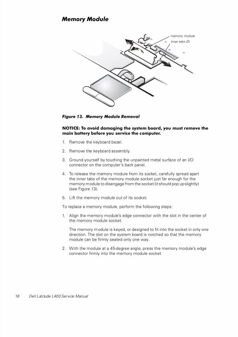
Figure 13. Memory Module Removal . . . . . . . . . . . . . . . . . . . . . . . . . . . . . .18Figure 14. Removing the Palmrest Assembly Bottom Screws. . . . . . . . . . . 19
Figure 15. Removing the Palmrest Assembly Top Screws. . . . . . . . . . . . . . 20
Figure 16. Touch Pad Removal . . . . . . . . . . . . . . . . . . . . . . . . . . . . . . . . . . .21
Figure 17. Bottom Assembly . . . . . . . . . . . . . . . . . . . . . . . . . . . . . . . . . . . 22
Figure 18. Reserve Battery Removal . . . . . . . . . . . . . . . . . . . . . . . . . . . . . .23
Figure 19. Modem Removal . . . . . . . . . . . . . . . . . . . . . . . . . . . . . . . . . . . . . 24
Figure 20. Fan Removal . . . . . . . . . . . . . . . . . . . . . . . . . . . . . . . . . . . . . . . . 25
Figure 21. Speaker Removal. . . . . . . . . . . . . . . . . . . . . . . . . . . . . . . . . . . . . 27
Figure 22. System Board Assembly Removal. . . . . . . . . . . . . . . . . . . . . . . .29
Figure 23. Hard-Disk Drive EMI Clip . . . . . . . . . . . . . . . . . . . . . . . . . . . . . . . 31Figure 24. Main Battery Release Latch Removal . . . . . . . . . . . . . . . . . . . . . 32
Tables Table 1. Screw Placement Mat With Component Screw Countsand Sizes . . . . . . . . . . . . . . . . . . . . . . . . . . . . . . . . . . . . . . . . . . . . 4

8/6/2019 Laptop Dell l 400
http://slidepdf.com/reader/full/laptop-dell-l-400 5/40
support.dell.com Dell Latitude L400 Service Manual 1
Dell™ Latitude™ L400 Service
Manual
This manual provides instructions for removing and replacing field-replaceable
components, assemblies, and subassemblies in your Dell Latitude computer.
Unless otherwise noted, each procedure in this manual assumes the following
conditions:
• The computer and any attached peripherals are turned off, and the
peripherals are disconnected from the I/O panel on the back and right side
of the computer.
• A part can be replaced by performing the removal procedure in reverse
order unless otherwise noted.
When the display assembly is open nearly 180 degrees, use a book or
something similar to support it. The angle of the display assembly with
respect to the bottom case should never exceed 180 degrees. Also, when
performing the procedures in this manual, the locations or directions relative
to the computer are as shown in Figure 1 unless otherwise specified.
Figure 1. Computer Orientation
right side left side
back of computer
front of computer
8/6/2019 Laptop Dell l 400
http://slidepdf.com/reader/full/laptop-dell-l-400 6/40
2 Dell Latitude L400 Service Manual
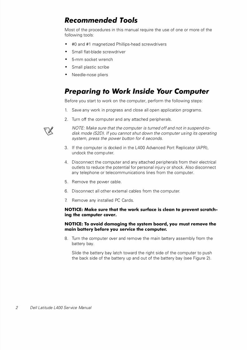
Recommended ToolsMost of the procedures in this manual require the use of one or more of the
following tools:
• #0 and #1 magnetized Phillips-head screwdrivers
• Small flat-blade screwdriver
• 5-mm socket wrench• Small plastic scribe
• Needle-nose pliers
Preparing to Work Inside Your Computer Before you start to work on the computer, perform the following steps:
1. Save any work in progress and close all open application programs.
2. Turn off the computer and any attached peripherals.
NOTE: Make sure that the computer is turned off and not in suspend-to-
disk mode (S2D). If you cannot shut down the computer using its operating
system, press the power button for 4 seconds.
3. If the computer is docked in the L400 Advanced Port Replicator (APR),
undock the computer.
4. Disconnect the computer and any attached peripherals from their electrical
outlets to reduce the potential for personal injury or shock. Also disconnect
any telephone or telecommunications lines from the computer.
5. Remove the power cable.
6. Disconnect all other external cables from the computer.
7. Remove any installed PC Cards.
NOTICE: Make sure that the work surface is clean to prevent scratch-ing the computer cover.
NOTICE: To avoid damaging the system board, you must remove themain battery before you service the computer.
8. Turn the computer over and remove the main battery assembly from the
battery bay.
Slide the battery bay latch toward the right side of the computer to push
the back side of the battery up and out of the battery bay (see Figure 2).

8/6/2019 Laptop Dell l 400
http://slidepdf.com/reader/full/laptop-dell-l-400 7/40
support.dell.com Dell Latitude L400 Service Manual 3
Figure 2. Main Battery Assembly Removal
9. Ground yourself by touching the unpainted metal surface of an I/O
connector on the back of the computer.
NOTICE: While you work, periodically touch the I/O panel todissipate any static electricity that might harm components.
Screw Identification and TighteningThe illustrations in the following removal procedures provide lengths of the
correct screws for each procedure. Figure 3 shows examples. Match the actual
screw to the illustration to check for correct length.
Figure 3. Screw Identification
NOTICE: When reinstalling a screw, you must use a screw of thecorrect length. Otherwise, you could damage the hardware. Makesure that the screw is properly aligned with its corresponding hole,
and avoid overtightening.
battery
battery latch
8/6/2019 Laptop Dell l 400
http://slidepdf.com/reader/full/laptop-dell-l-400 8/40
4 Dell Latitude L400 Service Manual
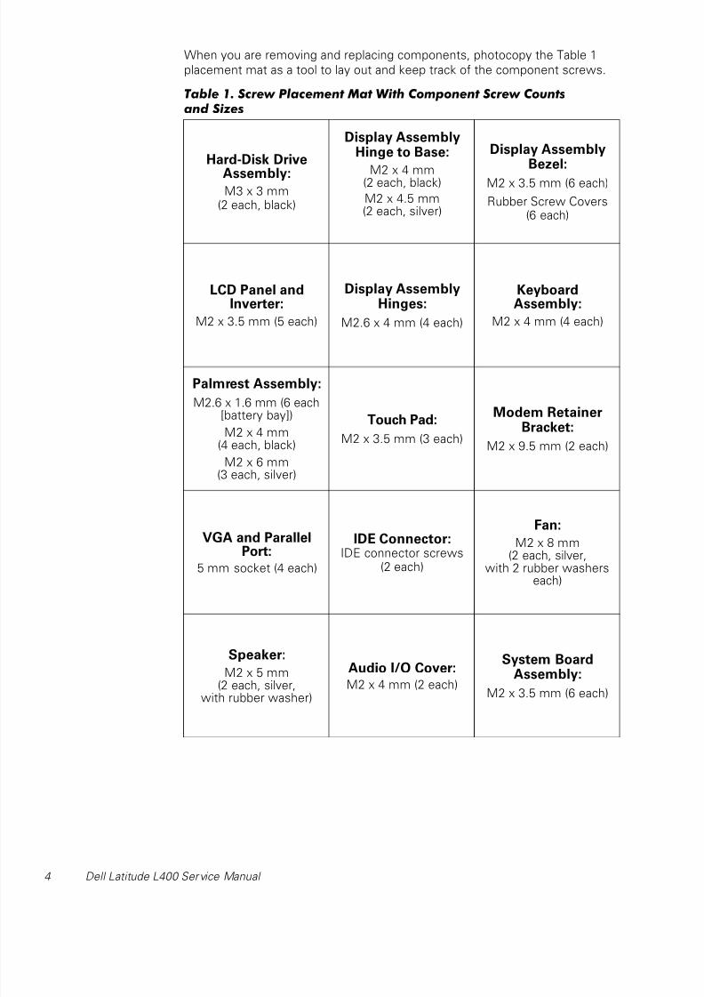
When you are removing and replacing components, photocopy the Table 1
placement mat as a tool to lay out and keep track of the component screws.
Table 1. Screw Placement Mat With Component Screw Countsand Sizes
Hard-Disk Drive
Assembly:M3 x 3 mm
(2 each, black)
Display AssemblyHinge to Base:
M2 x 4 mm(2 each, black)
M2 x 4.5 mm(2 each, silver)
Display AssemblyBezel:
M2 x 3.5 mm (6 each)
Rubber Screw Covers(6 each)
LCD Panel andInverter:
M2 x 3.5 mm (5 each)
Display AssemblyHinges:
M2.6 x 4 mm (4 each)
KeyboardAssembly:
M2 x 4 mm (4 each)
Palmrest Assembly:
M2.6 x 1.6 mm (6 each[battery bay])
M2 x 4 mm(4 each, black)
M2 x 6 mm(3 each, silver)
Touch Pad:
M2 x 3.5 mm (3 each)
Modem RetainerBracket:
M2 x 9.5 mm (2 each)
VGA and ParallelPort:
5 mm socket (4 each)
IDE Connector:IDE connector screws
(2 each)
Fan:M2 x 8 mm
(2 each, silver,with 2 rubber washers
each)
Speaker:
M2 x 5 mm(2 each, silver,
with rubber washer)
Audio I/O Cover:
M2 x 4 mm (2 each)
System BoardAssembly:
M2 x 3.5 mm (6 each)

8/6/2019 Laptop Dell l 400
http://slidepdf.com/reader/full/laptop-dell-l-400 9/40
support.dell.com Dell Latitude L400 Service Manual 5
ZIF ConnectorsSome of the computer’s interface connectors are zero insertion force (ZIF)
connectors. These connectors are not removable, but they must be released
to disconnect a cable from them (see Figure 4).
Figure 4. Disconnecting an Interface Cable
NOTICE: The ZIF connectors are fragile. To avoid damage, do notapply too much pressure to the movable part of the connector.
To disconnect an interface cable from a ZIF connector, perform the following
steps:
1. Insert a small flat-blade screwdriver under the movable part of the
connector.
2. Pull gently upward on the movable part of the connector until it releasesthe interface cable.
3. Grasp the interface cable and pull it out of the connector.
To reconnect an interface cable to a ZIF connector, perform the following
steps:
1. Use a small flat-blade screwdriver to open the movable part of the ZIF
connector.
2. Orient the end of the interface cable with the ZIF connector, and insert the
end of the cable into the connector.
3. While holding the cable in place, close the ZIF connector.
To ensure a firm connection, make sure the ZIF connector is completely
closed.
movable part of connector (do not remove)
8/6/2019 Laptop Dell l 400
http://slidepdf.com/reader/full/laptop-dell-l-400 10/40
6 Dell Latitude L400 Service Manual
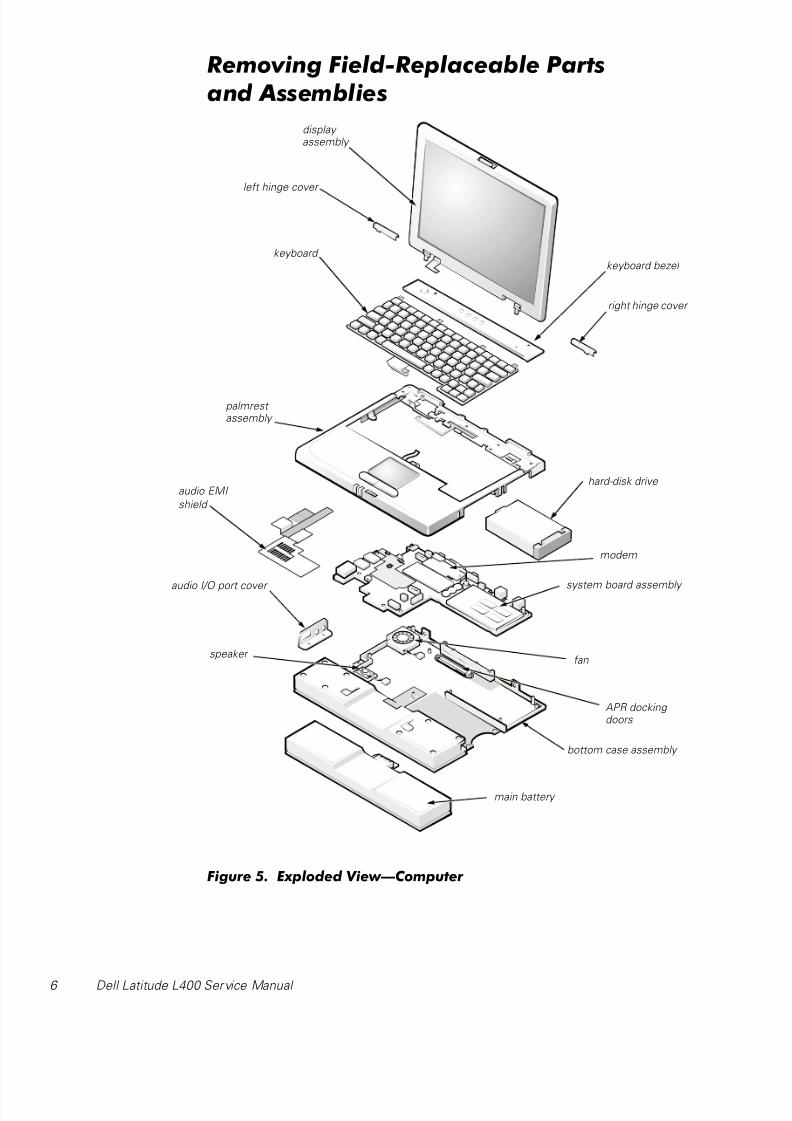
Removing Field-Replaceable Partsand Assemblies
Figure 5. Exploded View—Computer
display assembly
keyboard
palmrest assembly
system board assembly
hard-disk drive
main battery
bottom case assembly
right hinge cover
left hinge cover
audio EMI
shield
audio I/O port cover
keyboard bezel
speaker fan
APR docking doors
modem

8/6/2019 Laptop Dell l 400
http://slidepdf.com/reader/full/laptop-dell-l-400 11/40
support.dell.com Dell Latitude L400 Service Manual 7
The following subsections provide instructions for removing and replacing
field-replaceable parts and assemblies.
Hard-Disk Drive Assembly
Figure 6. Hard-Disk Drive Assembly Removal
NOTICE: To avoid damaging the system board, you must remove themain battery before you service the computer.
NOTICE: The hard-disk drive is very sensitive to shock. Handle theassembly by its edges (do not squeeze the top of the hard-disk drivecase), and avoid dropping it.
NOTICE: Make sure that the work surface is clean to preventscratching the computer cover.
1. Turn the computer over, and remove the two M3 x 3-mm screws from thebottom of the hard-disk drive door (see Figure 6).
The hard-disk drive is located on the right side of the computer.
2. Pull the drive out of the computer.
bottom of computer
hard-disk drive
M3 x 3-mm screws (2)

8/6/2019 Laptop Dell l 400
http://slidepdf.com/reader/full/laptop-dell-l-400 12/40
8 Dell Latitude L400 Service Manual
Keyboard Bezel
Figure 7. Keyboard Bezel Removal
NOTICE: To avoid damaging the system board, you must remove themain battery before you service the computer.
NOTICE: To avoid damaging the microphone, do not put any objectsinto the microphone hole (see Figure 7).
1. Place the point of a paper clip or a tool of similar size in the keyboard bezel
hole and carefully push down (see Figure 7).
2. While pushing down, slide the keyboard bezel to the left until it releases.
3. Lift the keyboard bezel.
keyboard bezel release hole
keyboard bezel
microphone hole
8/6/2019 Laptop Dell l 400
http://slidepdf.com/reader/full/laptop-dell-l-400 13/40
support.dell.com Dell Latitude L400 Service Manual 9
Display Assembly
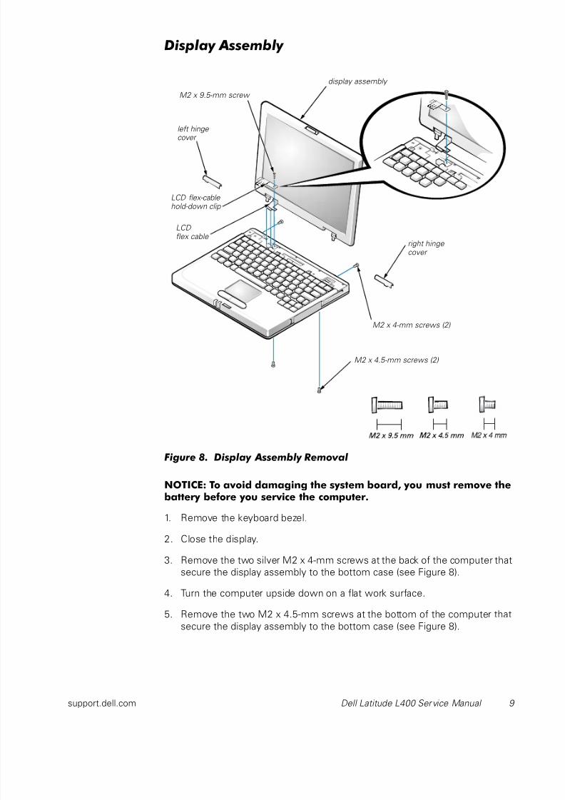
Figure 8. Display Assembly Removal
NOTICE: To avoid damaging the system board, you must remove thebattery before you service the computer.
1. Remove the keyboard bezel.
2. Close the display.
3. Remove the two silver M2 x 4-mm screws at the back of the computer thatsecure the display assembly to the bottom case (see Figure 8).
4. Turn the computer upside down on a flat work surface.
5. Remove the two M2 x 4.5-mm screws at the bottom of the computer that
secure the display assembly to the bottom case (see Figure 8).
LCD flex-cable hold-down clip
M2 x 9.5-mm screw
right hinge cover
LCD flex cable
M2 x 4-mm screws (2)
display assembly
left hinge
cover
M2 x 4.5-mm screws (2)
8/6/2019 Laptop Dell l 400
http://slidepdf.com/reader/full/laptop-dell-l-400 14/40
10 Dell Latitude L400 Service Manual
6. Turn the computer right-side up.
7. Open the display.
8. Remove the left and right hinge covers.
NOTE: When replacing the display assembly, the left hinge cover must go
over the left hinge and the right hinge cover must go over the right hinge.
They are not interchangeable. An L is stamped on the bottom of the left
hinge cover and an R is stamped on the bottom of the right hinge cover.
9. Remove the M2 x 9.5-mm screw that secures the LCD flex-cable
hold-down clip and the LCD flex-cable connector to the system board
assembly (see Figure 8).
The M2 x 9.5-mm screw also secures the left side of the modem retainer
bracket to the system board assembly.
10. Carefully disconnect the LCD flex-cable connector from the system board.
11. Lift the display assembly from the bottom assembly.
To replace the display assembly, perform the following steps:
1. Place the display assembly on the bottom assembly.
Insert the left and right hinge posts into the holes at the top of the
palmrest.
2. Carefully connect the LCD flex cable to the connector on the system
board.
3. Place the LCD flex-cable hold-down clip over the LCD flex-cable connector
(see Figure 8).
The tab at the left of the clip should go under the palm rest, and the screw
hole on the right side of the clip should line up with the holes in the
connector ground strip and the threaded hole in the system board.
4. Reinstall the M2 x 9.5-mm screw that secures the LCD flex-cable
hold-down clip to the system board.
5. Close the display.
You may have to press down on the back end of the display (above the
hinges) while closing the display to get the display to close completely.
6. Reinstall the two M2 x 4.5-mm screws that secure the display assembly tothe bottom case.
You may have to squeeze the display assembly and the bottom assembly
together, so the screw holes align in the base assembly and the hinge
posts.
Do not completely tighten the screws.
8/6/2019 Laptop Dell l 400
http://slidepdf.com/reader/full/laptop-dell-l-400 15/40
support.dell.com Dell Latitude L400 Service Manual 11
7. Reinstall the two M2 x 4-mm screws in the back of the computer that
secure the display assembly to the back of the bottom case.
8. Tighten the two screws that you installed in step 6.
9. Open the display and reinstall the left and right hinge covers.
An L is stamped on the bottom of the left hinge cover and an R is stamped
on the bottom of the right hinge cover.
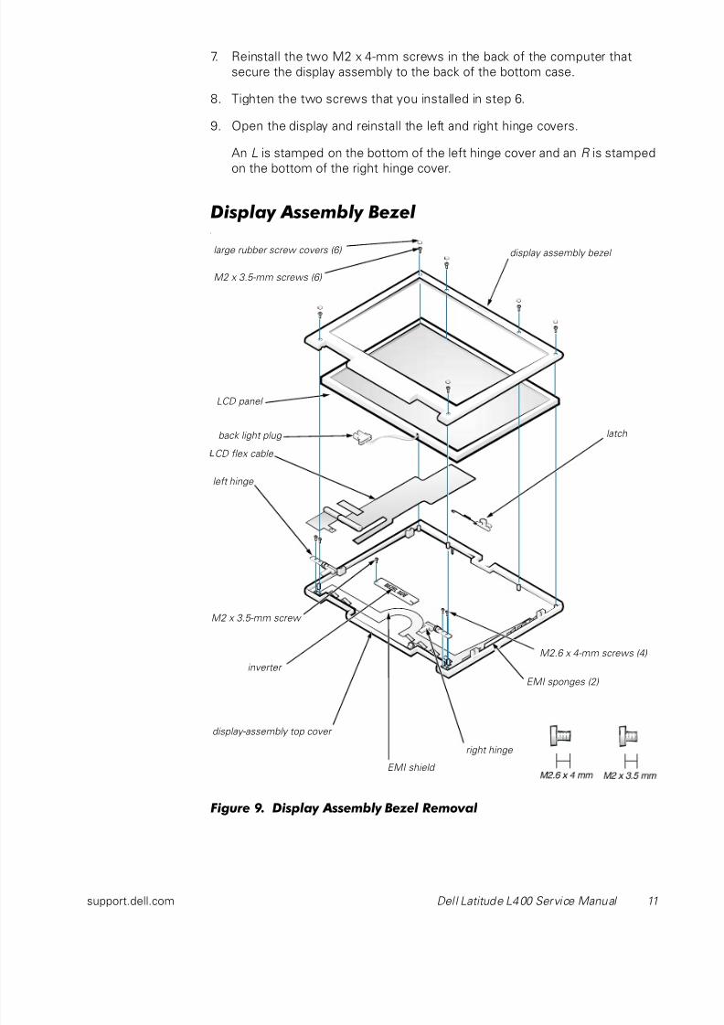
Display Assembly Bezell
Figure 9. Display Assembly Bezel Removal
LCD panel
display-assembly top cover
inverter
display assembly bezel large rubber screw covers (6)
M2 x 3.5-mm screws (6)
latch
left hinge
right hinge
M2.6 x 4-mm screws (4)
M2 x 3.5-mm screw
back light plug
EMI sponges (2)
CD flex cable
EMI shield
8/6/2019 Laptop Dell l 400
http://slidepdf.com/reader/full/laptop-dell-l-400 16/40
12 Dell Latitude L400 Service Manual
NOTICE: To avoid damaging the system board, you must remove themain battery before you service the computer.
1. Use a scribe to carefully pry the six rubber screw covers out of the six
screw holes located along the top and bottom of the bezel on the front of
the display assembly (see Figure 9).
2. Remove the six M2 x 3.5-mm screws located at the top and bottom of the
bezel on the front of the display assembly (see Figure 9).
3. Separate the bezel from the display-assembly top cover.
The bezel is secured by slot openings that snap into the display-assembly
top cover. Carefully lift the inside edge of the bezel, working your way
around the inside perimeter, to unsnap and remove the bezel from the
display assembly.
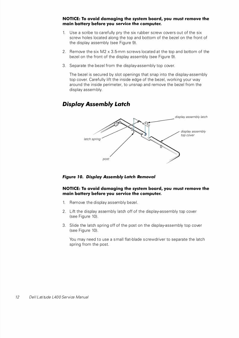
Display Assembly Latch
Figure 10. Display Assembly Latch Removal
NOTICE: To avoid damaging the system board, you must remove themain battery before you service the computer.
1. Remove the display assembly bezel.
2. Lift the display assembly latch off of the display-assembly top cover
(see Figure 10).
3. Slide the latch spring off of the post on the display-assembly top cover
(see Figure 10).
You may need to use a small flat-blade screwdriver to separate the latch
spring from the post.
display assembly latch
latch spring
post
display assembly top cover

8/6/2019 Laptop Dell l 400
http://slidepdf.com/reader/full/laptop-dell-l-400 17/40
support.dell.com Dell Latitude L400 Service Manual 13
To replace the display-assembly latch, perform the following steps:
1. Carefully place the latch spring over the post on the display-assembly top
cover.
You may need to use a small flat-blade screwdriver to place the spring over
the post. Hold the spring on the post with the screwdriver while
performing the next step.
2. Holding the latch, stretch the spring slightly and set the display-assemblylatch in place in the display assembly top cover.
3. Reinstall the bezel.
LCD Panel
Figure 11. LCD Panel Removal
NOTICE: To avoid damaging the system board, you must remove themain battery before you service the computer.
1. Ground yourself by touching the unpainted metal surface of the I/O panel
on the back of the computer.
LCD panel
wide flex cable
LCD flex cable
back light plug
M2 x 3.5-mm screws (4)
back light plug
inverter
inverter
narrow flex cable
ZIF connector
M2 x 3.5-mmscrew
EMI sponges (2)
narrow flex cable
EMI shield

8/6/2019 Laptop Dell l 400
http://slidepdf.com/reader/full/laptop-dell-l-400 18/40
14 Dell Latitude L400 Service Manual
2. Remove the keyboard bezel.
3. Remove the display assembly.
4. Remove the display assembly bezel.
5. Remove the four M2 x 3.5-mm screws on the left and right sides of
the display assembly that secure the LCD panel to the top cover
(see Figure 11).
6. Remove the M2 x 3.5-mm screw that secures the inverter to the top cover.
7. Lift and roll the inverter over (toward you), so the bezel side is down and
the connector side is up (see Figure 11).
8. Disconnect the narrow flex cable from the ZIF connector on the left side of
the inverter.
9. Disconnect the two-wire back-light plug from the connector on the right
side of the inverter (see Figure 11).
10. Remove the inverter.
11. Lift the LCD panel from the bottom edge, giving enough room to fit your
hand between the LCD panel and the top cover.
12. Carefully peel the LCD flex cable away from the top cover.
13. Lift the LCD panel out of the top cover.
14. Lift up on the tape that is covering the wide flex-cable connector on the
back of the LCD panel.
NOTE: Keep the tape for when you replace the LCD panel.
15. Disconnect the wide flex cable from the connector on the back of the LCDpanel.
To replace the LCD panel, perform the following steps:
1. Connect the LCD flex cable to the connector on the back of the LCD panel.
2. Reinstall the tape that covers the LCD flex-cable connector on the back of
the LCD panel.
3. If you are installing a new LCD flex cable, peel off the backing tapes that
are on the LCD flex-cable EMI sponges.
4. Reinstall the LCD panel in the top cover.
a. Holding the LCD flex cable against the back of the LCD panel, insert
the right edge of the LCD panel into the right end of the top cover.
The right edge of the LCD panel should press against the EMI sponge
on the right side of the top cover. The LCD panel should not rest on top
of the EMI sponge.
8/6/2019 Laptop Dell l 400
http://slidepdf.com/reader/full/laptop-dell-l-400 19/40
support.dell.com Dell Latitude L400 Service Manual 15
b. Lower the bottom end of the LCD panel into the top cover, making sure
the LCD flex cable lines up with the opening that is to the right of the
left hinge.
c. Make sure the narrow part of the flex cable that goes to the inverter is
visible at the bottom edge of the LCD panel.
d. Press the LCD panel into the top cover.
5. Connect the narrow flex cable to the ZIF connector on the left side of theinverter.
6. With the connector side of the inverter facing up, connect the two-wire
back-light plug to the connector on the right end of the inverter.
When the plug is all the way in the connector, the key slot in the center of
the plug should not be visible. If you can see the key slot, the plug is not in
the connector correctly. Pull the plug out, turn the plug over, and reinsert it
into the connector.
7. Roll the inverter over (away from you), so the connector side of the inverter
is up.
8. Place the inverter into the top cover, aligning the posts in the top cover
with the alignment holes in the inverter.
9. Holding the inverter in place, reinstall the M2 x 3.5-mm screw that secures
the inverter to the top cover.
10. Reinstall the four M2 x 3.5-mm screws, in the left and right ends of the top
cover, that secure the LCD panel to the top cover.
11. Reinstall the display assembly latch.
12. Reinstall the display assembly bezel.
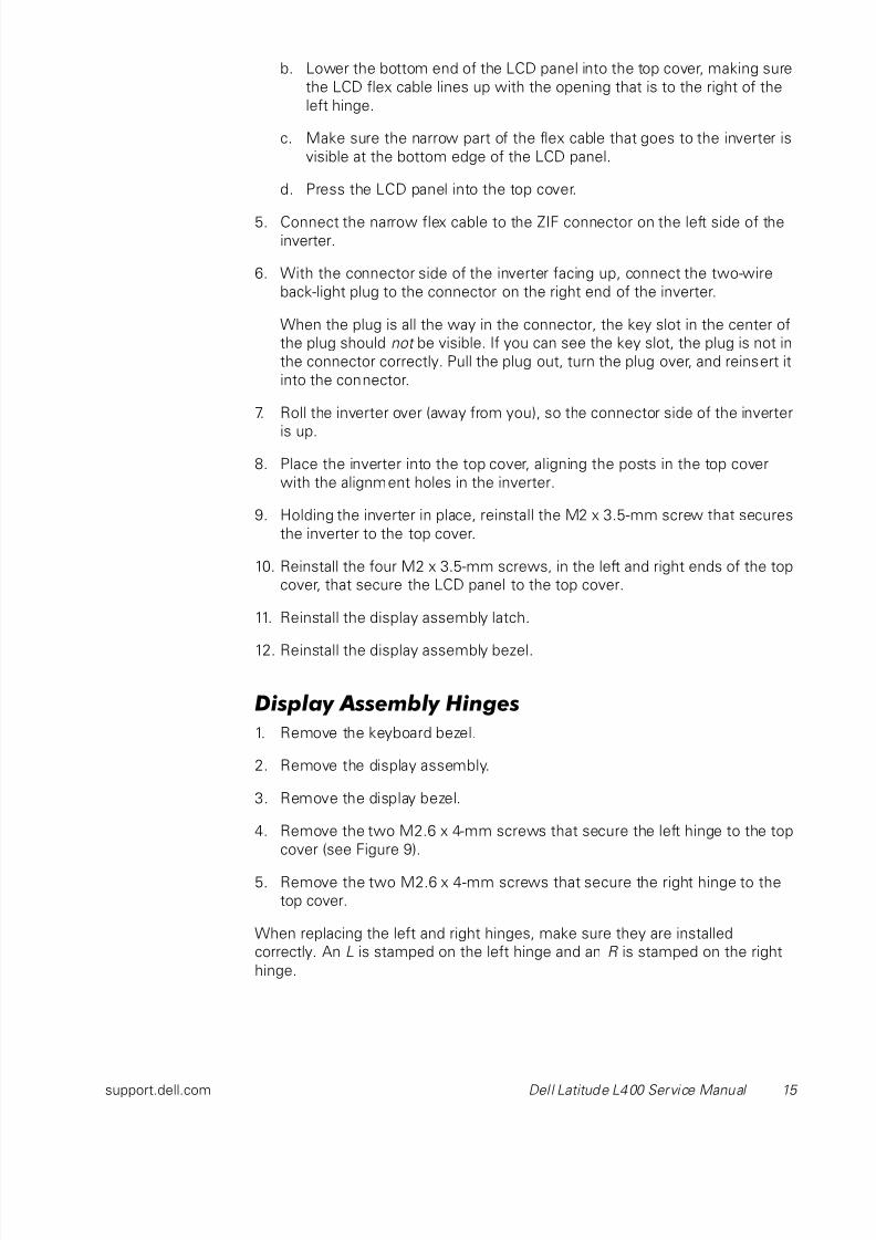
Display Assembly Hinges
1. Remove the keyboard bezel.
2. Remove the display assembly.
3. Remove the display bezel.
4. Remove the two M2.6 x 4-mm screws that secure the left hinge to the top
cover (see Figure 9).
5. Remove the two M2.6 x 4-mm screws that secure the right hinge to the
top cover.
When replacing the left and right hinges, make sure they are installed
correctly. An L is stamped on the left hinge and an R is stamped on the right
hinge.
8/6/2019 Laptop Dell l 400
http://slidepdf.com/reader/full/laptop-dell-l-400 20/40
16 Dell Latitude L400 Service Manual
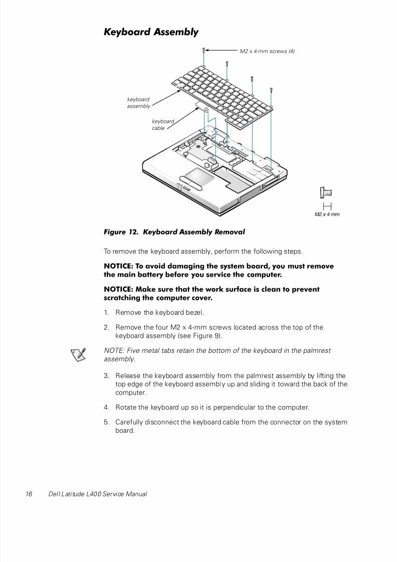
Keyboard Assembly
Figure 12. Keyboard Assembly Removal
To remove the keyboard assembly, perform the following steps.
NOTICE: To avoid damaging the system board, you must removethe main battery before you service the computer.
NOTICE: Make sure that the work surface is clean to prevent
scratching the computer cover.
1. Remove the keyboard bezel.
2. Remove the four M2 x 4-mm screws located across the top of the
keyboard assembly (see Figure 9).
NOTE: Five metal tabs retain the bottom of the keyboard in the palmrest
assembly.
3. Release the keyboard assembly from the palmrest assembly by lifting the
top edge of the keyboard assembly up and sliding it toward the back of the
computer.
4. Rotate the keyboard up so it is perpendicular to the computer.
5. Carefully disconnect the keyboard cable from the connector on the system
board.
M2 x 4-mm screws (4)
keyboard assembly
keyboard
cable
8/6/2019 Laptop Dell l 400
http://slidepdf.com/reader/full/laptop-dell-l-400 21/40
support.dell.com Dell Latitude L400 Service Manual 17
NOTICE: The keycaps on the keyboard are fragile, easily dislodged,and time-consuming to replace. Be careful when removing andhandling the keyboard.
6. Remove the keyboard assembly.
To replace the keyboard assembly, perform the following steps.
NOTICE: Position the keyboard cable so it is not twisted when it is
connected to the system board.
1. Connect the keyboard cable to the connector on the system board.
NOTE: Five metal tabs retain the bottom of the keyboard in the palmrest
assembly.
2. Fit the keyboard into place by sliding the five tabs on the bottom of the
keyboard into the palmrest assembly.
It is important that the two tabs on the bottom right edge of the keyboard
assembly fit correctly into the slotted holes in the palmrest assembly. To
help align the tabs with the slotted holes, you can temporarily insert thehard-disk drive into the hard-disk drive bay before you place the keyboard
assembly in the palmrest assembly. By resting the keyboard assembly on
the hard-disk drive, the tabs will be at the correct height to enter the
slotted holes. When the keyboard assembly is seated in the palmrest
assembly, remove the hard-disk drive and look through the hard-disk drive
bay to make sure the tabs are seated in the slot holes.
3. Ensure that the top screw-hole tabs rest correctly in the screw slots on the
palmrest assembly.
4. Verify that the keyboard is correctly installed.
The keys should be flush with the left and right surfaces of the palmrest.
5. Reinstall the four M2 x 4-mm screws that secure the top of the keyboard
assembly to the bottom assembly.
6. Reinstall the keyboard bezel.
8/6/2019 Laptop Dell l 400
http://slidepdf.com/reader/full/laptop-dell-l-400 22/40
8/6/2019 Laptop Dell l 400
http://slidepdf.com/reader/full/laptop-dell-l-400 23/40
support.dell.com Dell Latitude L400 Service Manual 19
3. Pivot the memory module down until it clicks into place.
If you do not hear a click as each end of the memory module snaps into the
tabs, remove the memory module and reinstall it (see Figure 13).
Palmrest Assembly
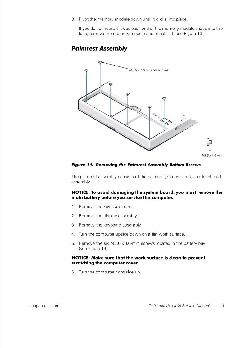
Figure 14. Removing the Palmrest Assembly Bottom Screws
The palmrest assembly consists of the palmrest, status lights, and touch pad
assembly.
NOTICE: To avoid damaging the system board, you must remove themain battery before you service the computer.
1. Remove the keyboard bezel.
2. Remove the display assembly.
3. Remove the keyboard assembly.
4. Turn the computer upside down on a flat work surface.
5. Remove the six M2.6 x 1.6-mm screws located in the battery bay(see Figure 14).
NOTICE: Make sure that the work surface is clean to preventscratching the computer cover.
6. Turn the computer right-side up.
M2.6 x 1.6-mm screws (6)

8/6/2019 Laptop Dell l 400
http://slidepdf.com/reader/full/laptop-dell-l-400 24/40
20 Dell Latitude L400 Service Manual
7. Remove the four black M2 x 4-mm screws across the top of the computer
(see Figure 15).
Figure 15. Removing the Palmrest Assembly Top Screws
8. Remove the three silver M2 x 6-mm screws in the keyboard-assembly
area that secure the middle of the palmrest assembly to the bottom case
(see Figure 15).
9. Disconnect the status lights flex cable from the ZIF connector on the
system board.
10. Disconnect the touch pad flex cable from the ZIF connector on the system
board.
11. Carefully remove the palmrest assembly from the bottom assembly.
M2 x 4-mm screws (4 black)
palmrest assembly
M2 x 6-mm screws (3 silver)
status lights flex cable
touch pad flex cable
8/6/2019 Laptop Dell l 400
http://slidepdf.com/reader/full/laptop-dell-l-400 25/40
support.dell.com Dell Latitude L400 Service Manual 21
To replace the palmrest assembly, perform the following steps:
1. Place the palmrest assembly on the bottom assembly.
2. Reinstall the three silver M2 x 6-mm screws in the keyboard-assembly area
that secure the middle of the palmrest assembly to the bottom-case
assembly (see Figure 15).
3. Reinstall the four black M2 x 4-mm screws that secure the top of the
palmrest assembly to the bottom-case assembly (see Figure 15).
4. Connect the touch pad flex cable to the ZIF connector on the system
board.
5. Connect the status lights flex cable to the ZIF connector on the system
board.
6. Turn the computer upside down.
7. Reinstall the six M2.6 x 1.6-mm screws in the battery bay that secure
the bottom of the palmrest assembly to the bottom-case assembly
(see Figure 14).
8. Turn the computer right-side up.
9. Reinstall the keyboard assembly.
10. Reinstall the display assembly.
11. Reinstall the keyboard bezel.
Touch Pad Assembly
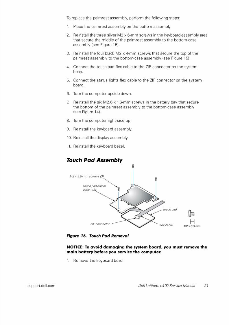
Figure 16. Touch Pad Removal
NOTICE: To avoid damaging the system board, you must remove themain battery before you service the computer.
1. Remove the keyboard bezel.
M2 x 3.5-mm screws (3)
flex cable ZIF connector
touch pad
touch pad holder assembly
8/6/2019 Laptop Dell l 400
http://slidepdf.com/reader/full/laptop-dell-l-400 26/40
22 Dell Latitude L400 Service Manual
2. Remove the display assembly.
3. Remove the keyboard assembly.
4. Remove the palmrest assembly.
5. Remove the three M2 x 3.5-mm screws that secure the touch pad
assembly to the palmrest assembly (see Figure 16).
6. Slide the touch pad assembly out from under the two hold-down tabs.
7. Remove the touch pad assembly from the palmrest assembly.
8. Disconnect the flex cable from the ZIF connector on the back of the touch
pad (see Figure 16).
The flex cable remains attached to the touch pad holder assembly.
Bottom Assembly
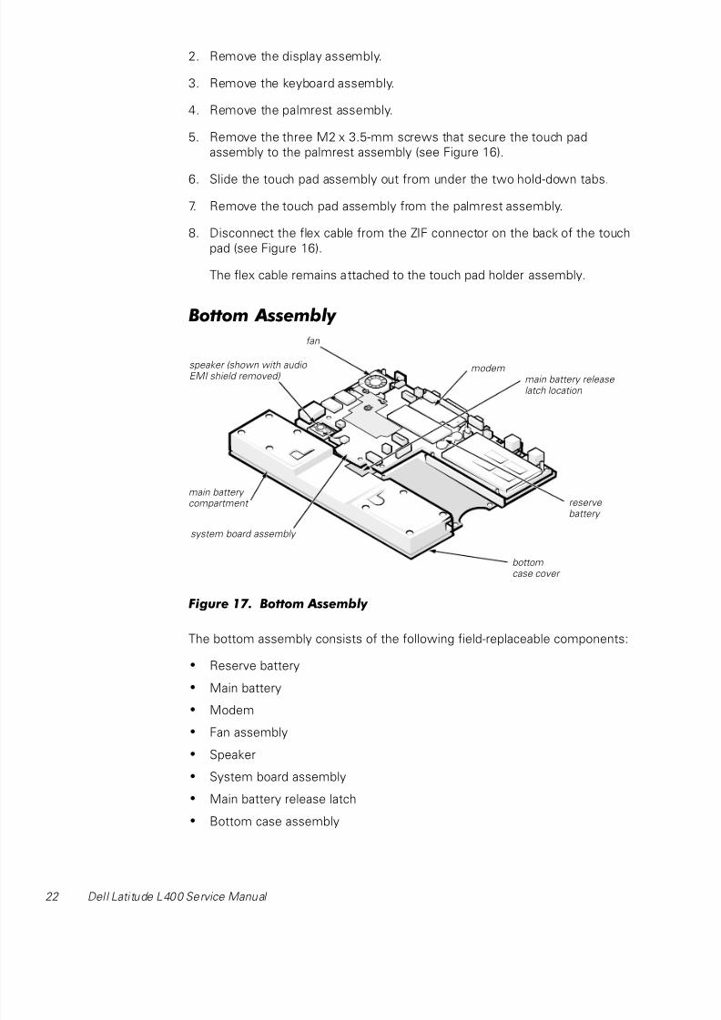
Figure 17. Bottom Assembly
The bottom assembly consists of the following field-replaceable components:
• Reserve battery
• Main battery
• Modem• Fan assembly
• Speaker
• System board assembly
• Main battery release latch
• Bottom case assembly
reserve battery
fan
main battery compartment
system board assembly
bottomcase cover
main battery release latch location
modemspeaker (shown with audio EMI shield removed)
8/6/2019 Laptop Dell l 400
http://slidepdf.com/reader/full/laptop-dell-l-400 27/40
support.dell.com Dell Latitude L400 Service Manual 23
Reserve Battery
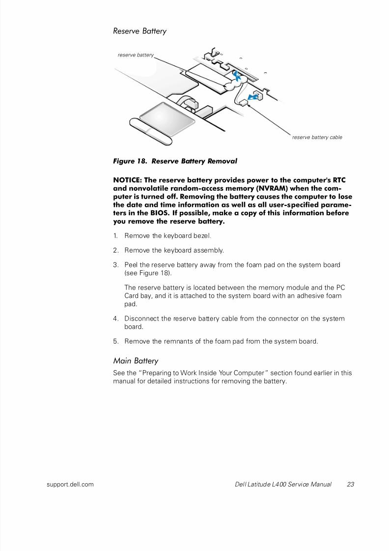
Figure 18. Reserve Battery Removal
NOTICE: The reserve battery provides power to the computer's RTCand nonvolatile random-access memory (NVRAM) when the com-puter is turned off. Removing the battery causes the computer to losethe date and time information as well as all user-specified parame-ters in the BIOS. If possible, make a copy of this information before you remove the reserve battery.
1. Remove the keyboard bezel.
2. Remove the keyboard assembly.
3. Peel the reserve battery away from the foam pad on the system board
(see Figure 18).
The reserve battery is located between the memory module and the PCCard bay, and it is attached to the system board with an adhesive foam
pad.
4. Disconnect the reserve battery cable from the connector on the system
board.
5. Remove the remnants of the foam pad from the system board.
Main Battery
See the “Preparing to Work Inside Your Computer” section found earlier in this
manual for detailed instructions for removing the battery.
reserve battery cable
reserve battery
8/6/2019 Laptop Dell l 400
http://slidepdf.com/reader/full/laptop-dell-l-400 28/40
24 Dell Latitude L400 Service Manual
Modem
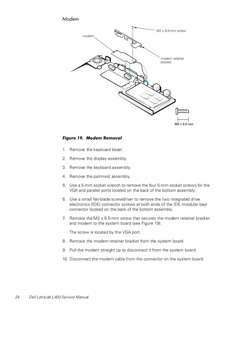
Figure 19. Modem Removal
1. Remove the keyboard bezel.
2. Remove the display assembly.
3. Remove the keyboard assembly.
4. Remove the palmrest assembly.
5. Use a 5-mm socket wrench to remove the four 5-mm socket screws for the
VGA and parallel ports located on the back of the bottom assembly.
6. Use a small flat-blade screwdriver to remove the two integrated drive
electronics (IDE) connector screws at both ends of the IDE (modular bay)
connector located on the back of the bottom assembly.
7. Remove the M2 x 9.5-mm screw that secures the modem retainer bracket
and modem to the system board (see Figure 19).
The screw is located by the VGA port.
8. Remove the modem retainer bracket from the system board.
9. Pull the modem straight up to disconnect it from the system board.
10. Disconnect the modem cable from the connector on the system board.
M2 x 9.5-mm screw
modem retainer bracket
modem
8/6/2019 Laptop Dell l 400
http://slidepdf.com/reader/full/laptop-dell-l-400 29/40
support.dell.com Dell Latitude L400 Service Manual 25
To replace the modem, perform the following steps:
1. Connect the modem cable to the connector on the system board.
2. Align the connector on the bottom of the modem with the connector on
the system board, and carefully press the modem onto the system board.
3. Put the modem retainer bracket in place.
4. Reinstall the M2 x 9.5-mm screw to secure the modem retainer bracketand modem to the system board.
5. Reinstall the two IDE connector screws at both ends of the IDE (modular
bay) connector located on the back of the bottom assembly.
6. Reinstall the four 5-mm socket screws for the VGA and parallel ports
located on the back of the bottom assembly.
7. Reinstall the palmrest assembly.
8. Reinstall the keyboard assembly.
9. Reinstall the display assembly.
10. Reinstall the keyboard bezel.
Fan
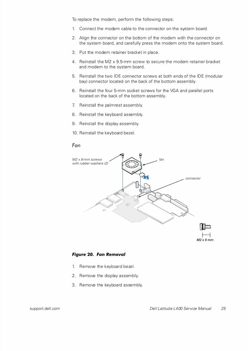
Figure 20. Fan Removal
1. Remove the keyboard bezel.
2. Remove the display assembly.
3. Remove the keyboard assembly.
connector
fanM2 x 8-mm screws with rubber washers (2)
8/6/2019 Laptop Dell l 400
http://slidepdf.com/reader/full/laptop-dell-l-400 30/40
26 Dell Latitude L400 Service Manual
4. Remove the palmrest assembly.
5. Carefully disconnect the fan wire connector from the system board
(see Figure 20).
The male connector on the fan wire is keyed to fit into the female
connector one way only.
6. Remove the two M2 x 8-mm screws with double rubber washers that
secure the fan to the bottom assembly (see Figure 20).
7. Remove the fan from the bottom assembly.
To replace the fan, perform the following steps:
1. Place the fan in the bottom assembly.
NOTE: Make sure that the fan wire is pointing toward the connector on the
system board assembly.
2. Reinstall the M2 x 8-mm screws with double rubber washers to secure the
fan to the bottom assembly.
NOTE: Make sure that the two M2 x 8-mm screws are installed with two rub-
ber washers apiece.
3. Reconnect the fan wire to the connector on the system board assembly.
4. Replace the palmrest assembly.
5. Replace the keyboard assembly.
6. Replace the display assembly.
7. Replace the keyboard bezel.

8/6/2019 Laptop Dell l 400
http://slidepdf.com/reader/full/laptop-dell-l-400 31/40
support.dell.com Dell Latitude L400 Service Manual 27
Speaker
Figure 21. Speaker Removal
1. Remove the keyboard bezel.
2. Remove the display assembly.
3. Remove the keyboard assembly.
4. Remove the palmrest assembly.
NOTICE: To ensure maximum cooling for the microprocessor, do nottouch the glue side of the thermal conductive tape. The oils in yourskin reduce the heat transfer capability on the glue side of the tape.
5. Peel up the EMI adhesive sponge that connects the audio EMI shield to
the thermal cooling solution (see Figure 21).
You only need to peel up the part of the sponge that lies on the thermal
cooling solution. The end of the sponge that lies on the audio EMI shield
can remain.
audio EMI shield
EMI adhesive sponge
speaker withrubber gasket
speaker wire
connector
M2 x 5-mm screws (2) with rubber washers
8/6/2019 Laptop Dell l 400
http://slidepdf.com/reader/full/laptop-dell-l-400 32/40
28 Dell Latitude L400 Service Manual
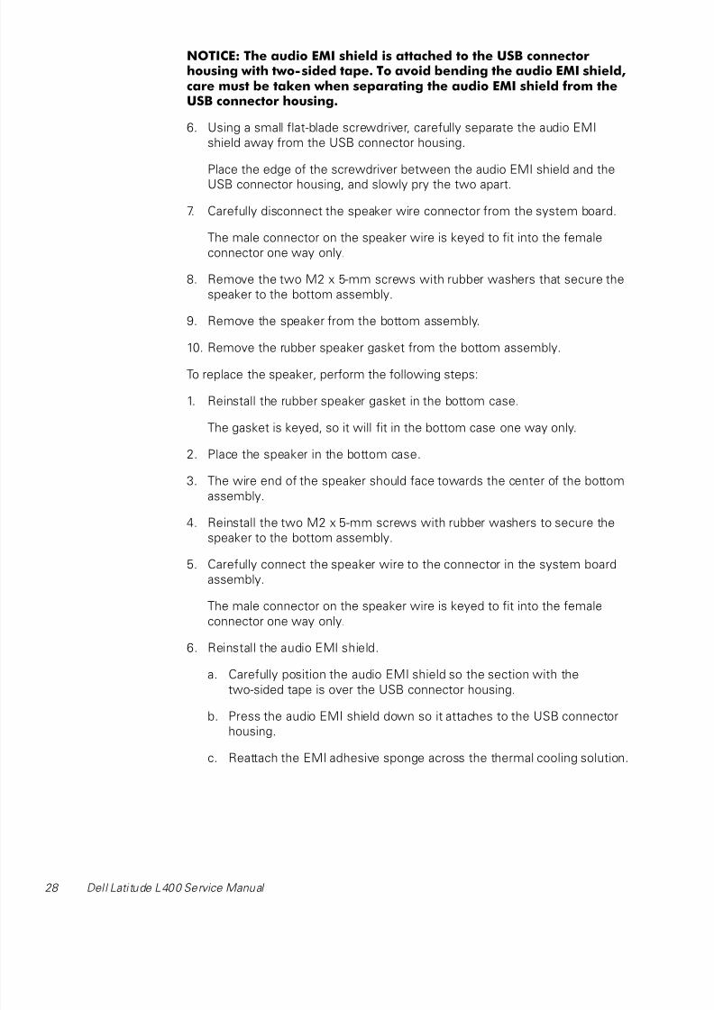
NOTICE: The audio EMI shield is attached to the USB connectorhousing with two-sided tape. To avoid bending the audio EMI shield,care must be taken when separating the audio EMI shield from theUSB connector housing.
6. Using a small flat-blade screwdriver, carefully separate the audio EMI
shield away from the USB connector housing.
Place the edge of the screwdriver between the audio EMI shield and the
USB connector housing, and slowly pry the two apart.
7. Carefully disconnect the speaker wire connector from the system board.
The male connector on the speaker wire is keyed to fit into the female
connector one way only.
8. Remove the two M2 x 5-mm screws with rubber washers that secure the
speaker to the bottom assembly.
9. Remove the speaker from the bottom assembly.
10. Remove the rubber speaker gasket from the bottom assembly.
To replace the speaker, perform the following steps:
1. Reinstall the rubber speaker gasket in the bottom case.
The gasket is keyed, so it will fit in the bottom case one way only.
2. Place the speaker in the bottom case.
3. The wire end of the speaker should face towards the center of the bottom
assembly.
4. Reinstall the two M2 x 5-mm screws with rubber washers to secure the
speaker to the bottom assembly.
5. Carefully connect the speaker wire to the connector in the system board
assembly.
The male connector on the speaker wire is keyed to fit into the female
connector one way only.
6. Reinstall the audio EMI shield.
a. Carefully position the audio EMI shield so the section with the
two-sided tape is over the USB connector housing.
b. Press the audio EMI shield down so it attaches to the USB connector
housing.
c. Reattach the EMI adhesive sponge across the thermal cooling solution.
8/6/2019 Laptop Dell l 400
http://slidepdf.com/reader/full/laptop-dell-l-400 33/40
support.dell.com Dell Latitude L400 Service Manual 29
7. Reinstall the palmrest assembly.
8. Reinstall the keyboard assembly.
9. Reinstall the display assembly.
10. Reinstall the keyboard bezel.
System Board Assembly6
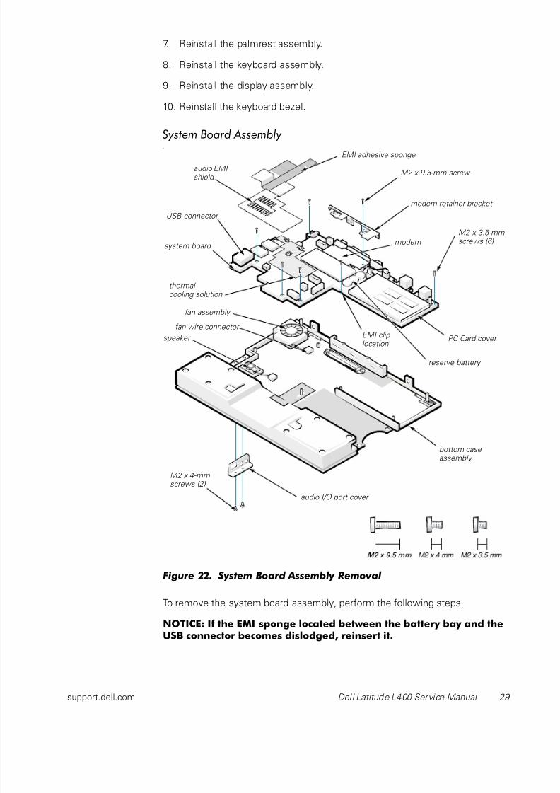
Figure 22. System Board Assembly Removal
To remove the system board assembly, perform the following steps.
NOTICE: If the EMI sponge located between the battery bay and theUSB connector becomes dislodged, reinsert it.
PC Card cover
system board
fan assembly
M2 x 9.5-mm screw
audio I/O port cover
audio EMI shield
fan wire connector
M2 x 4-mmscrews (2)
thermal cooling solution
M2 x 3.5-mmscrews (6)
modem retainer bracket
modem
reserve battery
bottom case assembly
EMI clip location
EMI adhesive sponge
speaker
USB connector
8/6/2019 Laptop Dell l 400
http://slidepdf.com/reader/full/laptop-dell-l-400 34/40
30 Dell Latitude L400 Service Manual
NOTICE: To avoid damaging the system board, you must remove themain battery before you service the computer.
NOTICE: The processor is not replaceable. Do not attempt to removethe thermal cooling solution.
1. Remove the keyboard bezel.
2. Remove the display assembly.
3. Remove the keyboard.
4. Remove the palmrest assembly.
5. Use a 5-mm socket wrench to remove the four 5-mm socket screws for the
VGA and parallel ports located on the back of the bottom case assembly.
6. Use a small flat-blade screwdriver to remove the two IDE connector
screws at both ends of the IDE (modular bay) connector located on the
back of the bottom case assembly.
NOTICE: To ensure maximum cooling for the microprocessor, do nottouch the glue side of the thermal conductive tape. The oils in yourskin reduce the heat transfer capability on the glue side of the tape.
7. Peel up the EMI adhesive sponge that connects the audio EMI shield to
the thermal cooling solution (see Figure 22).
You only need to peel up the part of the sponge that lays on the thermal
cooling solution. The end of the sponge that lays on the audio EMI shield
can remain.
NOTICE: The audio EMI shield is attached to the USB connectorhousing with two-sided tape. To avoid bending the audio EMI shield,
care must be taken when separating the audio EMI shield from theUSB connector housing.
8. Using a small flat-blade screwdriver, carefully separate the audio EMI
shield away from the USB connector housing.
Place the edge of the screwdriver between the audio EMI shield and the
USB connector housing, and slowly pry the two apart.
9. Remove the two M2 x 4-mm screws that secure the audio I/O cover to the
bottom case assembly.
10. Remove the audio I/O cover.
11. Remove the six M2 x 3.5-mm screws that secure the system board to the
bottom case assembly.
White arrows on the system board assembly point to the
M2 x 3.5-mm screws.
12. Remove the M2 x 9.5-mm screw that secures the modem retainer bracket.
8/6/2019 Laptop Dell l 400
http://slidepdf.com/reader/full/laptop-dell-l-400 35/40
support.dell.com Dell Latitude L400 Service Manual 31
13. Remove the modem retainer bracket from the bottom case assembly.
14. Disconnect the speaker wire from the connector on the system board
assembly.
15. Disconnect the fan wire from the connector on the system board
assembly.
16. Lift the system board assembly out of the bottom case assembly.
To replace the system board assembly, perform the following steps:
1. Transfer the memory module(s) to the replacement system board
assembly.
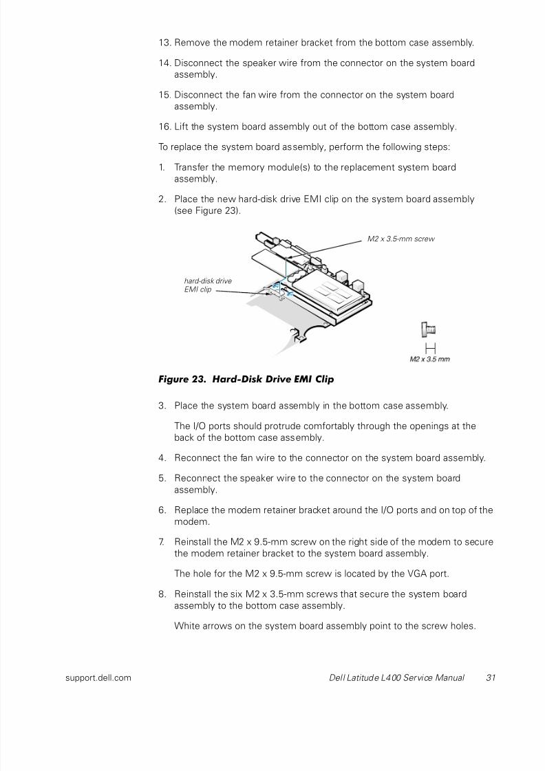
2. Place the new hard-disk drive EMI clip on the system board assembly
(see Figure 23).
Figure 23. Hard-Disk Drive EMI Clip
3. Place the system board assembly in the bottom case assembly.
The I/O ports should protrude comfortably through the openings at the
back of the bottom case assembly.
4. Reconnect the fan wire to the connector on the system board assembly.
5. Reconnect the speaker wire to the connector on the system board
assembly.
6. Replace the modem retainer bracket around the I/O ports and on top of the
modem.
7. Reinstall the M2 x 9.5-mm screw on the right side of the modem to securethe modem retainer bracket to the system board assembly.
The hole for the M2 x 9.5-mm screw is located by the VGA port.
8. Reinstall the six M2 x 3.5-mm screws that secure the system board
assembly to the bottom case assembly.
White arrows on the system board assembly point to the screw holes.
hard-disk drive EMI clip
M2 x 3.5-mm screw
8/6/2019 Laptop Dell l 400
http://slidepdf.com/reader/full/laptop-dell-l-400 36/40
32 Dell Latitude L400 Service Manual
One of the M2 x 3.5-mm screws passes through the hard-disk drive EMI
clip (see Figure 23).
9. Reinstall the audio EMI shield.
a. Carefully position the audio EMI shield so the section with the
two-sided tape is over the USB connector housing.
b. Press the audio EMI shield down so it attaches to the USB connector
housing.
c. Reattach the EMI adhesive sponge across the thermal cooling solution.
10. Reinstall the two IDE connector screws at both ends of the IDE (modular
bay) connector located on the back of the bottom case assembly.
11. Reinstall the four 5-mm socket screws for the VGA and parallel ports
located on the back of the bottom case assembly.
12. Replace the audio I/O cover.
13. Replace the two M2 x 4-mm screws to secure the audio I/O cover to the
bottom case assembly.
14. Reinstall the palmrest assembly.
15. Reinstall the keyboard assembly.
16. Reinstall the display assembly.
17. Reinstall the keyboard bezel.
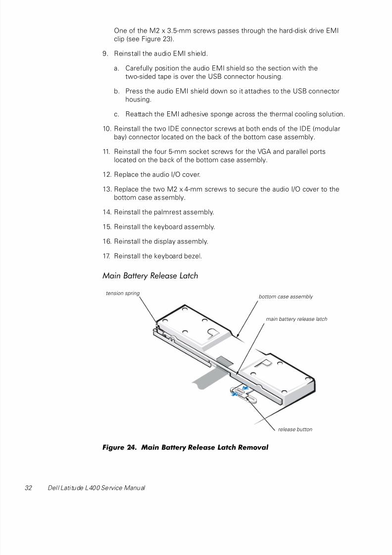
Main Battery Release Latch
Figure 24. Main Battery Release Latch Removal
main battery release latch
tension spring
release button
bottom case assembly

8/6/2019 Laptop Dell l 400
http://slidepdf.com/reader/full/laptop-dell-l-400 37/40
support.dell.com Dell Latitude L400 Service Manual 33
1. Remove the keyboard bezel.
2. Remove the display assembly.
3. Remove the keyboard.
4. Remove the palmrest assembly.
5. Remove the system board.
NOTICE: The tabs on the release button are plastic. Care should betaken when squeezing the tabs to avoid breaking them.
6. Using needle-nose pliers, gently squeeze the two tabs on the back of the
release button together and grasp the top of the battery release latch and
gently pull up to free it from the release button assembly (see Figure 24).
7. To remove the battery release latch, unhook the small tension spring
located on the metal post next to the hard-disk drive.
APR Docking Doors
1. Turn the computer upside down.
The APR docking doors should be at the top.
2. Carefully insert a small flat-blade screwdriver in the opening between the
door edges and the edge of the door opening on the right side.
There is a small slot at the right edge of the door opening to show where
the screwdriver is placed.
3. Gently push the screw driver against the right edge of the back door to
cause the door to bow up at their center.
4. Grasp the back door as it bows up while still pressing the door edge with
the screwdriver.
5. Carefully slip the right-edge hinge of the back door off its right hinge pin.
NOTICE: The doors are attached to each other by a tension spring atthe left end of the doors. Do not try to separate the doors from eachother. They must be removed together.
6. Gently push the screw driver against the right edge of the front door to
cause the door to bow up at their center.
7. Grasp the front door as it bows up while still pressing the door edge withthe screwdriver.
8. Carefully slip the right-edge hinge of the front door off its right hinge pin.
9. Grasping both doors together, carefully slip the left side of each door off
their left hinge pins.
8/6/2019 Laptop Dell l 400
http://slidepdf.com/reader/full/laptop-dell-l-400 38/40
34 Dell Latitude L400 Service Manual
To replace the APR docking doors, perform the following steps.
NOTE: On the under side of the doors, a small F is printed on the front door
and a small B is printed on the back door. As you hold the doors for installation,
the front door is near you, the back door is away from you, and the tension
spring is to the left.
1. Turn the computer upside down.
The APR connector door opening should be at the top.
2. Holding the two doors together at their right edges, insert the left hinges
of the doors (at the end with the tension spring) onto the left, front and
back hinge pins.
3. Carefully bow the doors in the center.
4. Slip the right hinge of the back door on to the right, back hinge pin.
5. Slip the right hinge of the front door on to the right, front hinge pin.
6. Release the doors so they set into place.

8/6/2019 Laptop Dell l 400
http://slidepdf.com/reader/full/laptop-dell-l-400 39/40
Index 1
Index
A
APR docking doors removal, 33
B
bottom assembly
components, 22
illustrated, 22
D
display assembly
bezel removal, 11
hinge removal, 15
latch removal, 12
removal, 9
F
fan removal, 25
field-replaceable parts and
assemblies illustrated, 6
Ggrounding to dissipate static
electricity, 3
H
hard-disk drive assembly removal, 7
hinge removal, 15
K
keyboard assembly removal, 16
L
latch removal, 12
LCD panel removal, 13
Mmain battery
release latch removal, 32
removal, 3, 23
memory module removal, 18
modem removal, 24
P
palmrest assembly removal, 19

8/6/2019 Laptop Dell l 400
http://slidepdf.com/reader/full/laptop-dell-l-400 40/40
R
reserve battery removal, 23
S
screw identification and tightening, 3
speaker removal, 27
system board assembly
removal, 29
T
tools, 2
touch pad removal, 21
Z
ZIF connectors, 5