Embed Size (px)
Citation preview
Large Eddy Simulation (LES) Applied to Low-Temperature and Diesel Engine Combustion Research
Joseph C. OefeleinSandia National Laboratories
Livermore, California 94551-9051
May 10, 2011
Support provided by the DOE EERE Vehicle Technologies Program is gratefully acknowledged
This presentation does not contain any proprietary, confidential, or otherwise restricted information
Project ID: ACE007

Overview
• Project provides fundamental research that supports advanced engine development
• Focused on next generation simulation capabilities using “capability class” computers
• Project scope, directions and continuation evaluated annually
• Two sets of barriers addressed– Development of clean high-efficiency
engines using hydrocarbon based fuels (petroleum and non-petroleum)
– LTC technologies (i.e., understanding effects of fuel-injection, ignition-timing, heat-transfer and engine-geometry on fuel-air mixing, combustion, soot, emissions over broad operating range)
– Requirements for efficient and routine use of high-performance (exascale) computers, development of predictive and affordable models for advanced engine combustion research
• Project funded by DOE/OVT: FY10 – $450KFY11 – $450K
Timeline
Budget
Barriers
• PI’s in the Engine Combustion Group at Sandia, Wisconsin, Penn State, Michigan, TU Darmstadt, GM (most recent)
• Project lead: Joe Oefelein
Partners
1
2
Relevance
Objective … maximize benefits of high performance computing for AEC research
• Apply unique capabilities that complement development of engineering models and codes– Advanced massively-parallel code framework– Access to full hierarchy of DOE computers– Direct coupling to key experiments
• Provide strong link between basic and applied research– Access to DOE Office of Science (OS) supercomputer facilities
• LBNL NERSC (www.nersc.gov)• ORNL NCCS (www.nccs.gov)• INCITE program
– Synergy between CRF OS-BES and EERE-VT programs
• Establish dedicated facilities, resources– Mid-scale computer clusters and storage– Enhanced collaborative interactions
( … Innovative and Novel Computational Impact on Theory and Experiment)
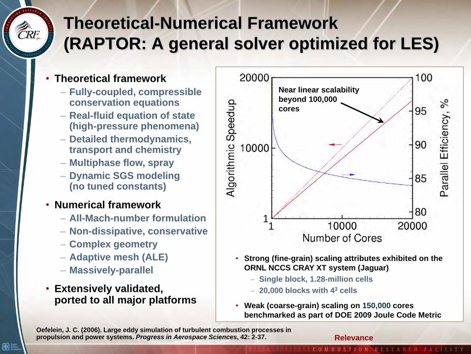
Theoretical-Numerical Framework (RAPTOR: A general solver optimized for LES)
• Theoretical framework– Fully-coupled, compressible
conservation equations– Real-fluid equation of state
(high-pressure phenomena)– Detailed thermodynamics,
transport and chemistry– Multiphase flow, spray – Dynamic SGS modeling
(no tuned constants)
• Numerical framework– All-Mach-number formulation– Non-dissipative, conservative– Complex geometry– Adaptive mesh (ALE)– Massively-parallel
• Extensively validated, ported to all major platforms
11
Near linear scalability beyond 100,000 cores
• Strong (fine-grain) scaling attributes exhibited on the ORNL NCCS CRAY XT system (Jaguar)
– Single block, 1.28-million cells– 20,000 blocks with 43 cells
• Weak (coarse-grain) scaling on 150,000 cores benchmarked as part of DOE 2009 Joule Code Metric
Oefelein, J. C. (2006). Large eddy simulation of turbulent combustion processes in propulsion and power systems. Progress in Aerospace Sciences, 42: 2-37. Relevance
Relevance
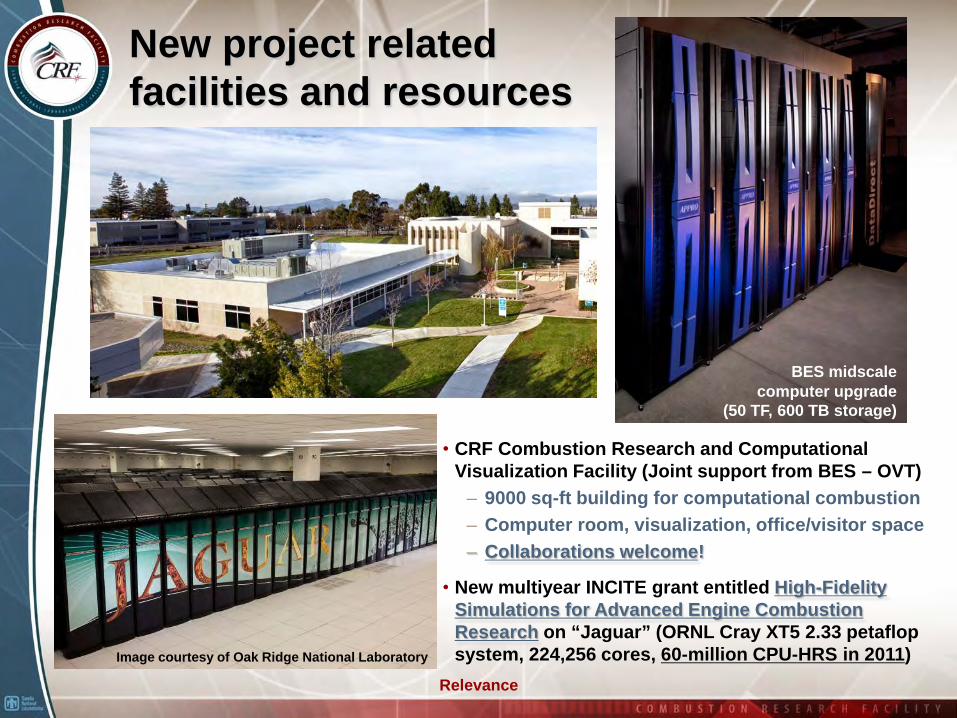
New project related facilities and resources
• CRF Combustion Research and Computational Visualization Facility (Joint support from BES – OVT)
– 9000 sq-ft building for computational combustion– Computer room, visualization, office/visitor space– Collaborations welcome!
• New multiyear INCITE grant entitled High-Fidelity Simulations for Advanced Engine Combustion Research on “Jaguar” (ORNL Cray XT5 2.33 petaflop system, 224,256 cores, 60-million CPU-HRS in 2011)
BES midscale computer upgrade
(50 TF, 600 TB storage)
Image courtesy of Oak Ridge National Laboratory
Approach
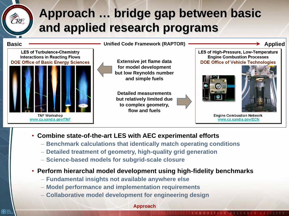
Approach … bridge gap between basic and applied research programs
Basic AppliedUnified Code Framework (RAPTOR)
Extensive jet flame data for model development
but low Reynolds number and simple fuels
Detailed measurements but relatively limited due
to complex geometry, flow and fuels
• Combine state-of-the-art LES with AEC experimental efforts– Benchmark calculations that identically match operating conditions– Detailed treatment of geometry, high-quality grid generation– Science-based models for subgrid-scale closure
• Perform hierarchal model development using high-fidelity benchmarks– Fundamental insights not available anywhere else– Model performance and implementation requirements– Collaborative model development for engineering design
Approach
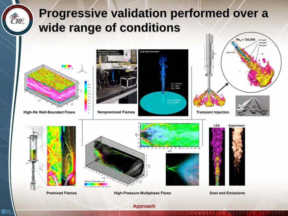
Progressive validation performed over a wide range of conditions
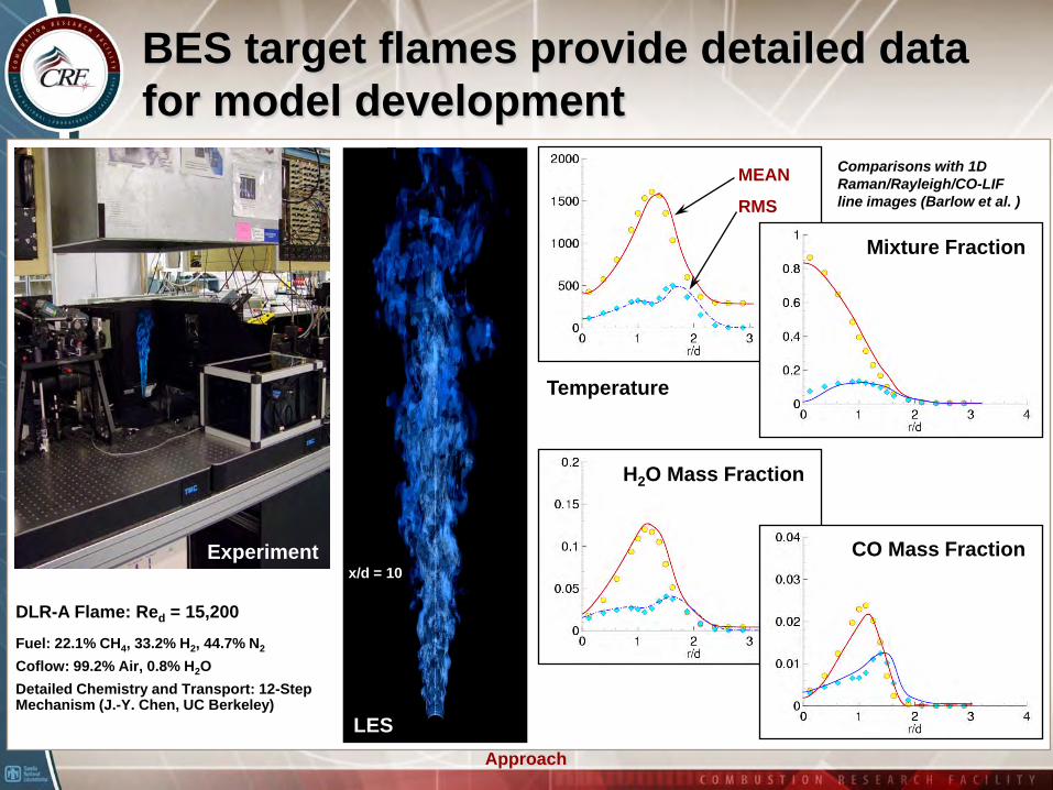
BES target flames provide detailed data for model development
DLR-A Flame: Red = 15,200
Fuel: 22.1% CH4, 33.2% H2, 44.7% N2
Coflow: 99.2% Air, 0.8% H2ODetailed Chemistry and Transport: 12-Step Mechanism (J.-Y. Chen, UC Berkeley)
Experiment
LES
x/d = 10
MEAN
RMS
Temperature
Mixture Fraction
Comparisons with 1D Raman/Rayleigh/CO-LIF line images (Barlow et al. )
H2O Mass Fraction
CO Mass Fraction
Approach
Accomplishments and Progress
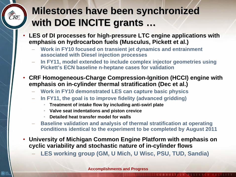
Milestones have been synchronized with DOE INCITE grants …
• LES of DI processes for high-pressure LTC engine applications with emphasis on hydrocarbon fuels (Musculus, Pickett et al.)
– Work in FY10 focused on transient jet dynamics and entrainment associated with Diesel injection processes
– In FY11, model extended to include complex injector geometries using Pickett’s ECN baseline n-heptane cases for validation
• CRF Homogeneous-Charge Compression-Ignition (HCCI) engine with emphasis on in-cylinder thermal stratification (Dec et al.)
– Work in FY10 demonstrated LES can capture basic physics– In FY11, the goal is to improve fidelity (advanced gridding)
• Treatment of intake flow by including anti-swirl plate• Valve seat indentations and piston crevice• Detailed heat transfer model for walls
– Baseline validation and analysis of thermal stratification at operating conditions identical to the experiment to be completed by August 2011
• University of Michigan Common Engine Platform with emphasis on cyclic variability and stochastic nature of in-cylinder flows– LES working group (GM, U Mich, U Wisc, PSU, TUD, Sandia)
Accomplishments and Progress
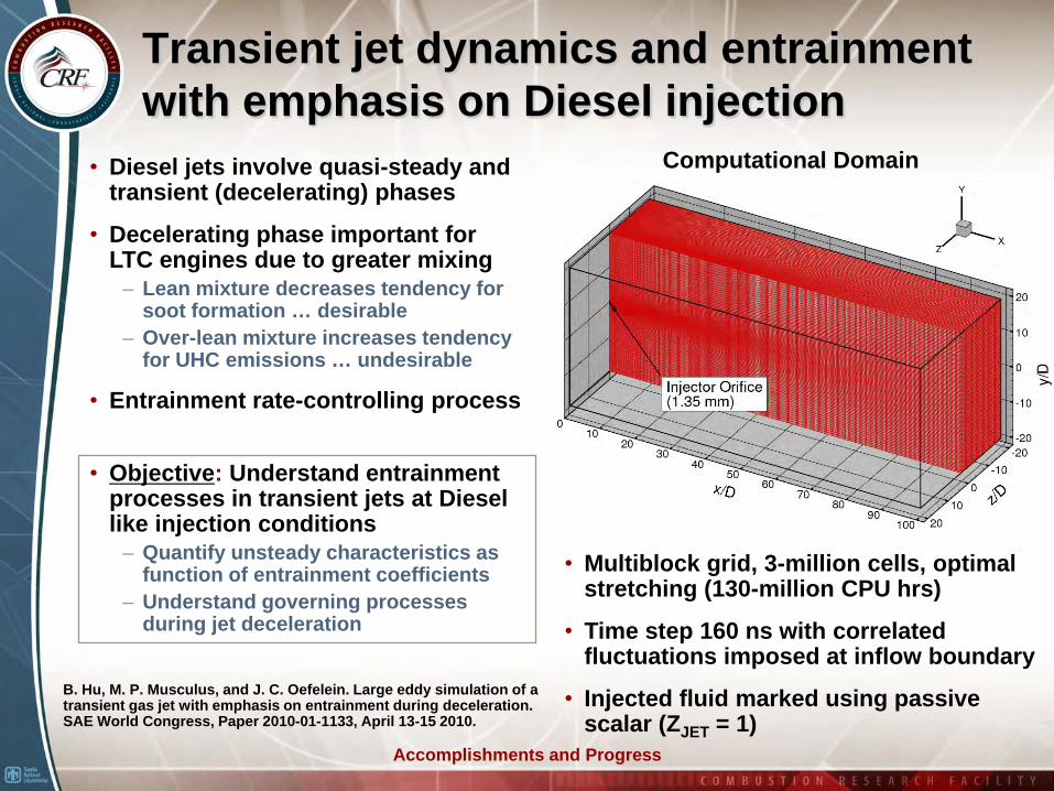
Transient jet dynamics and entrainment with emphasis on Diesel injection
• Diesel jets involve quasi-steady and transient (decelerating) phases
• Decelerating phase important for LTC engines due to greater mixing
– Lean mixture decreases tendency for soot formation … desirable
– Over-lean mixture increases tendency for UHC emissions … undesirable
• Entrainment rate-controlling process
• Objective: Understand entrainment processes in transient jets at Diesel like injection conditions
– Quantify unsteady characteristics as function of entrainment coefficients
– Understand governing processes during jet deceleration
B. Hu, M. P. Musculus, and J. C. Oefelein. Large eddy simulation of a transient gas jet with emphasis on entrainment during deceleration. SAE World Congress, Paper 2010-01-1133, April 13-15 2010.
Computational Domain
• Multiblock grid, 3-million cells, optimal stretching (130-million CPU hrs)
• Time step 160 ns with correlated fluctuations imposed at inflow boundary
• Injected fluid marked using passive scalar (ZJET = 1)
Accomplishments and Progress
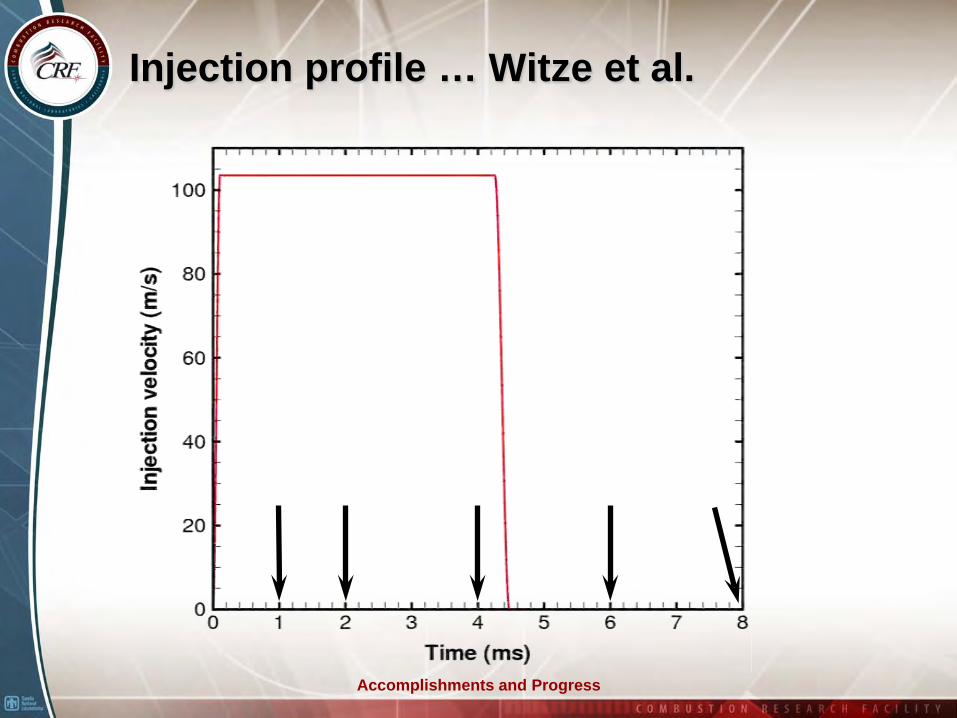
Injection profile … Witze et al.
Accomplishments and Progress
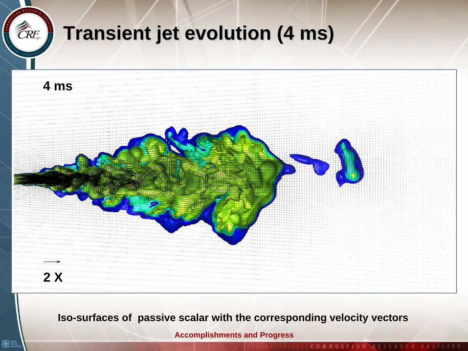
Transient jet evolution (4 ms)
Iso-surfaces of passive scalar with the corresponding velocity vectors
2 X
4 ms
Accomplishments and Progress
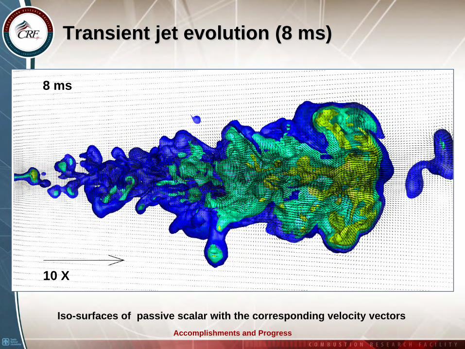
Transient jet evolution (8 ms)
Iso-surfaces of passive scalar with the corresponding velocity vectors
10 X
8 ms
Accomplishments and Progress
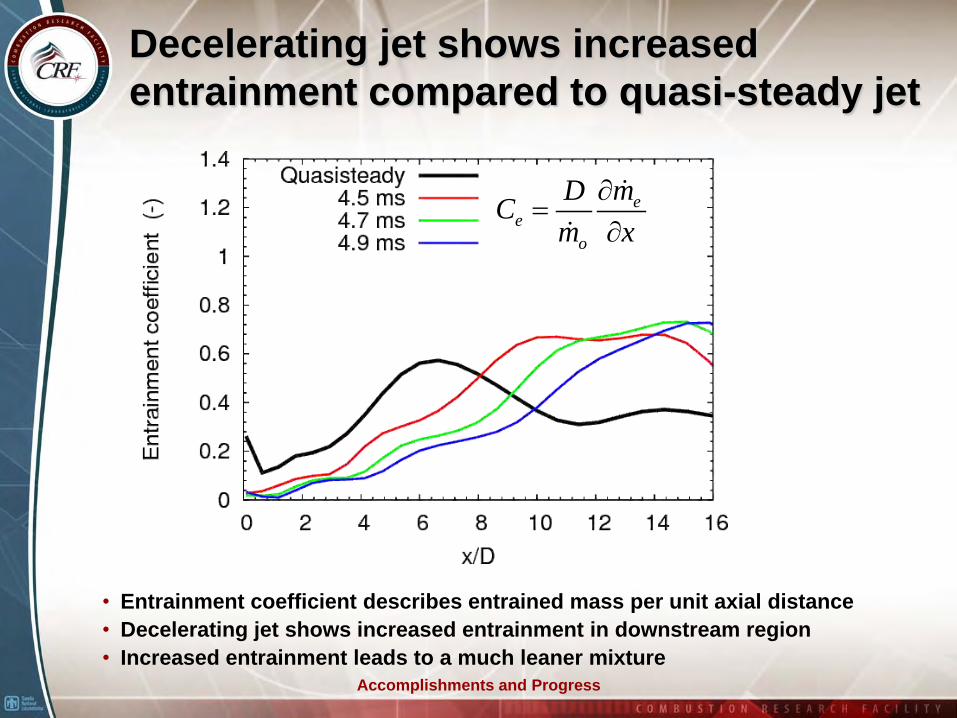
Decelerating jet shows increased entrainment compared to quasi-steady jet
ee
o
mDCm x
∂=
∂
• Entrainment coefficient describes entrained mass per unit axial distance• Decelerating jet shows increased entrainment in downstream region• Increased entrainment leads to a much leaner mixture
Accomplishments and Progress
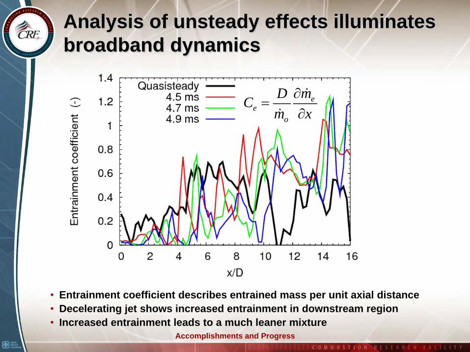
Analysis of unsteady effects illuminates broadband dynamics
• Entrainment coefficient describes entrained mass per unit axial distance• Decelerating jet shows increased entrainment in downstream region• Increased entrainment leads to a much leaner mixture
ee
o
mDCm x
∂=
∂
Accomplishments and Progress
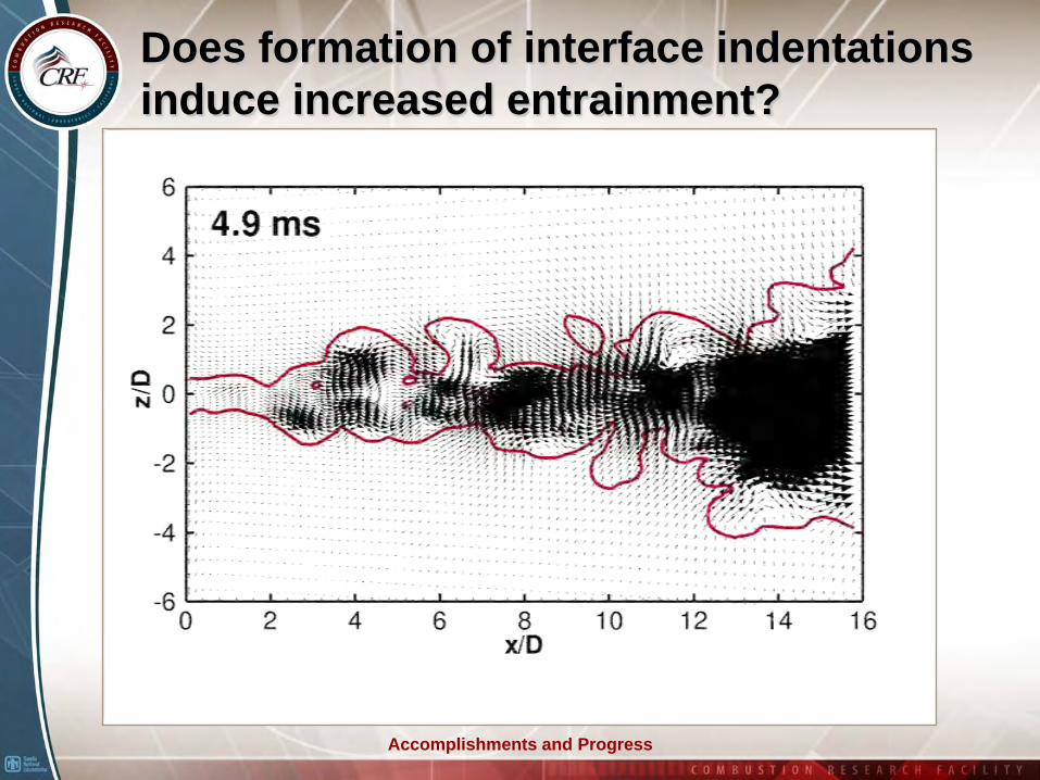
Does formation of interface indentations induce increased entrainment?
Accomplishments and Progress
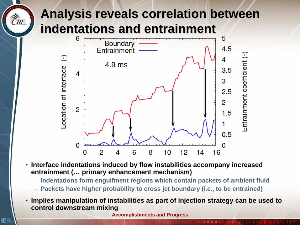
Analysis reveals correlation between indentations and entrainment
4.9 ms
• Interface indentations induced by flow instabilities accompany increased entrainment (… primary enhancement mechanism)
– Indentations form engulfment regions which contain packets of ambient fluid– Packets have higher probability to cross jet boundary (i.e., to be entrained)
• Implies manipulation of instabilities as part of injection strategy can be used to control downstream mixing
Accomplishments and Progress
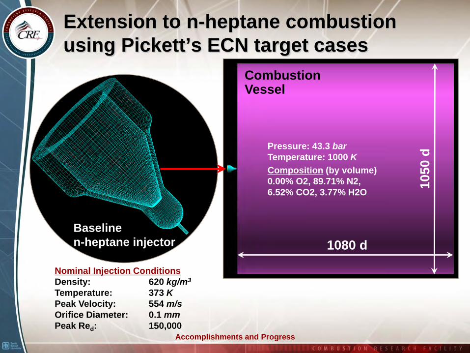
Extension to n-heptane combustion using Pickett’s ECN target cases
1080 d
1050
d
CombustionVessel
Baseline n-heptane injector
Pressure: 43.3 barTemperature: 1000 KComposition (by volume)0.00% O2, 89.71% N2, 6.52% CO2, 3.77% H2O
Nominal Injection ConditionsDensity: 620 kg/m3
Temperature: 373 KPeak Velocity: 554 m/sOrifice Diameter: 0.1 mmPeak Red: 150,000
Accomplishments and Progress
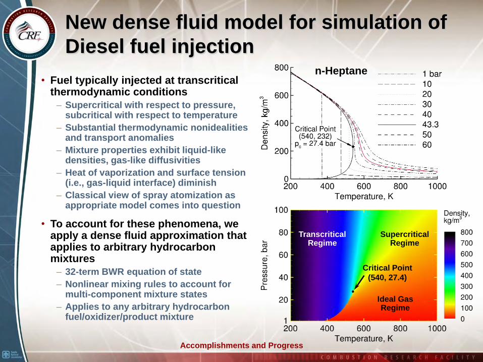
New dense fluid model for simulation of Diesel fuel injection
• Fuel typically injected at transcritical thermodynamic conditions
– Supercritical with respect to pressure, subcritical with respect to temperature
– Substantial thermodynamic nonidealities and transport anomalies
– Mixture properties exhibit liquid-like densities, gas-like diffusivities
– Heat of vaporization and surface tension (i.e., gas-liquid interface) diminish
– Classical view of spray atomization as appropriate model comes into question
• To account for these phenomena, we apply a dense fluid approximation that applies to arbitrary hydrocarbon mixtures
– 32-term BWR equation of state– Nonlinear mixing rules to account for
multi-component mixture states– Applies to any arbitrary hydrocarbon
fuel/oxidizer/product mixture
TranscriticalRegime
Critical Point(540, 27.4)
SupercriticalRegime
Ideal GasRegime
n-Heptane
Accomplishments and Progress
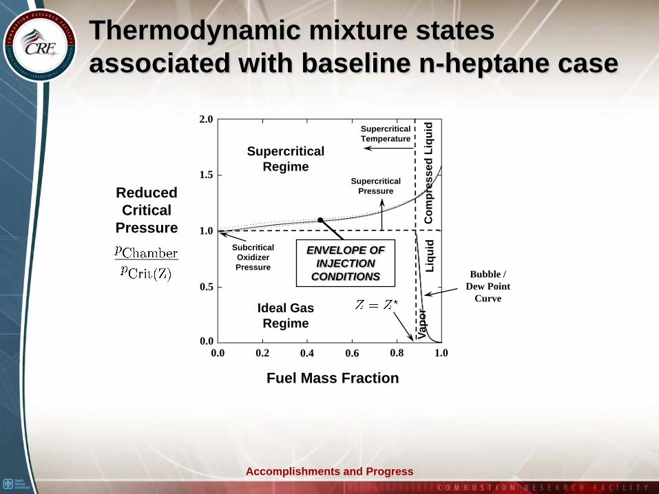
Thermodynamic mixture states associated with baseline n-heptane case
Supercritical Temperature
0.5
1.0
1.5
2.0
0.2 0.4 0.6 0.8 1.00.0
Subcritical Oxidizer Pressure
Reduced Critical
Pressure
Supercritical Pressure
Fuel Mass Fraction
SupercriticalRegime
Ideal GasRegime
Com
pres
sed
Liqu
idLi
quid
Vapo
r
Bubble / Dew Point
Curve
0.0
ENVELOPE OF INJECTION
CONDITIONS
Accomplishments and Progress
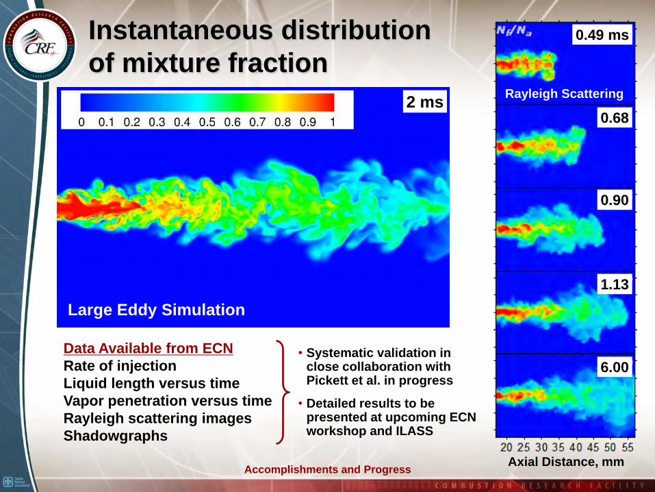
Instantaneous distribution of mixture fraction
0.49 ms
0.68
0.90
1.13
6.00
2 ms
Axial Distance, mm
Large Eddy Simulation
Rayleigh Scattering
Data Available from ECNRate of injectionLiquid length versus timeVapor penetration versus timeRayleigh scattering imagesShadowgraphs
• Systematic validation in close collaboration with Pickett et al. in progress
• Detailed results to be presented at upcoming ECN workshop and ILASS
Accomplishments and Progress
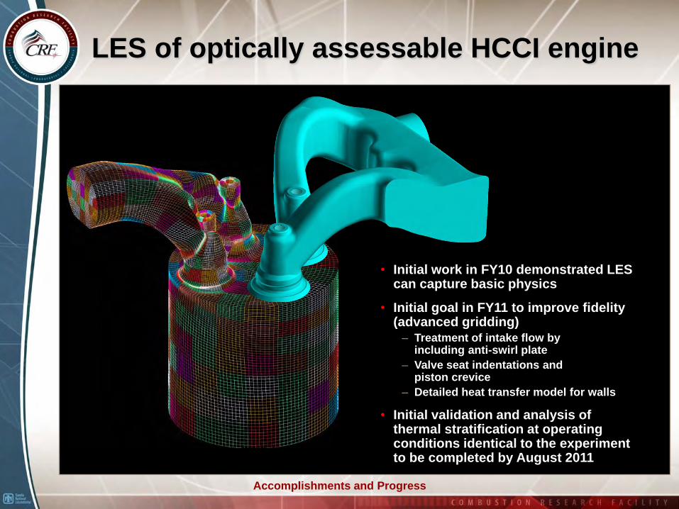
LES of optically assessable HCCI engine
• Initial work in FY10 demonstrated LES can capture basic physics
• Initial goal in FY11 to improve fidelity (advanced gridding)
– Treatment of intake flow by including anti-swirl plate
– Valve seat indentations and piston crevice
– Detailed heat transfer model for walls
• Initial validation and analysis of thermal stratification at operating conditions identical to the experiment to be completed by August 2011

Collaborations and Coordination
Collaborators ... special thanks to Dr. Bing Hu and Dr. Rainer Dahms
• CRF Departments 8351, 8353, 8362, 8367, 8963 (Barlow, Chen, Dec, Frank, Kerstein, Miles, Musculus, Najm, Pickett, Rouson, Settersten, Shaddix, Siebers, Steeper).
– 8353: Combustion Chemistry– 8362: Engine Combustion– 8367: Hydrogen & Combustion Technology– 8963: Scalable Modeling & Analysis
• Professor W. Anderson, Purdue University.• Professor J.-Y. Chen, University of California, Berkeley.• Professor J. Doom, Minnesota State University.• Professor A. Dreizler, Technical University of Darmstadt, Germany.• Professor B. Geurts, University of Twente, The Netherlands.• Professor D. Haworth, The Pennsylvania State University.• Professor J. Janika, Technical University of Darmstadt, Germany.• Professor A. Kempf, Duisburg-Essen University, Germany.• Professor T. Lieuwen, Georgia Institute of Technology.• Professor K. Mahesh, University of Minnesota.• Professor S. Menon, Georgia Institute of Technology.• Professor C. Merkle, Purdue University.• Professor M. Modest, University of California, Merced.• Professor C. Pantano, University of Illinois at Urbana-Champaign.• Professor T. Poinsot, CERFACS, France.• Professor S. Pope, Cornell University.• Professor C. Rutland, University of Wisconsin, Madison.• Professor R. Santoro, The Pennsylvania State University.• Professor V. Sick, University of Michigan.• Professor J. Sutton, Ohio State University.• Professor H. Wang, University of Southern California.• Professor V. Yang, Georgia Institute of Technology.
• Dr. J. Bell, Lawrence Berkeley National Laboratory.• Dr. J. Bellan, NASA Jet Propulsion Laboratory.• Dr. C. Carter, Air Force Research Laboratory, WPAFB, OH.• Dr. T. Drozda, Rolls Royce Aircraft Engines.• Dr. O. Haidn, The German Aerospace Center (DLR).• Dr. D. Kothe, Oak Ridge National Laboratory.• Dr. T.-W. Kuo, General Motors R&D Center.• Dr. M. Oschwald, The German Aerospace Center (DLR).• Dr. S. Rahman, NASA Stennis Space Center.• Dr. M. Roquemore, Air Force Research Laboratory, WPAFB, OH.• Dr. R. Sankaran, Oak Ridge National Laboratory.• Dr. V. Sankaran, United Technologies Research Center.• Dr. K. Tucker, NASA Marshall Space Flight Center.• Dr. D. Talley, Air Force Research Laboratory, EAFB, CA
• Postdoc’s and Students• Judith Segura, Stanford University, Dec 2000 – Sep 2004.• Tomasz Drozda, University of Pittsburgh, Oct 2005 – Oct 2008.• Victoria Lee, Cal. Polytechnic State University, Summer 2006, 2007.• Vaidyanathan Sankaran, Georgia Tech., Feb 2006 – Oct 2008.• Robert Knaus, UIUC, Summer 2007, 2008.• Joshua Smith, University of Adelaide, Australia, 2007.• Bing Hu, University of Wisconsin, Madison, Jan 2009 – Present.• Jeffrey Doom, University of Minnesota, Jan 2009 – Aug 2010.• Guilhem Lacaze, CERFACS, Toulouse France, Aug 2009 – Present.• Ville Vuorinen, Helsinki University of Technology, Finland, 2009.• Rainer Dahms, Aachen University, Germany, Jul 2010 – Present.• Matthieu Masquelet, Georgia Institute of Technology, 2011.• Raphael Mari, CERFACS, Toulouse France, Apr 2011 – Sep 2011.
*Names in red are Postdoctoral Appointees assigned to this project
Collaborations and Coordination
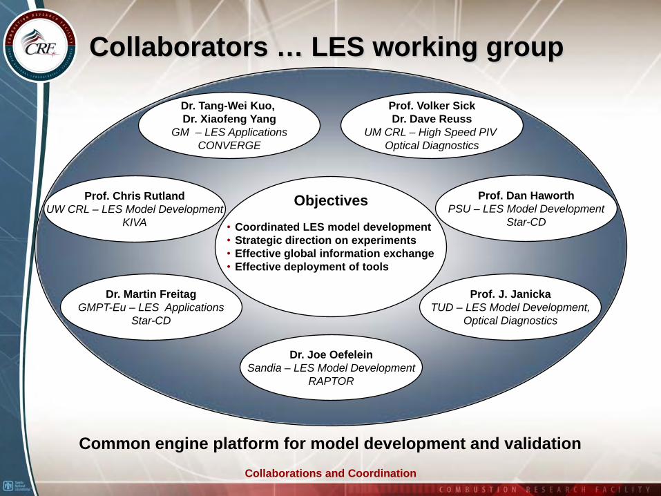
Collaborators … LES working group
• Coordinated LES model development• Strategic direction on experiments• Effective global information exchange• Effective deployment of tools
Objectives
Prof. Volker SickDr. Dave Reuss
UM CRL – High Speed PIV Optical Diagnostics
Dr. Tang-Wei Kuo, Dr. Xiaofeng Yang
GM – LES ApplicationsCONVERGE
Prof. Chris RutlandUW CRL – LES Model Development
KIVA
Dr. Joe OefeleinSandia – LES Model Development
RAPTOR
Prof. Dan HaworthPSU – LES Model Development
Star-CD
Prof. J. JanickaTUD – LES Model Development,
Optical Diagnostics
Dr. Martin FreitagGMPT-Eu – LES Applications
Star-CD
Common engine platform for model development and validation
Proposed Future Work
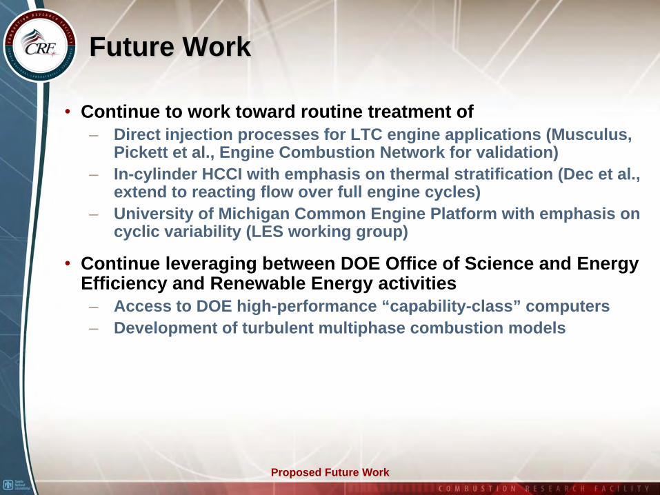
Future Work
• Continue to work toward routine treatment of– Direct injection processes for LTC engine applications (Musculus,
Pickett et al., Engine Combustion Network for validation)– In-cylinder HCCI with emphasis on thermal stratification (Dec et al.,
extend to reacting flow over full engine cycles)– University of Michigan Common Engine Platform with emphasis on
cyclic variability (LES working group)
• Continue leveraging between DOE Office of Science and Energy Efficiency and Renewable Energy activities– Access to DOE high-performance “capability-class” computers– Development of turbulent multiphase combustion models
Summary
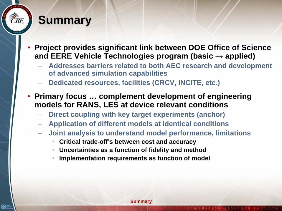
Summary
• Project provides significant link between DOE Office of Science and EERE Vehicle Technologies program (basic → applied)– Addresses barriers related to both AEC research and development
of advanced simulation capabilities– Dedicated resources, facilities (CRCV, INCITE, etc.)
• Primary focus … complement development of engineering models for RANS, LES at device relevant conditions– Direct coupling with key target experiments (anchor)– Application of different models at identical conditions– Joint analysis to understand model performance, limitations
• Critical trade-off’s between cost and accuracy• Uncertainties as a function of fidelity and method• Implementation requirements as function of model
Technical Back-Up Slides
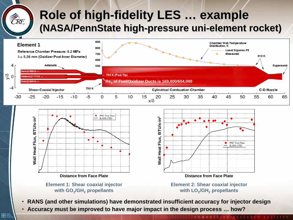
Role of high-fidelity LES … example (NASA/PennState high-pressure uni-element rocket)
Red of Fuel/Oxidizer Ducts is 169,000/604,000
Element 1
• RANS (and other simulations) have demonstrated insufficient accuracy for injector design• Accuracy must be improved to have major impact in the design process … how?
Element 1: Shear coaxial injector with GO2/GH2 propellants
Element 2: Shear coaxial injector with LO2/GH2 propellants
Wal
l Hea
t Flu
x, B
TU/s
-in2
Distance from Face Plate Distance from Face Plate
Wal
l Hea
t Flu
x, B
TU/s
-in2
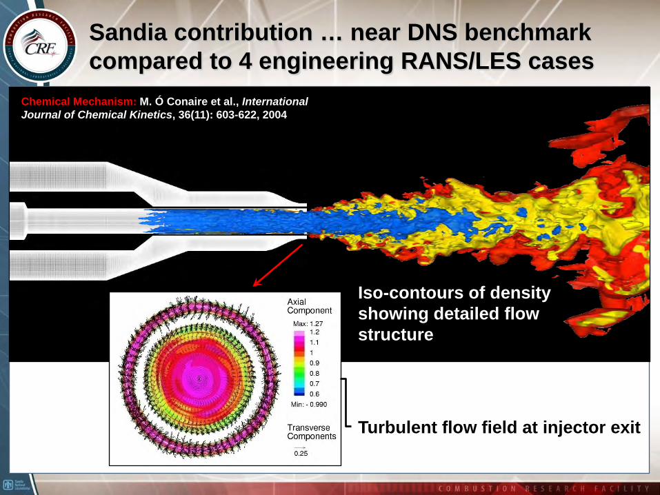
Sandia contribution … near DNS benchmark compared to 4 engineering RANS/LES cases
Turbulent flow field at injector exit
Iso-contours of density showing detailed flow structure
Chemical Mechanism: M. Ó Conaire et al., International Journal of Chemical Kinetics, 36(11): 603-622, 2004
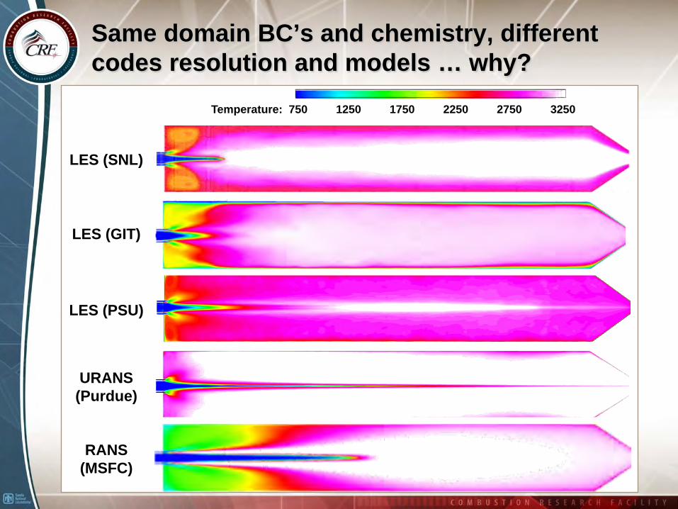
Same domain BC’s and chemistry, different codes resolution and models … why?
Temperature: 750 1250 1750 2250 2750 3250
LES (SNL)
LES (GIT)
LES (PSU)
URANS(Purdue)
RANS(MSFC)
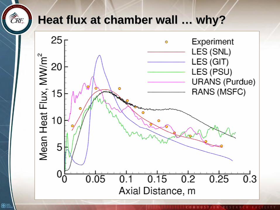
Heat flux at chamber wall … why?
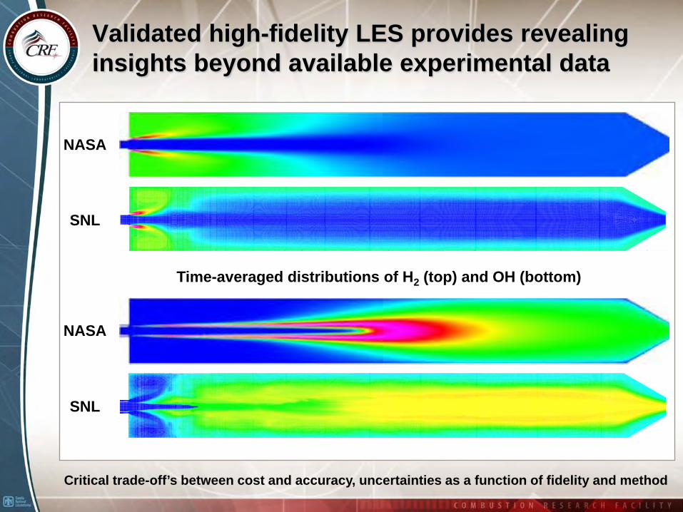
Validated high-fidelity LES provides revealing insights beyond available experimental data
NASA
SNL
NASA
SNL
Time-averaged distributions of H2 (top) and OH (bottom)
Critical trade-off’s between cost and accuracy, uncertainties as a function of fidelity and method