Embed Size (px)
Citation preview
Towards a Balanced Methodology in
European Hydraulic Research 7-1
7. LARGE-SCALE INVESTIGATIONS PERFORMED IN THE LARGE WAVE CHANNEL (GWK) BY EUROPEAN USER GROUPS
Joachim Grüne
Dipl.-Ing., Research & Operation Manager of Coastal Research Centre (Forschungszentrum Küste (FZK)), Merkurstraße 11, 30419 Hannover, email: [email protected]
Abstract
The COASTAL RESEARCH CENTRE (Forschungszentrum Küste - FZK) is supported by the European Commission (EC) within the "Access to Research Infrastructures"-action with two contracts in the 5th. EU-Framework for access to the major research facility LARGE WAVE CHANNEL (GWK). This paper gives an overview about the performance of these contracts.
7.1 Introduction
The access to the infrastructure LARGE WAVE CHANNEL (GWK) by European researchers is enabled through support by the 5th. Framework Programme of the European community (EU) within the action "Access to Research Infrastructures", which is a part of the programme "Improving Human Research Potential and the Socio - Economic Knowledge base".
The FZK got two contracts for the project "GWK large-scale tests" from the European commission (EC), which provides eligible research user groups from member states the EC and the associated states with 100% coverage of travel and subsistence costs as well as with free of charge access to the LARGE WAVE CHANNEL.
The research facility LARGE WAVE CHANNEL (GWK) is one of the largest facilities of its kind world wide (309 m long, 5 m wide, and 7 m deep). It is used for large-scale experiments on research topics related to Coastal and Ocean Engineering. In the past research has been performed on coastal structures (dikes, breakwaters, revetments etc.), offshore structures (cylinders, pipes etc.) and wave-induced sediment transport (dune erosion, shoreline protection etc.). Wave heights up to 2.0 m can be generated with a maximum water depth of 5 m. State-of-the-art wave generation and absorption control are available including irregular and freak wave generation. This also includes state-of-the-art measuring and recording instruments, data acquisition, and processing and analysis systems.
7.2 Project realisation
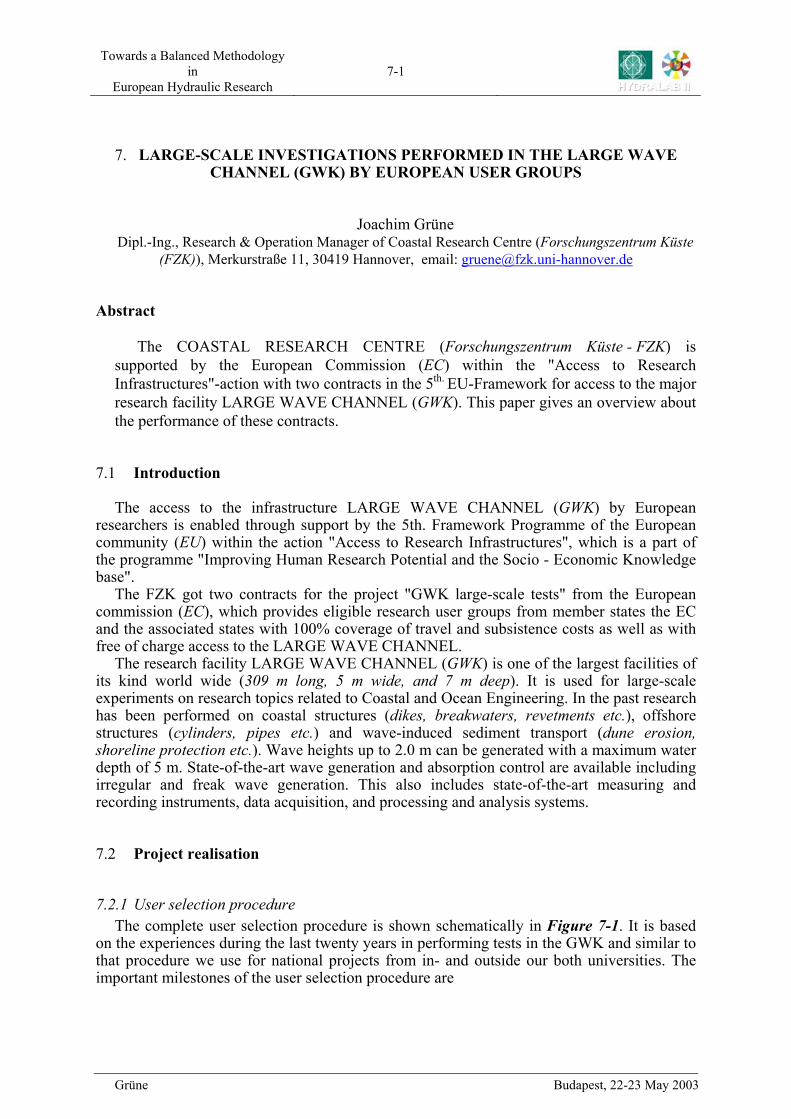
7.2.1 User selection procedure The complete user selection procedure is shown schematically in . It is based
on the experiences during the last twenty years in performing tests in the GWK and similar to that procedure we use for national projects from in- and outside our both universities. The important milestones of the user selection procedure are
Figure 7-1
Grüne Budapest, 22-23 May 2003
Towards a Balanced Methodology in
European Hydraulic Research 7-2
− the detailed feasibility check. It has been confirmed, that a successful evaluation
and test performance cannot be done without such a check, − the training course and − the final design of the model set-up and test procedure, where results from
preceding small-scale investigations and / or field investigations are an excellent tool for improving the design.
Figure 7-1. Scheme of user selection procedure
User Group Facility Provider
FINAL PROPOSAL
Review byUSER SELECTION PANEL
nega
tive
positive
EC forapprovalpositive
information ofuser group
preparation / fabrication of parts of model set - upsand measuring techniques (over some months)
access time with building of model set - ups andmeasuring techniques and
test series
Discussions on final model set -upand performance of tests
Visit of the facilityparticipating some days with an ongoing project
( training course )
Improving of model set - up
feasibility checkof model set-up
and test procedurenegative po
sitiv
e
ONE-PAGE-PROPOSAL
First sketch ofproposed model set-up
including test parameters
General informationson user rules/conditions
and user selectionprocedure
PROPOSALrejected
user-selection procedure3
negative positive
PROPOSALrejected
From long time experience in running the Large Wave Channel (GWK) it was found that
first time users mostly neither have a realistic impression about the extreme large dimensions nor the impact from these dimensions on the performance of test series in the GWK. Therefore we already are starting the support to the users from the Access Programme during the selection procedure.
Grüne Budapest, 22-23 May 2003
Towards a Balanced Methodology in
European Hydraulic Research 7-3
Having received a one-page-proposal from an access-interested user or user group, which
should describe the topics of the proposed investigations in the GWK, the first step is to give further detailed information about the access project and to ask for a first sketch of proposed model set-up including proposed values of wave parameters. This proposed first model set-up is used for our feasibility check, which is done with respect to technical feasibility of model set-up construction, wave generation and measuring techniques and further to minimise the access time by realistic configurations of test series (which maximise the priority of the access, if positive evaluated). If the check indicates necessary changes of the model set-up or some useful variations, in discussions we advise the potential users to improve the model set-up.
If the improved model set-up is acceptable with respect to the feasibility in the GWK, the user group should submit the final proposal, which will be reviewed by the User Selection Panel. The FZK uses the Joint Panel of the Research Infrastructure Co-operation Network HYDRALAB II which acts simultaneously for 4 partners of HYDRALAB II with EC supported infrastructures in the classic hydraulic fields. The actual User Selection Panel consists of 5 independent members, 3 members from the infrastructure providers and the 4 facility managers, but only in advisory capacity. The panel uses the general procedures and selection criteria of HYDRALAB II.
After positive evaluation and getting the approval from the EC we invite the users to visit the facility and to participate some days with an ongoing project. In this training course the users (mainly the researchers, which will be present during the tests) shall get acquainted with the facility. In this way they are rather well prepared at the beginning of their investigations in the GWK. Furthermore, during this visit discussions shall take place on final model set-up and performance of the tests.
7.3 Selected Projects
In total 7 projects have been selected for access in the GWK by the user selection panel, evaluated from in total 32 proposals. The users from all selected projects are first time users. All 7 projects were approved for access by the EC within the two ongoing access contracts. The access periods of the projects differ between 3 and 7 weeks, the mean access period is roughly 6 weeks.
The topics of the selected projects, the names of the user group leaders and their affiliation and country are listed in Table 1. The projects from the first contract, marked with light blue in Table 1, are completed; a short description is given in chapter 3. The first project from the second contract will start in June 2003.
The selected projects cover a good mixture of relevant topics in coastal engineering: − one offshore project, − three breakwater projects, where
o the first one is constructed as a normal rubble mound breakwater, o the second one as a low-crested and submerged one, o and the third one as a steep fronted one,
− two beach projects, where o one beach is build with course grained and mixed gravel fractions, o and the other one with fine sand fractions,
− one wave kinematics project, which deals with freak wave generation.
Grüne Budapest, 22-23 May 2003
Towards a Balanced Methodology in
European Hydraulic Research 7-4
Leader of User Group Organization
Country of Group Leader and
(participants) Topic of proposal
Contract HPRI – CT – 1999 – 00101 (Total access period : 150 days) M.J.
Sterndorff DHI Water &
Environment DK Wave Load on Offshore Platform Decks
G.N. Bullock
University of Plymouth UK Breaking Wave Impacts on
Steep Fronted Coastal Structures
H.F. Burcharth Aalborg University DK
(B, NO)
Use of Heavy Rock in Rubble Mound Breakwaters and
Seawalls
T. Coates Hydraulic Research Wallingford
UK (F, I)
Large-Scale Modelling of Coarse Grained Beaches
M. Calabrese University of Naples
I (DK, NL)
Low-Crested and Submerged Breakwater in Presence of
Broken Waves Contract HPRI – CT – 2000 – 00157 (Total access period : 50 days)
S. Massel Institute of Oceanology, PAS PL (NO)
Run-up of Waves on Beaches and Induced Infiltration in the
Beach Body
L. Shemer Tel-Aviv University IL
Experimental Study of Extremely Steep (Freak) Waves
in a Tank
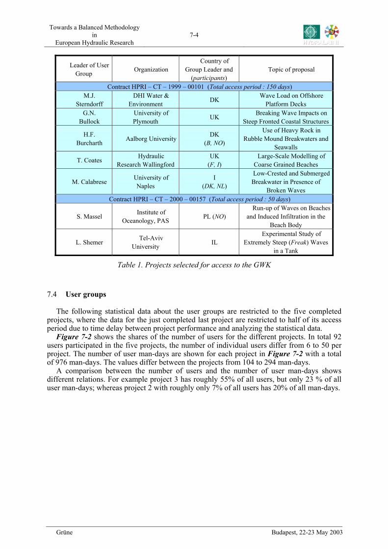
Table 1. Projects selected for access to the GWK
7.4 User groups
The following statistical data about the user groups are restricted to the five completed projects, where the data for the just completed last project are restricted to half of its access period due to time delay between project performance and analyzing the statistical data.
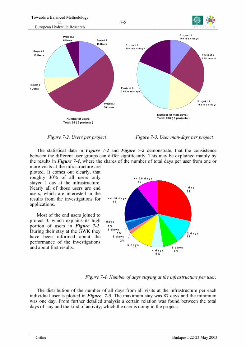
Figure 7-2
Figure 7-2
shows the shares of the number of users for the different projects. In total 92 users participated in the five projects, the number of individual users differ from 6 to 50 per project. The number of user man-days are shown for each project in with a total of 976 man-days. The values differ between the projects from 104 to 294 man-days.
A comparison between the number of users and the number of user man-days shows different relations. For example project 3 has roughly 55% of all users, but only 23 % of all user man-days; whereas project 2 with roughly only 7% of all users has 20% of all man-days.
Grüne Budapest, 22-23 May 2003
Towards a Balanced Methodology in
European Hydraulic Research 7-5
Grüne Budapest, 22-23 May 2003
Number of users: Total: 92 ( 5 projects )
Project 2 6 Users
Project 3 50 Users
Project 1 13 Users
Project 6 18 Users
Project 5 7 Users
P r o je c t 21 8 4 m a n -
P r o je c t 62 9 4 m a n -d a y
Number of man-days: Total: 976 ( 5 projects )
d a y s
P r o je k t 51 6 6 m a n -d a y
s
P r o je c t 11 0 4 m a n -d a y s
P r o je c t 32 2 8 m a n -d
s
Figure 7-2. Users per project Figure 7-3. User man-days per project
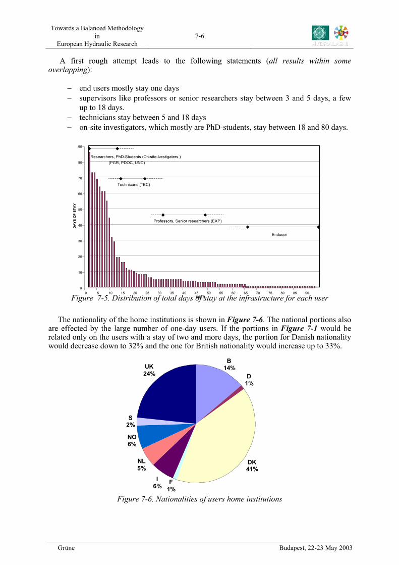
Figure 7-2 Figure 7-2 The statistical data in and demonstrate, that the consistence
between the different user groups can differ significantly. This may be explained mainly by the results in , where the shares of the number of total days per user from one or more visits at the infrastructure are plotted. It comes out clearly, that roughly 30% of all users only stayed 1 day at the infrastructure. Nearly all of those users are end users, which are interested in the results from the investigations for applications.
Figure 7-4
Figure 7-4. Number of days staying at the infrastructure per user.
> = 2 0 d a y s1 0%
> = 1 0 d a y s1 8%
d a y s1 %8 d a y s
4 %6 d a y s
2 %5 d a y s
1 1% 4 d a y s
6 %
3 d a y s 8 %
2 d a y s 1 1%
1 d a y 2 9%
Most of the end users joined to
project 3, which explains its high portion of users in . During their stay at the GWK they have been informed about the performance of the investigations and about first results.
9
Figure 7-1
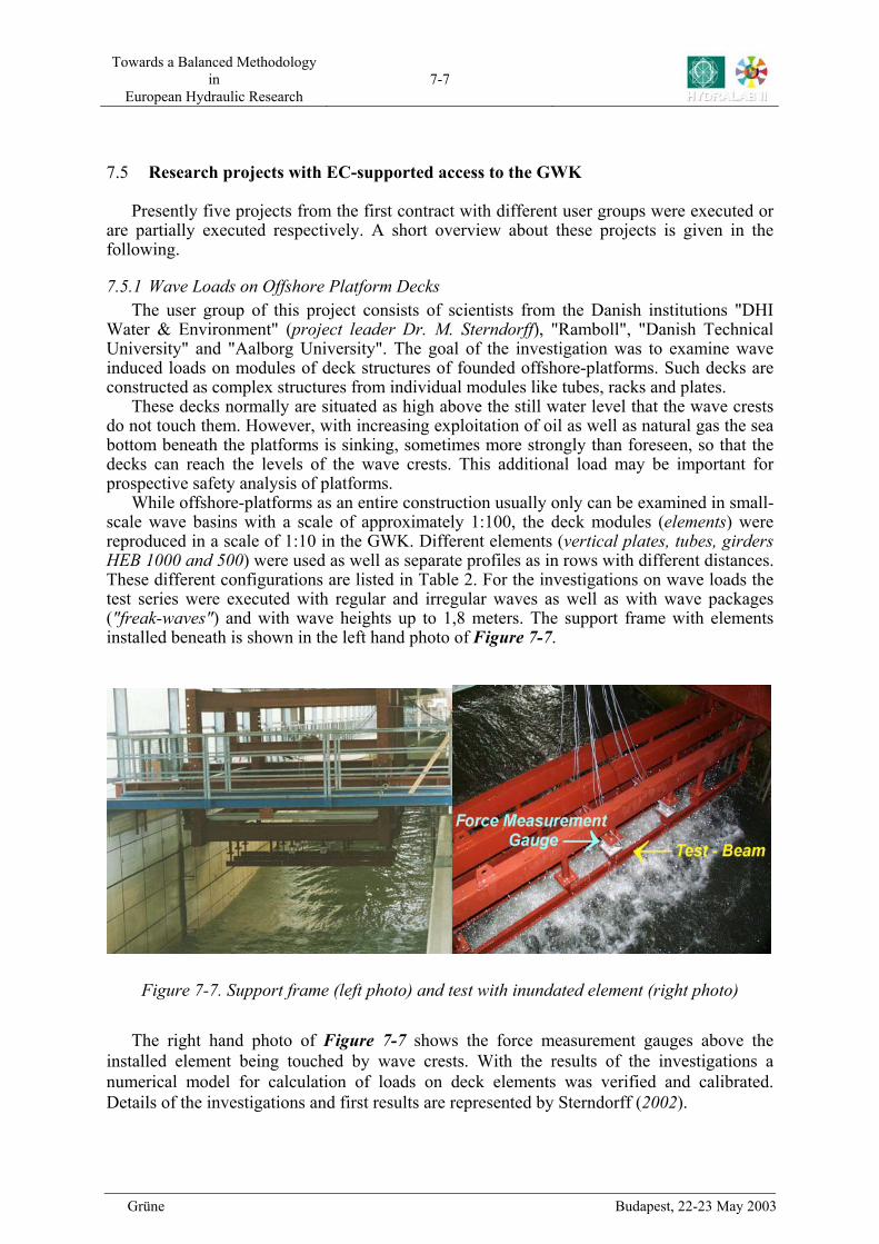
The distribution of the number of all days from all visits at the infrastructure per each
individual user is plotted in . The maximum stay was 87 days and the minimum was one day. From further detailed analysis a certain relation was found between the total days of stay and the kind of activity, which the user is doing in the project.
Figure 7-5
Towards a Balanced Methodology in
European Hydraulic Research 7-6
A first rough attempt leads to the following statements (all results within some
overlapping): − end users mostly stay one days − supervisors like professors or senior researchers stay between 3 and 5 days, a few
up to 18 days. − technicians stay between 5 and 18 days − on-site investigators, which mostly are PhD-students, stay between 18 and 80 days.
Figure 7-5. Distribution of total days of stay at the infrastructure for each user 0 5 10 15 20 25 30 35 40 45 50 55 60 65 70 75 80 85 90
U
0
10
20
30
40
50
60
70
80
90
DA
YS O
F ST
AY
SER
Researchers, PhD-Students (On-site-Ivestigaters.)
Technicans (TEC)
Professors, Senior researchers (EXP)
Enduser
(PGR, PDOC, UND)
The nationality of the home institutions is shown in . The national portions also
are effected by the large number of one-day users. If the portions in would be related only on the users with a stay of two and more days, the portion for Danish nationality would decrease down to 32% and the one for British nationality would increase up to 33%.
Figure 7-6
Figure 7-6. Nationalities of users home institutions
Figure 7-1
D1%
DK 41%
I 6%
NL 5%
NO 6%
S 2%
UK 24%
B14%
F1%
Grüne Budapest, 22-23 May 2003
Towards a Balanced Methodology in
European Hydraulic Research 7-7
7.5 Research projects with EC-supported access to the GWK
Presently five projects from the first contract with different user groups were executed or are partially executed respectively. A short overview about these projects is given in the following.
7.5.1 Wave Loads on Offshore Platform Decks The user group of this project consists of scientists from the Danish institutions "DHI
Water & Environment" (project leader Dr. M. Sterndorff), "Ramboll", "Danish Technical University" and "Aalborg University". The goal of the investigation was to examine wave induced loads on modules of deck structures of founded offshore-platforms. Such decks are constructed as complex structures from individual modules like tubes, racks and plates.
These decks normally are situated as high above the still water level that the wave crests do not touch them. However, with increasing exploitation of oil as well as natural gas the sea bottom beneath the platforms is sinking, sometimes more strongly than foreseen, so that the decks can reach the levels of the wave crests. This additional load may be important for prospective safety analysis of platforms.
While offshore-platforms as an entire construction usually only can be examined in small-scale wave basins with a scale of approximately 1:100, the deck modules (elements) were reproduced in a scale of 1:10 in the GWK. Different elements (vertical plates, tubes, girders HEB 1000 and 500) were used as well as separate profiles as in rows with different distances. These different configurations are listed in Table 2. For the investigations on wave loads the test series were executed with regular and irregular waves as well as with wave packages ("freak-waves") and with wave heights up to 1,8 meters. The support frame with elements installed beneath is shown in the left hand photo of . Figure 7-7
Figure 7-7. Support frame (left photo) and test with inundated element (right photo)
Figure 7-7
The right hand photo of shows the force measurement gauges above the
installed element being touched by wave crests. With the results of the investigations a numerical model for calculation of loads on deck elements was verified and calibrated. Details of the investigations and first results are represented by Sterndorff (2002).
Grüne Budapest, 22-23 May 2003
Towards a Balanced Methodology in
European Hydraulic Research 7-8
Configuration No.
Element Type No of
Beams Configuration
Distance [mm]
Wave Direction
[°] 1 Plate Profile 1 I - 90 2 Plate Profile 2 I I 200 90 3 Plate Profile 2 I I 300 90 4 Plate Profile 3 I I I 300 90 5 Plate Profile 3 I I I 600 90 6 HEB 1000 3 I I I 600 90 7 HEB 1000 3 I I I 300 90 8 Tubular 2 O O 300 90 9 Tubular 2 O O 294 76.8
10 2 HEB1000 & 3 HEB500 5 I I I I I 200 0 11 Configuration 10 & deck 5 I I I I I 200 0
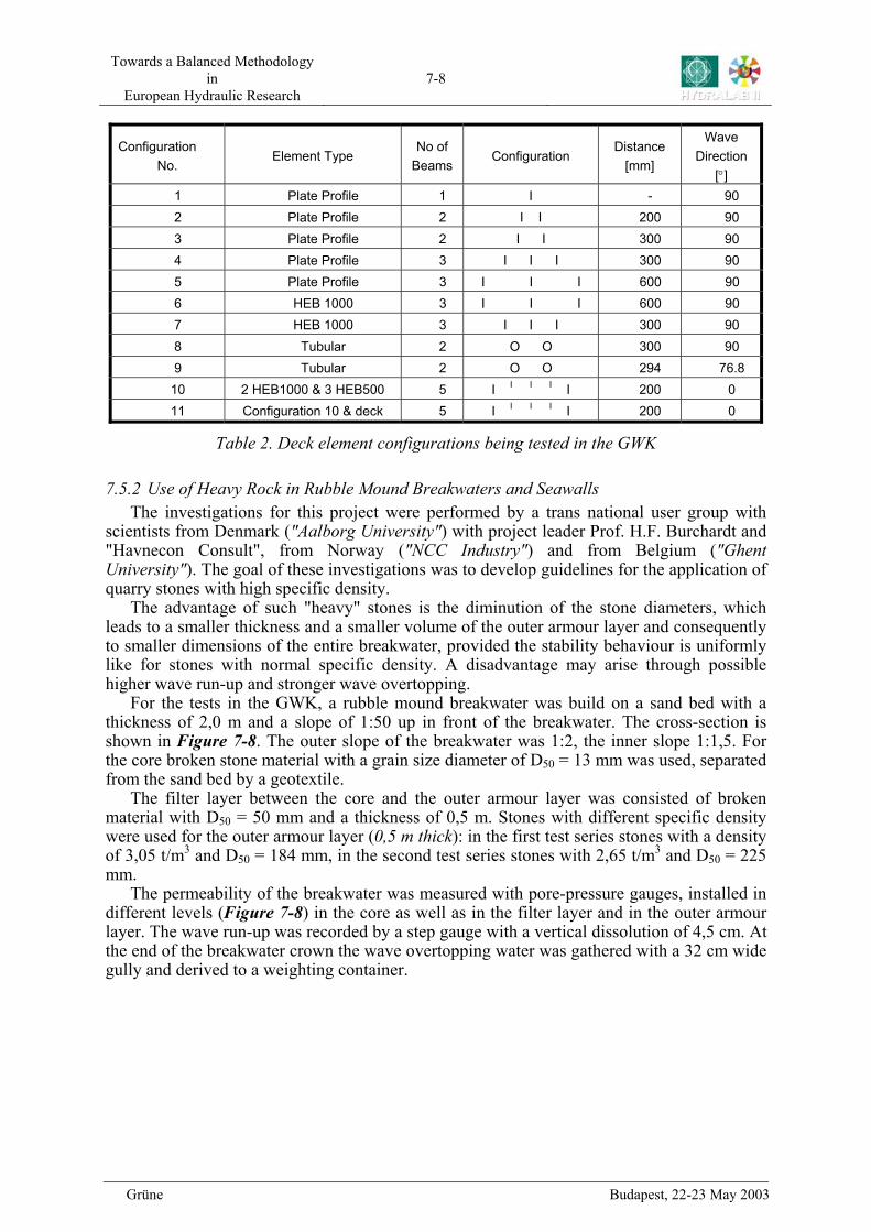
Table 2. Deck element configurations being tested in the GWK
7.5.2 Use of Heavy Rock in Rubble Mound Breakwaters and Seawalls The investigations for this project were performed by a trans national user group with
scientists from Denmark ("Aalborg University") with project leader Prof. H.F. Burchardt and "Havnecon Consult", from Norway ("NCC Industry") and from Belgium ("Ghent University"). The goal of these investigations was to develop guidelines for the application of quarry stones with high specific density.
The advantage of such "heavy" stones is the diminution of the stone diameters, which leads to a smaller thickness and a smaller volume of the outer armour layer and consequently to smaller dimensions of the entire breakwater, provided the stability behaviour is uniformly like for stones with normal specific density. A disadvantage may arise through possible higher wave run-up and stronger wave overtopping.
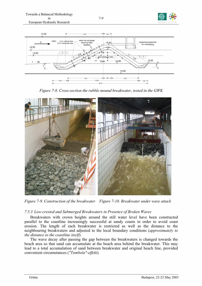
For the tests in the GWK, a rubble mound breakwater was build on a sand bed with a thickness of 2,0 m and a slope of 1:50 up in front of the breakwater. The cross-section is shown in . The outer slope of the breakwater was 1:2, the inner slope 1:1,5. For the core broken stone material with a grain size diameter of D50 = 13 mm was used, separated from the sand bed by a geotextile.
Figure 7-8
Figure 7-8
The filter layer between the core and the outer armour layer was consisted of broken material with D50 = 50 mm and a thickness of 0,5 m. Stones with different specific density were used for the outer armour layer (0,5 m thick): in the first test series stones with a density of 3,05 t/m3 and D50 = 184 mm, in the second test series stones with 2,65 t/m3 and D50 = 225 mm.
The permeability of the breakwater was measured with pore-pressure gauges, installed in different levels ( ) in the core as well as in the filter layer and in the outer armour layer. The wave run-up was recorded by a step gauge with a vertical dissolution of 4,5 cm. At the end of the breakwater crown the wave overtopping water was gathered with a 32 cm wide gully and derived to a weighting container.
Grüne Budapest, 22-23 May 2003
Towards a Balanced Methodology in
European Hydraulic Research 7-9
1,60
0,50
1 : 50
1 : 2,0 1 : 1,5
Core
7,40
0,45
+3,50
+4,50
+5,50
+7,00
+2,00
+0,00
1 : 1
1 : 1
0,80
1,10
3,007,00 1,60 5,30
+2,00
+4,55
C
13,90
18,75
0,95
1,80
measuring equipmentfor overtopping
pore pressure cells
wave run-up gauge(fixed by steel
neadles)
GRID : 1,0 m vertical lines0,5 m horizontal lines
Figure 7-8. Cross-section the rubble mound breakwater, tested in the GWK
Figure 7-9. Construction of the breakwater Figure 7-10. Breakwater under wave attack
7.5.3 Low-crested and Submerged Breakwaters in Presence of Broken Waves Breakwaters with crown heights around the still water level have been constructed
parallel to the coastline increasingly successful at sandy coasts in order to avoid coast erosion. The length of each breakwater is restricted as well as the distance to the neighbouring breakwaters and adjusted to the local boundary conditions (approximately to the distance to the coastline itself).
The wave decay after passing the gap between the breakwaters is changed towards the beach area so that sand can accumulate at the beach area behind the breakwater. This may lead to a total accumulation of sand between breakwater and original beach line, provided convenient circumstances ("Tombola"-effekt).
Grüne Budapest, 22-23 May 2003
Towards a Balanced Methodology in
European Hydraulic Research 7-10
This project was executed by a trans national user group from Italy ("Universities of
Naples I - II" with project leader Prof. Calabrese), from the Netherlands ("Infram") and from Denmark ("Aalborg University") and the results of this project should enable a more exact forecast of the effectiveness of such breakwaters, especially under sea state conditions with breaking waves.
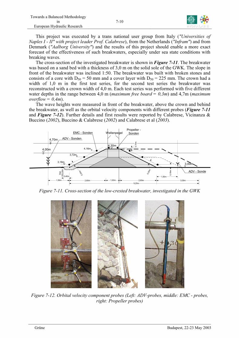
The cross-section of the investigated breakwater is shown in . The breakwater was based on a sand bed with a thickness of 3,0 m on the solid sole of the GWK. The slope in front of the breakwater was inclined 1:50. The breakwater was built with broken stones and consists of a core with D50 = 50 mm and a cover layer with D50 = 225 mm. The crown had a width of 1,0 m in the first test series, for the second test series the breakwater was reconstructed with a crown width of 4,0 m. Each test series was performed with five different water depths in the range between 4,0 m (maximum free board = 0,3m) and 4,7m (maximum overflow = 0,4m).
Figure 7-11
Figure 7-11
Figure 7-11. Cross-section of the low-crested breakwater, investigated in the GWK
The wave heights were measured in front of the breakwater, above the crown and behind the breakwater, as well as the orbital velocity components with different probes ( and ). Further details and first results were reported by Calabrese, Vicinanza & Buccino (2002), Buccino & Calabrese (2002) and Calabrese et al (2003).
Figure 7-12
Figure 7-12. Orbital velocity component probes (Left: ADV-probes, middle: EMC - probes, right: Propeller probes)
9,20m
2,60m 1,00m 2,60m 3,00m
4,30m
3,00m
0,40m
Stat
.22
5,30
m
4,00m
4,70m
0,20
m
Wellenpegel0,
10m
0,20
m
Propeller -Sonden
0,18
m
3,18m
3,72m
4,16m
EMC - Sonden
1,50m
1,50m
ADV - Sonden
ADV - Sonde
Grüne Budapest, 22-23 May 2003
Towards a Balanced Methodology in
European Hydraulic Research 7-11
7.5.4 Large-Scale Modelling of Coarse Grained Beaches
There are a large number of beaches worldwide, which consist of gravel or gravel-sand mixtures. The knowledge about the response of such beaches due to wave attack is poor, especially that for beaches with gravel-sand mixtures. Small-scale investigations were executed with gravel beaches, nevertheless such beaches, especially with gravel-sand mixtures, cannot be reproduced sufficiently in a small-scale model.
The goal of this project was to investigate the behaviour of beaches with gravel and gravel-sand mixtures with comparative large-scale test series in the GWK under same boundary conditions (identical slopes and wave climate). The user group consists of scientists from Great Britain ("HR Wallingford" with project leader T. Coates, "Imperial College London", "University of Plymouth" and "New Forest District"), from France ("University of Caen") and from Italy ("Universita di Firence"), which partially already have cooperated in a national British project for investigations in the field and in small-scale models on this topic.
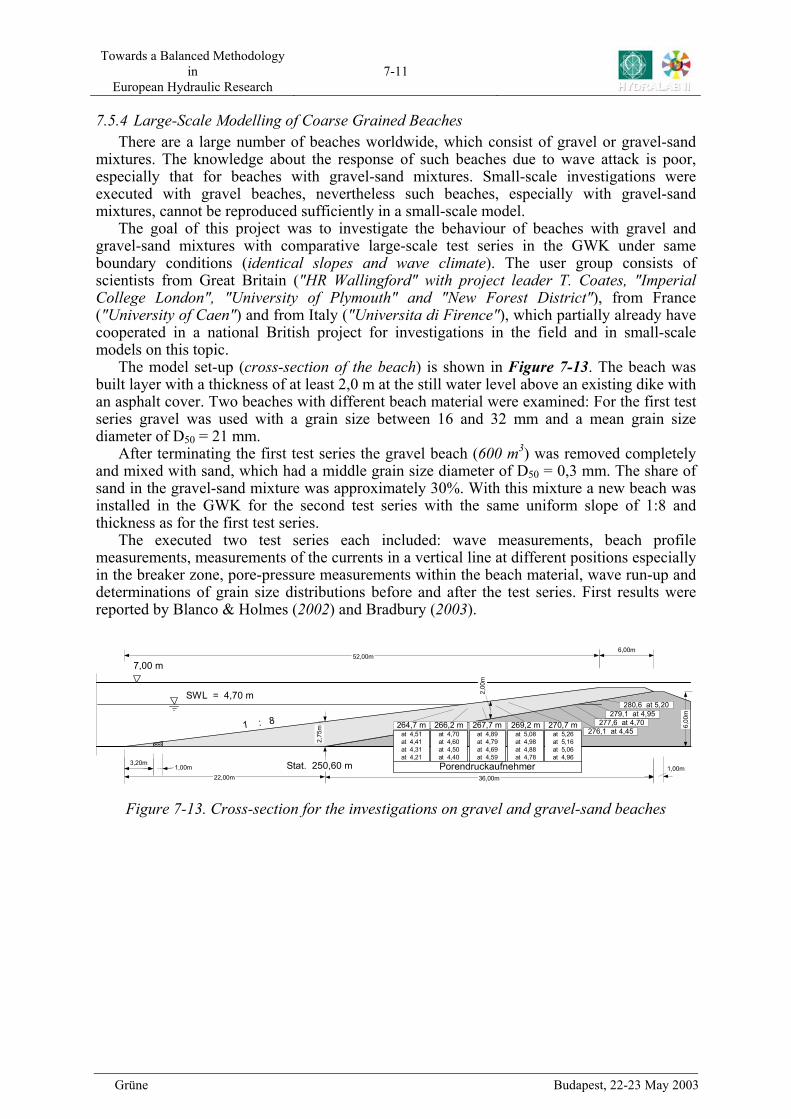
The model set-up (cross-section of the beach) is shown in . The beach was built layer with a thickness of at least 2,0 m at the still water level above an existing dike with an asphalt cover. Two beaches with different beach material were examined: For the first test series gravel was used with a grain size between 16 and 32 mm and a mean grain size diameter of D50 = 21 mm.
Figure 7-13
Figure 7-13. Cross-section for the investigations on gravel and gravel-sand beaches
After terminating the first test series the gravel beach (600 m3) was removed completely and mixed with sand, which had a middle grain size diameter of D50 = 0,3 mm. The share of sand in the gravel-sand mixture was approximately 30%. With this mixture a new beach was installed in the GWK for the second test series with the same uniform slope of 1:8 and thickness as for the first test series.
The executed two test series each included: wave measurements, beach profile measurements, measurements of the currents in a vertical line at different positions especially in the breaker zone, pore-pressure measurements within the beach material, wave run-up and determinations of grain size distributions before and after the test series. First results were reported by Blanco & Holmes (2002) and Bradbury (2003).
36,00m
6,00
m
1,00m22,00m
52,00m
1 : 8
2,00
m
2,75
m
Stat. 250,60 m3,20m1,00m
7,00 m
SWL = 4,70 m
264,7 mat 4,51at 4,41at 4,31at 4,21
266,2 mat 4,70at 4,60at 4,50at 4,40
269,2 mat 5,08at 4,98at 4,88at 4,78
270,7 mat 5,26at 5,16at 5,06at 4,96
Porendruckaufnehmer
276,1 at 4,45277,6 at 4,70
279,1 at 4,95280,6 at 5,20
267,7 mat 4,89at 4,79at 4,69at 4,59
6,00m
Grüne Budapest, 22-23 May 2003
Towards a Balanced Methodology in
European Hydraulic Research 7-12
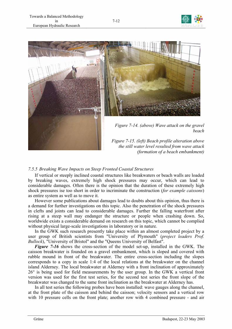
Figure 7-14. (above) Wave attack on the gravel beach
Figure 7-15. (left) Beach profile alteration above the still water level resulted from wave attack
(formation of a beach embankment)
7.5.5 Breaking Wave Impacts on Steep Fronted Coastal Structures If vertical or steeply inclined coastal structures like breakwaters or beach walls are loaded
by breaking waves, extremely high shock pressures may occur, which can lead to considerable damages. Often there is the opinion that the duration of these extremely high shock pressures ise too short in order to incriminate the construction (for example caissons) as entire system as well as to move it.
However some publications about damages lead to doubts about this opinion, thus there is a demand for further investigations on this topic. Also the penetration of the shock pressures in clefts and joints can lead to considerable damages. Further the falling waterfront after rising at a steep wall may endanger the structure or people when crashing down. So, worldwide exists a considerable demand on research on this topic, which cannot be complied without physical large-scale investigations in laboratory or in nature.
In the GWK such research presently take place within an almost completed project by a user group of British scientists from "University of Plymouth" (project leaders Prof. Bullock), "University of Bristol" and the "Queens University of Belfast".
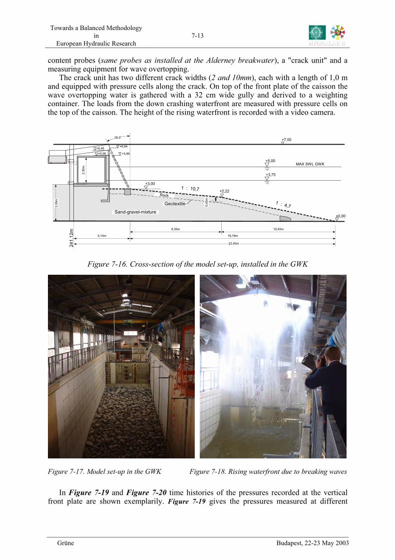
Figure 7-16 shows the cross-section of the model set-up, installed in the GWK. The caisson breakwater is founded on a gravel embankment, which is sloped and covered with rubble mound in front of the breakwater. The entire cross-section including the slopes corresponds to a copy in scale 1:4 of the local relations at the breakwater on the channel island Alderney. The local breakwater at Alderney with a front inclination of approximately 26° is being used for field measurements by the user group. In the GWK a vertical front version was used for the first test series, for the second test series the front slope of the breakwater was changed to the same front inclination as the breakwater at Alderney has.
In all test series the following probes have been installed: wave gauges along the channel, at the front plate of the caisson and behind the caisson; velocity sensors and a vertical row with 10 pressure cells on the front plate; another row with 4 combined pressure - and air
Grüne Budapest, 22-23 May 2003
Towards a Balanced Methodology in
European Hydraulic Research 7-13
content probes (same probes as installed at the Alderney breakwater), a "crack unit" and a measuring equipment for wave overtopping.
The crack unit has two different crack widths (2 and 10mm), each with a length of 1,0 m and equipped with pressure cells along the crack. On top of the front plate of the caisson the wave overtopping water is gathered with a 32 cm wide gully and derived to a weighting container. The loads from the down crashing waterfront are measured with pressure cells on the top of the caisson. The height of the rising waterfront is recorded with a video camera.
26,0°
+3,00
8,35m 10,43m
18,79m
MAX SWL GWK
+2,221 : 10,7
1 : 4,7
+5,00
+3,75
+7,00
±0,00
5,14m
2,30
m
Rock
Sand-gravel-mixture
241,
12m
3,35
m
0,45
m
23,93m
Geotextile
+5,98 +5,99
+6,46 +6,64
Figure 7-16. Cross-section of the model set-up, installed in the GWK
Figure 7-17. Model set-up in the GWK Figure 7-18. Rising waterfront due to breaking waves
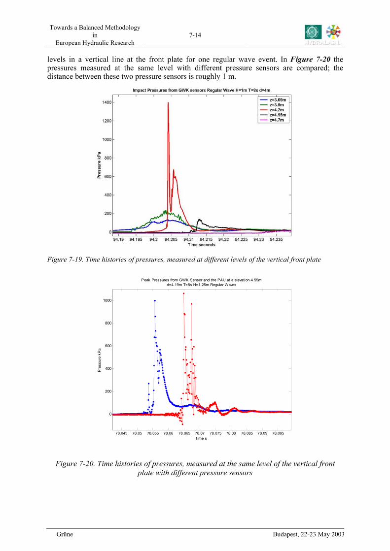
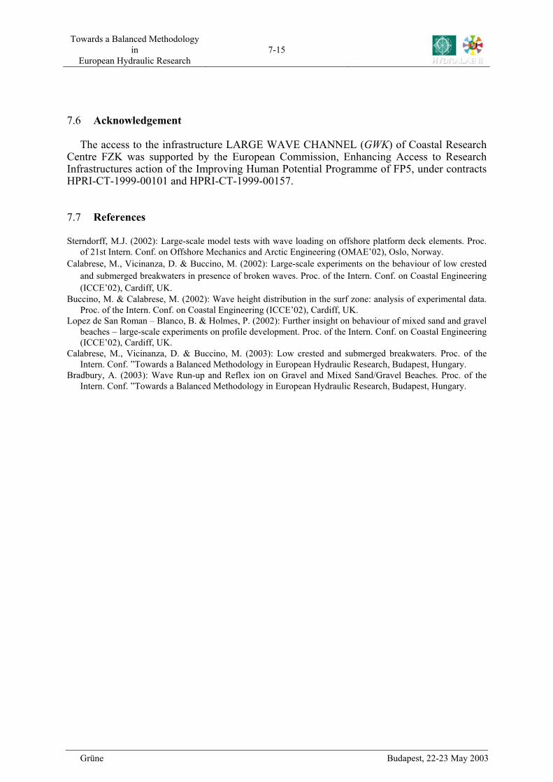
In Figure 7-19 and time histories of the pressures recorded at the vertical
front plate are shown exemplarily. gives the pressures measured at different Figure 7-20
Figure 7-19
Grüne Budapest, 22-23 May 2003
Towards a Balanced Methodology in
European Hydraulic Research 7-14
levels in a vertical line at the front plate for one regular wave event. In the pressures measured at the same level with different pressure sensors are compared; the distance between these two pressure sensors is roughly 1 m.
Figure 7-20
Figure 7-20. Time histories of pressures, measured at the same level of the vertical front plate with different pressure sensors
Figure 7-19. Time histories of pressures, measured at different levels of the vertical front plate
78.045 78.05 78.055 78.06 78.065 78.07 78.075 78.08 78.085 78.09 78.095
0
200
400
600
800
1000
Time s
Pre
ssur
e kP
a
Peak Pressures from GWK Sensor and the PAU at a elevation 4.55md=4.19m T=8s H=1.25m Regular Waves
Grüne Budapest, 22-23 May 2003
Towards a Balanced Methodology in
European Hydraulic Research 7-15
Grüne Budapest, 22-23 May 2003
7.6 Acknowledgement
The access to the infrastructure LARGE WAVE CHANNEL (GWK) of Coastal Research Centre FZK was supported by the European Commission, Enhancing Access to Research Infrastructures action of the Improving Human Potential Programme of FP5, under contracts HPRI-CT-1999-00101 and HPRI-CT-1999-00157.
7.7 References
Sterndorff, M.J. (2002): Large-scale model tests with wave loading on offshore platform deck elements. Proc. of 21st Intern. Conf. on Offshore Mechanics and Arctic Engineering (OMAE’02), Oslo, Norway.
Calabrese, M., Vicinanza, D. & Buccino, M. (2002): Large-scale experiments on the behaviour of low crested and submerged breakwaters in presence of broken waves. Proc. of the Intern. Conf. on Coastal Engineering (ICCE’02), Cardiff, UK.
Buccino, M. & Calabrese, M. (2002): Wave height distribution in the surf zone: analysis of experimental data. Proc. of the Intern. Conf. on Coastal Engineering (ICCE’02), Cardiff, UK.
Lopez de San Roman – Blanco, B. & Holmes, P. (2002): Further insight on behaviour of mixed sand and gravel beaches – large-scale experiments on profile development. Proc. of the Intern. Conf. on Coastal Engineering (ICCE’02), Cardiff, UK.
Calabrese, M., Vicinanza, D. & Buccino, M. (2003): Low crested and submerged breakwaters. Proc. of the Intern. Conf. ”Towards a Balanced Methodology in European Hydraulic Research, Budapest, Hungary.
Bradbury, A. (2003): Wave Run-up and Reflex ion on Gravel and Mixed Sand/Gravel Beaches. Proc. of the Intern. Conf. ”Towards a Balanced Methodology in European Hydraulic Research, Budapest, Hungary.


![Determination of optimal location for installation of symmetry … · established GOST 32144 – 2013 values [3]. Following performed investigations, there is sufficiently high level](https://img.pdfslide.net/doc/110x75/5f89ce1ff104fd3c1c2b9c6a/determination-of-optimal-location-for-installation-of-symmetry-established-gost.jpg)

![BiomedicalImageClassificationinaBigDataArchitectureUsing ...image databases into image categories before diagnostics [24–30]. Many investigations have been performed by re-searchers](https://img.pdfslide.net/doc/110x75/6149dc3512c9616cbc690969/biomedicalimageclassificationinabigdataarchitectureusing-image-databases-into.jpg)


![Numerical Investigations on Fluid Flow through Metal Screens · NUMERICAL INVESTIGATIONS ON FLUID FLOW THROUGH METAL SCREENS 5 et al. [1] performed calculations on screens used in](https://img.pdfslide.net/doc/110x75/5e288afacf173c3dbe461046/numerical-investigations-on-fluid-flow-through-metal-screens-numerical-investigations.jpg)