Embed Size (px)
Citation preview
Large Signal Identification (LSI) S1 Specification to the KLIPPEL ANALYZER SYSTEM (Document Revision 1.6)
FEATURES
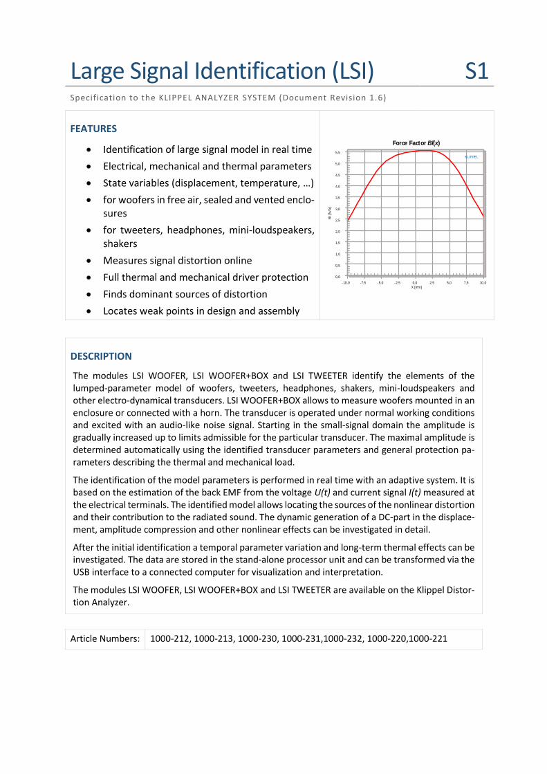
• Identification of large signal model in real time
• Electrical, mechanical and thermal parameters
• State variables (displacement, temperature, …)
• for woofers in free air, sealed and vented enclo-sures
• for tweeters, headphones, mini-loudspeakers, shakers
• Measures signal distortion online
• Full thermal and mechanical driver protection
• Finds dominant sources of distortion
• Locates weak points in design and assembly
KLIPPEL
0,0
0,5
1,0
1,5
2,0
2,5
3,0
3,5
4,0
4,5
5,0
5,5
-10,0 -7,5 -5,0 -2,5 0,0 2,5 5,0 7,5 10,0
Force Factor Bl(x)
Bl [
N/A
]
X [mm]
DESCRIPTION
The modules LSI WOOFER, LSI WOOFER+BOX and LSI TWEETER identify the elements of the lumped-parameter model of woofers, tweeters, headphones, shakers, mini-loudspeakers and other electro-dynamical transducers. LSI WOOFER+BOX allows to measure woofers mounted in an enclosure or connected with a horn. The transducer is operated under normal working conditions and excited with an audio-like noise signal. Starting in the small-signal domain the amplitude is gradually increased up to limits admissible for the particular transducer. The maximal amplitude is determined automatically using the identified transducer parameters and general protection pa-rameters describing the thermal and mechanical load.
The identification of the model parameters is performed in real time with an adaptive system. It is based on the estimation of the back EMF from the voltage U(t) and current signal I(t) measured at the electrical terminals. The identified model allows locating the sources of the nonlinear distortion and their contribution to the radiated sound. The dynamic generation of a DC-part in the displace-ment, amplitude compression and other nonlinear effects can be investigated in detail.
After the initial identification a temporal parameter variation and long-term thermal effects can be investigated. The data are stored in the stand-alone processor unit and can be transformed via the USB interface to a connected computer for visualization and interpretation.
The modules LSI WOOFER, LSI WOOFER+BOX and LSI TWEETER are available on the Klippel Distor-tion Analyzer.
Article Numbers: 1000-212, 1000-213, 1000-230, 1000-231,1000-232, 1000-220,1000-221
Large Signal Identification (LSI) 1 Large Signal Modeling of the Transducer S1
KLIPPEL Analyzer System Page 2 of 15
CONTENT
1 Large Signal Modeling of the Transducer ....................................................................................................... 3
2 Identification Technique ................................................................................................................................ 5
3 Limits .............................................................................................................................................................. 7
4 Measurement Results .................................................................................................................................... 9
5 Applications / Diagnostics ............................................................................................................................ 13
6 Patents ......................................................................................................................................................... 14
Large Signal Identification (LSI) 1 Large Signal Modeling of the Transducer S1
KLIPPEL Analyzer System Page 3 of 15
1 Large Signal Modeling of the Transducer
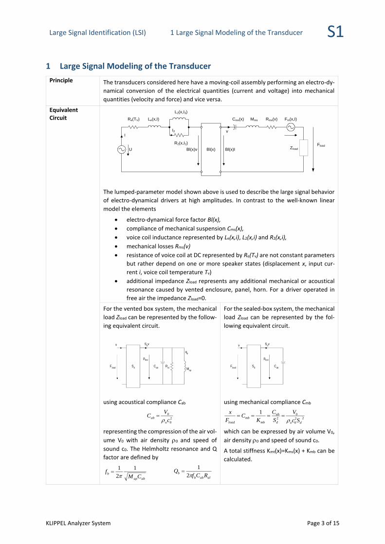
Principle The transducers considered here have a moving-coil assembly performing an electro-dy-
namical conversion of the electrical quantities (current and voltage) into mechanical
quantities (velocity and force) and vice versa.
Equivalent Circuit
MmsCms(x) Rms(v)
Bl(x)
Le(x,I)Re(TV)
v
Fm(x,I)
I
Bl(x)v Bl(x)I
L2(x,I3)
R2(x,I2)
U Zload
Fload
I2
The lumped-parameter model shown above is used to describe the large signal behavior
of electro-dynamical drivers at high amplitudes. In contrast to the well-known linear
model the elements
• electro-dynamical force factor Bl(x),
• compliance of mechanical suspension Cms(x),
• voice coil inductance represented by Le(x,i), L2(x,i) and R2(x,i),
• mechanical losses Rms(v)
• resistance of voice coil at DC represented by Re(Tv) are not constant parameters
but rather depend on one or more speaker states (displacement x, input cur-
rent i, voice coil temperature Tv)
• additional impedance Zload represents any additional mechanical or acoustical
resonance caused by vented enclosure, panel, horn. For a driver operated in
free air the impedance Zload=0.
For the vented box system, the mechanical
load Zload can be represented by the follow-
ing equivalent circuit.
Sd
Cab
pbox
Ral M
ap
Sdv
qp
Fload
v
using acoustical compliance Cab
2
0
0
c
VC
o
ab
=
representing the compression of the air vol-
ume V0 with air density 0 and speed of
sound c0. The Helmholtz resonance and Q
factor are defined by
abap
bCM
f1
2
1
=
alabb
bRCf
Q2
1=
For the sealed-box system, the mechanical
load Zload can be represented by the fol-
lowing equivalent circuit.
Sd
Cab
pbox
Sdv
Fload
v
using mechanical compliance Cmb
22
0
0
2
1
dod
ab
mb
mb
load Sc
V
S
C
KC
F
x
====
which can be expressed by air volume V0,
air density 0 and speed of sound c0.
A total stiffness Kmt(x)=Kms(x) + Kmb can be
calculated.

Large Signal Identification (LSI) 1 Large Signal Modeling of the Transducer S1
KLIPPEL Analyzer System Page 4 of 15
Thermal Model-ing
The heating of the voice coil is modeled by a thermal equivalent circuit comprising two
first order integrators connected in series describing the increase of the voice coil tem-
perature Tv and the increase of the magnet temperature Tm referred to the ambient
temperature Ta. The first integrator corresponds with the thermal resistance Rtv (heat
transfer between coil and pole tips) and the capacity Ctv (of the coil assembly). The sec-
ond integrator represents the thermal capacity Ctm (of the frame, magnet, iron path) and
the thermal resistance Rtm (heat transfer to the ambience).
The thermal resistance
vrms
tcrv
R1
=
represents air convection
cooling and depends on
the rms-value of the voice
coil velocity vrms and the
convection cooling pa-
rameter rV.
Rtv
Rtm
Ctv
Ctm
Tv T
m
Ta
Rtc(v)
Peg
Pcon
Ptv
Pmag
Pcoil
Tv T
m
The power 2
22
2
Re iRiRPPP eeddycoil +=+=
heats up the coil directly and consist of the power PRe dissipated in DC resistance Re and
a fraction of the power Peddy dissipated in R2 due to eddy currents weighted by power
splitting factor . The power 2
22)1()1( iRPP eddyeg −=−=
describes the remaining part of Peddy which is directly be transferred to the pole tips and
bypasses the coil.
Please find more information in the paper: W. Klippel, “Nonlinear Modeling of the Heat
Transfer in Loudspeakers,” J. Audio Eng. Soc. Vol. 52, No ½ 2004 January, February.
Operating Condi-tion
During the Large Signal Identification, the transducer has to be operated in free air (LSI
WOOFER, LSI TWEETER) or in a sealed or vented enclosure (LSI WOOFER+BOX). It is not
recommended to attach an additional mass to the moving assembly because this mass
might fall off at higher displacements.
Large Signal Identification (LSI) 2 Identification Technique S1
KLIPPEL Analyzer System Page 5 of 15
2 Identification Technique
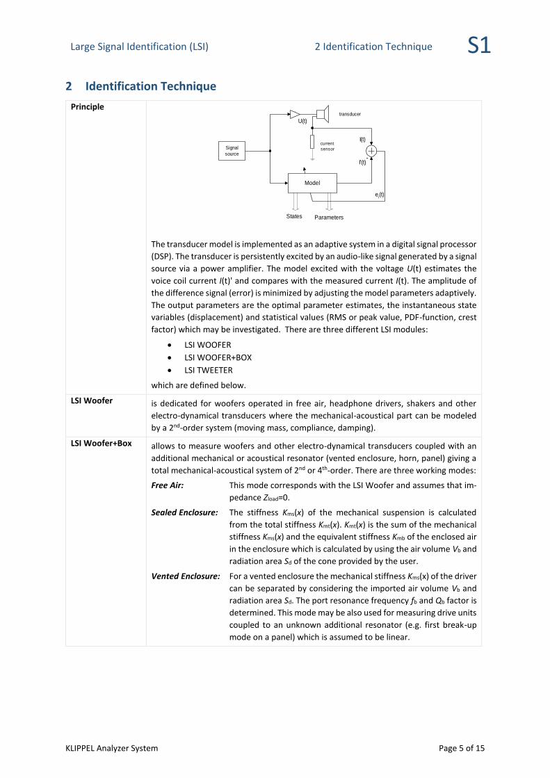
Principle
The transducer model is implemented as an adaptive system in a digital signal processor
(DSP). The transducer is persistently excited by an audio-like signal generated by a signal
source via a power amplifier. The model excited with the voltage U(t) estimates the
voice coil current I(t)' and compares with the measured current I(t). The amplitude of
the difference signal (error) is minimized by adjusting the model parameters adaptively.
The output parameters are the optimal parameter estimates, the instantaneous state
variables (displacement) and statistical values (RMS or peak value, PDF-function, crest
factor) which may be investigated. There are three different LSI modules:
• LSI WOOFER
• LSI WOOFER+BOX
• LSI TWEETER
which are defined below.
LSI Woofer is dedicated for woofers operated in free air, headphone drivers, shakers and other
electro-dynamical transducers where the mechanical-acoustical part can be modeled
by a 2nd-order system (moving mass, compliance, damping).
LSI Woofer+Box allows to measure woofers and other electro-dynamical transducers coupled with an
additional mechanical or acoustical resonator (vented enclosure, horn, panel) giving a
total mechanical-acoustical system of 2nd or 4th-order. There are three working modes:
Free Air: This mode corresponds with the LSI Woofer and assumes that im-
pedance Zload=0.
Sealed Enclosure: The stiffness Kms(x) of the mechanical suspension is calculated
from the total stiffness Kmt(x). Kmt(x) is the sum of the mechanical
stiffness Kms(x) and the equivalent stiffness Kmb of the enclosed air
in the enclosure which is calculated by using the air volume Vb and
radiation area Sd of the cone provided by the user.
Vented Enclosure: For a vented enclosure the mechanical stiffness Kms(x) of the driver
can be separated by considering the imported air volume Vb and
radiation area Sd. The port resonance frequency fb and Qb factor is
determined. This mode may be also used for measuring drive units
coupled to an unknown additional resonator (e.g. first break-up
mode on a panel) which is assumed to be linear.
Signal
source
Model
transducer
current
sensor
U(t)
I(t)
ei(t)
I'(t)-
States Parameters
Large Signal Identification (LSI) 2 Identification Technique S1
KLIPPEL Analyzer System Page 6 of 15
LSI Tweeter is dedicated for tweeters, horn compression drivers and micro-loudspeakers for tele-
communication which may be modeled by a 2nd-order mechanical system and a reso-
nance frequency above 400 Hz. It is recommended to perform the measurement in
vacuum to suppress nonlinearities of the air flow in small gaps and cavities.
Note: LSI TWEETER runs only with Klippel Distortion Analyzer 2 (DA2) and newer ver-
sions of DA 1 (serial number > 140), while LSI WOOFER and LSI WOOFER+BOX
work with all Distortion Analyzer hardware units.
Setup The minimal setup works without computer as a stand-alone system and dispenses with
an acoustical or mechanical sensor.
• Distortion Analyzer
• power amplifier
• amplifier and speaker cable
Usually a personal computer supports interpretation of the results. Optionally a laser
displacement sensor may be connected to check the polarity and the orientation of the
displacement (coil in and out direction).
Import Parameter
The minimal setup measures the electrical impedance at the transducer terminals and
identifies the electrical system in absolute quantities whereas the mechanical system is
identified in relative quantities only. Importing one mechanical parameter (moving
mass Mms or Bl(x=0) at the rest position) allows to calibrate all state variables (e.g. the
displacement in mm) and all of the mechanical parameters (e.g. compliance in mm/N).
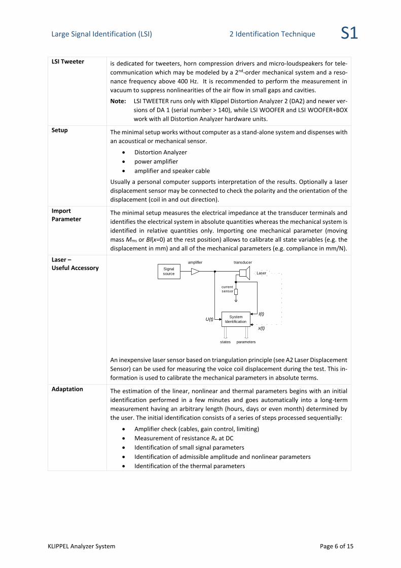
Laser – Useful Accessory
An inexpensive laser sensor based on triangulation principle (see A2 Laser Displacement
Sensor) can be used for measuring the voice coil displacement during the test. This in-
formation is used to calibrate the mechanical parameters in absolute terms.
Adaptation The estimation of the linear, nonlinear and thermal parameters begins with an initial
identification performed in a few minutes and goes automatically into a long-term
measurement having an arbitrary length (hours, days or even month) determined by
the user. The initial identification consists of a series of steps processed sequentially:
• Amplifier check (cables, gain control, limiting)
• Measurement of resistance Re at DC
• Identification of small signal parameters
• Identification of admissible amplitude and nonlinear parameters
• Identification of the thermal parameters
Signal
source
System
Identification
transducer
current
sensor
x(t)
Laser
I(t)U(t)
amplifier
states parameters
Large Signal Identification (LSI) 3 Limits S1
KLIPPEL Analyzer System Page 7 of 15
Protection Signal
Source
Model
transducer
current
sensor
U(t)
I(t)Gain
Adjustment
Protection
Setup
Gsmall
Glarge Power Amplifier
Protection
Variables
Protection
Limits
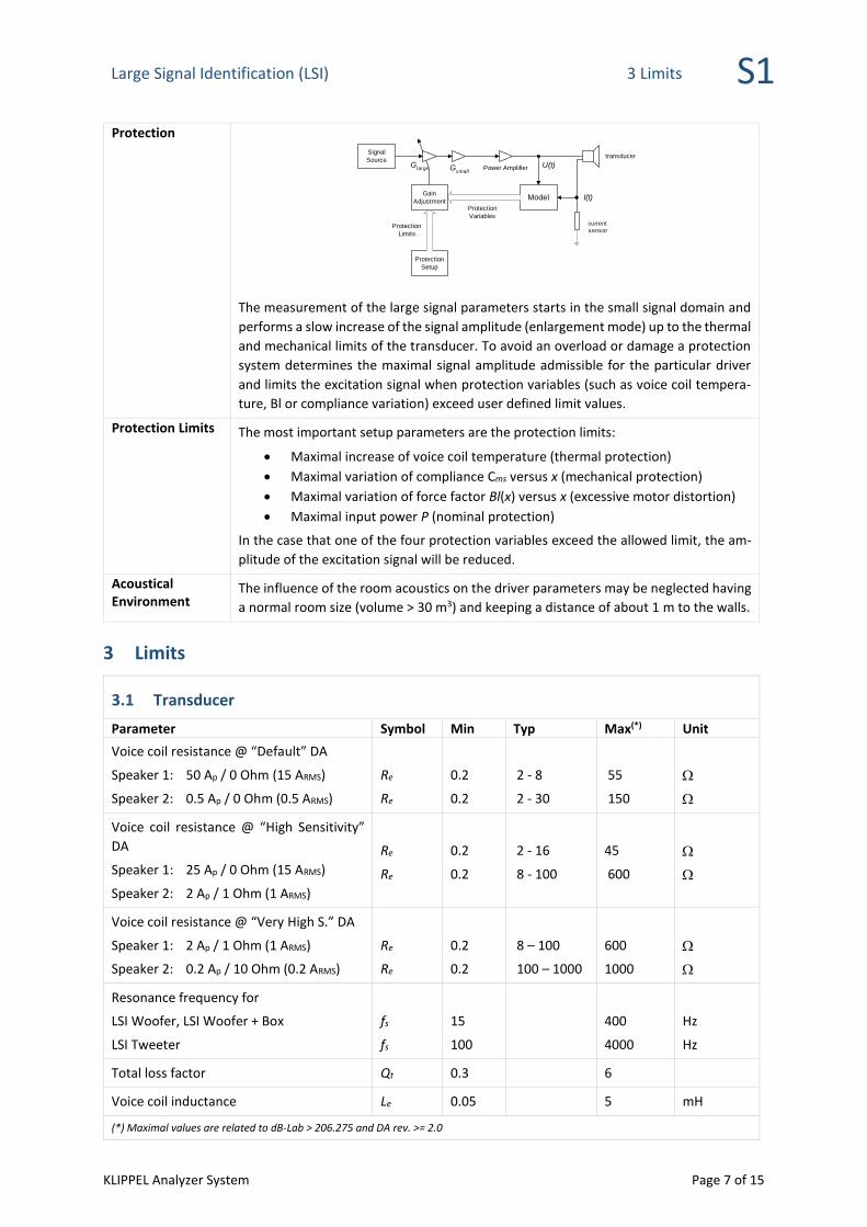
The measurement of the large signal parameters starts in the small signal domain and
performs a slow increase of the signal amplitude (enlargement mode) up to the thermal
and mechanical limits of the transducer. To avoid an overload or damage a protection
system determines the maximal signal amplitude admissible for the particular driver
and limits the excitation signal when protection variables (such as voice coil tempera-
ture, Bl or compliance variation) exceed user defined limit values.
Protection Limits The most important setup parameters are the protection limits:
• Maximal increase of voice coil temperature (thermal protection)
• Maximal variation of compliance Cms versus x (mechanical protection)
• Maximal variation of force factor Bl(x) versus x (excessive motor distortion)
• Maximal input power P (nominal protection)
In the case that one of the four protection variables exceed the allowed limit, the am-
plitude of the excitation signal will be reduced.
Acoustical Environment
The influence of the room acoustics on the driver parameters may be neglected having
a normal room size (volume > 30 m3) and keeping a distance of about 1 m to the walls.
3 Limits
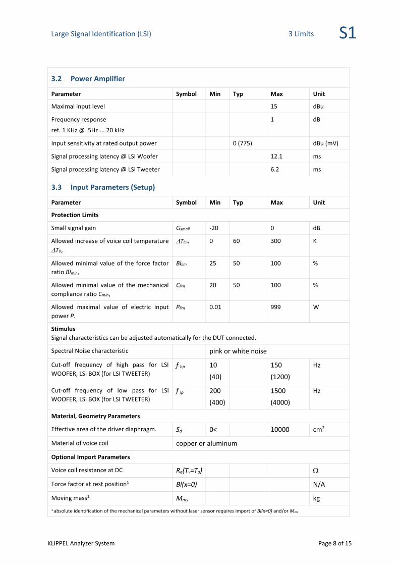
3.1 Transducer
Parameter Symbol Min Typ Max(*) Unit
Voice coil resistance @ “Default” DA
Speaker 1: 50 Ap / 0 Ohm (15 ARMS)
Speaker 2: 0.5 Ap / 0 Ohm (0.5 ARMS)
Re
Re
0.2
0.2
2 - 8
2 - 30
55
150
Voice coil resistance @ “High Sensitivity”
DA
Speaker 1: 25 Ap / 0 Ohm (15 ARMS)
Speaker 2: 2 Ap / 1 Ohm (1 ARMS)
Re
Re
0.2
0.2
2 - 16
8 - 100
45
600
Voice coil resistance @ “Very High S.” DA
Speaker 1: 2 Ap / 1 Ohm (1 ARMS)
Speaker 2: 0.2 Ap / 10 Ohm (0.2 ARMS)
Re
Re
0.2
0.2
8 – 100
100 – 1000
600
1000
Resonance frequency for
LSI Woofer, LSI Woofer + Box
LSI Tweeter
fs
fs
15
100
400
4000
Hz
Hz
Total loss factor Qt 0.3 6
Voice coil inductance Le 0.05 5 mH
(*) Maximal values are related to dB-Lab > 206.275 and DA rev. >= 2.0
Large Signal Identification (LSI) 3 Limits S1
KLIPPEL Analyzer System Page 8 of 15
3.2 Power Amplifier
Parameter Symbol Min Typ Max Unit
Maximal input level 15 dBu
Frequency response
ref. 1 KHz @ 5Hz ... 20 kHz
1 dB
Input sensitivity at rated output power 0 (775) dBu (mV)
Signal processing latency @ LSI Woofer 12.1 ms
Signal processing latency @ LSI Tweeter 6.2 ms
3.3 Input Parameters (Setup)
Parameter Symbol Min Typ Max Unit
Protection Limits
Small signal gain Gsmall -20 0 dB
Allowed increase of voice coil temperature
TV,
Tlim 0 60 300 K
Allowed minimal value of the force factor
ratio Blmin,
Bllim 25 50 100 %
Allowed minimal value of the mechanical
compliance ratio Cmin,
Clim 20 50 100 %
Allowed maximal value of electric input
power P.
Plim 0.01 999 W
Stimulus
Signal characteristics can be adjusted automatically for the DUT connected.
Spectral Noise characteristic pink or white noise
Cut-off frequency of high pass for LSI
WOOFER, LSI BOX (for LSI TWEETER) f hp 10
(40)
150
(1200)
Hz
Cut-off frequency of low pass for LSI
WOOFER, LSI BOX (for LSI TWEETER) f lp 200
(400)
1500
(4000)
Hz
Material, Geometry Parameters
Effective area of the driver diaphragm. Sd 0< 10000 cm2
Material of voice coil copper or aluminum
Optional Import Parameters
Voice coil resistance at DC Re(Tv=Ta)
Force factor at rest position1 Bl(x=0) N/A
Moving mass1 Mms kg
1 absolute identification of the mechanical parameters without laser sensor requires import of Bl(x=0) and/or Mms
Large Signal Identification (LSI) 4 Results S1
KLIPPEL Analyzer System Page 9 of 15
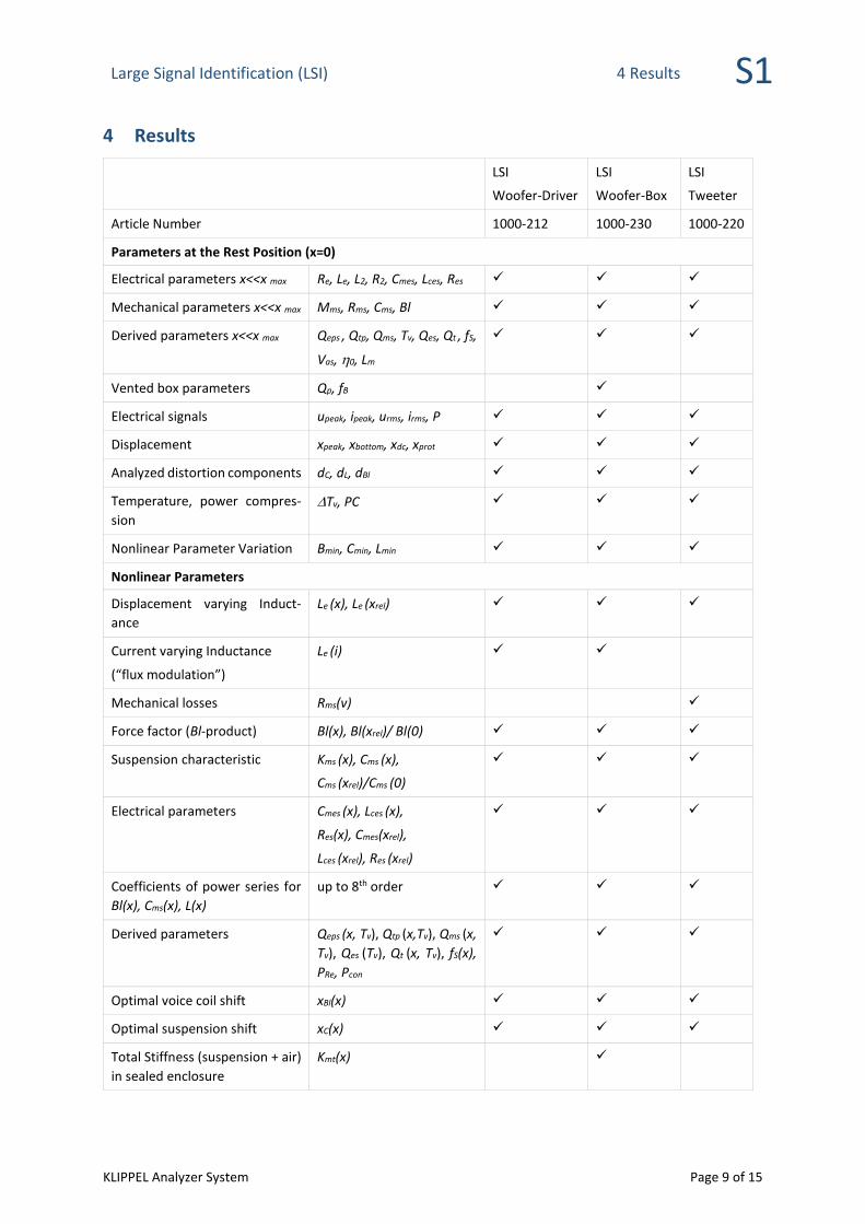
4 Results
LSI
Woofer-Driver
LSI
Woofer-Box
LSI
Tweeter
Article Number 1000-212 1000-230 1000-220
Parameters at the Rest Position (x=0)
Electrical parameters x<<x max Re, Le, L2, R2, Cmes, Lces, Res ✓ ✓ ✓
Mechanical parameters x<<x max Mms, Rms, Cms, Bl ✓ ✓ ✓
Derived parameters x<<x max Qeps , Qtp, Qms, Tv, Qes, Qt , fS,
Vas, 0, Lm
✓ ✓ ✓
Vented box parameters Qp, fB ✓
Electrical signals upeak, ipeak, urms, irms, P ✓ ✓ ✓
Displacement xpeak, xbottom, xdc, xprot ✓ ✓ ✓
Analyzed distortion components dC, dL, dBl ✓ ✓ ✓
Temperature, power compres-
sion
Tv, PC ✓ ✓ ✓
Nonlinear Parameter Variation Bmin, Cmin, Lmin ✓ ✓ ✓
Nonlinear Parameters
Displacement varying Induct-
ance
Le (x), Le (xrel) ✓ ✓ ✓
Current varying Inductance
(“flux modulation”)
Le (i) ✓ ✓
Mechanical losses Rms(v) ✓
Force factor (Bl-product) Bl(x), Bl(xrel)/ Bl(0) ✓ ✓ ✓
Suspension characteristic Kms (x), Cms (x),
Cms (xrel)/Cms (0)
✓ ✓ ✓
Electrical parameters Cmes (x), Lces (x),
Res(x), Cmes(xrel),
Lces (xrel), Res (xrel)
✓ ✓ ✓
Coefficients of power series for
Bl(x), Cms(x), L(x)
up to 8th order ✓ ✓ ✓
Derived parameters Qeps (x, Tv), Qtp (x,Tv), Qms (x,
Tv), Qes (Tv), Qt (x, Tv), fS(x),
PRe, Pcon
✓ ✓ ✓
Optimal voice coil shift xBl(x) ✓ ✓ ✓
Optimal suspension shift xC(x) ✓ ✓ ✓
Total Stiffness (suspension + air)
in sealed enclosure
Kmt(x) ✓
Large Signal Identification (LSI) 4 Results S1
KLIPPEL Analyzer System Page 10 of 15
Thermal Parameters
Thermal resistance Rtv, Rtm, rV ✓ ✓ ✓
Thermal capacity Ctv, Ctm, τtm, τtv ✓ ✓ ✓
Convection Cooling rv, ✓ ✓ ✓
Heating by eddy currents α ✓ ✓ ✓
History
Parameter and state variation versus measurement time t ✓ ✓ ✓
Background monitoring at high sample rate (Death Report) ✓ ✓ ✓
Export
Result windows to report generator ✓ ✓ ✓
Graphics to Clipboard, File (various formats) ✓ ✓ ✓
Parameters for Auralization ✓ ✓ ✓
Parameters for Simulation ✓ ✓ ✓
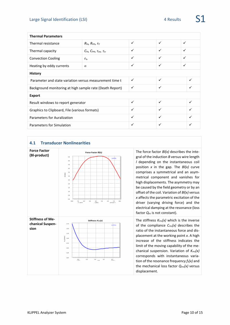
4.1 Transducer Nonlinearities
Force Factor (Bl-product)
The force factor Bl(x) describes the inte-
gral of the induction B versus wire length
l depending on the instantaneous coil
position x in the gap. The Bl(x) curve
comprises a symmetrical and an asym-
metrical component and vanishes for
high displacements. The asymmetry may
be caused by the field geometry or by an
offset of the coil. Variation of Bl(x) versus
x affects the parametric excitation of the
driver (varying driving force) and the
electrical damping at the resonance (loss
factor Qes is not constant).
Stiffness of Me-chanical Suspen-sion
The stiffness Kms(x) which is the inverse
of the compliance Cms(x) describes the
ratio of the instantaneous force and dis-
placement at the working point x. A high
increase of the stiffness indicates the
limit of the moving capability of the me-
chanical suspension. Variation of Kms(x)
corresponds with instantaneous varia-
tion of the resonance frequency fS(x) and
the mechanical loss factor Qms(x) versus
displacement.
KLIPPEL
0,0 0,5 1,0 1,5 2,0 2,5 3,0 3,5 4,0 4,5 5,0 5,5
-10,0 -7,5 -5,0 -2,5 0,0 2,5 5,0 7,5 10,0
Force Factor Bl(x)
Bl [N
/A]
<< coil in x [mm] coil out >>
KLIPPEL
0,00
0,25
0,50
0,75
1,00
1,25
1,50
1,75
-5,0 -2,5 0,0 2,5 5,0
Stiffness KMS(x)
KM
S [N
/mm
]
<< coil in x [mm] coil out >>
Large Signal Identification (LSI) 4 Results S1
KLIPPEL Analyzer System Page 11 of 15
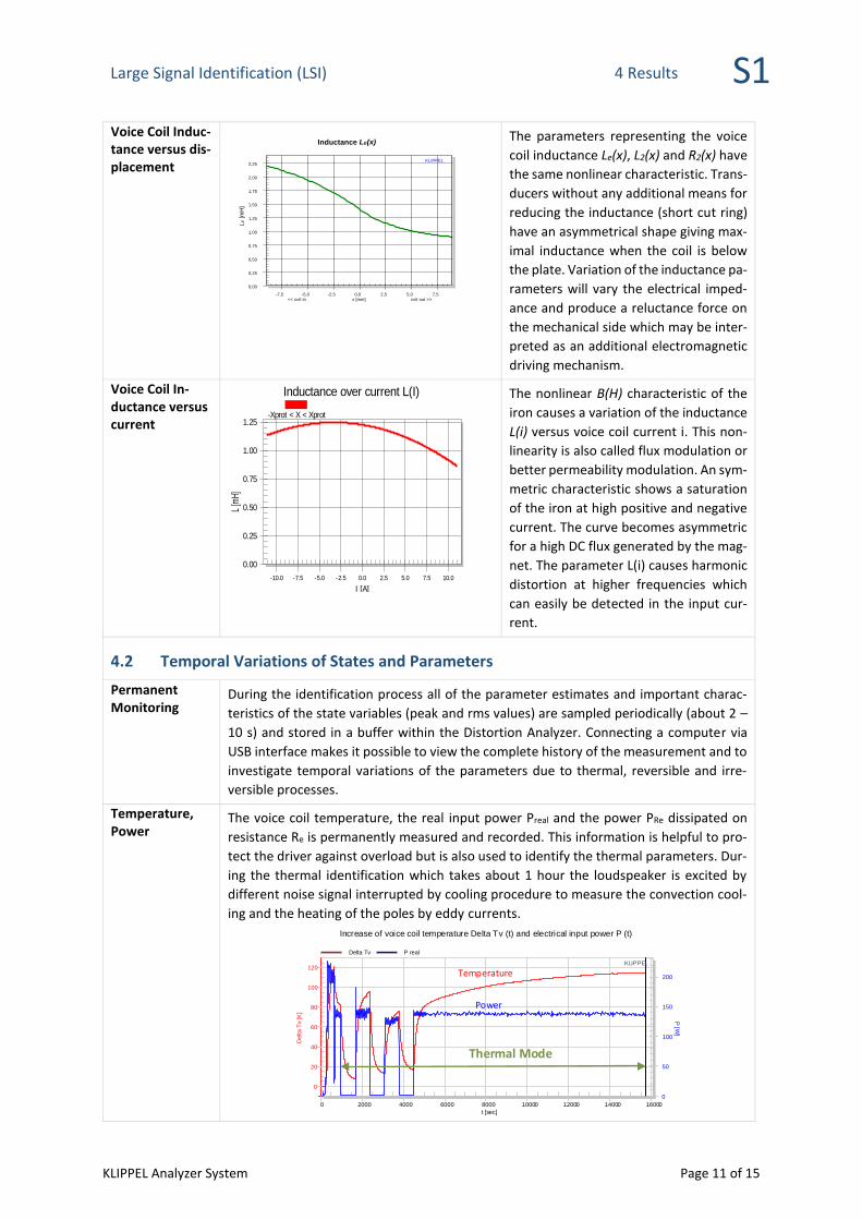
Voice Coil Induc-tance versus dis-placement
The parameters representing the voice
coil inductance Le(x), L2(x) and R2(x) have
the same nonlinear characteristic. Trans-
ducers without any additional means for
reducing the inductance (short cut ring)
have an asymmetrical shape giving max-
imal inductance when the coil is below
the plate. Variation of the inductance pa-
rameters will vary the electrical imped-
ance and produce a reluctance force on
the mechanical side which may be inter-
preted as an additional electromagnetic
driving mechanism.
Voice Coil In-ductance versus current
The nonlinear B(H) characteristic of the
iron causes a variation of the inductance
L(i) versus voice coil current i. This non-
linearity is also called flux modulation or
better permeability modulation. An sym-
metric characteristic shows a saturation
of the iron at high positive and negative
current. The curve becomes asymmetric
for a high DC flux generated by the mag-
net. The parameter L(i) causes harmonic
distortion at higher frequencies which
can easily be detected in the input cur-
rent.
4.2 Temporal Variations of States and Parameters
Permanent Monitoring
During the identification process all of the parameter estimates and important charac-
teristics of the state variables (peak and rms values) are sampled periodically (about 2 –
10 s) and stored in a buffer within the Distortion Analyzer. Connecting a computer via
USB interface makes it possible to view the complete history of the measurement and to
investigate temporal variations of the parameters due to thermal, reversible and irre-
versible processes.
Temperature, Power
The voice coil temperature, the real input power Preal and the power PRe dissipated on
resistance Re is permanently measured and recorded. This information is helpful to pro-
tect the driver against overload but is also used to identify the thermal parameters. Dur-
ing the thermal identification which takes about 1 hour the loudspeaker is excited by
different noise signal interrupted by cooling procedure to measure the convection cool-
ing and the heating of the poles by eddy currents.
KLIPPEL
0
20
40
60
80
100
120
0
50
100
150
200
0 2000 4000 6000 8000 10000 12000 14000 16000
Increase of voice coil temperature Delta Tv (t) and electrical input power P (t)
Delta
Tv
[K]
P [W
]
t [sec]
Delta Tv P real
Temperature
Power
Thermal Mode
0.00
0.25
0.50
0.75
1.00
1.25
-10.0 -7.5 -5.0 -2.5 0.0 2.5 5.0 7.5 10.0
Inductance over current L(I)
L [m
H]
I [A]
-Xprot < X < Xprot
KLIPPEL
0,00 0,25 0,50 0,75 1,00 1,25 1,50 1,75 2,00 2,25
-7,5 -5,0 -2,5 0,0 2,5 5,0 7,5
Inductance LE(x)
LE [m
H]
<< coil in x [mm] coil out >>
Large Signal Identification (LSI) 4 Results S1
KLIPPEL Analyzer System Page 12 of 15
Stiffness of Me-chanical Suspen-sion KLIPPEL
0,0
0,2
0,4
0,6
0,8
1,0
1,2
46
48
50
52
54
56
0 100 200 300 400 500 600 700 800 900 1000
Stiffness Kms (t) and resonance frequency fs (t) at rest position X=000:16:40
Km
s [N
/mm
]
fs [H
z]
t [sec]
Kms (X=0) fs (X=0)
fs(t)Kms(t)
The properties of the me-
chanical suspension vary
with time due to reversi-
ble and nonreversible
processes (creep, ageing).
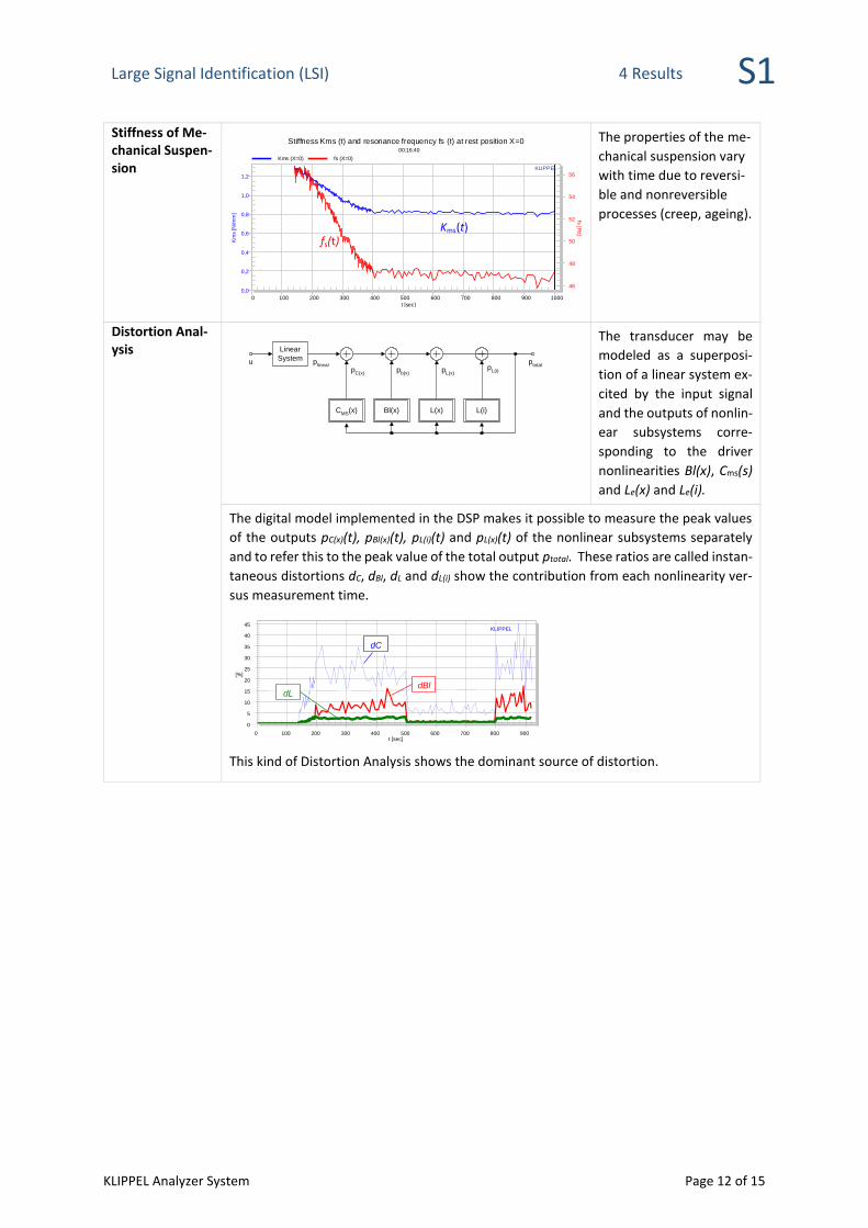
Distortion Anal-ysis
Linear
System
CMS
(x) Bl(x) L(x)
ptotal
u plinear
pC(x)
pb(x)
pL(x)
L(i)
pL(i)
The transducer may be
modeled as a superposi-
tion of a linear system ex-
cited by the input signal
and the outputs of nonlin-
ear subsystems corre-
sponding to the driver
nonlinearities Bl(x), Cms(s)
and Le(x) and Le(i).
The digital model implemented in the DSP makes it possible to measure the peak values
of the outputs pC(x)(t), pBl(x)(t), pL(i)(t) and pL(x)(t) of the nonlinear subsystems separately
and to refer this to the peak value of the total output ptotal. These ratios are called instan-
taneous distortions dC, dBl, dL and dL(i) show the contribution from each nonlinearity ver-
sus measurement time.
KLIPPEL
0
5
10
15
20
25
30
35
40
45
0 100 200 300 400 500 600 700 800 900
[%]
t [sec]
dBl dL
dC
This kind of Distortion Analysis shows the dominant source of distortion.
Large Signal Identification (LSI) 5 Applications / Diagnostics S1
KLIPPEL Analyzer System Page 13 of 15
5 Applications / Diagnostics
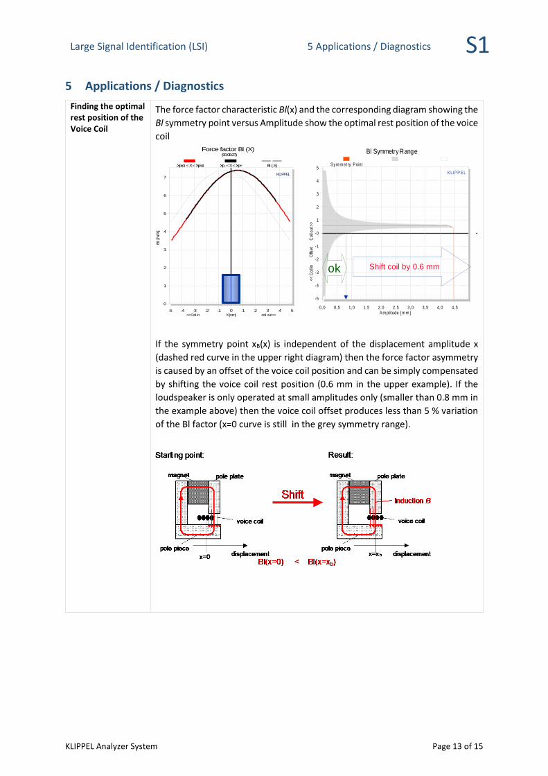
Finding the optimal rest position of the Voice Coil
The force factor characteristic Bl(x) and the corresponding diagram showing the
Bl symmetry point versus Amplitude show the optimal rest position of the voice
coil
If the symmetry point xB(x) is independent of the displacement amplitude x
(dashed red curve in the upper right diagram) then the force factor asymmetry
is caused by an offset of the voice coil position and can be simply compensated
by shifting the voice coil rest position (0.6 mm in the upper example). If the
loudspeaker is only operated at small amplitudes only (smaller than 0.8 mm in
the example above) then the voice coil offset produces less than 5 % variation
of the Bl factor (x=0 curve is still in the grey symmetry range).
KLIPPEL
0
1
2
3
4
5
6
7
-5 -4 -3 -2 -1 0 1 2 3 4 5
Force factor Bl (X) (00:08:27)
Bl [N
/A]
<< Coil in X [mm] coil out >>
-Xprot < X < Xprot Xp- < X < Xp+ Bl (-X)
KLIPPEL
Bl Symmetry Range
<<
Co
il in
O
ffse
t
C
oil
ou
t >>
Am plitude [m m ]
-5
-4
-3
-2
-1
-0
1
2
3
4
5
0,0 0,5 1,0 1,5 2,0 2,5 3,0 3,5 4,0 4,5
Sym m etry Point
Shift coil by 0.6 mmok
KLIPPEL
Bl Symmetry Range
<<
Co
il in
O
ffse
t
C
oil
ou
t >>
Am plitude [m m ]
-5
-4
-3
-2
-1
-0
1
2
3
4
5
0,0 0,5 1,0 1,5 2,0 2,5 3,0 3,5 4,0 4,5
Sym m etry Point
Shift coil by 0.6 mmok
Large Signal Identification (LSI) 6 Patents S1
KLIPPEL Analyzer System Page 14 of 15
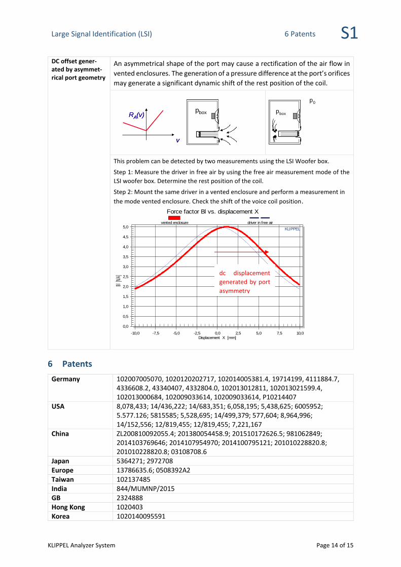
DC offset gener-ated by asymmet-rical port geometry
An asymmetrical shape of the port may cause a rectification of the air flow in
vented enclosures. The generation of a pressure difference at the port’s orifices
may generate a significant dynamic shift of the rest position of the coil.
v
R A (v)
v
R A (v) p box
p 0
p box
This problem can be detected by two measurements using the LSI Woofer box.
Step 1: Measure the driver in free air by using the free air measurement mode of the
LSI woofer box. Determine the rest position of the coil.
Step 2: Mount the same driver in a vented enclosure and perform a measurement in
the mode vented enclosure. Check the shift of the voice coil position.
6 Patents
Germany 102007005070, 1020120202717, 102014005381.4, 19714199, 4111884.7, 4336608.2, 43340407, 4332804.0, 102013012811, 102013021599.4, 102013000684, 102009033614, 102009033614, P10214407
USA 8,078,433; 14/436,222; 14/683,351; 6,058,195; 5,438,625; 6005952; 5.577.126; 5815585; 5,528,695; 14/499,379; 577,604; 8,964,996; 14/152,556; 12/819,455; 12/819,455; 7,221,167
China ZL200810092055.4; 201380054458.9; 201510172626.5; 981062849; 2014103769646; 2014107954970; 2014100795121; 201010228820.8; 201010228820.8; 03108708.6
Japan 5364271; 2972708 Europe 13786635.6; 0508392A2 Taiwan 102137485 India 844/MUMNP/2015 GB 2324888 Hong Kong 1020403 Korea 1020140095591
KLIPPEL
0,0
0,5
1,0
1,5
2,0
2,5
3,0
3,5
4,0
4,5
5,0
-10,0 -7,5 -5,0 -2,5 0,0 2,5 5,0 7,5 10,0
Force factor Bl vs. displacement X
Bl [N
/A]
Displacement X [mm]
vented enclosure driver in free air
dc displacement
generated by port
asymmetry
Large Signal Identification (LSI) 6 Patents S1
KLIPPEL Analyzer System Page 15 of 15
Find explanations for symbols at:
http://www.klippel.de/know-how/literature.html
Last updated: October 07, 2019
Designs and specifications are subject to change without no-
tice due to modifications or improvements.