Embed Size (px)
Citation preview

SDHT/SDHT 2000 User Manual Page 1 of 71 060-1000-0034-00J
Larson Systems Inc. Phone: 763-780-2131 10073 Baltimore Street N.E. Toll Free: 1-877-780-2131 Minneapolis, MN 55449-4425 Fax: 763-780-2182 www.larsonsystems.com E-mail: [email protected]
Larson Systems Inc.
Super Digital Hand Tester/ Super Digital Hand Tester 2000/
SDHT 2000 Wide Body User Manual
Current for Software Version 4.25

SDHT/SDHT 2000 User Manual Page 2 of 71 060-1000-0034-00J
About This Manual This manual could contain technical inaccuracies or typographical errors. Changes are periodically made to the information contained herein. These changes will be incorporated in new editions of the manual.
Copyright © 2011 Larson Systems Inc.
All rights reserved. No part of this manual may be reproduced by any means without written permission of the author, except portions necessary for internal use only by the purchaser of the LSI system.

SDHT/SDHT 2000 User Manual Page 3 of 71 060-1000-0034-00J
1 INTRODUCTION.....................................................................................................................6
1.1 SDHT Features .......................................................................................................................................................... 6
1.2 SDHT 2000 Features ................................................................................................................................................ 6
1.3 SDHT 2000 Wide Body Features............................................................................................................................ 7
1.4 Additional Options ................................................................................................................................................... 7 1.4.1 Safety and Usage Considerations ..................................................................................................................... 7
1.5 Tester Specifications ............................................................................................................................................... 8 Force Specifications..................................................................................................................................................... 8 SDHT-Force Specifications ......................................................................................................................................... 8 Length Specifications................................................................................................................................................. 10
Part Capacity ................................................................................................................................................................. 11
Physical Dimensions ................................................................................................................................................... 12
2.0 FIRST STEPS ....................................................................................................................14
2.1 Unpacking your SDHT or SDHT 2000 ................................................................................................................. 14
2.1 Tester Setup ............................................................................................................................................................ 15
2.2 Handle Setup......................................................................................................................................................... 15
2.3 Power Supply/Battery Charger ............................................................................................................................ 15
2.4 RS 232 Communications Port .............................................................................................................................. 16
2.5 Stroke Lock—SDHT 2000...................................................................................................................................... 17
2.6 Range Adjustment Locks...................................................................................................................................... 17
2.7 SDHT Overload Screws......................................................................................................................................... 17
2.7 Micro Length Adjust with Built-in Stops ............................................................................................................ 18 2.7.1 Micro Length Adjust—SDHT............................................................................................................................ 18 2.7.2 Micro Length Adjust—SDHT 2000 .................................................................................................................. 18
2.8 Built-in Length Stops............................................................................................................................................. 19
2.9 Air Vibration Damping Table ................................................................................................................................ 19 Air Vibration Damping Table Setup........................................................................................................................... 20
3.0 FEATURES AND CONTROLS ..........................................................................................21
3.1 Buttons..................................................................................................................................................................... 21
3.2 Turning on the SDHT ............................................................................................................................................. 22
3.3 Turning off the SDHT ............................................................................................................................................. 22

SDHT/SDHT 2000 User Manual Page 4 of 71 060-1000-0034-00J
3.4 Backlight Off and Power Off Timers ................................................................................................................... 22
3.5 Selecting Measurement Units .............................................................................................................................. 23
3.6 Storing Test Data.................................................................................................................................................... 23
3.7 Force and Length Initialization ............................................................................................................................ 24 3.7.1 Compression Force Initialization ..................................................................................................................... 24 3.7.2 Compression Length Initialization .................................................................................................................. 24 3.7.3 Extension Force Initialization ........................................................................................................................... 25 3.7.5 Length Initialization with Setup Blocks ............................................................................................................ 26
Extension Blocks.......................................................................................................................................................... 26
3.8 Test Modes .............................................................................................................................................................. 27
3.9 Sending Data........................................................................................................................................................... 28 3.9.1 Printout Examples............................................................................................................................................. 29 3.9.2 Sending Current Data....................................................................................................................................... 30 3.9.3 Sending Stored Test Data................................................................................................................................ 30 3.9.4 Retrieving Test Data via Computer ................................................................................................................. 31 3.9.5 Viewing Test Data on a Computer................................................................................................................... 31 3.9.6 Description of data format output ................................................................................................................... 32
4.0 OPERATION ......................................................................................................................33
4.1 Measuring a Compression Spring....................................................................................................................... 33
4.2 Measuring an Extension Spring .......................................................................................................................... 34
4.3 Measuring Peak Force........................................................................................................................................... 36
4.4 Measuring Spring Rate.......................................................................................................................................... 38 4.4.1 Spring Rate - Print or Store Data Directly ....................................................................................................... 38 4.4.2 Spring Rate - Display Data............................................................................................................................... 39
5.0 OPTION MENU ..................................................................................................................40
5.1 Store ......................................................................................................................................................................... 41
5.2 EndPrint ................................................................................................................................................................... 42
5.3 Limit Options........................................................................................................................................................... 43
5.4 Offset ........................................................................................................................................................................ 44
5.6 Calibration Check................................................................................................................................................... 45
5.7 User Setup ............................................................................................................................................................... 46 5.7.1 User Setup—Getting Ready to Print a Report from the RS 232 ................................................................... 47 5.7.2 User Setup—Getting Ready to Transmit Data via the RS 232 ..................................................................... 49 5.7.3 User Setup—Power Timeout ........................................................................................................................... 51 5.7.4 User Setup—Dampening ................................................................................................................................. 52 5.7.5 User Setup—Date and Time............................................................................................................................ 52 5.7.6 User Setup—Company Name ......................................................................................................................... 53 5.7.6 User Setup—City Name................................................................................................................................... 54 5.7.8 User Setup—Backlight Timeout....................................................................................................................... 55 5.7.9 User Setup—Units Used .................................................................................................................................. 55 5.7.10—User Setup—First Peak Drop ..................................................................................................................... 56
SDHT/SDHT 2000 User Manual Page 5 of 71 060-1000-0034-00J
5.7.11 User Setup—Filtering ..................................................................................................................................... 57 5.7.13 User Setup—Plus or Minus +/- Force Rule .................................................................................................. 58
5.8 Diagnostics.............................................................................................................................................................. 59 5.8.1 Diagnostics—Battery Voltage .......................................................................................................................... 60 5.8.2 Diagnostics—Keypad Check ........................................................................................................................... 60 5.8.3 Diagnostics—Screen Check ............................................................................................................................ 61 5.8.4 Diagnostics—Output Diagnostics Test............................................................................................................ 62 5.8.5 Diagnostics—RS 232 Protocols....................................................................................................................... 62 5.8.6 Diagnostics—RS 232 Output Format .............................................................................................................. 63 5.8.7 Diagnostics—RS 232 Check............................................................................................................................ 63 5.8.8 Diagnostics—Processor Check ....................................................................................................................... 64 5.8.9 Diagnostics—Smart Memory (SM)................................................................................................................. 64 5.8.10 Diagnostics—Print Cell Info ........................................................................................................................... 64 5.8.11 Diagnostics—Print All Info ............................................................................................................................. 65
5.9 Calibration Menus .................................................................................................................................................. 65
5.10 Factory Setup........................................................................................................................................................ 65
6.0 SDHT ERROR MESSAGES...............................................................................................66
7.0 TESTER DEFAULTS .........................................................................................................69
8.0 TESTER MAINTENANCE..................................................................................................69
Title.................................................................................................................................................................................. 70
Warranty ......................................................................................................................................................................... 70

SDHT/SDHT 2000 User Manual Page 6 of 71 060-1000-0034-00J
1 INTRODUCTION The Super Digital Hand Tester comes in three distinct models: SDHT, SDHT 2000 and SDHT 2000 Wide Body. All models are manually-operated force and length testers designed for in-process control measurements right on the factory floor. Bright, two-line backlit LCD displays allow easy viewing of highly accurate length and force measurements. Both testers can select a variety of measurement units, both English and Metric, for ease of use. Length measurement can be selected to read in inches or millimeters; force measurement can be selected to read in ounces, pounds, Newtons, grams or kilograms. Both models operate in compression or extension mode and feature a high degree of built-in precision and accuracy to assure excellent repeatability and reproducibility.
1.1 SDHT Features Compression and extension testing of force and length Tracking or peak modes (2,000 samples / sec) Load cell and frame deflection compensation Mechanical and software overload protection Built-in shunt calibration verification Backlit digital LCD display of force and length Wipe-clean embossed key faceplate Push button force and length zeroing Push button English or metric unit selection User programmable filter Length / force offset Customizable print headings Front panel digital calibration NIST traceable calibration Micro-Length Adjust with built-in length stops Internal 8 hour battery for portable use RS 232 data communications port Statistical summary printout Built-in 1,800 test point data logger Complete computerized tester diagnostics High resolution linear scale
1.2 SDHT 2000 Features All Standard SDHT Features, plus... Smart, interchangeable load cell capability Lever operation or choice of high or low fine-adjust wheel 2,000 lb capacity Increased range, stroke and platform diameter Rigid two-column design

SDHT/SDHT 2000 User Manual Page 7 of 71 060-1000-0034-00J
1.3 SDHT 2000 Wide Body Features All SDHT 2000 features, plus... Super-rigid four-post frame 16”-diameter platform
1.4 Additional Options Thru-rod support kit 4” extended platforms for SDHT 8” extended platforms for SDHT 2000, 16” for SDHT Wide Body Vibration damping options Wire crimp attachments Wedge grip attachments Dust covers Extension hooks for all applications Twist Under Load (TUL) indicating attachment Squareness Under Load (SUL) indicating attachment Digital Squareness Under Load (DSUL) indicating attachment Statistical and Spreadsheet Interface Software (SSS) for PC communication Printer for statistical printouts
1.4.1 Safety and Usage Considerations Before you use your SDHT, read this manual to gain an understanding of its proper operation. Observe the following important considerations: Compressed or extended springs have stored potential energy proportional to the spring constant. Use care and release this energy in a controlled manner to avoid possible injury.
Do not apply more force than the tester is designed to handle. The tester has overload stops to protect it, but damage can still result from excessive loads. Force readings are not accurate above the rated limit.
Be sure the operating location is clean and dry, and all parts to be tested are free of oil and contaminants.
Keep your SDHT away from any source of liquid. Keep this user manual handy for reference. Follow all instructions and warnings concerned with the use of the SDHT.
SDHT/SDHT 2000 User Manual Page 8 of 71 060-1000-0034-00J
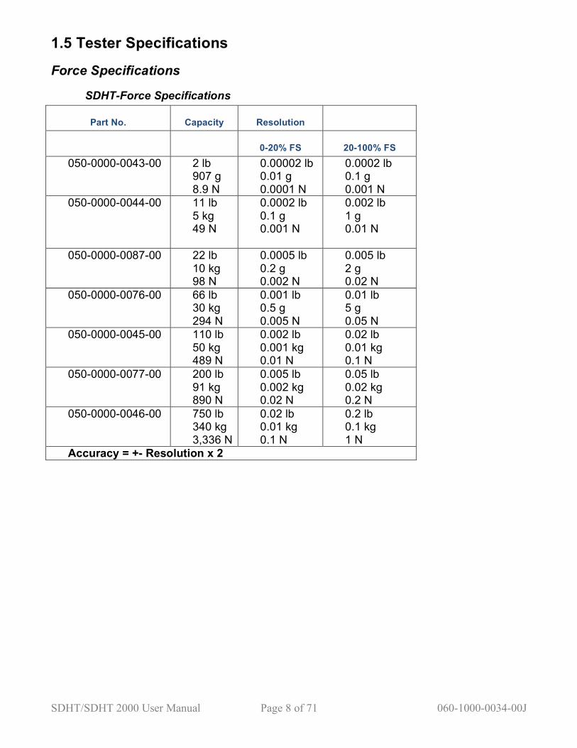
1.5 Tester Specifications
Force Specifications
SDHT-Force Specifications
Part No. Capacity Resolution
0-20% FS 20-100% FS 050-0000-0043-00 2 lb
907 g 8.9 N
0.00002 lb 0.01 g 0.0001 N
0.0002 lb 0.1 g 0.001 N
050-0000-0044-00 11 lb 5 kg 49 N
0.0002 lb 0.1 g 0.001 N
0.002 lb 1 g 0.01 N
050-0000-0087-00 22 lb 10 kg 98 N
0.0005 lb 0.2 g 0.002 N
0.005 lb 2 g 0.02 N
050-0000-0076-00 66 lb 30 kg 294 N
0.001 lb 0.5 g 0.005 N
0.01 lb 5 g 0.05 N
050-0000-0045-00 110 lb 50 kg 489 N
0.002 lb 0.001 kg 0.01 N
0.02 lb 0.01 kg 0.1 N
050-0000-0077-00 200 lb 91 kg 890 N
0.005 lb 0.002 kg 0.02 N
0.05 lb 0.02 kg 0.2 N
050-0000-0046-00 750 lb 340 kg 3,336 N
0.02 lb 0.01 kg 0.1 N
0.2 lb 0.1 kg 1 N
Accuracy = +- Resolution x 2

SDHT/SDHT 2000 User Manual Page 9 of 71 060-1000-0034-00J
SDHT 2000-Force Specifications
Part No. Capacity Resolution
0-20% FS 20-100% FS 025-0000-0394-01 2 lb
907 g 8.9 N
0.00002 lb 0.01 g 0.0001 N
0.0002 lb 0.1 g 0.001 N
025-0000-0394-02 11 lb 5 kg 49 N
0.0002 lb 0.1 g 0.001 N
0.002 lb 1 g 0.01 N
025-0000-0394-03 22 lb 10 kg 98 N
0.0005 lb 0.2 g 0.002 N
0.005 lb 2 g 0.02 N
025-0000-0394-04 66 lb 30 kg 294 N
0.001 lb 0.5 g 0.005 N
0.01 lb 5 g 0.05 N
025-0000-0394-05 110 lb 50 kg 489 N
0.002 lb 0.001 kg 0.01 N
0.02 lb 0.01 lb 0.1 N
025-0000-0394-06 200 lb 91 kg 890 N
0.005 lb 0.002 kg 0.02 N
0.05 lb 0.02 kg 0.2 N
025-0000-0433-00 750 lb 340 kg 3,336 N
0.02 lb 0.01 kg 0.1 N
0.2 lb 0.1 kg 1 N
025-0000-0433-01 1,500 lb 680 kg 6,672 N
0.1 lb 0.05 kg 0.5 N
1 lb 0.5 kg 5 N
025-0000-0433-02 2,000 lb 907 kg 8,896 N
0.1 lb 0.05 kg 0.5 N
1 lb 0.5 kg 5 N
Accuracy = +- Resolution x 2
SDHT/SDHT 2000 User Manual Page 10 of 71 060-1000-0034-00J
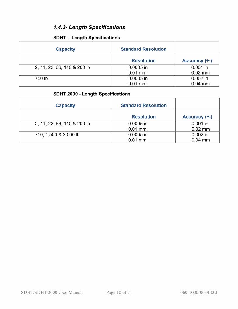
1.4.2- Length Specifications
SDHT - Length Specifications
Capacity Standard Resolution
Resolution Accuracy (+-) 2, 11, 22, 66, 110 & 200 lb 0.0005 in
0.01 mm 0.001 in 0.02 mm
750 lb 0.0005 in 0.01 mm
0.002 in 0.04 mm
SDHT 2000 - Length Specifications
Capacity Standard Resolution
Resolution Accuracy (+-) 2, 11, 22, 66, 110 & 200 lb 0.0005 in
0.01 mm 0.001 in 0.02 mm
750, 1,500 & 2,000 lb 0.0005 in 0.01 mm
0.002 in 0.04 mm
SDHT/SDHT 2000 User Manual Page 11 of 71 060-1000-0034-00J
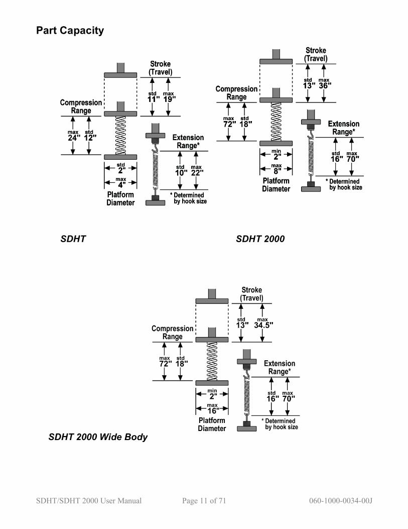
Part Capacity
SDHT SDHT 2000
SDHT 2000 Wide Body
SDHT/SDHT 2000 User Manual Page 12 of 71 060-1000-0034-00J
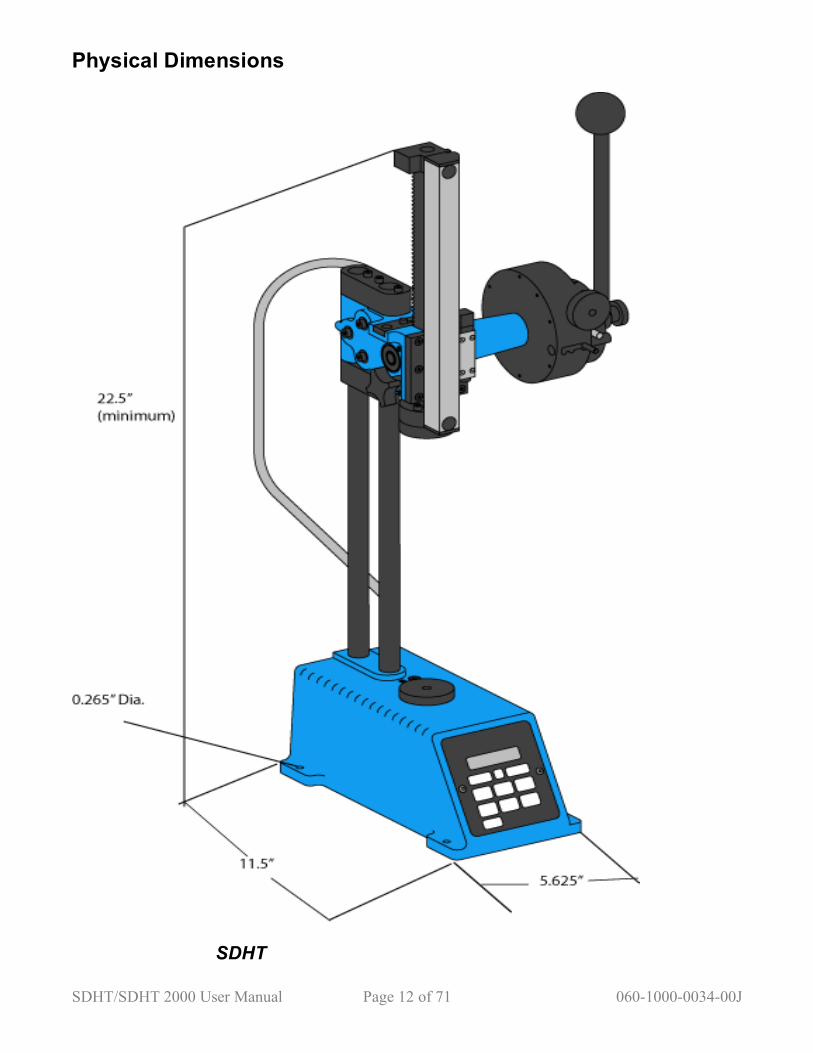
Physical Dimensions
SDHT

SDHT/SDHT 2000 User Manual Page 13 of 71 060-1000-0034-00J
SDHT 2000

SDHT/SDHT 2000 User Manual Page 14 of 71 060-1000-0034-00J
2.0 FIRST STEPS 2.1 Unpacking your SDHT or SDHT 2000
SDHT Unpacking Lay the shipping box on its side and pull out the two styrofoam pieces that encase the SDHT. Check to make sure that you have the following items: 1. SDHT tester 2. Parts list (not shown) 3. Calibration report 4. User manual (this document) 5. Power supply / battery charger 6. Handle knob 7. Handle lock
SHDT 2000 Unpacking The SDHT 2000 ships in a wooden crate. Check to make sure that you have the following items: 1. SDHT 2000 tester 2. Parts list (not shown) 3. Calibration report 4. User manual (this document) 5. Power supply / battery charger 6. Handle rod 7. Handle lock 8. Hand wheel (not shown)

SDHT/SDHT 2000 User Manual Page 15 of 71 060-1000-0034-00J
2.1 Tester Setup Place the tester on a level and stable work area where you can perform compression and extension testing in a comfortable manner. The lower platform should be at a height to allow easy loading, testing and removal of testable items and the displays should be easy to see and read. Make sure the operating location is clean and dry and all materials to be tested are free of dirt and oil. Keep the tester away from any source of liquid. The SDHT can be mounted on a bench for increased stability during testing; mounting holes have been machined into the base.
2.2 Handle Setup The handle rod is used to apply the test force. Insert the handle rod as shown in the images at right. Note that this handle rod can easily be removed and reinstalled at 90° increments for convenient operation. Attach the enclosed handle lock as shown to hold the handle rod in place.
2.3 Power Supply/Battery Charger
The SDHT comes equipped with an internal rechargeable battery pack that allows you to move the tester from place to place. The battery pack is charged with the enclosed battery charger. Connect the power supply / battery charger into the power port in the back of the tester. You can operate the tester while the battery charges.

SDHT/SDHT 2000 User Manual Page 16 of 71 060-1000-0034-00J
2.4 RS 232 Communications Port The SDHT comes equipped with an RS 232 port to send and print data. The RS 232 port allows you to connect the SDHT with a number of output devices including printers, data loggers and computers. The tester should already be set up for communication between itself and a printer. Connect the RS 232 device to the tester using an RS 232 cable. Press
at any time to transmit test data to the device. For more details on the Send feature, see section 3.9, pages 24-25.
SDHT SDHT 2000

SDHT/SDHT 2000 User Manual Page 17 of 71 060-1000-0034-00J
2.5 Stroke Lock—SDHT 2000 The stroke lock prevents the upper platform from moving up or down under load at any position. This feature simplifies setting the length stops, which promotes accurate, repetitive testing at two different lengths. The stroke lock is usable at forces up to 100 lb.
2.6 Range Adjustment Locks These locks secure the upper assembly at any desired position on the support rods to increase or decrease the SDHT’s length range. Your SDHT may be fitted with Quick Release Range Adjust knobs instead of the standard allen screws, allowing for easy setup for varying test material heights.
2.7 SDHT Overload Screws The overload screws are factory set for overload protection. These screws are located on the top of the tester base, adjacent to the lower platform. The screws have been potted at the factory to resist tampering. Tampering with the overload screws will void your warranty.

SDHT/SDHT 2000 User Manual Page 18 of 71 060-1000-0034-00J
2.7 Micro Length Adjust with Built-in Stops The Micro Length Adjust was designed for precise positioning of the upper platform. You can adjust the length in 0.0005” increments at either light or heavy loads. The built-in length stops let you perform a repeatable two-point test.
2.7.1 Micro Length Adjust—SDHT
Raise or lower the upper platform to the desired approximate height using the handle rod, then rotate the sliding stop pin to the right to engage. At this point, the handle rod becomes unusable. Rotate the knob clockwise to lower the platform or counterclockwise to raise it. You can now “fine-tune” the upper platform much more precisely.
2.7.2 Micro Length Adjust—SDHT 2000
The SDHT 2000 gearbox accommodates two different torque ratios--High Torque and Normal. Place the hand wheel [inset] on the High Torque pin for heavy loads and on the Normal pin for lighter loads.
To engage, raise or lower the upper platform to the desired approximate height using the handle rod. Pull the Engaging Pin out toward you with one hand and rotate the entire gearbox assembly to the right to engage. Push the Engaging Pin into the internal locking hole. You can now use the hand wheel on the High Torque pin or the Normal pin for operation.
SDHT/SDHT 2000 User Manual Page 19 of 71 060-1000-0034-00J
2.8 Built-in Length Stops The procedure below describes how to use the Micro Length Adjust with Built-in Stops for a test with two test points. This procedure applies to both the SDHT and SDHT 2000. 1. Move the Stop Pin fully to the right. 2. Loosen both the outer and inner stop Dial Screws. 3. Set the Outer Stop Dial to the longer test length for compression tests. Set it to the shorter test length for extension tests. Tighten the outer Dial Screw. 4. Release the load, then load the sample to the Outer Stop Point. View the length display to verify that you stopped at test point 1. Adjust if needed. 5. Release the load and slide the Stop Pin one click to the left. 6. Set the Inner Stop Dial to the shorter test length for compression tests. Set it to the longer test length for extension tests. Tighten the inner Dial Screw. 7. Release the load then load the sample to the Inner Stop Point. View the length display to verify that you stopped at test point 2. Adjust if needed. 8. Perform any two-point test. 9. For normal operation, disengage the length stops by moving the Stop Pin fully to the left.
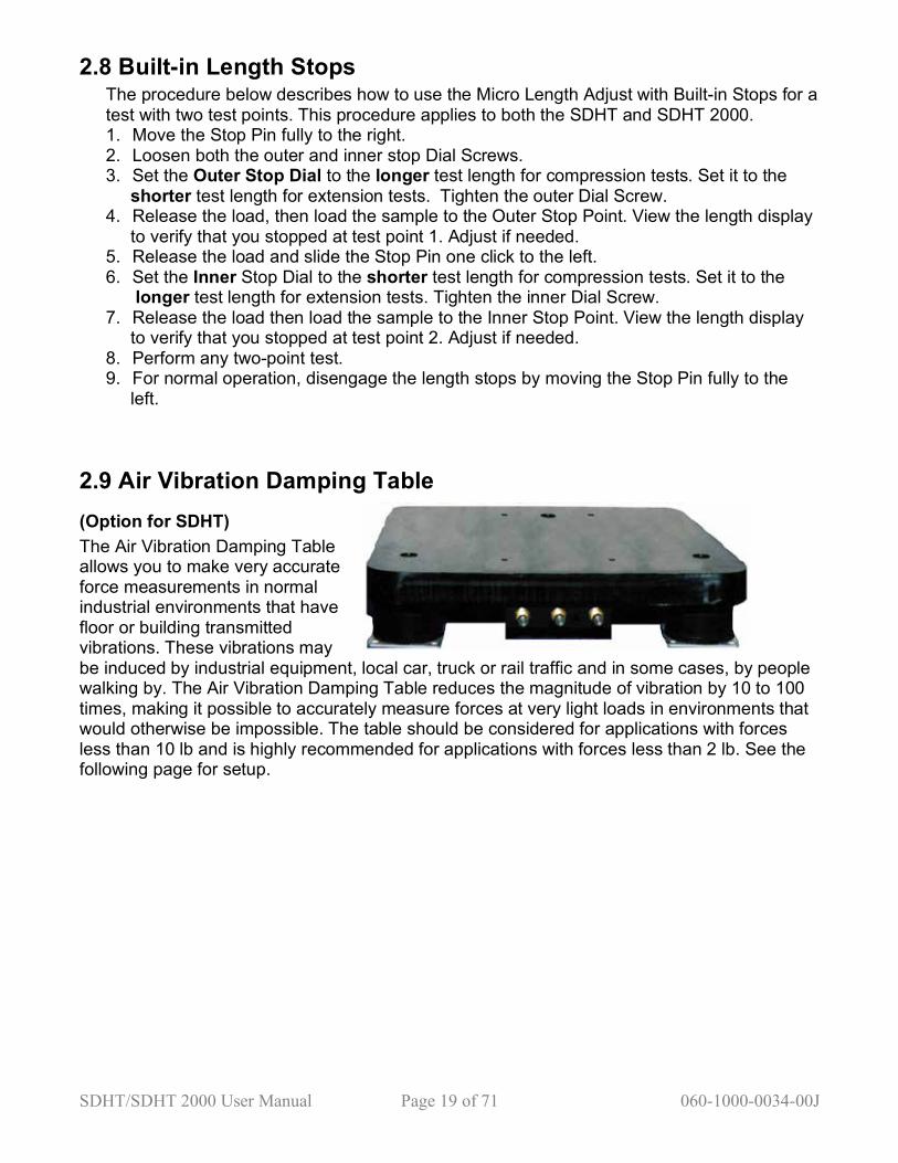
2.9 Air Vibration Damping Table (Option for SDHT) The Air Vibration Damping Table allows you to make very accurate force measurements in normal industrial environments that have floor or building transmitted vibrations. These vibrations may be induced by industrial equipment, local car, truck or rail traffic and in some cases, by people walking by. The Air Vibration Damping Table reduces the magnitude of vibration by 10 to 100 times, making it possible to accurately measure forces at very light loads in environments that would otherwise be impossible. The table should be considered for applications with forces less than 10 lb and is highly recommended for applications with forces less than 2 lb. See the following page for setup.

SDHT/SDHT 2000 User Manual Page 20 of 71 060-1000-0034-00J
Air Vibration Damping Table Setup 1. Mount the SDHT on the table, using the four, 1/4-20 x 3/4” bolts (included.) 2. Turn three front air valves to Off position (clockwise). 3. Connect a pneumatic air line to the air input valve. 4. Turn air valves counterclockwise to pressurize each mount so that the distance between the bottom of the air vibration damping table and the work bench is 2.5”. 5. Place a leveling instrument on the table and adjust the air pressure equally until the table is level.

SDHT/SDHT 2000 User Manual Page 21 of 71 060-1000-0034-00J
3.0 FEATURES AND CONTROLS 3.1 Buttons
Menu selection button used by the Options menu.
Switches between various user-selected options.
Menu selection button used by the options menu.
Returns the length reading to 0.
Returns the force reading to 0.
Switches between three test modes: Manual Mode: Always displays current force reading. Peak Mode: Displays the maximum or minimum force reading. Press
to reset. Two Point with Rate Mode: Records two test points, then calculates the spring rate.

SDHT/SDHT 2000 User Manual Page 22 of 71 060-1000-0034-00J
Switches between various English and Metric units of measure. Unused units can be removed via the user setup menu.
Saves data to an internal 1,800- test-point data logger. Saved tests can be sent to a printer or computer at a later time.
Transmits data via the RS 232 port to an external data logger, printer or computer. You can cancel sending data by pressing Send again.
Turns the SDHT on. Also used as an Enter button in the Option menu and resets the Peak or Two Point with Rate test modes.
Shuts the SDHT off.
3.2 Turning on the SDHT Press to turn on the SDHT. The Load and Length LEDs will flash briefly. Next, the software version number will appear (this information may be required if your SDHT ever requires service.) Next, the load cell capacity will be displayed. Finally, the force and reading measurement units will be displayed. The length will not be displayed until the length initialization is performed.
3.3 Turning off the SDHT
Press to ensure the tester is in Test mode and not in the Options menu. Press the
button. You can also press the key until the Offset/Power screen appears. Press TWICE to turn off power to the tester.
3.4 Backlight Off and Power Off Timers Your SDHT comes equipped with a backlight timer and a power off timer to conserve battery life. The timers are factory set, but can be changed to meet your requirements. See Section 5.7.3, and 5.7.8. These timers start when the tester sits idle (no length movement or buttons pushed). When a backlighting timeout occurs, the screen backlight will shut off until a button is pushed or there is length movement. At this point, you may resume testing. When a power
SDHT/SDHT 2000 User Manual Page 23 of 71 060-1000-0034-00J
timeout occurs, the tester automatically turns off. Should the power turn off, you must press
to reinitialize the length and force.
3.5 Selecting Measurement Units Measurement units can be displayed in the following pairs: (in/lb), (mm/N), (mm/g), (in/g),
(mm/kg), (in/kg), or (in/oz). Press to toggle through the different units and view them on the display. Note: Different units can be selected, but the first unit selected will be used if there is test data stored in memory or if a printout has started. See5.1 for more information on storing data.
3.6 Storing Test Data
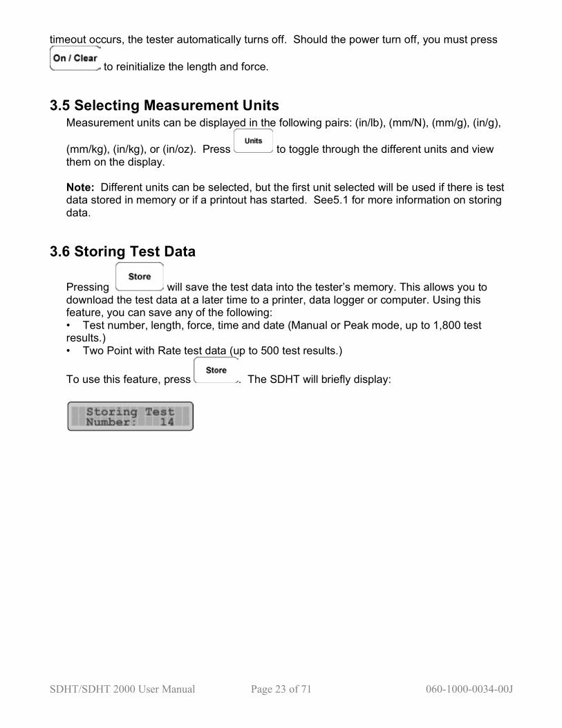
Pressing will save the test data into the tester’s memory. This allows you to download the test data at a later time to a printer, data logger or computer. Using this feature, you can save any of the following: Test number, length, force, time and date (Manual or Peak mode, up to 1,800 test
results.) Two Point with Rate test data (up to 500 test results.)
To use this feature, press . The SDHT will briefly display:
SDHT/SDHT 2000 User Manual Page 24 of 71 060-1000-0034-00J
3.7 Force and Length Initialization The force and length of the tester must be initialized (or zeroed) at a reference point prior to any testing. The following sections describe how to perform the initialization for compression and extension testing.
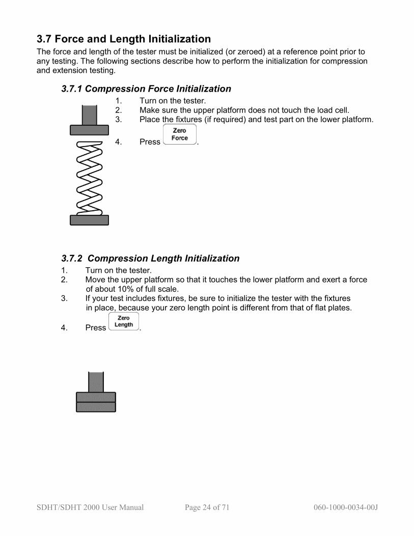
3.7.1 Compression Force Initialization 1. Turn on the tester. 2. Make sure the upper platform does not touch the load cell. 3. Place the fixtures (if required) and test part on the lower platform.
4. Press .
3.7.2 Compression Length Initialization 1. Turn on the tester. 2. Move the upper platform so that it touches the lower platform and exert a force of about 10% of full scale. 3. If your test includes fixtures, be sure to initialize the tester with the fixtures in place, because your zero length point is different from that of flat plates.
4. Press .

SDHT/SDHT 2000 User Manual Page 25 of 71 060-1000-0034-00J
3.7.3 Extension Force Initialization 1. Turn on the tester. 2. Install the extension hooks. 3. Move the upper platform so that the hooks are not coupled and no force is applied to the lower platform.
4. Press .
3.7.4 Extension Length Initialization 1. Turn on the tester. 2. Install the extension hooks and couple them as shown in the diagram. 3. Move the upper platform up until a force of about 10% of full scale is exerted.
4. Press .
SDHT/SDHT 2000 User Manual Page 26 of 71 060-1000-0034-00J
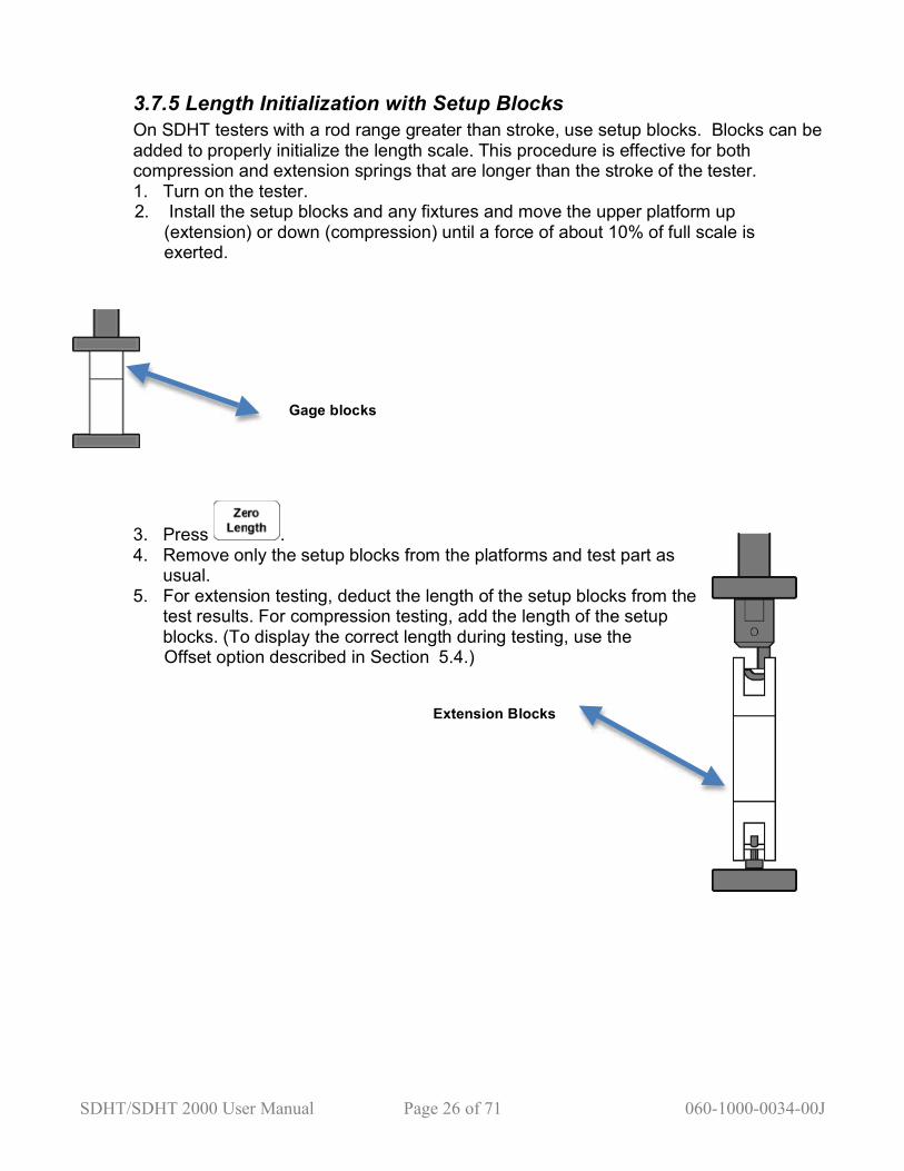
3.7.5 Length Initialization with Setup Blocks On SDHT testers with a rod range greater than stroke, use setup blocks. Blocks can be added to properly initialize the length scale. This procedure is effective for both compression and extension springs that are longer than the stroke of the tester. 1. Turn on the tester.
2. Install the setup blocks and any fixtures and move the upper platform up (extension) or down (compression) until a force of about 10% of full scale is exerted.
Gage blocks
3. Press . 4. Remove only the setup blocks from the platforms and test part as usual. 5. For extension testing, deduct the length of the setup blocks from the test results. For compression testing, add the length of the setup blocks. (To display the correct length during testing, use the
Offset option described in Section 5.4.)
Extension Blocks
SDHT/SDHT 2000 User Manual Page 27 of 71 060-1000-0034-00J
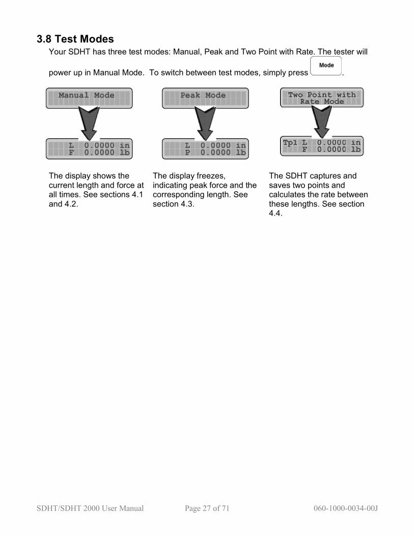
3.8 Test Modes Your SDHT has three test modes: Manual, Peak and Two Point with Rate. The tester will
power up in Manual Mode. To switch between test modes, simply press .
The display shows the current length and force at all times. See sections 4.1 and 4.2.
The display freezes, indicating peak force and the corresponding length. See section 4.3.
The SDHT captures and saves two points and calculates the rate between these lengths. See section 4.4.

SDHT/SDHT 2000 User Manual Page 28 of 71 060-1000-0034-00J
3.9 Sending Data The SDHT comes equipped with an RS 232 data communications port. This port sends data to a number of output devices including printers, data loggers and computers. The RS 232 communication settings should already be formatted to send the data to your particular output device (factory set for a printer). To make changes to these settings, see sections 5.7.1 and 5.7.2. Verify that the SDHT is connected the RS 232 device via an RS 232
cable. Press at any time to output the testing information via your RS 232 device.
We highly recommend using the optional LSI-provided inkjet printer with your SDHT (part # 025-0000-0464-00.)

SDHT/SDHT 2000 User Manual Page 29 of 71 060-1000-0034-00J
3.9.1 Printout Examples The examples illustrate the SDHT’s Two Point with Rate statistical printout.

SDHT/SDHT 2000 User Manual Page 30 of 71 060-1000-0034-00J
3.9.2 Sending Current Data Information shown on the display is considered current test data.
1. Press . The data is sent to the RS 232 device:
2. To send more data, press again.
3. To end the test cycle and print a
summary of the data, press .
4. Press . A summary of previous data is sent to the RS 232 device, which includes mean, standard deviation, maximum, minimum and range.
3.9.3 Sending Stored Test Data This function sends previously stored test data to an RS 232 device. You have a choice of sending all data or just the current (present) data. If you decide to send the stored data, you will have the option of saving or clearing the data from memory.
1. Press .
2. Press to send the stored test data or to send current test data. If the print summary option is enabled, (See section 5.7.1, page 40-42), a summary will be created when the stored data is sent. If no data is in memory, only the current data will be sent. If stored data was sent, the SDHT will display:
3.
Press to clear the test data, or to keep the test data.

SDHT/SDHT 2000 User Manual Page 31 of 71 060-1000-0034-00J
3.9.4 Retrieving Test Data via Computer When a computer is connected to the SDHT, it can ask the tester for the present length and force data by sending an ASCII string. The tester will respond by sending the requested data back to the computer. ASCII string “DRP <cr>” requests the current length and force data from the
tester. ASCII string “DRS <cr>” requests all stored test data from the tester.
When <cr> is used, it is meant to simulate a carriage return, or the Enter or Return key.
3.9.5 Viewing Test Data on a Computer
The following example shows the data format that is sent each time is pressed:

SDHT/SDHT 2000 User Manual Page 32 of 71 060-1000-0034-00J
3.9.6 Description of data format output Heading The first three lines of data contain non-numeric data. Line 1 identifies the type of device sending the data. Line 2 identifies the test mode used to find the test data. Line 3 identifies the measurement units used. Example: DVDHT Device (DV) sending the test data is a DHT SCM Specified command (SC) is Manual mode MUIL Measurement units (MU) is inch / lb Count If a single test is sent, the test count will always be 0. If stored tests are sent, the test count will start with 1 and continue to the highest test number. Date Date of the test. (MM/DD/YY, or as specified in the User Setup option) Time Time of the test. (HH:MM:SS, or as specified in the User Setup option) Tab A tab character will be inserted after the time is sent. This is for SDHTs connected to a data logger such as DataMyte. It is required to read the date and time as a remark. Length The length reading. Force The force reading. Communications parameters See section 5.7.2.
SDHT/SDHT 2000 User Manual Page 33 of 71 060-1000-0034-00J
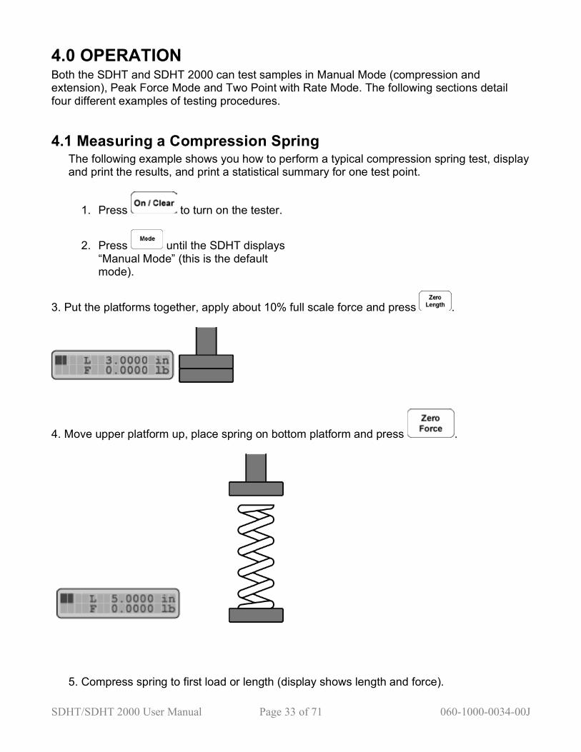
4.0 OPERATION Both the SDHT and SDHT 2000 can test samples in Manual Mode (compression and extension), Peak Force Mode and Two Point with Rate Mode. The following sections detail four different examples of testing procedures.
4.1 Measuring a Compression Spring The following example shows you how to perform a typical compression spring test, display and print the results, and print a statistical summary for one test point.
1. Press to turn on the tester.
2. Press until the SDHT displays “Manual Mode” (this is the default mode).
3. Put the platforms together, apply about 10% full scale force and press .
4. Move upper platform up, place spring on bottom platform and press .
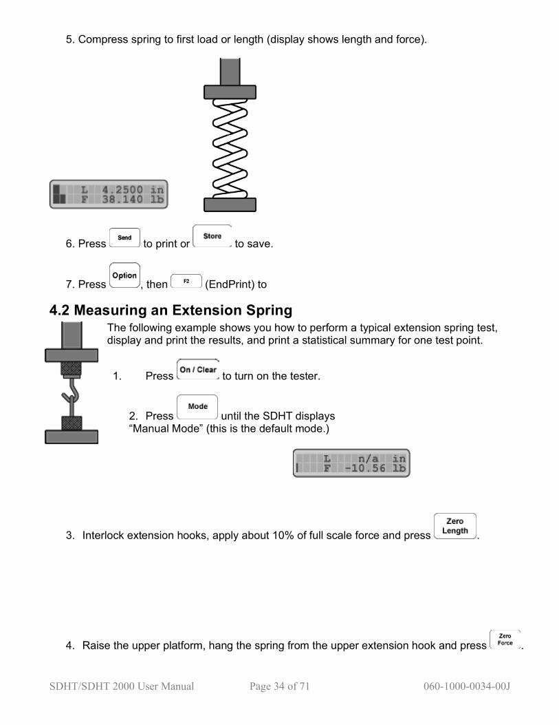
5. Compress spring to first load or length (display shows length and force).
SDHT/SDHT 2000 User Manual Page 34 of 71 060-1000-0034-00J
4.2 Measuring an Extension Spring The following example shows you how to perform a typical extension spring test, display and print the results, and print a statistical summary for one test point.
5. Compress spring to first load or length (display shows length and force).
6. Press to print or to save.
7. Press , then (EndPrint) to
1. Press to turn on the tester.
2. Press until the SDHT displays “Manual Mode” (this is the default mode.)
3. Interlock extension hooks, apply about 10% of full scale force and press .
4. Raise the upper platform, hang the spring from the upper extension hook and press .

SDHT/SDHT 2000 User Manual Page 35 of 71 060-1000-0034-00J
5. Extend the spring to first load or length (display shows length and force.)
6. Press to print or to save.
7. Press, then (EndPrint) to print the statistical summary.

SDHT/SDHT 2000 User Manual Page 36 of 71 060-1000-0034-00J
4.3 Measuring Peak Force The following example shows you how to measure the peak force, display and print the results, and print a statistical summary for one test point.
1. Press to turn on the tester.
2. Install the fixtures that will hold the sample.
3. Press until the SDHT displays Peak Mode.”
4. Load the sample and press .
5. Optionally, apply about 10% of full scale force and press .

SDHT/SDHT 2000 User Manual Page 37 of 71 060-1000-0034-00J
6. Extend or compress the sample to the desired length, past the peak force point of the sample.
7. The SDHT will display the maximum applied force.

SDHT/SDHT 2000 User Manual Page 38 of 71 060-1000-0034-00J
8. Press to print, to save, or to reset to try the test again.
9. Press , then (EndPrint) to print the statistical summary.
Note: Diagrams show a sample extension peak force test. A compression peak force test would be very similar.
4.4 Measuring Spring Rate The following example shows you how to perform a typical compression spring test, display and print the results, and print a statistical summary for two test points. The instructions below are for a compression spring, but the steps are very similar for an extension spring. Refer to section 4.2 for mounting instructions.
4.4.1 Spring Rate - Print or Store Data Directly
1. Press to turn on the tester.
2. Put platforms together, and press .
3. Press until the SDHT displays “Two Point with Rate Mode.” 4. Raise the upper platform, place the spring on the lower platform and press
.
5. Compress the spring to the first force or length point and press or
to capture test point 1.
6. Compress the spring to the second force or length point and press or
to capture test point 2. 7. The spring rate is not displayed, but is printed or stored.
8. Press then (EndPrint) to print the statistical summary.

SDHT/SDHT 2000 User Manual Page 39 of 71 060-1000-0034-00J
4.4.2 Spring Rate - Display Data
1. Press to turn on the tester.
2. Put platforms together, and press
.
3. Press until the SDHT displays “Two Point with Rate Mode”.
4. Raise the upper platform, place the spring on the lower platform and press .
5. Compress the spring to the first force or length point and press to capture test point 1.
(Test Point 1)
SDHT/SDHT 2000 User Manual Page 40 of 71 060-1000-0034-00J
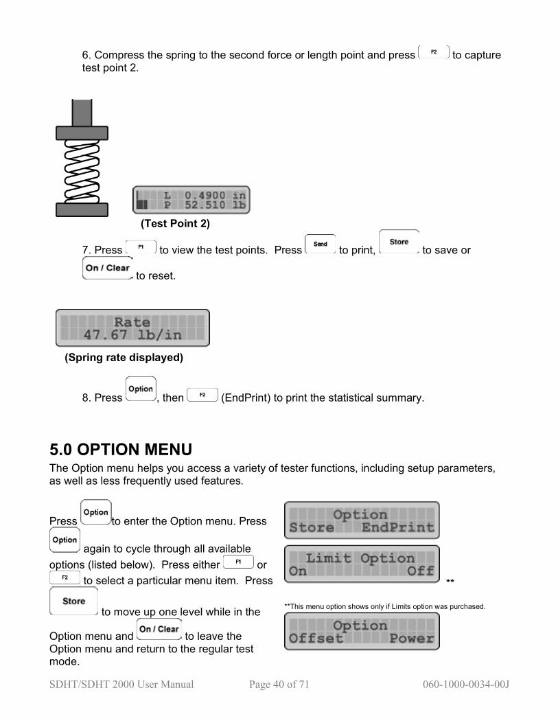
6. Compress the spring to the second force or length point and press to capture test point 2.
(Test Point 2)
7. Press to view the test points. Press to print, to save or
to reset.
(Spring rate displayed)
8. Press , then (EndPrint) to print the statistical summary.
5.0 OPTION MENU The Option menu helps you access a variety of tester functions, including setup parameters, as well as less frequently used features.
Press to enter the Option menu. Press
again to cycle through all available options (listed below). Press either or
to select a particular menu item. Press
to move up one level while in the
Option menu and to leave the Option menu and return to the regular test mode.
** **This menu option shows only if Limits option was purchased.

SDHT/SDHT 2000 User Manual Page 41 of 71 060-1000-0034-00J
The following sections have detailed descriptions of the menu items.
5.1 Store Store lets you view all test points, clear a displayed test point or clear all test points.
1. Press until you see:
2. Press to select Store.
ed, the SDHT will display:
3. Press or to scroll through and view the test data.
4. Press . The SDHT then asks to delete the current test point. Press to
delete this test point or to cancel and return to the current test point.

SDHT/SDHT 2000 User Manual Page 42 of 71 060-1000-0034-00J
5. When you see the above displayed, press again. The SDHT will ask to delete ALL test points :
6. Press to delete ALL test points, to go back to deleting only the current test
point, or to cancel and return to your current test point.
5.2 EndPrint The EndPrint option allows you to print statistical summary data such as the mean, standard deviation, maximum, minimum and range at the end of testing.
1. Press until you see:
2. Press to select EndPrint.
connected, the SDHT will display:
print the statistical summary and the SDHT will display:
SDHT/SDHT 2000 User Manual Page 43 of 71 060-1000-0034-00J
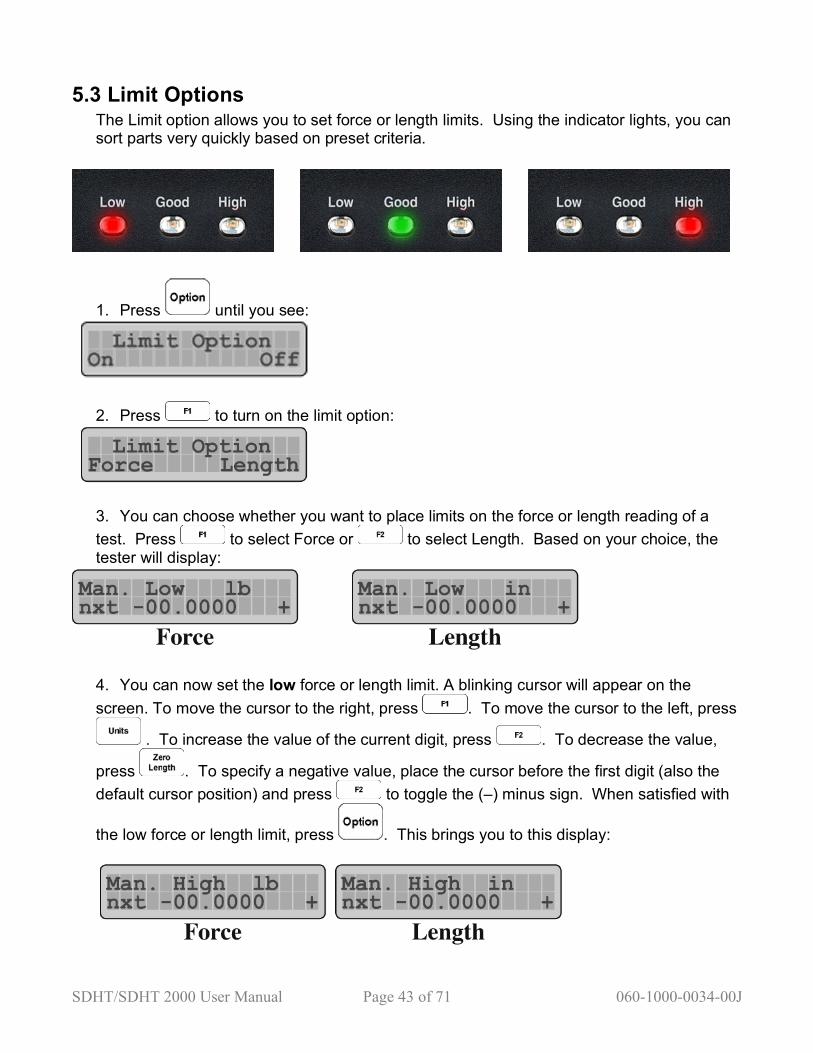
5.3 Limit Options The Limit option allows you to set force or length limits. Using the indicator lights, you can sort parts very quickly based on preset criteria.
1. Press until you see:
2. Press to turn on the limit option:
3. You can choose whether you want to place limits on the force or length reading of a test. Press to select Force or to select Length. Based on your choice, the tester will display:
4. You can now set the low force or length limit. A blinking cursor will appear on the screen. To move the cursor to the right, press . To move the cursor to the left, press
. To increase the value of the current digit, press . To decrease the value,
press . To specify a negative value, place the cursor before the first digit (also the default cursor position) and press to toggle the (–) minus sign. When satisfied with
the low force or length limit, press . This brings you to this display:
SDHT/SDHT 2000 User Manual Page 44 of 71 060-1000-0034-00J
5. You can now set the high force or length limit. Refer to the previous step for setting the
value. When done, press to go back to the low force or length limit or to save the limit values and return to normal test mode.
6. While testing with the limit option enabled, the Low, Good and High limit lights on your SDHT will alert you to the test condition of the part. Good parts will return a green light and out-of-spec parts—too low or too high--will display red lights.
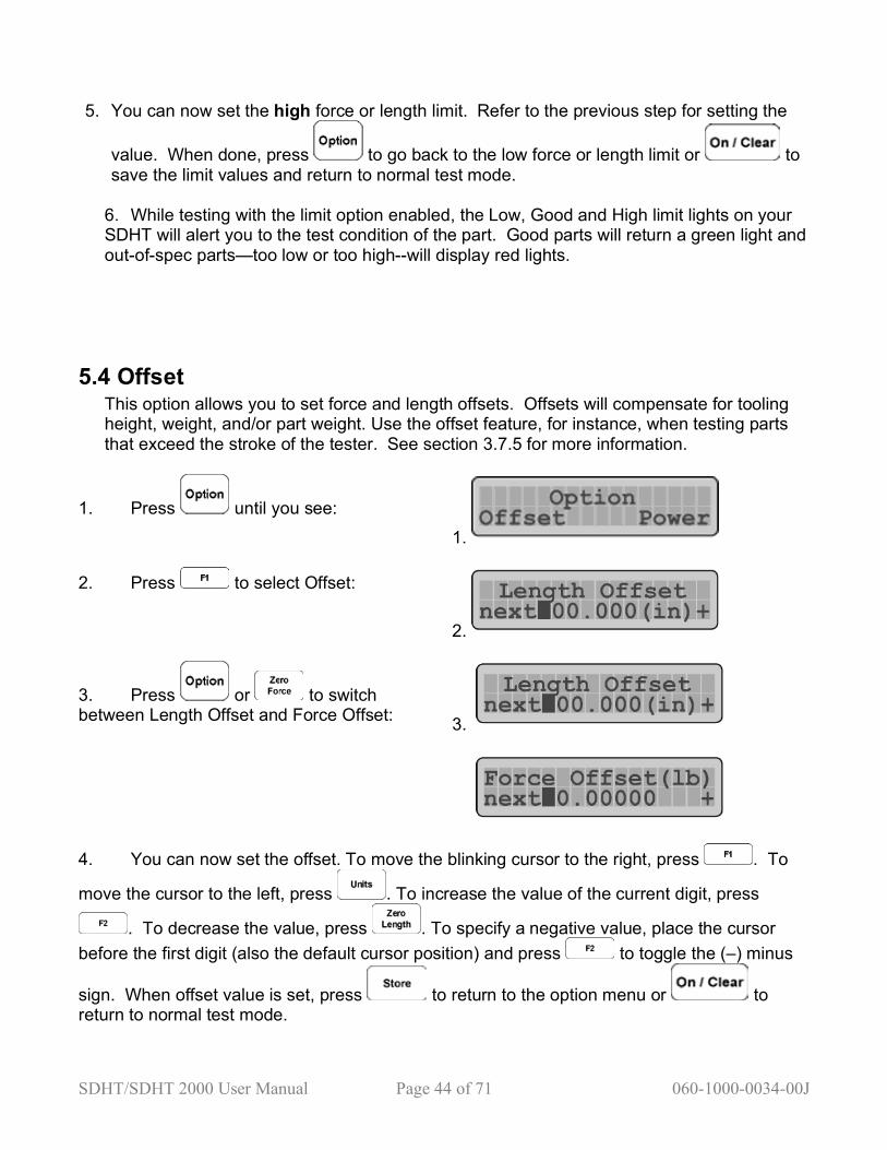
5.4 Offset This option allows you to set force and length offsets. Offsets will compensate for tooling height, weight, and/or part weight. Use the offset feature, for instance, when testing parts that exceed the stroke of the tester. See section 3.7.5 for more information.
1. Press until you see:
1.
2. Press to select Offset:
2.
3. Press or to switch between Length Offset and Force Offset: 3.
4. You can now set the offset. To move the blinking cursor to the right, press . To
move the cursor to the left, press . To increase the value of the current digit, press
. To decrease the value, press . To specify a negative value, place the cursor before the first digit (also the default cursor position) and press to toggle the (–) minus
sign. When offset value is set, press to return to the option menu or to return to normal test mode.

SDHT/SDHT 2000 User Manual Page 45 of 71 060-1000-0034-00J
5.5 Power: Turning off the SDHT from the Options Menu
Press until this screen appears:
Press to select Power:
Press to turn off power to the tester. You will see a screen that tells you your data is being saved.
If you are not in the Options menu, simply press the button.
5.6 Calibration Check This option allows you to verify the calibration of the SDHT based on shunt numbers set at the factory. This information is recorded on the traceable report included with the tester.
1. Press until you see: 1.
2. Press to select Cal Check:
2.
3. If your tester is an SDHT, press to select Panel. If your tester is an SDHT 2000, press to select Load Cell. You will see the following sequence of screens:
3.
4. The number following the S is the shunt value. The number following the F is the force value. Press or to view the zero reading:
4.

SDHT/SDHT 2000 User Manual Page 46 of 71 060-1000-0034-00J
5. If the force value or the zero value are not within load cell tolerances, the tester must be
recalibrated. Press to exit to normal test mode.
5.7 User Setup You can use the User Setup menu to customize your SDHT. For example, you can choose power options, enter your company name, and more.
1. Press to enter the Option menu. Scroll through the Options menu by pressing until you see:
2. Press to select User Setup. You will see the following sequence of screens:
(Note: If you press , you will return to the Options menu.)
3. To continue and enter the passcode, you must press the following buttons:
You are now in the SDHT’s User Setup menu:
4. Press to cycle through all the available options, which are shown at right.
Press to return to regular test mode.

SDHT/SDHT 2000 User Manual Page 47 of 71 060-1000-0034-00J
5.7.1 User Setup—Getting Ready to Print a Report from the RS 232
This option allows you to set up the communications port. This menu has two options: Report and Data. The Report option allows you to setup the SDHT to print the report. The Data option allows you to establish the communication link between the SDHT and a data logger or other RS 232 device.
1. Press to select RS232. You should see a screen that says:
2. You can now choose between sending data and printing a report. Press to
choose Report, or to choose Data. Choose Report and press to continue to the next screen:
3. Press for Yes; for No. Press to continue to the next screen:
SDHT/SDHT 2000 User Manual Page 48 of 71 060-1000-0034-00J
4. You may now choose a Standard or Full Stats report. Press either or to
toggle between Full Stats and Standard.
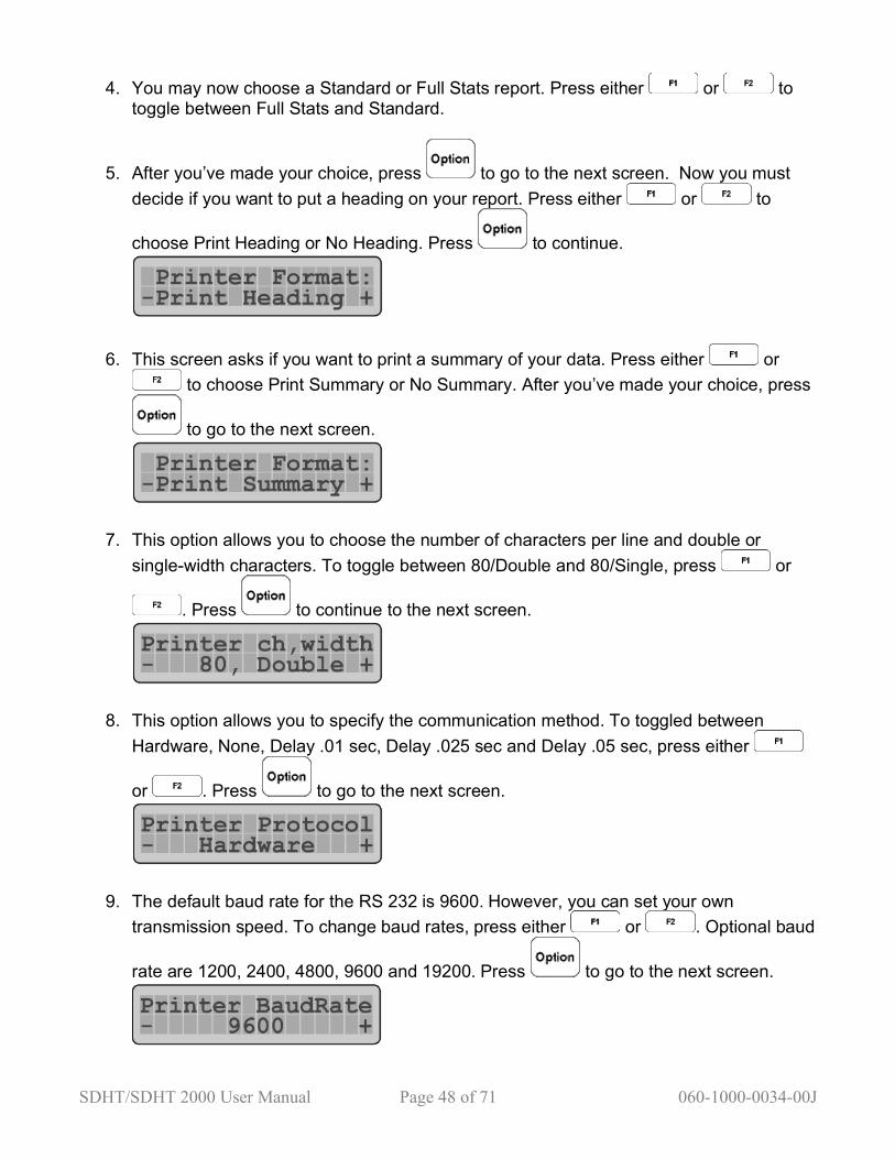
5. After you’ve made your choice, press to go to the next screen. Now you must decide if you want to put a heading on your report. Press either or to
choose Print Heading or No Heading. Press to continue.
6. This screen asks if you want to print a summary of your data. Press either or to choose Print Summary or No Summary. After you’ve made your choice, press
to go to the next screen.
7. This option allows you to choose the number of characters per line and double or single-width characters. To toggle between 80/Double and 80/Single, press or
. Press to continue to the next screen.
8. This option allows you to specify the communication method. To toggled between Hardware, None, Delay .01 sec, Delay .025 sec and Delay .05 sec, press either
or . Press to go to the next screen.
9. The default baud rate for the RS 232 is 9600. However, you can set your own transmission speed. To change baud rates, press either or . Optional baud
rate are 1200, 2400, 4800, 9600 and 19200. Press to go to the next screen.

SDHT/SDHT 2000 User Manual Page 49 of 71 060-1000-0034-00J
10. To choose between Plain Paper (8.5” x 11”) or Roll Feed (for 4” thermal printer paper),
press or . Press to go to the next screen.
11. You can now set the number of lines per page. Default value is 66 lines per page. To move the blinking cursor to the right, press . Press to increase or the
number of lines. Press to decrease the number of lines. When the desired
number of lines has been set, press to continue.
12. You are now ready to select a printer. To choose an LSI-provided printer (Okidata impact printer—Oki-1F/1E, or Epson inkjet printer—Epson-0E/14) or your own printer
(Other), press or . Press to save your selections and exit the User Setup Option.
5.7.2 User Setup—Getting Ready to Transmit Data via the RS 232 The Data option allows you to set the communications link between the SDHT and a data logger or other RS 232 device.
1. Start at the Options menu and select:
2. Press to access this screen:
3. Press to choose Data:

SDHT/SDHT 2000 User Manual Page 50 of 71 060-1000-0034-00J
Then press to continue to the next screen.
4. To toggle between Yes and No, press or . Press to continue to the next screen.
5. This screen asks if you want to put a heading on your data before you send it. Press
or to toggle between Send Heading and No Heading. Press to go on.
6. This screen asks if you want to send a Test Count. Press or to toggle
between Send Count and No Test Count. Press to go on.
7. This function adds the current date to the report. Press or to toggle
between Send Date and No Date. Press to go on.
8. This function adds the current time to the report. Press or to toggle
between Send Time and No Time. Press to go on.
9. The RS 232 device to which your SDHT is connected may require a tab character. To toggle between Send Tab Char and No Tab Char, press or . To continue,
press .

SDHT/SDHT 2000 User Manual Page 51 of 71 060-1000-0034-00J
10. Sometimes, you want to send only the length or force measurements to a data logger.
Press or to toggle between Send Length and No Length. Press to
go on. Press to move to the Send Force screen. Press or to toggle
between Send Force and No Force. Press to go on.
11. This option allows you to specify the communication method. To toggle between Hardware, Delay .05 sec, Delay .025 sec, Delay .01 sec, and None, press or
. Press to go on to the next step.
12. The default baud rate for the RS 232 is 9600. However, you can set your own transmission speed. To change baud rates, press either or . Optional baud rate are 1200, 2400, 4800, 9600 and 19200.
13. Press to save your information and exit.
5.7.3 User Setup—Power Timeout The Power option helps prolong the SDHT’s battery life. With this option, you can set the automatic timer to turn off the battery power when no activity is detected for a set value. Go to the User Setup screen.
Press to select Power. This example shows a time of 90 hours and 20 minutes. To
move the blinking cursor to the right, press . To move the cursor to the left press . To increase the value of the digit highlighted by the cursor, press . To decrease the

SDHT/SDHT 2000 User Manual Page 52 of 71 060-1000-0034-00J
value, press . When the desired value is set, Press to save and exit to normal test mode.
5.7.4 User Setup—Dampening Dampening averages the force measurements to eliminate the noise in the display caused by vibration. Dampening will slow the measurement process. LSI recommends setting dampening to the minimum level necessary to achieve a stable, readable display. Go to the User Setup screen.
Press to get to the Dampening screen.
To switch between None, Low, Medium and High press or . Press to save and return to normal test mode.
5.7.5 User Setup—Date and Time You can adjust the date and time to fit the standard your company uses.
1. Go to the User Setup screen.
2. Press to get to the Dampening screen.

SDHT/SDHT 2000 User Manual Page 53 of 71 060-1000-0034-00J
3. Press to select Date.
4. The default format is MM/DD/YY. To switch between Month/Day/Year, Year/Month/Day or
Day/Month/Year, press or . Press to continue to the next screen. 5. Now you can change the date. To move the blinking cursor to the right, press . To
move the cursor to the left, press . To increase the value of the blinking digit, press
. To decrease the value, press . Press option to move to the next screen.
6. You can set the clock on the SDHT to a 12-hour or 24-hour clock. The default format is a 12-hour clock. To switch between the 12-hour clock and the 24-hour clock, press or
. Press to continue to the next screen.
7. Now you can change the time. To move the blinking cursor to the right, press . To
move the cursor to the left, press . To increase the value of the blinking digit, press
. To decrease the value, press . Press store to save your settings. You will automatically return to normal test mode.
5.7.6 User Setup—Company Name You can put your company name into your SDHT—a great theft deterrent.
Go to the User Setup screen. Use to get to the Company screen.
SDHT/SDHT 2000 User Manual Page 54 of 71 060-1000-0034-00J
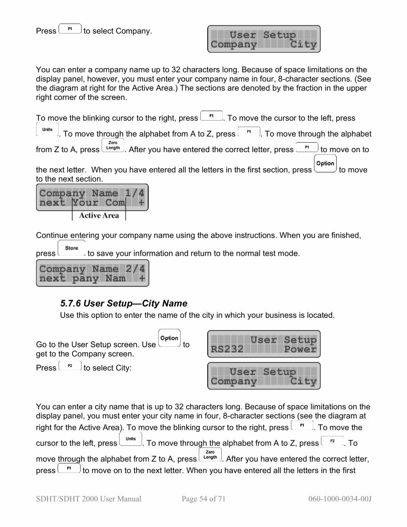
Press to select Company.
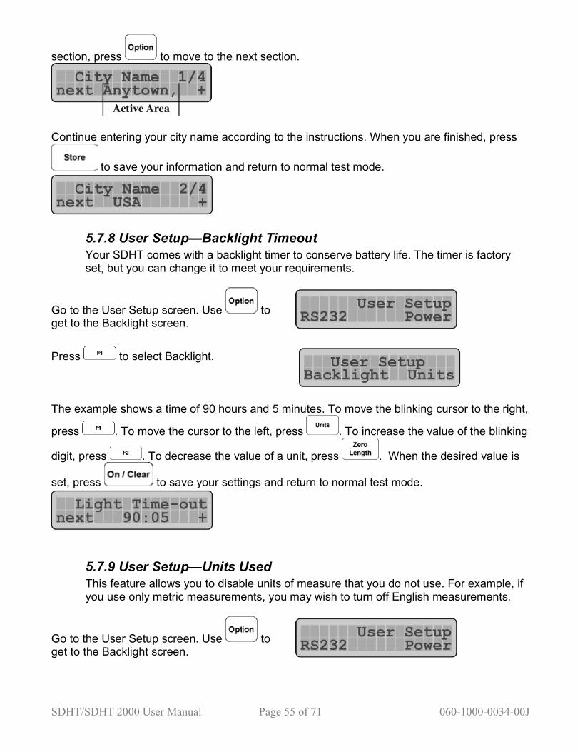
You can enter a company name up to 32 characters long. Because of space limitations on the display panel, however, you must enter your company name in four, 8-character sections. (See the diagram at right for the Active Area.) The sections are denoted by the fraction in the upper right corner of the screen. To move the blinking cursor to the right, press . To move the cursor to the left, press
. To move through the alphabet from A to Z, press . To move through the alphabet
from Z to A, press . After you have entered the correct letter, press to move on to
the next letter. When you have entered all the letters in the first section, press to move to the next section.
Continue entering your company name using the above instructions. When you are finished,
press to save your information and return to the normal test mode.
5.7.6 User Setup—City Name Use this option to enter the name of the city in which your business is located.
Go to the User Setup screen. Use to get to the Company screen. Press to select City:
You can enter a city name that is up to 32 characters long. Because of space limitations on the display panel, you must enter your city name in four, 8-character sections (see the diagram at right for the Active Area). To move the blinking cursor to the right, press . To move the
cursor to the left, press . To move through the alphabet from A to Z, press . To
move through the alphabet from Z to A, press . After you have entered the correct letter, press to move on to the next letter. When you have entered all the letters in the first
SDHT/SDHT 2000 User Manual Page 55 of 71 060-1000-0034-00J
section, press to move to the next section.
Continue entering your city name according to the instructions. When you are finished, press
to save your information and return to normal test mode.
5.7.8 User Setup—Backlight Timeout Your SDHT comes with a backlight timer to conserve battery life. The timer is factory set, but you can change it to meet your requirements.
Go to the User Setup screen. Use to get to the Backlight screen.
Press to select Backlight.
The example shows a time of 90 hours and 5 minutes. To move the blinking cursor to the right,
press . To move the cursor to the left, press . To increase the value of the blinking
digit, press . To decrease the value of a unit, press . When the desired value is
set, press to save your settings and return to normal test mode.
5.7.9 User Setup—Units Used This feature allows you to disable units of measure that you do not use. For example, if you use only metric measurements, you may wish to turn off English measurements.
Go to the User Setup screen. Use to get to the Backlight screen.

SDHT/SDHT 2000 User Manual Page 56 of 71 060-1000-0034-00J
Press to choose Units.
To scroll through the various units of measure, press . Press or to toggle between Use and Don’t Use for each unit and turn them on or off. When all desired units have
been enabled or disabled, press to save and return to normal test mode.
5.7.10—User Setup—First Peak Drop This feature allows you to set the first peak mode drop-off setting.
1. Go to the User Setup screen. Use to get to the 1st Peak Filter screen.
2. Press to select 1st Peak.
3. This example indicates a drop of 0.0002 force units. This is the value necessary to identify a first peak point.
If it were diagrammed, the peak might look like this:
4. To move the blinking cursor to the right, press . To move the cursor to the left, press
. To increase the value of the blinking digit, press . To decrease the value, press
SDHT/SDHT 2000 User Manual Page 57 of 71 060-1000-0034-00J
. When the desired value is et, press or to save your data and return to normal test mode.
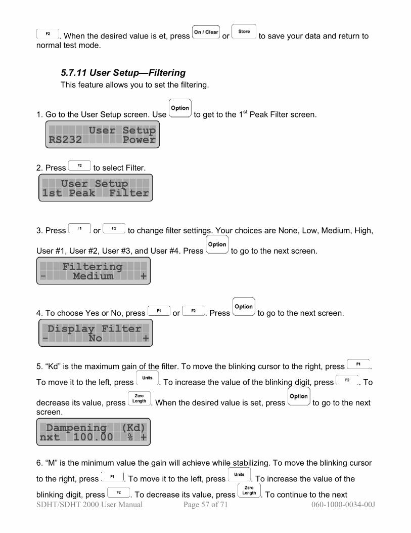
5.7.11 User Setup—Filtering This feature allows you to set the filtering.
1. Go to the User Setup screen. Use to get to the 1st Peak Filter screen.
2. Press to select Filter.
3. Press or to change filter settings. Your choices are None, Low, Medium, High,
User #1, User #2, User #3, and User #4. Press to go to the next screen.
4. To choose Yes or No, press or . Press to go to the next screen.
5. “Kd” is the maximum gain of the filter. To move the blinking cursor to the right, press .
To move it to the left, press . To increase the value of the blinking digit, press . To
decrease its value, press . When the desired value is set, press to go to the next screen.
6. “M” is the minimum value the gain will achieve while stabilizing. To move the blinking cursor
to the right, press . To move it to the left, press . To increase the value of the
blinking digit, press . To decrease its value, press . To continue to the next
SDHT/SDHT 2000 User Manual Page 58 of 71 060-1000-0034-00J
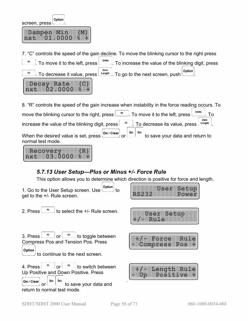
screen, press .
7. “C” controls the speed of the gain decline. To move the blinking cursor to the right press
. To move it to the left, press . To increase the value of the blinking digit, press
. To decrease it value, press . To go to the next screen, push .
8. “R” controls the speed of the gain increase when instability in the force reading occurs. To
move the blinking cursor to the right, press . To move it to the left, press . To
increase the value of the blinking digit, press . To decrease its value, press .
When the desired value is set, press or to save your data and return to normal test mode.
5.7.13 User Setup—Plus or Minus +/- Force Rule This option allows you to determine which direction is positive for force and length.
1. Go to the User Setup screen. Use to get to the +/- Rule screen.
2. Press to select the +/- Rule screen.
3. Press or to toggle between Compress Pos and Tension Pos. Press
to continue to the next screen.
4. Press or to switch between Up Positive and Down Positive. Press
or to save your data and return to normal test mode.
.

SDHT/SDHT 2000 User Manual Page 59 of 71 060-1000-0034-00J
5.8 Diagnostics The Diagnostics menu accesses a variety of tester performance functions that may help
you troubleshoot problems. Press to enter the Options Menu. Keep pressing
to cycle through all of the available options until you see .
Press to select Diagnostic. Press
again to cycle through all available options, listed at right. To scroll backward
through the menu, press . Press
to leave the Diagnostics menu and return to the regular test mode. The following sections contain detailed descriptions of the menu items.

SDHT/SDHT 2000 User Manual Page 60 of 71 060-1000-0034-00J
5.8.1 Diagnostics—Battery Voltage Use this view to check battery voltage. This information can tell you if the battery is charged. A fully charged battery should read between 6.8 and 7.2 volts. A battery connected to a charger should read 7.8 volts or higher.
1. At the Diagnostic screen, press to choose the View Battery screen.
2. To toggle between Yes and No, press or .
3. To view voltage now, press . The Voltage Mode screen will come up, followed by the Press Clear screen and a reading that tells you how much voltage the battery is supplying at the moment.
5.8.2 Diagnostics—Keypad Check Use this option to test the button layout and responsiveness of the SDHT.
1. At the Diagnostic screen, press to get to the Diagnostic options. Press to choose the Perform Keypad Check screen.
2. Press . You will see this screen, followed by another:

SDHT/SDHT 2000 User Manual Page 61 of 71 060-1000-0034-00J
3. You can now press any button on the SDHT, and the display will update. For example, by
pressing the button, the SDHT will briefly display:
Press to return to the Diagnostics menu. The SDHT will briefly display:
5.8.3 Diagnostics—Screen Check This option displays a self-advancing cursor that moves across the screen. If any inconsistencies are present on the display, they will show up in this test.
1. Scroll through the Options menu until you see the Diagnostic screen. Press to get to
the Diagnostic options. Press to choose the Perform Screen Check display.
2. Press . The Press Clear to Exit Screen Check screen will come up, then a single dark cursor will automatically advance clockwise around the display. You will hear an audible beep with each advance of the cursor.
3. When the cursor returns to the upper left corner, the entire display inverts:
4 Press to return to the normal test mode.
SDHT/SDHT 2000 User Manual Page 62 of 71 060-1000-0034-00J
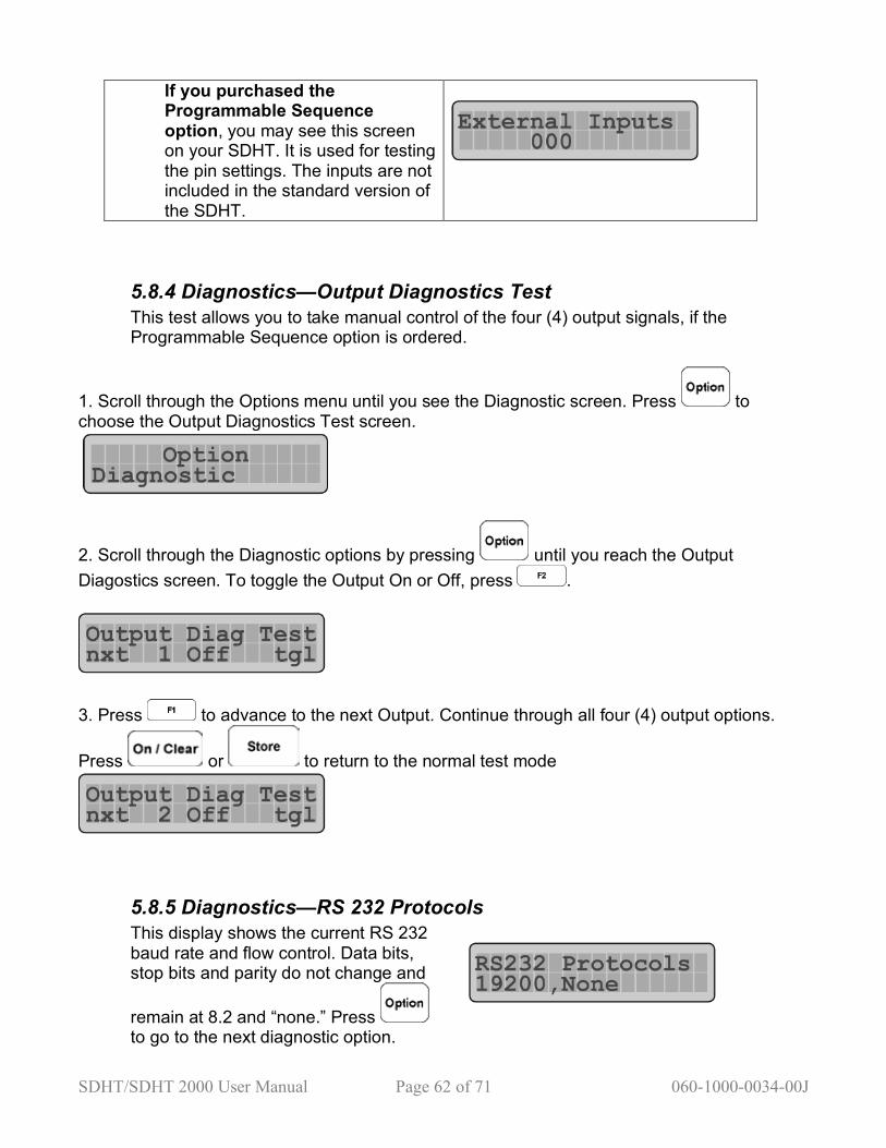
If you purchased the Programmable Sequence option, you may see this screen on your SDHT. It is used for testing the pin settings. The inputs are not included in the standard version of the SDHT.
5.8.4 Diagnostics—Output Diagnostics Test This test allows you to take manual control of the four (4) output signals, if the Programmable Sequence option is ordered.
1. Scroll through the Options menu until you see the Diagnostic screen. Press to choose the Output Diagnostics Test screen.
2. Scroll through the Diagnostic options by pressing until you reach the Output Diagostics screen. To toggle the Output On or Off, press .
3. Press to advance to the next Output. Continue through all four (4) output options.
Press or to return to the normal test mode
5.8.5 Diagnostics—RS 232 Protocols This display shows the current RS 232 baud rate and flow control. Data bits, stop bits and parity do not change and
remain at 8.2 and “none.” Press to go to the next diagnostic option.
SDHT/SDHT 2000 User Manual Page 63 of 71 060-1000-0034-00J
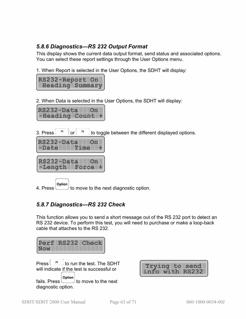
5.8.6 Diagnostics—RS 232 Output Format This display shows the current data output format, send status and associated options. You can select these report settings through the User Options menu. 1. When Report is selected in the User Options, the SDHT will display:
2. When Data is selected in the User Options, the SDHT will display:
3. Press or to toggle between the different displayed options.
4. Press to move to the next diagnostic option.
5.8.7 Diagnostics—RS 232 Check This function allows you to send a short message out of the RS 232 port to detect an RS 232 device. To perform this test, you will need to purchase or make a loop-back cable that attaches to the RS 232.
Press to run the test. The SDHT will indicate if the test is successful or
fails. Press to move to the next diagnostic option.
SDHT/SDHT 2000 User Manual Page 64 of 71 060-1000-0034-00J
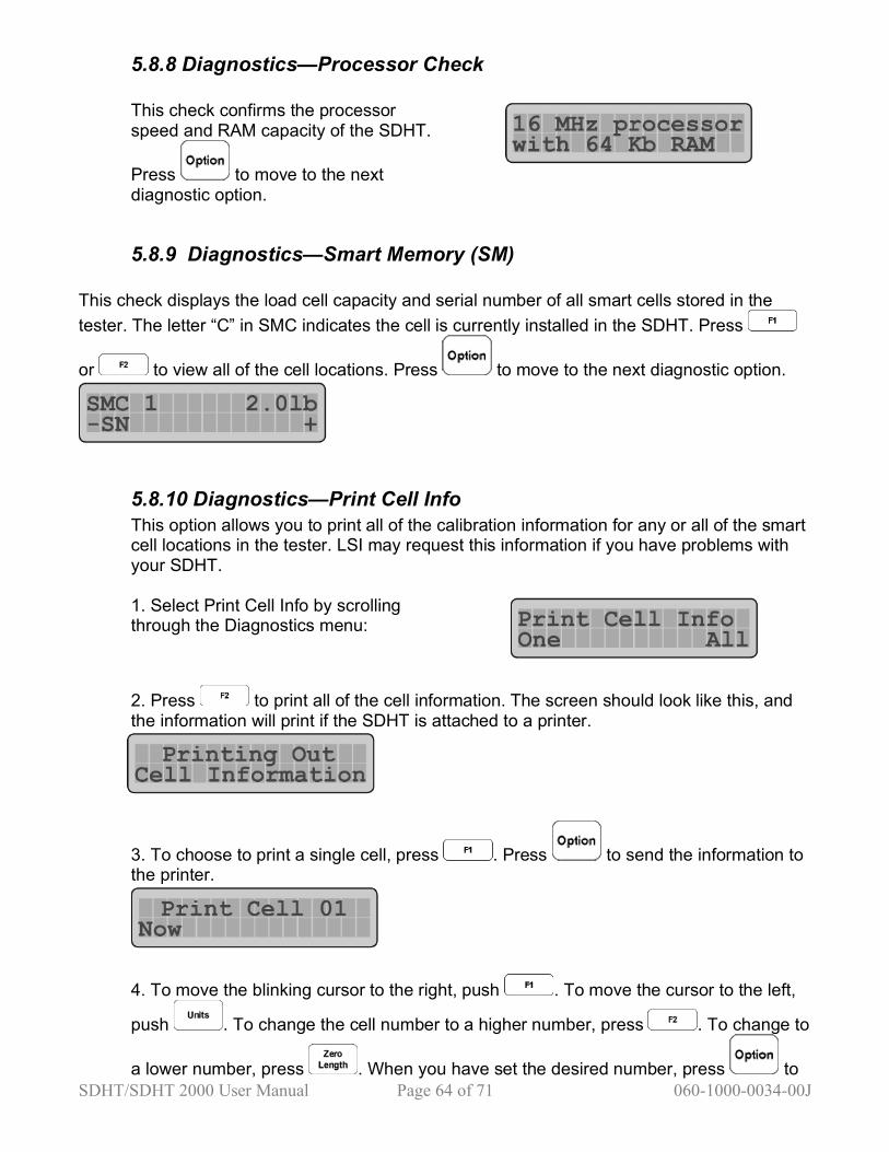
5.8.8 Diagnostics—Processor Check This check confirms the processor speed and RAM capacity of the SDHT.
Press to move to the next diagnostic option.
5.8.9 Diagnostics—Smart Memory (SM)
This check displays the load cell capacity and serial number of all smart cells stored in the tester. The letter “C” in SMC indicates the cell is currently installed in the SDHT. Press
or to view all of the cell locations. Press to move to the next diagnostic option.
5.8.10 Diagnostics—Print Cell Info This option allows you to print all of the calibration information for any or all of the smart cell locations in the tester. LSI may request this information if you have problems with your SDHT. 1. Select Print Cell Info by scrolling through the Diagnostics menu:
2. Press to print all of the cell information. The screen should look like this, and the information will print if the SDHT is attached to a printer.
3. To choose to print a single cell, press . Press to send the information to the printer.
4. To move the blinking cursor to the right, push . To move the cursor to the left,
push . To change the cell number to a higher number, press . To change to
a lower number, press . When you have set the desired number, press to

SDHT/SDHT 2000 User Manual Page 65 of 71 060-1000-0034-00J
print. Press to continue to the next diagnostic option.
5.8.11 Diagnostics—Print All Info This option allows you to print out all tester settings and information. LSI may request this information if you have trouble with your SDHT. Press to select Now.
If a printer is attached to the SDHT, the information will print and the display will return
to the previous screen. Press , or to return to normal testing mode.
5.9 Calibration Menus
There are no user-selectable options in this area. Only authorized calibration personnel who have a pass code can perform calibration. Any calibration modifications done by unauthorized personnel will void the warranty.
5.10 Factory Setup
There are no user-selectable options in this area. Only authorized LSI personnel who have a password may work in this area. Any factory setup modifications done by unauthorized personnel will void the warranty.
SDHT/SDHT 2000 User Manual Page 66 of 71 060-1000-0034-00J
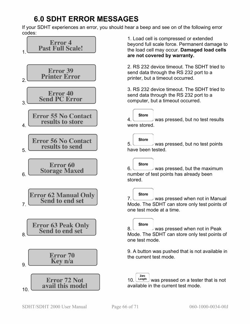
6.0 SDHT ERROR MESSAGES If your SDHT experiences an error, you should hear a beep and see on of the following error codes:
1.
1. Load cell is compressed or extended beyond full scale force. Permanent damage to the load cell may occur. Damaged load cells are not covered by warranty.
2.
2. RS 232 device timeout. The SDHT tried to send data through the RS 232 port to a printer, but a timeout occurred.
3.
3. RS 232 device timeout. The SDHT tried to send data through the RS 232 port to a computer, but a timeout occurred.
4. 4. was pressed, but no test results were stored.
5. 5. was pressed, but no test points have been tested.
6. 6. was pressed, but the maximum number of test points has already been stored.
7. 7. was pressed when not in Manual Mode. The SDHT can store only test points of one test mode at a time.
8. 8. was pressed when not in Peak Mode. The SDHT can store only test points of one test mode.
9.
9. A button was pushed that is not available in the current test mode.
10.
10. was pressed on a tester that is not available in the current test mode.

SDHT/SDHT 2000 User Manual Page 67 of 71 060-1000-0034-00J
11.
11. was pressed when no RS 232 devices were enabled.
12.
12. A power-up check found an error in the keypad. Contact LSI for service.
13.
13. A power-up check found an error in the Manual Mode A/D feature. Contact LSI for service.
14.
14. A power-up check found an error in the Peak Mode A/D feature. Contact LSI for service.
15.
15. was pressed during the testing
cycle, then was pressed. The current test cycle must be competed using the same unit of measure.
16.
16. was pressed during the testing
cycle, then was pressed. The current test cycle must be completed using the same unit of measure.
17.
17. A connected computer asked for stored test data from a tester that has no stored data.
18.
18. In the User Setup option, a display sleep time of less than 1 minute was entered. This setting must be at least 1 minute.
19.
19. A power-up check found an error in the E2 prom memory. Press , then contact LSI.
20.
20. A power-up check found an error in the RAM memory on Chip 2. Press any button to continue. This error will also produce a 2-second beep just after the initial power-on beep. Contact LSI for service.

SDHT/SDHT 2000 User Manual Page 68 of 71 060-1000-0034-00J
21.
21. The internal battery is almost discharged and needs to be recharged.
22.
22. The internal battery has become almost completely discharged and needs to recharge. The tester powers off to charge.

SDHT/SDHT 2000 User Manual Page 69 of 71 060-1000-0034-00J
7.0 TESTER DEFAULTS The SDHT is equipped with defaults set at the factory. You may wish to refer to the following if you need to change certain settings. Note: Some settings (such as calibration) are customized for each tester and therefore have no default setting. Options > User Setup > RS232 >Report: Print Report: No Print Out Format: Full Stats Printer Format: Print Heading Print Summary Printer ch, width: 80, double Printer Protocol: Hardware Printer BaudRate: 9600 Paper Type: Plain Paper Lines per page: 066 Dbl Wdth On/Off: Oki- 1F/1E Measurement Units: lb, in Length Offset: 000.0 Filtering: Medium Peak Dampening: High Backlight Timeout: 00:01:00 Power Timeout: 00:20:00 Company: Your Company Name City: Anytown, USA
8.0 TESTER MAINTENANCE Routine maintenance is limited to periodic cleaning. Apply oil to the rack and any other non-printed surfaces to prevent rust, minimize wear and to maintain smooth motion. Side clearance of the upper rack is user-adjustable and should be adjusted periodically to maintain smooth motion. The tester should be calibrated annually, and the frequency of verification should be set based on the application. For optimal performance, we recommend calibration by an LSI technician.

SDHT/SDHT 2000 User Manual Page 70 of 71 060-1000-0034-00J
Title Title to the described equipment shall remain in the seller until full, actual payment therefore shall have been made. In the event of a default, the seller shall have the right to repossess the said equipment and whatever monies shall have been paid on account shall be deemed to have been rental for the use thereof to the date of such repossession. The seller shall also have the right to hold the purchaser liable for a sum equivalent to the unpaid balance of the purchase price together with all expenses and damages that the seller may have sustained, the purchaser to receive credit however, for the net monies realized on the sale of the equipment. At the election of the seller, the seller may deem title to have passed to the purchaser, in which event the seller need not repossess the equipment, but may sue at law for the balance unpaid thereon.
Warranty The LSI Spring Testing Systems parts and labor are warranted against defects in material and workmanship to the consumer for a period of twelve months from the date of purchase. This warranty covers all parts, except consumable items. It applies only to machines and accessories which have been installed and operated in accordance with instructions in our reference manuals, have not been tampered with in any way, misused, suffered damage through accident, neglect or conditions beyond our control and have been serviced only by authorized personnel. Larson Systems Incorporated is not responsible for loss in operating performance due to environmental conditions, such as humidity, dust, corrosive chemicals, deposition of oil or other foreign matter, spillage or other conditions beyond our control. There are no other warranties expressed or implied, and Larson Systems Incorporated shall not be liable under any circumstances for incidental or consequential damage. Warranty service is conducted at LSI’s facilities in Minneapolis, MN. Return the tester freight prepaid during the warranty period, and Larson Systems Incorporated will make a warranty determination, repair and return the tester freight collect. Shipments sent collect will be rejected.

SDHT/SDHT 2000 User Manual Page 71 of 71 060-1000-0034-00J
Larson Systems Inc. 10073 Baltimore Street NE Minneapolis, MN 55449-‐4425 763-‐780-‐2131 Fax: 763-‐780-‐2182 1-‐877-‐780-‐2131 www.larsonsystems.com [email protected]