Embed Size (px)
Citation preview

V1.00.000 2017-09-27
LAUNCH CReader 5001/6001 English User’s Manual
I
Trademark Information LAUNCH is a registered trademark of LAUNCH TECH CO., LTD. (LAUNCH) in China and other countries. All other LAUNCH trademarks, service marks, domain names, logos and company names referred to in this manual are either trademarks, registered trademarks, service marks, domain names, logos and company names of or are otherwise the property of LAUNCH or its affiliates. In countries where any of the LAUNCH trademarks, service marks, domain names, logos and company names are not registered, LAUNCH claims other rights associated with unregistered trademarks, service marks, domain names, logos and company names. Other products or company names referred to in this manual may be trademarks of their respective owners. You may not use any trademark, service mark, domain name, logo, or company name of LAUNCH or any third party without permission from the owner of the applicable trademark, service mark, domain name, logo, or company name. You may contact LAUNCH at www.cnlaunch.com, or write to LAUNCH TECH. CO., LTD., Launch Industrial Park, North of Wuhe Rd., Banxuegang, Longgang, Shenzhen, Guangdong, P.R. China, to request written permission to use Materials on this manual for purposes or for all other questions relating to this manual.
Copyright Information Copyright © 2017 by LAUNCH TECH. CO., LTD. All rights reserved. No part of this publication may be reproduced, stored in a retrieval system, or transmitted in any form or by any means, electronic, mechanical, photocopying and recording or otherwise, without the prior written permission of LAUNCH. The information contained herein is designed only for the use of this unit. LAUNCH is not responsible for any use of this information as applied to other units.
General Notice Other product names used herein are for identification purposes only and may be
trademarks of their respective owners. LAUNCH disclaims any and all rights in those marks.
There is a possibility that this unit is inapplicable to some of the vehicle models or systems listed in the diagnosis section due to different countries, areas, and/or years. Do not hesitate to contact LAUNCH if you come across such questions. We are to help you solve the problem as soon as possible.
Disclaimer To take full advantage of the unit, you should be familiar with the engine. All information, illustrations, and specifications contained in this manual are based on the
latest information available at the time of publication. The right is reserved to make change at any time without notice.
Neither LAUNCH nor its affiliates shall be liable to the purchaser of this unit or third parties for damages, losses, costs or expenses incurred by purchaser or third parties as a result of: accident, misuse, or abuse of this unit, or unauthorized modifications, repairs, or alterations to this unit, or failure to strictly comply with LAUNCH operating and
LAUNCH CReader 5001/6001 English User’s Manual
II
maintenance instructions. LAUNCH shall not be liable for any damages or problems arising from the use of any
options or any consumable products other than those designated as Original LAUNCH Products or LAUNCH Approved Products by LAUNCH.
Safety Precautions and Warnings To prevent personal injury or damage to vehicles and/or the tool, please read this user’s manual first carefully and observe the following safety precautions at a minimum whenever working on a vehicle:
Always perform automotive testing in a safe environment. Do not attempt to operate or observe the tool while driving a vehicle. Operating or
observing the tool will cause driver distraction and could cause a fatal accident. Wear safety eye protection that meets ANSI standards. Keep clothing, hair, hands, tools, test equipment, etc. away from all moving or hot engine
parts. Operate the vehicle in a well-ventilated work area: Exhaust gases are poisonous. Put blocks in front of the drive wheels and never leave the vehicle unattended while
running tests. Use extreme caution when working around the ignition coil, distributor cap, ignition wires
and spark plugs. These components create hazardous voltages when the engine is running.
Put the transmission in P (for A/T) or N (for M/T) and make sure the parking brake is engaged.
Keep a fire extinguisher suitable for gasoline/chemical/electrical fires nearby. Don’t connect or disconnect any test equipment while the ignition is on or the engine is
running. Keep the tool dry, clean, free from oil/water or grease. Use a mild detergent on a clean
cloth to clean the outside of the tool, when necessary.
LAUNCH CReader 5001/6001 English User’s Manual
III
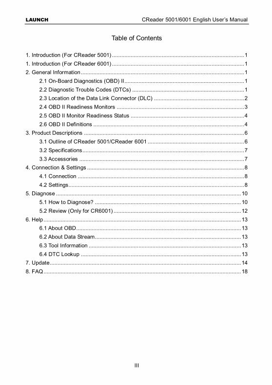
Table of Contents 1. Introduction (For CReader 5001) ..................................................................................... 1 1. Introduction (For CReader 6001) ..................................................................................... 1 2. General Information ......................................................................................................... 1
2.1 On-Board Diagnostics (OBD) II ............................................................................. 1 2.2 Diagnostic Trouble Codes (DTCs) ........................................................................ 1 2.3 Location of the Data Link Connector (DLC) .......................................................... 2 2.4 OBD II Readiness Monitors .................................................................................. 3 2.5 OBD II Monitor Readiness Status ......................................................................... 4 2.6 OBD II Definitions ................................................................................................. 4
3. Product Descriptions ....................................................................................................... 6 3.1 Outline of CReader 5001/CReader 6001 .............................................................. 6 3.2 Specifications ........................................................................................................ 7 3.3 Accessories .......................................................................................................... 7
4. Connection & Settings ..................................................................................................... 8 4.1 Connection ........................................................................................................... 8 4.2 Settings................................................................................................................. 8
5. Diagnose ....................................................................................................................... 10 5.1 How to Diagnose? .............................................................................................. 10 5.2 Review (Only for CR6001) .................................................................................. 12
6. Help ............................................................................................................................... 13 6.1 About OBD .......................................................................................................... 13 6.2 About Data Stream .............................................................................................. 13 6.3 Tool Information .................................................................................................. 13 6.4 DTC Lookup ....................................................................................................... 13
7. Update ........................................................................................................................... 14 8. FAQ ............................................................................................................................... 18

LAUNCH CReader 5001/6001 English User’s Manual
1
1. Introduction (For CReader 5001) Featuring the 2.8” color LCD, CReader 5001 delivers leading OBDII/EOBD diagnostic functions and meets protocols such as ISO9141-2, ISO14230-4, SAEJ1850 and ISO15765-4 etc.
It can be connected to PC through the USB cable for upgrade to keep synchronized with the latest software version.
Note: CReader 5001 may automatically reset while being disturbed by strong static electricity. THIS IS A NORMAL REACTION.
1. Introduction (For CReader 6001) Featuring the 2.8” color LCD, CReader 6001 delivers full OBDII/EOBD diagnostic functions and meets protocols such as ISO9141-2, ISO14230-4, SAEJ1850 and ISO15765-4 etc. Moreover, it also supports data stream recording and playback.
It can be connected to PC through the USB cable for upgrade to keep synchronized with the latest software version.
Note: CReader 6001 may automatically reset while being disturbed by strong static electricity. THIS IS A NORMAL REACTION.
2. General Information 2.1 On-Board Diagnostics (OBD) II
The first generation of On-Board Diagnostics (OBD I) was developed by the California Air Resources Board (ARB) and implemented in 1988 to monitor some of the emission control components on vehicles. As technology evolved and the desire to improve the On-Board Diagnostic system increased, a new generation of On-Board Diagnostic system was developed. This second generation of On-Board Diagnostic regulations is called “OBD II”.
The OBD II system is designed to monitor emission control systems and key engine components by performing either continuous or periodic tests of specific components and vehicle conditions. When a problem is detected, the OBD II system turns on a warning lamp (MIL) on the vehicle instrument panel to alert the driver typically by the phrase of “Check Engine” or “Service Engine Soon”. The system will also store important information about the detected malfunction so that a technician can accurately find and fix the problem. Here below follow three pieces of such valuable information:
1) Whether the Malfunction Indicator Light (MIL) is commanded ‘on’ or ‘off’; 2) Which, if any, Diagnostic Trouble Codes (DTCs) are stored; 3) Readiness Monitor status.
2.2 Diagnostic Trouble Codes (DTCs)
OBD II Diagnostic Trouble Codes are codes that are stored by the on-board computer
LAUNCH CReader 5001/6001 English User’s Manual
2
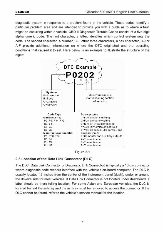
diagnostic system in response to a problem found in the vehicle. These codes identify a particular problem area and are intended to provide you with a guide as to where a fault might be occurring within a vehicle. OBD II Diagnostic Trouble Codes consist of a five-digit alphanumeric code. The first character, a letter, identifies which control system sets the code. The second character, a number, 0-3; other three characters, a hex character, 0-9 or A-F provide additional information on where the DTC originated and the operating conditions that caused it to set. Here below is an example to illustrate the structure of the digits:
Figure 2-1
2.3 Location of the Data Link Connector (DLC)
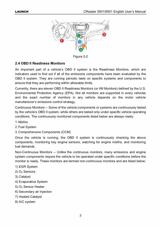
The DLC (Data Link Connector or Diagnostic Link Connector) is typically a 16-pin connector where diagnostic code readers interface with the vehicle’s on-board computer. The DLC is usually located 12 inches from the center of the instrument panel (dash), under or around the driver’s side for most vehicles. If Data Link Connector is not located under dashboard, a label should be there telling location. For some Asian and European vehicles, the DLC is located behind the ashtray and the ashtray must be removed to access the connector. If the DLC cannot be found, refer to the vehicle’s service manual for the location.
LAUNCH CReader 5001/6001 English User’s Manual
3
Figure 2-2
2.4 OBD II Readiness Monitors
An important part of a vehicle’s OBD II system is the Readiness Monitors, which are indicators used to find out if all of the emissions components have been evaluated by the OBD II system. They are running periodic tests on specific systems and components to ensure that they are performing within allowable limits.
Currently, there are eleven OBD II Readiness Monitors (or I/M Monitors) defined by the U.S. Environmental Protection Agency (EPA). Not all monitors are supported in every vehicles and the exact number of monitors in any vehicle depends on the motor vehicle manufacturer’s emissions control strategy.
Continuous Monitors -- Some of the vehicle components or systems are continuously tested by the vehicle’s OBD II system, while others are tested only under specific vehicle operating conditions. The continuously monitored components listed below are always ready:
1. Misfire 2. Fuel System 3. Comprehensive Components (CCM)
Once the vehicle is running, the OBD II system is continuously checking the above components, monitoring key engine sensors, watching for engine misfire, and monitoring fuel demands.
Non-Continuous Monitors -- Unlike the continuous monitors, many emissions and engine system components require the vehicle to be operated under specific conditions before the monitor is ready. These monitors are termed non-continuous monitors and are listed below:
1) EGR System 2) O2 Sensors 3) Catalyst 4) Evaporative System 5) O2 Sensor Heater 6) Secondary air Injection 7) Heated Catalyst 8) A/C system
LAUNCH CReader 5001/6001 English User’s Manual
4
2.5 OBD II Monitor Readiness Status
OBD II systems must indicate whether or not the vehicle’s PCM’s monitor system has completed testing on each component. Components that have been tested will be reported as “Ready”, or “Complete”, meaning they have been tested by the OBD II system. The purpose of recording readiness status is to allow inspectors to determine if the vehicle’s OBD II system has tested all the components and/or systems.
The Powertrain Control Module (PCM) sets a monitor to “Ready” or “Complete” after an appropriate drive cycle has been performed. The drive cycle that enables a monitor and sets readiness codes to “Ready” varies for each individual monitor. Once a monitor is set as “Ready” or “Complete”, it will remain in this state. A number of factors, including erasing of Diagnostic Trouble Codes (DTCs) with a code reader or a disconnected battery, can result in Readiness Monitors being set to “Not Ready”. Since the three continuous monitors are constantly evaluating, they will be reported as “Ready” all of the time. If testing of a particular supported non-continuous monitor has not been completed, the monitor status will be reported as “Not Complete” or “Not Ready.”
In order for the OBD monitor system to become ready, the vehicle should be driven under a variety of normal operating conditions. These operating conditions may include a mix of highway driving and stop and go, city type driving, and at least one overnight-off period. For specific information on getting your vehicle’s OBD monitor system ready, please consult your vehicle owner’s manual.
2.6 OBD II Definitions
Powertrain Control Module (PCM) – It is the OBD II terminology for the on-board computer that controls engine and drive train.
Malfunction Indicator Light (MIL) -- Malfunction Indicator Light (Service Engine Soon, Check Engine) is a term used for the light on the instrument panel. It is to alert the driver and/or the repair technician that there is a problem with one or more of vehicle’s systems and may cause emissions to exceed federal standards. If the MIL illuminates with a steady light, it indicates that a problem has been detected and the vehicle should be serviced as soon as possible. Under certain conditions, the dashboard light will blink or flash. This indicates a severe problem and flashing is intended to discourage vehicle operation. The vehicle onboard diagnostic system cannot turn the MIL off until the necessary repairs are completed or the condition no longer exists.
DTC -- Diagnostic Trouble Codes (DTC) that identifies which section of the emission control system has malfunctioned.
Enabling Criteria -- Also termed Enabling Conditions. They are the vehicle-specific events or conditions that must occur within the engine before the various monitors will set, or run. Some monitors require the vehicle to follow a prescribed “drive cycle” routine as part of the enabling criteria. Drive cycles vary among vehicles and for each monitor in any particular vehicle. Please refer to the vehicle’s factory service manual for specific enabling procedures.
LAUNCH CReader 5001/6001 English User’s Manual
5
OBD II Drive Cycle -- A specific mode of vehicle operation that provides conditions required to set all the readiness monitors applicable to the vehicle to the “ready” condition. The purpose of completing an OBD II drive cycle is to force the vehicle to run its onboard diagnostics. Some form of a drive cycle needs to be performed after DTCs have been erased from the PCM’s memory or after the battery has been disconnected. Running through a vehicle’s complete drive cycle will “set” the readiness monitors so that future faults can be detected. Drive cycles vary depending on the vehicle and the monitor that needs to be reset. For vehicle specific drive cycle, consult the service manual.
Freeze Frame Data -- When an emissions related fault occurs, the OBD II system not only sets a code but also records a snapshot of the vehicle operating parameters to help in identifying the problem. This set of values is referred to as Freeze Frame Data and may include important engine parameters such as engine RPM, vehicle speed, air flow, engine load, fuel pressure, fuel trim value, engine coolant temperature, ignition timing advance, or closed loop status.
Fuel Trim (FT) -- Feedback adjustments to the base fuel schedule. Short-term fuel trim refers to dynamic or instantaneous adjustments. Long-term fuel trim refers to much more gradual adjustments to the fuel calibration schedule than short-term trim adjustments. These long-term adjustments compensate for vehicle differences and gradual changes that occur over time.
LAUNCH CReader 5001/6001 English User’s Manual
6
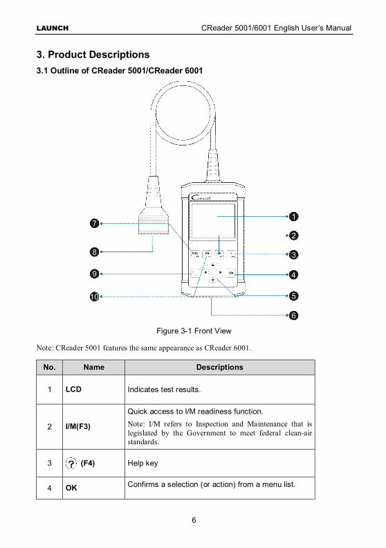
3. Product Descriptions 3.1 Outline of CReader 5001/CReader 6001
Figure 3-1 Front View
Note: CReader 5001 features the same appearance as CReader 6001.
No. Name Descriptions
1 LCD Indicates test results.
2 I/M(F3)
Quick access to I/M readiness function. Note: I/M refers to Inspection and Maintenance that is legislated by the Government to meet federal clean-air standards.
3 (F4) Help key
4 OK Confirms a selection (or action) from a menu list.
LAUNCH CReader 5001/6001 English User’s Manual
7
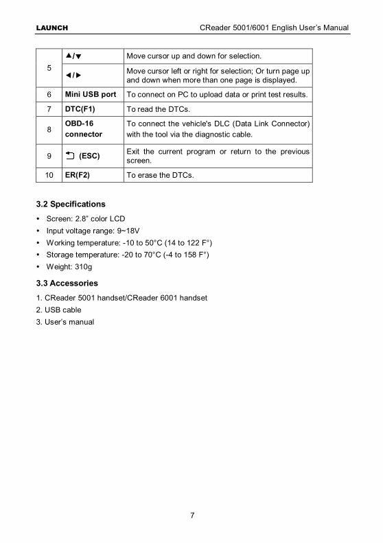
5 / Move cursor up and down for selection.
/ Move cursor left or right for selection; Or turn page up and down when more than one page is displayed.
6 Mini USB port To connect on PC to upload data or print test results.
7 DTC(F1) To read the DTCs.
8 OBD-16 connector
To connect the vehicle's DLC (Data Link Connector) with the tool via the diagnostic cable.
9 (ESC) Exit the current program or return to the previous screen.
10 ER(F2) To erase the DTCs.
3.2 Specifications
Screen: 2.8” color LCD Input voltage range: 9~18V Working temperature: -10 to 50°C (14 to 122 F°) Storage temperature: -20 to 70°C (-4 to 158 F°) Weight: 310g
3.3 Accessories
1. CReader 5001 handset/CReader 6001 handset 2. USB cable 3. User’s manual
LAUNCH CReader 5001/6001 English User’s Manual
8
4. Connection & Settings 4.1 Connection
1. Turn the ignition off.
2. Locate vehicle’s DLC socket: Refer to figure 2-2 for the location.
3. Plug the other end of the diagnostic cable into the vehicle’s DLC.
4. Turn the ignition on. Engine can be off or running.
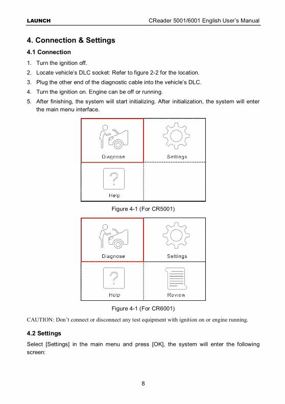
5. After finishing, the system will start initializing. After initialization, the system will enter the main menu interface.
Figure 4-1 (For CR5001)
Figure 4-1 (For CR6001)
CAUTION: Don’t connect or disconnect any test equipment with ignition on or engine running.
4.2 Settings
Select [Settings] in the main menu and press [OK], the system will enter the following screen:
LAUNCH CReader 5001/6001 English User’s Manual
9
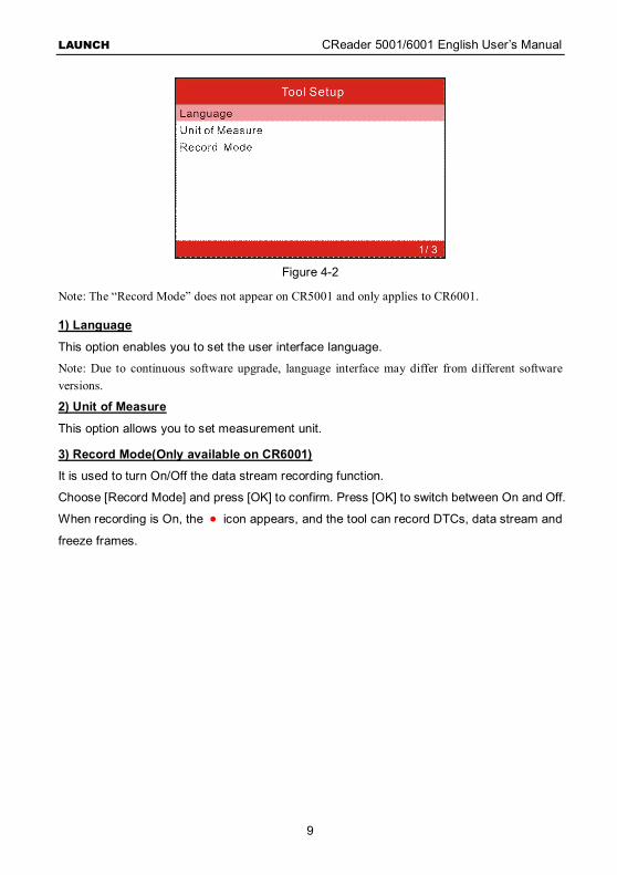
Figure 4-2
Note: The “Record Mode” does not appear on CR5001 and only applies to CR6001.
1) Language
This option enables you to set the user interface language.
Note: Due to continuous software upgrade, language interface may differ from different software versions.
2) Unit of Measure
This option allows you to set measurement unit.
3) Record Mode(Only available on CR6001)
It is used to turn On/Off the data stream recording function.
Choose [Record Mode] and press [OK] to confirm. Press [OK] to switch between On and Off.
When recording is On, the ● icon appears, and the tool can record DTCs, data stream and
freeze frames.

LAUNCH CReader 5001/6001 English User’s Manual
10
5. Diagnose 5.1 How to Diagnose?
Select [Diagnose] in Main Menu and press [OK], the screen will display Entering System interface as following figure 5-1:
Figure 5-1 In figure 5-1, after entering the system, the screen will automatically jump to figure 5-2:
Figure 5-2
Press [OK], a screen similar to figure 5-3 will appear:
LAUNCH CReader 5001/6001 English User’s Manual
11
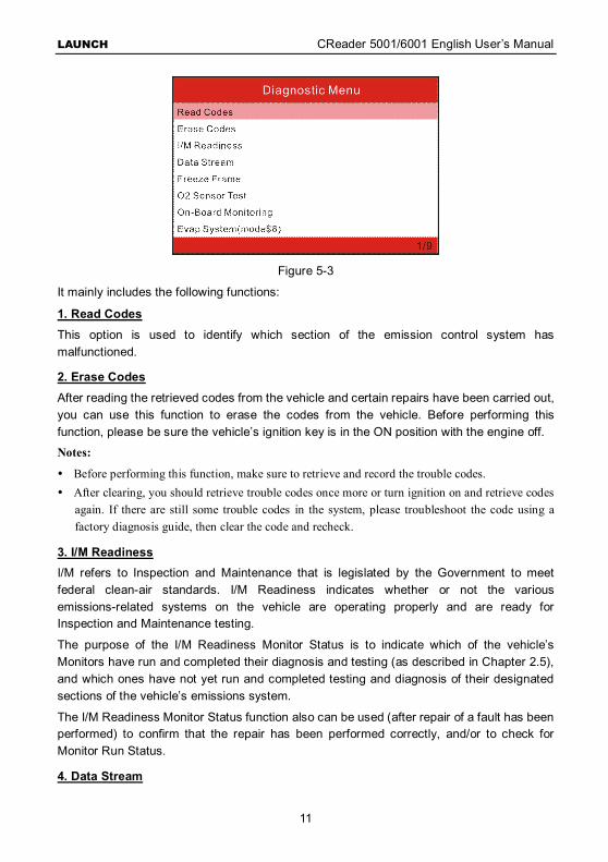
Figure 5-3
It mainly includes the following functions:
1. Read Codes This option is used to identify which section of the emission control system has malfunctioned.
2. Erase Codes After reading the retrieved codes from the vehicle and certain repairs have been carried out, you can use this function to erase the codes from the vehicle. Before performing this function, please be sure the vehicle’s ignition key is in the ON position with the engine off.
Notes:
Before performing this function, make sure to retrieve and record the trouble codes. After clearing, you should retrieve trouble codes once more or turn ignition on and retrieve codes
again. If there are still some trouble codes in the system, please troubleshoot the code using a factory diagnosis guide, then clear the code and recheck.
3. I/M Readiness I/M refers to Inspection and Maintenance that is legislated by the Government to meet federal clean-air standards. I/M Readiness indicates whether or not the various emissions-related systems on the vehicle are operating properly and are ready for Inspection and Maintenance testing.
The purpose of the I/M Readiness Monitor Status is to indicate which of the vehicle’s Monitors have run and completed their diagnosis and testing (as described in Chapter 2.5), and which ones have not yet run and completed testing and diagnosis of their designated sections of the vehicle’s emissions system.
The I/M Readiness Monitor Status function also can be used (after repair of a fault has been performed) to confirm that the repair has been performed correctly, and/or to check for Monitor Run Status.
4. Data Stream
LAUNCH CReader 5001/6001 English User’s Manual
12
This option retrieves and displays live data and parameters from the vehicle’s ECU.
5. View Freeze Frame When an emission-related fault occurs, certain vehicle conditions are recorded by the on-board computer. This information is referred to as freeze frame data. Freeze Data is a snapshot of the operating conditions at the time of an emission-related fault.
Note: if DTCs were erased, Freeze Data may not be stored in vehicle memory depending on vehicle.
6. O2 Sensor Test This option allows retrieval and viewing of O2 sensor test results for most recently performed tests from the vehicle’s on-board computer.
7. On-board Monitoring This function can be utilized to read the results of on-board diagnostic monitoring tests for specific components/systems.
8. EVAP System The EVAP test function lets you initiate a leak test for the vehicle’s EVAP system. Before using the system test function, refer to the vehicle’s service repair manual to determine the procedures necessary to stop the test.
9. Vehicle Information The option displays the Vehicle Identification Number (VIN), the Calibration Verification Number (CVN), and other information of the test vehicle.
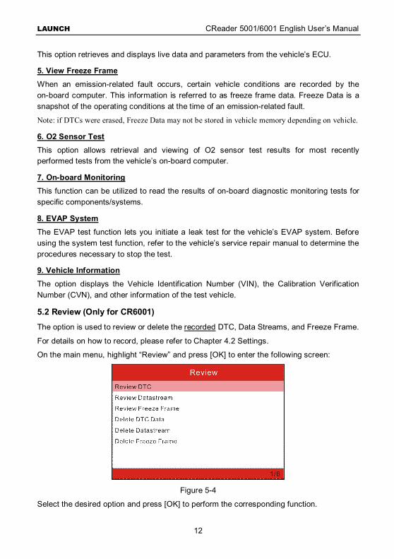
5.2 Review (Only for CR6001)
The option is used to review or delete the recorded DTC, Data Streams, and Freeze Frame.
For details on how to record, please refer to Chapter 4.2 Settings.
On the main menu, highlight “Review” and press [OK] to enter the following screen:
Figure 5-4
Select the desired option and press [OK] to perform the corresponding function.
LAUNCH CReader 5001/6001 English User’s Manual
13
6. Help This menu enables you to view the tool information and retrieve the vehicle’s DLC. In the main menu, select [Help] and press [OK] to enter figure 6-1.
Figure 6-1
6.1 About OBD
This option allows you to have a general knowledge of OBD.
6.2 About Data Stream
This option displays the related introductions about Data Stream.
6.3 Tool Information
This option displays the related information of your tool.
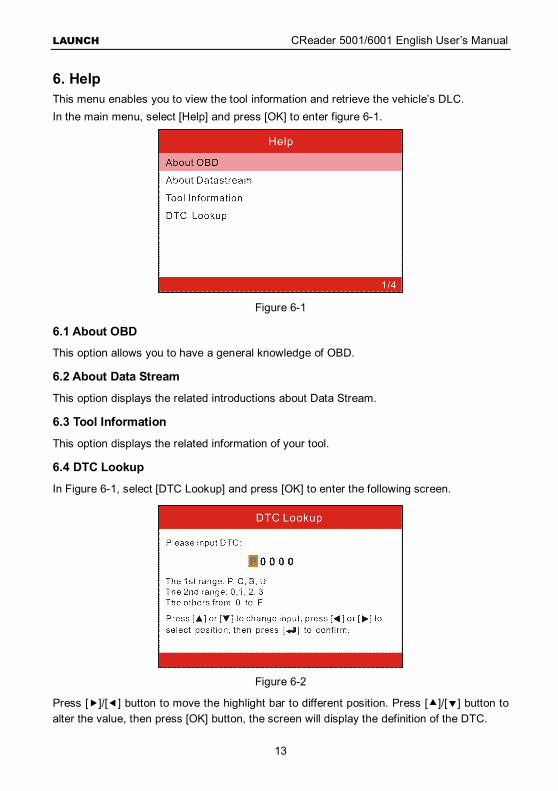
6.4 DTC Lookup
In Figure 6-1, select [DTC Lookup] and press [OK] to enter the following screen.
Figure 6-2
Press []/[] button to move the highlight bar to different position. Press []/[] button to alter the value, then press [OK] button, the screen will display the definition of the DTC.
LAUNCH CReader 5001/6001 English User’s Manual
14
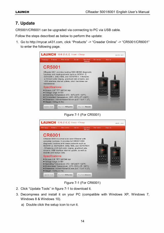
7. Update CR5001/CR6001 can be upgraded via connecting to PC via USB cable.
Follow the steps described as below to perform the update:
1. Go to http://mycar.x431.com, click “Products” -> “Creader Online” -> “CR5001/CR6001” to enter the following page.
Figure 7-1 (For CR5001)
Figure 7-1 (For CR6001)
2. Click “Update Tools” in figure 7-1 to download it.
3. Decompress and install it on your PC (compatible with Windows XP, Windows 7, Windows 8 & Windows 10).
a) Double click the setup icon to run it.
LAUNCH CReader 5001/6001 English User’s Manual
15
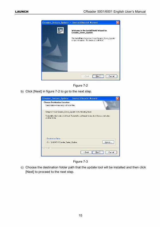
Figure 7-2
b) Click [Next] in figure 7-2 to go to the next step.
Figure 7-3
c) Choose the destination folder path that the update tool will be installed and then click [Next] to proceed to the next step.
LAUNCH CReader 5001/6001 English User’s Manual
16
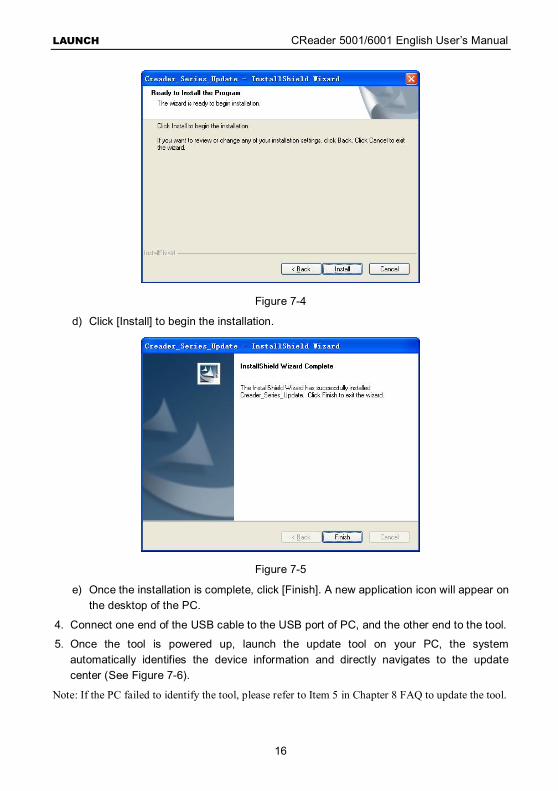
Figure 7-4
d) Click [Install] to begin the installation.
Figure 7-5
e) Once the installation is complete, click [Finish]. A new application icon will appear on the desktop of the PC.
4. Connect one end of the USB cable to the USB port of PC, and the other end to the tool.
5. Once the tool is powered up, launch the update tool on your PC, the system automatically identifies the device information and directly navigates to the update center (See Figure 7-6).
Note: If the PC failed to identify the tool, please refer to Item 5 in Chapter 8 FAQ to update the tool.
LAUNCH CReader 5001/6001 English User’s Manual
17
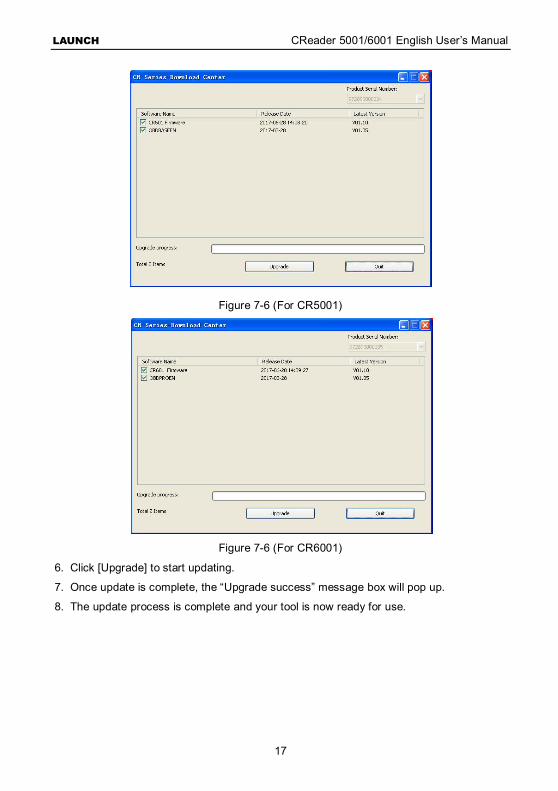
Figure 7-6 (For CR5001)
Figure 7-6 (For CR6001)
6. Click [Upgrade] to start updating.
7. Once update is complete, the “Upgrade success” message box will pop up.
8. The update process is complete and your tool is now ready for use.
LAUNCH CReader 5001/6001 English User’s Manual
18
8. FAQ Here we list some frequently asked questions and answers related to the tool.
1. Question: System halts when reading data stream. What is the reason?
Answer: It may be caused by a slackened connector. Please turn off the tool, firmly connect the connector, and switch it on again.
2. Question: Screen of main unit flashes at engine ignition start.
Answer: Caused by electromagnetic disturbing, and this is normal phenomenon.
3. Question: There is no response when communicating with on-board computer.
Answer: Please confirm the proper voltage of power supply and check if the throttle has been closed, the transmission is in the neutral position, and the water is in proper temperature.
4. Question: Why are there so many fault codes?
Answer: Usually, it’s caused by poor connection or fault circuit grounding.
5. Question: How to do if the PC failed to identify the tool while upgrading the tool?
Answer: Generally, it mainly results from the incorrect installation of the update tool driver. Double check the installation status of the USB driver by clicking “My Computer” -> “Properties” -> “Device Manager” -> “Universal Serial Bus controllers”. If installation failure occurs, a failure icon will appear before the device name. In this case, re-install it.
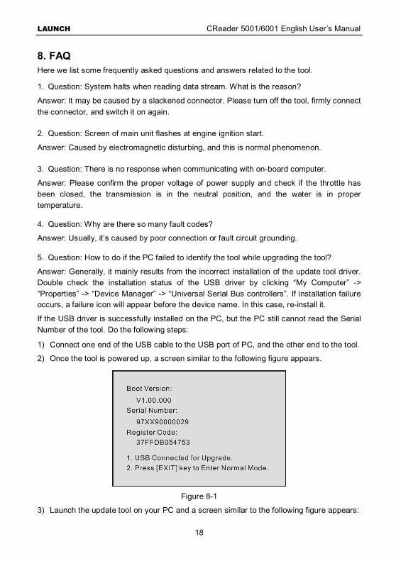
If the USB driver is successfully installed on the PC, but the PC still cannot read the Serial Number of the tool. Do the following steps:
1) Connect one end of the USB cable to the USB port of PC, and the other end to the tool.
2) Once the tool is powered up, a screen similar to the following figure appears.
Figure 8-1
3) Launch the update tool on your PC and a screen similar to the following figure appears:
LAUNCH CReader 5001/6001 English User’s Manual
19
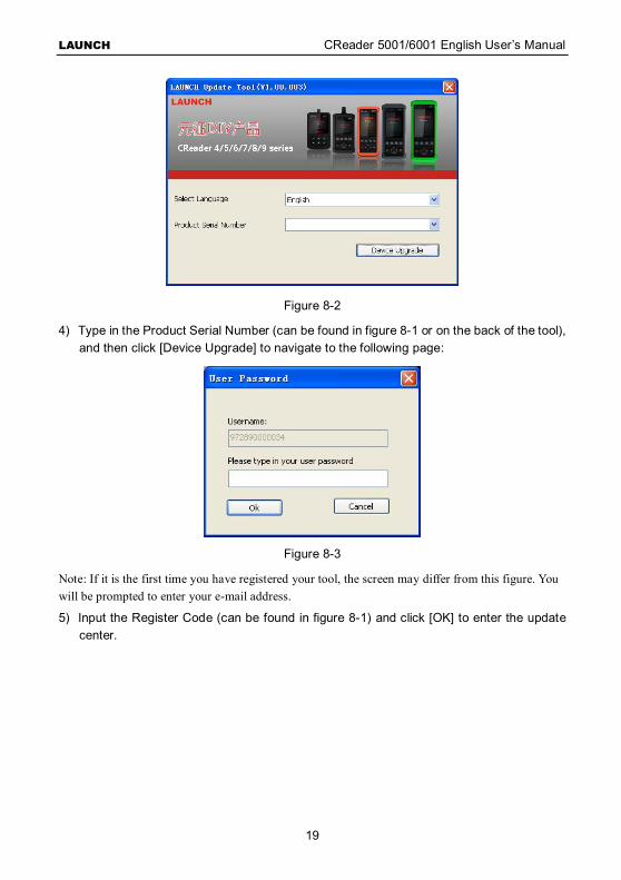
Figure 8-2
4) Type in the Product Serial Number (can be found in figure 8-1 or on the back of the tool), and then click [Device Upgrade] to navigate to the following page:
Figure 8-3
Note: If it is the first time you have registered your tool, the screen may differ from this figure. You will be prompted to enter your e-mail address.
5) Input the Register Code (can be found in figure 8-1) and click [OK] to enter the update center.
LAUNCH CReader 5001/6001 English User’s Manual
20
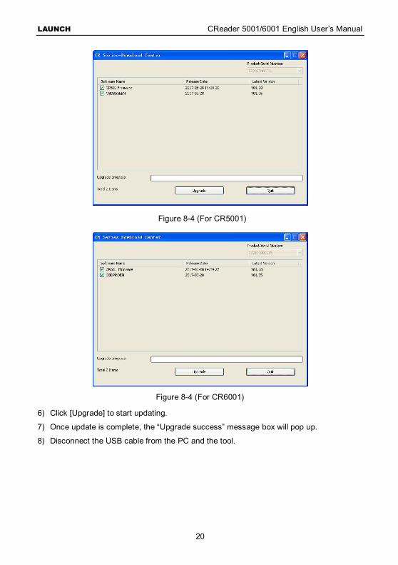
Figure 8-4 (For CR5001)
Figure 8-4 (For CR6001)
6) Click [Upgrade] to start updating.
7) Once update is complete, the “Upgrade success” message box will pop up.
8) Disconnect the USB cable from the PC and the tool.
LAUNCH CReader 5001/6001 English User’s Manual
21
Warranty
THIS WARRANTY IS EXPRESSLY LIMITED TO PERSONS WHO PURCHASE LAUNCH PRODUCTS FOR PURPOSES OF RESALE OR USE IN THE ORDINARY COURSE OF THE BUYER’S BUSINESS. LAUNCH electronic product is warranted against defects in materials and workmanship for one year (12 months) from date of delivery to the user. This warranty does not cover any part that has been abused, altered, used for a purpose other than for which it was intended, or used in a manner inconsistent with instructions regarding use. The exclusive remedy for any automotive meter found to be defective is repair or replacement, and LAUNCH shall not be liable for any consequential or incidental damages. Final determination of defects shall be made by LAUNCH in accordance with procedures established by LAUNCH. No agent, employee, or representative of LAUNCH has any authority to bind LAUNCH to any affirmation, representation, or warranty concerning LAUNCH automotive meters, except as stated herein.
Order Information Replaceable and optional parts can be ordered directly from your LAUNCH authorized tool supplier. Your order should include the following information: Quantity Part number Item description
Customer Service If you have any questions on the operation of the unit, please contact local dealer, or contact LAUNCH TECH. CO., LTD: Tel: 86-755-84528767 E-mail: [email protected]

LAUNCH CReader 5001/6001 English User’s Manual
22
Statement:
LAUNCH reserves the rights to make any change to product designs and specifications without notice. The actual object may differ a little from the descriptions in the manual in physical appearance, color and configuration. We have tried our best to make the descriptions and illustrations in the manual as accurate as possible, and defects are inevitable. If you have any question, please contact local dealer or after-sale service center of LAUNCH. LAUNCH does not bear any responsibility arising from misunderstandings.