Embed Size (px)
Citation preview
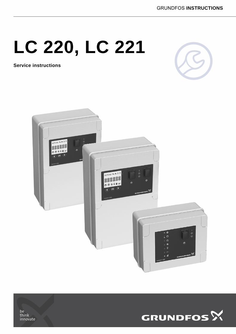
LC 220, LC 221Service instructions
GRUNDFOS INSTRUCTIONS

En
glis
h (G
B)
English (GB) Service instructions
Original service instructions.
CONTENTSPage
1. Symbols used in this document
2. Safety
Sumps and pits for submersible wastewater pumps may contain gasses and wastewater with toxic and/or disease-causing substances. Therefore, all persons involved must wear appropriate personal protective equipment and clothing, and all work on and near the pump must be carried out under strict observance of hygienic regulations.
1. Symbols used in this document 2
2. Safety 2
3. Identification 3
4. Maintenance 44.1 Electrical maintenance 44.2 Cleaning the pressure tube of the sensor 4
5. General service information 45.1 Please read this before replacing anything 45.2 Checking for pressure leakages 45.3 Before dismantling 45.4 Replacement 55.4.1 Complete controller (LC 220 and LC 221) 55.4.2 Main board LC 220 55.4.3 Main board LC 221 55.4.4 LC 221 replacement of display 55.4.5 Replacement of level sensor 65.5 Settings 75.5.1 Calibration of level sensor 75.6 Checks 75.6.1 Checking the level sensor 76. Fault finding 86.1 Fault finding of LC 220 86.2 Fault finding of LC 221 10
7. Wiring diagrams 12
Warning
If these safety instructions are not observed, it may result in personal injury.
Warning
If these instructions are not observed, it may lead to electric shock with consequent risk of serious personal injury or death.
Warning
These instructions must be observed for explosion-proof versions. We recommend that you also follow these instructions for standard versions.
CautionIf these safety instructions are not observed, it may result in malfunction or damage to the equipment.
NoteNotes or instructions that make the job easier and ensure safe operation.
Warning
Work in or near pits must be carried out according to local regulations.
Warning
Always lift the pump by its lifting bracket or by means of a forklift truck if the pump is on a pallet. Never lift the pump by the motor cable or the hose/pipe.
2

En
gli
sh
(G
B)
3. IdentificationNameplate, LC 220
Fig. 1 Nameplate, LC 220
Type key, LC 220
Nameplate, LC 221
Fig. 2 Nameplate, LC 221
Type key, LC 221
TM
05
13
51
33
11
Pos. Description
1 Type designation
2 Product number
3 Version number
4 Rated voltage
5 Power consumption
6 Maximum back-up fuse
7 Weight
8 Maximum pump input current
9 Production year and week
10 Serial number
11 Maximum voltage at contactor
12 Maximum current at contactor
Example LC 220 .1 .230 .1 .8
LC 220 = controller type
1 = one-pump controller2 = two-pump controller
Voltage [V]
1 = single-phase3 = three-phase
Maximum operating current per pump [A]
TypeProd. No.UN
Pmax
IFuse max
G
P.c.Serial No.VContact max
IContact max
TAmb.: 0 to 40 CIPump max
Ic < 10 kA IP55
LC 220.1.400.3.498167897 V01
3x 380-415V~ 50/60Hz3W 4A
16A
12268888250V
2A
1,8kgMade in Germany
1 32
4
6
5
7
9
11
10
12
8
TM
05
47
82
26
12
Pos. Description
1 Type designation
2 Product number
3 Production code (year, week)
4 Number of phases
5 Maximum pump input current
6 Maximum voltage at potential-free contact
7 Maximum back-up fuse
8 Minimum ambient temperature
9 Version
10 Serial number
11 Rated voltage
12 Power consumption
13 Maximum current at potential-free contact
14 Weight
15 Maximum ambient temperature
16 Frequency
Example LC 221 .1 .230 .1 .10 .30
LC 221 = controller type
1 = one-pump controller2 = two-pump controller
Voltage [V]
1 = single-phase3 = three-phase
Maximum operating current [A]
Capacitors [μF]
Starting method:[ ] = DOLSD = Star-delta
1
234567
8
9
10
1112
1314
15
16
Type
Prod.-No.P.c.
f
Phases U
G
Serial no.
Pmax
TAmb max
IPump max
VA
HzCOkg
9818
9707
LC 221.1.230.1.10.30/150 MPU9818970712211
10250160
V010012
220-24032
5.24050
Ucontact max
IFuse max
TAmb min
A
CO
Icontact max
VWA
Ic < 10 kAIP55
Made in Germany
3
En
glis
h (G
B)
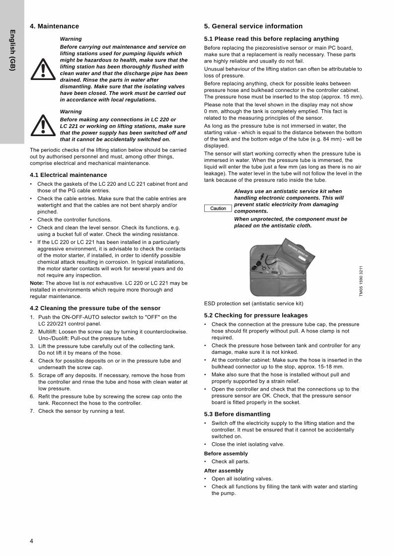
4. Maintenance
The periodic checks of the lifting station below should be carried out by authorised personnel and must, among other things, comprise electrical and mechanical maintenance.
4.1 Electrical maintenance
• Check the gaskets of the LC 220 and LC 221 cabinet front and those of the PG cable entries.
• Check the cable entries. Make sure that the cable entries are watertight and that the cables are not bent sharply and/or pinched.
• Check the controller functions.
• Check and clean the level sensor. Check its functions, e.g. using a bucket full of water. Check the winding resistance.
• If the LC 220 or LC 221 has been installed in a particularly aggressive environment, it is advisable to check the contacts of the motor starter, if installed, in order to identify possible chemical attack resulting in corrosion. In typical installations, the motor starter contacts will work for several years and do not require any inspection.
Note: The above list is not exhaustive. LC 220 or LC 221 may be installed in environments which require more thorough and regular maintenance.
4.2 Cleaning the pressure tube of the sensor
1. Push the ON-OFF-AUTO selector switch to "OFF" on the LC 220/221 control panel.
2. Multilift: Loosen the screw cap by turning it counterclockwise. Uno-/Duolift: Pull-out the pressure tube.
3. Lift the pressure tube carefully out of the collecting tank. Do not lift it by means of the hose.
4. Check for possible deposits on or in the pressure tube and underneath the screw cap.
5. Scrape off any deposits. If necessary, remove the hose from the controller and rinse the tube and hose with clean water at low pressure.
6. Refit the pressure tube by screwing the screw cap onto the tank. Reconnect the hose to the controller.
7. Check the sensor by running a test.
5. General service information
5.1 Please read this before replacing anything
Before replacing the piezoresistive sensor or main PC board, make sure that a replacement is really necessary. These parts are highly reliable and usually do not fail.
Unusual behaviour of the lifting station can often be attributable to loss of pressure.
Before replacing anything, check for possible leaks between pressure hose and bulkhead connector in the controller cabinet. The pressure hose must be inserted to the stop (approx. 15 mm).
Please note that the level shown in the display may not show0 mm, although the tank is completely emptied. This fact is related to the measuring principles of the sensor.
As long as the pressure tube is not immersed in water, the starting value - which is equal to the distance between the bottom of the tank and the bottom edge of the tube (e.g. 84 mm) - will be displayed.
The sensor will start working correctly when the pressure tube is immersed in water. When the pressure tube is immersed, the liquid will enter the tube just a few mm (as long as there is no air leakage). The water level in the tube will not follow the level in the tank because of the pressure ratio inside the tube.
ESD protection set (antistatic service kit)
5.2 Checking for pressure leakages
• Check the connection at the pressure tube cap, the pressure hose should fit properly without pull. A hose clamp is not required.
• Check the pressure hose between tank and controller for any damage, make sure it is not kinked.
• At the controller cabinet: Make sure the hose is inserted in the bulkhead connector up to the stop, approx. 15-18 mm.
• Make also sure that the hose is installed without pull and properly supported by a strain relief.
• Open the controller and check that the connections up to the pressure sensor are OK. Check, that the pressure sensor board is fitted properly in the socket.
5.3 Before dismantling
• Switch off the electricity supply to the lifting station and the controller. It must be ensured that it cannot be accidentally switched on.
• Close the inlet isolating valve.
Before assembly
• Check all parts.
After assembly
• Open all isolating valves.
• Check all functions by filling the tank with water and starting the pump.
Warning
Before carrying out maintenance and service on lifting stations used for pumping liquids which might be hazardous to health, make sure that the lifting station has been thoroughly flushed with clean water and that the discharge pipe has been drained. Rinse the parts in water after dismantling. Make sure that the isolating valves have been closed. The work must be carried out in accordance with local regulations.
Warning
Before making any connections in LC 220 orLC 221 or working on lifting stations, make sure that the power supply has been switched off and that it cannot be accidentally switched on.
Caution
Always use an antistatic service kit when handling electronic components. This will prevent static electricity from damaging components.
When unprotected, the component must be placed on the antistatic cloth.
TM
05
15
90
32
11
4
En
gli
sh
(G
B)
5.4 Replacement
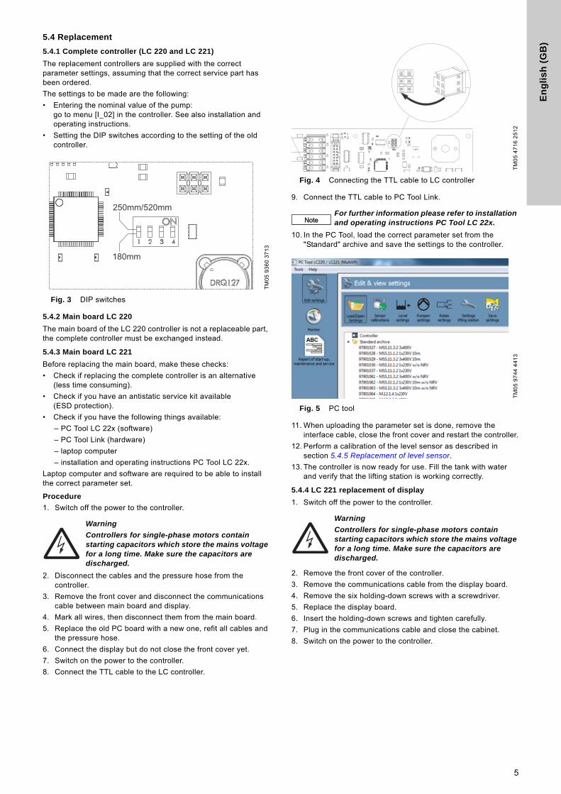
5.4.1 Complete controller (LC 220 and LC 221)
The replacement controllers are supplied with the correct parameter settings, assuming that the correct service part has been ordered.
The settings to be made are the following:
• Entering the nominal value of the pump: go to menu [I_02] in the controller. See also installation and operating instructions.
• Setting the DIP switches according to the setting of the old controller.
Fig. 3 DIP switches
5.4.2 Main board LC 220
The main board of the LC 220 controller is not a replaceable part, the complete controller must be exchanged instead.
5.4.3 Main board LC 221
Before replacing the main board, make these checks:
• Check if replacing the complete controller is an alternative (less time consuming).
• Check if you have an antistatic service kit available(ESD protection).
• Check if you have the following things available:
– PC Tool LC 22x (software)
– PC Tool Link (hardware)
– laptop computer
– installation and operating instructions PC Tool LC 22x.
Laptop computer and software are required to be able to install the correct parameter set.
Procedure
1. Switch off the power to the controller.
2. Disconnect the cables and the pressure hose from the controller.
3. Remove the front cover and disconnect the communications cable between main board and display.
4. Mark all wires, then disconnect them from the main board.
5. Replace the old PC board with a new one, refit all cables and the pressure hose.
6. Connect the display but do not close the front cover yet.
7. Switch on the power to the controller.
8. Connect the TTL cable to the LC controller.
Fig. 4 Connecting the TTL cable to LC controller
9. Connect the TTL cable to PC Tool Link.
10. In the PC Tool, load the correct parameter set from the "Standard" archive and save the settings to the controller.
Fig. 5 PC tool
11. When uploading the parameter set is done, remove the interface cable, close the front cover and restart the controller.
12. Perform a calibration of the level sensor as described in section 5.4.5 Replacement of level sensor.
13. The controller is now ready for use. Fill the tank with water and verify that the lifting station is working correctly.
5.4.4 LC 221 replacement of display
1. Switch off the power to the controller.
2. Remove the front cover of the controller.
3. Remove the communications cable from the display board.
4. Remove the six holding-down screws with a screwdriver.
5. Replace the display board.
6. Insert the holding-down screws and tighten carefully.
7. Plug in the communications cable and close the cabinet.
8. Switch on the power to the controller.
TM
05
93
60
37
13
Warning
Controllers for single-phase motors contain starting capacitors which store the mains voltage for a long time. Make sure the capacitors are discharged.
250mm/520mm
180mm
TM
05
47
16
25
12
NoteFor further information please refer to installation and operating instructions PC Tool LC 22x.
TM
05
97
44
44
13
Warning
Controllers for single-phase motors contain starting capacitors which store the mains voltage for a long time. Make sure the capacitors are discharged.
5
En
glis
h (G
B)
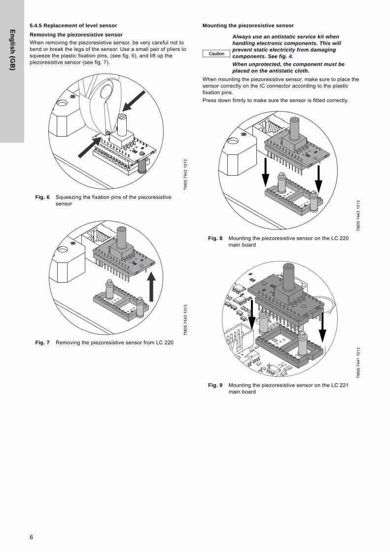
5.4.5 Replacement of level sensor
Removing the piezoresistive sensor
When removing the piezoresistive sensor, be very careful not to bend or break the legs of the sensor. Use a small pair of pliers to squeeze the plastic fixation pins, (see fig. 6), and lift up the piezoresistive sensor (see fig. 7).
Fig. 6 Squeezing the fixation pins of the piezoresistive sensor
Fig. 7 Removing the piezoresistive sensor from LC 220
Mounting the piezoresistive sensor
When mounting the piezoresistive sensor, make sure to place the sensor correctly on the IC connector according to the plastic fixation pins.
Press down firmly to make sure the sensor is fitted correctly.
Fig. 8 Mounting the piezoresistive sensor on the LC 220 main board
Fig. 9 Mounting the piezoresistive sensor on the LC 221 main board
TM
05
74
42
10
13
TM
05
74
43
10
13
Caution
Always use an antistatic service kit when handling electronic components. This will prevent static electricity from damaging components. See fig. 4.
When unprotected, the component must be placed on the antistatic cloth.
TM
05
74
43
10
13
TM
05
74
41
10
13
6
En
gli
sh
(G
B)
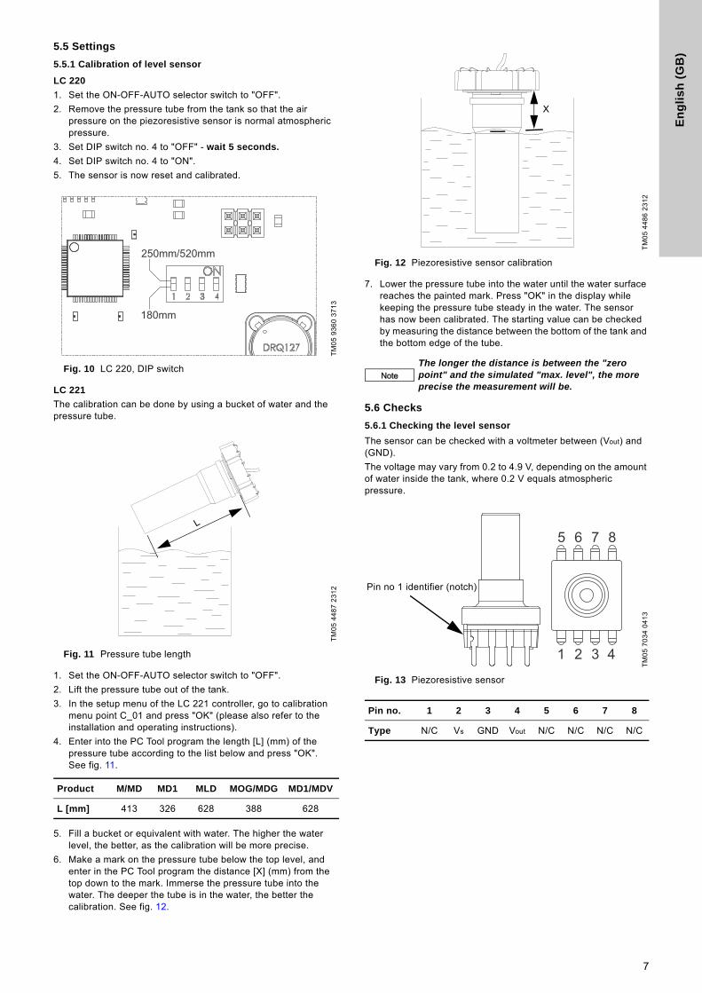
5.5 Settings
5.5.1 Calibration of level sensor
LC 220
1. Set the ON-OFF-AUTO selector switch to "OFF".
2. Remove the pressure tube from the tank so that the air pressure on the piezoresistive sensor is normal atmospheric pressure.
3. Set DIP switch no. 4 to "OFF" - wait 5 seconds.
4. Set DIP switch no. 4 to "ON".
5. The sensor is now reset and calibrated.
Fig. 10 LC 220, DIP switch
LC 221
The calibration can be done by using a bucket of water and the pressure tube.
Fig. 11 Pressure tube length
1. Set the ON-OFF-AUTO selector switch to "OFF".
2. Lift the pressure tube out of the tank.
3. In the setup menu of the LC 221 controller, go to calibration menu point C_01 and press "OK" (please also refer to the installation and operating instructions).
4. Enter into the PC Tool program the length [L] (mm) of the pressure tube according to the list below and press "OK". See fig. 11.
5. Fill a bucket or equivalent with water. The higher the water level, the better, as the calibration will be more precise.
6. Make a mark on the pressure tube below the top level, and enter in the PC Tool program the distance [X] (mm) from the top down to the mark. Immerse the pressure tube into the water. The deeper the tube is in the water, the better the calibration. See fig. 12.
Fig. 12 Piezoresistive sensor calibration
7. Lower the pressure tube into the water until the water surface reaches the painted mark. Press "OK" in the display while keeping the pressure tube steady in the water. The sensor has now been calibrated. The starting value can be checked by measuring the distance between the bottom of the tank and the bottom edge of the tube.
5.6 Checks
5.6.1 Checking the level sensor
The sensor can be checked with a voltmeter between (Vout) and (GND).
The voltage may vary from 0.2 to 4.9 V, depending on the amount of water inside the tank, where 0.2 V equals atmospheric pressure.
Fig. 13 Piezoresistive sensor
TM
05
93
60
37
13
TM
05
44
87
23
12
Product M/MD MD1 MLD MOG/MDG MD1/MDV
L [mm] 413 326 628 388 628
250mm/520mm
180mm
L
TM
05
44
86
23
12
NoteThe longer the distance is between the "zero point" and the simulated "max. level", the more precise the measurement will be.
TM
05
70
34
04
13
Pin no. 1 2 3 4 5 6 7 8
Type N/C Vs GND Vout N/C N/C N/C N/C
X
Pin no 1 identifier (notch)
1 2 3 4
5 6 7 8
7

En
glis
h (G
B)
6. Fault finding
6.1 Fault finding of LC 220
Emergency operating mode by controller:
To prevent the pump from overheating, a runtime limitation will stop the pump after 60 seconds of operation to cool down for 600 seconds before starting up again. These cycles will continue as long as the water level is higher than the stop level. The times are according to intermittent operation S3 10 %, 1 min. Note: Normal operating time for MSS is max. 8 seconds.
Motor protection inside the motor:
Single- and three-phase motors are protected by a thermal switch in the windings and an additional thermal circuit breaker to cut out the motor in case of overload.
Warning
Before carrying out maintenance and service on lifting stations used for pumping liquids which might be hazardous to health, make sure that the lifting station has been thoroughly flushed with clean water and that the discharge pipe has been drained. Rinse the parts in water after dismantling. Make sure that the isolating valves have been closed. The work must be carried out in accordance with local regulations.
Warning
Before making any connections in the LC 220 or LC 221 or working on lifting stations, make sure that the power supply has been switched off and that it cannot be accidentally switched on.
Fault LED indication Cause Remedy
1. Pump does not run in AUTO mode, and the water level is rising Green power LED is on.
Red pump LED is on.The thermal switch has cut out the pump.
Allow the pump to cool down. After cooling down, the pump will restart automatically, unless LC 220 has been set to manual restarting. If so, shift the ON-OFF-AUTO selector switch to position OFF (O) for a short period.
Green power LED is on.The level measurement fails, the sensor gives wrong signal.
Check for possible leaks between pressure hose and bulkhead connector at the controller cabinet. See section 5.6.1 Checking the level sensor.
- Defective main board Replace controller.
Green power LED is on.The new DIP switch setting does not work correctly.
Switch off the power supply to the controller for 1 minute and switch it on again.
Green pump symbol LED is ON and is red (flashing) or gets red after 60 seconds (buzzer is active).
Thermal switch inside the motor has stopped the pump.
Switch to OFF mode and wait 10 minutes until the pump has cooled down. Then try to empty the tank again in AUTO mode. Measure motor winding resistances.
Phase sequence failure light is ON (long time after setup at installation).
The phase sequence of the mains supply was changed. Check if any electrical installation was recently made.
Change phase sequence of CEE plug (see fig. 14) or of mains supply.
2. Pump operates in intervals with starts and stops.
Pump operates approx.1 minute and stops for some minutes (red LED is flashing, buzzer is active), operates again (green LED is on).
Emergency operating mode by controller is active.
a) Check the ON-OFF-AUTO switch. If it is accidentally set to ON, the controller will prevent the pump from continuous operation.
b) The discharge pipe is blocked. Check the non-return valve, the isolating valve and the pipework.
c) The pump housing vent is blocked. Check vent and remove blockage.
3. Pump does not run in ON mode.
Phase sequence failure. Wrong phase sequence.Change phase sequence of CEE plug or mains supply (see fig. 14).
4. Wastewater flows back to sanitary appliances. Pump always starts at a higher level than required.
Normal indications with no visible failure.
The starting level is higher than required.
Check if the lowest starting level at 180 mm is correctly set: Check DIP switch setting. If the starting level of 180 mm is too high, it can be set to an absolute minimum of 150 mm using the PC Tool LC 22x (call Grundfos Service). If this level is still too high, check the installation of the sanitary appliance and the use of a Sololift2 unit for the lowest sanitary appliance installed.
5. Pump starts at different water levels or does not start regularly. Normal indications with
no visible failure.DIP switch 4 is in calibration position OFF.
Check DIP switch 4 and change setting to ON position.IMPORTANT: When changing the DIP switch to ON position, the pressure tube inside the tank must not be submerged. Otherwise the calibration will fail.
8

En
gli
sh
(G
B)
6. Recurrent acoustic alarm.
No fault is indicated.
Most alarms (e.g. high water, sensor) are reset automatically when controller is in automatic reset mode (DIP switch 2).
Automatically reset faults can only be read out by the PC Tool LC 22x.
7. No pump operation. Acoustic alarm and switch symbols are ON.
Red switch symbol LED is ON and buzzer is active.
An external switch (e.g. high water level switch as flooding indication or another switch) outside the lifting station is closed.
Check the installation around the lifting station and any flooding protection switches connected to the controller.
8. The pump starts and stops too often, even if there is no inflow.
The level measurement fails, the sensor gives wrong signal.
Check for possible leaks between pressure hose and bulkhead connector at the controller cabinet. The pressure hose must be inserted up to the stop (approx. 15 mm).
9. The pump starts sometimes without apparent reason.
Test run 24 hours after last operation.
No action necessary. It is a safety function preventing the shaft seal from seizing up.
10. From time to time the pump runs longer than usual Every tenth time the pump runs
two seconds longer.
No action necessary. It is a feature of the LC 220 / 221 controllers letting the pumps run longer to ensure that the pressure tube is emptied.
Fault LED indication Cause Remedy
9

En
glis
h (G
B)
6.2 Fault finding of LC 221
Fault Indication at display Cause Remedy
1. Pump does not run in AUTO mode, and the water level is rising.
LCD is dark, no symbol and no LED is ON.
The power supply cable is broken, or loose contact.
Check power supply cable and terminal block inside controller.
LCD is dark, no symbol and no LED is ON.
Control circuit fuses are blown. Replace blown fuses.
LCD is dark, no symbol and no LED is ON, but the buzzer is active.
LCD board or cable with RJ45 plug is defective.
Replace LCD board or check cable(with RJ45 plugs).
– Green power symbol LED is on.
– Water level on display does not correspond to level in tank.
– No pump operation is indicated.
The level measurement fails.
Check for possible leaks between pressure hose and bulkhead connector at the controller cabinet. See section 5.6.1 Checking the level sensor.
– Green power symbol LED is on.
– Water level on display corresponds to level in tank.
– No pump operation is indicated.
Wrong setting for maximum level.
Correct sensor setting. See section 5.5.1 Calibration of level sensor.
– Pump symbol(s) flashing.
– Buzzer is active.
– TEMP is displayed.
– Thermal switch symbol displayed.
Thermal switch inside the motor has stopped the pump.
Switch to OFF mode and wait 10 minutes until the pump has cooled down. Then try to empty the tank again in AUTO mode. Measure motor winding resistances.
– Pump symbol(s) flashing.
– F007..F008 displayed or
– RELAY displayed.
Pump overcurrent because of blockage or worn/defective impeller.
– Remove blockage.
– Check pump.
Phase sequence failure light is ON (long time after setup at installation).
The phase sequence of the mains supply was changed, or a phase is missing. Check if any change at the electrical installation was made recently.
– Check for changes of electrical installation.
– Change phase sequence of CEE plug or mains supply (see fig. 14).
SENSOR, F005 or F006
Check for possible leaks between pressure hose and bulkhead connector at the controller cabinet. The pressure hose must be inserted up to the stop (approx. 15 mm).
2. Pump operates in intervals being started (one minute) and stopped (several minutes) and then operates again. Pump fault is indicated at
LCD and buzzer is active.Emergency operating mode by controller is active.
a) Check the ON-OFF-AUTO switch. If it is accidentally set to ON, the controller will prevent the pump from continuous operation.
b) The discharge pipe is blocked. Check the non-return valve, the isolating valve and the pipework.
c) The pump housing vent is blocked. Check vent and remove blockage.
10

En
gli
sh
(G
B)
3. The pump starts and stops too often, even if there is no inflow.
The level measurement fails, the sensor gives wrong signal.
Check for possible leaks between pressure hose and bulkhead connector at the controller cabinet. See section 5.6.1 Checking the level sensor.
F011 and/or F012 pump and time symbols flashing
The operating time protection is activated. If the pump runs for longer than 3 minutes, a protection program of the controller will stop the pump for 3 minutes and the other pump will take over. At the next start impulse, the first pump will be activated again. If the venting problem persists, the pump will be stopped after 3 minutes and so on.
Check that the discharge valve is completely opened. Check the pump housing vent. If blocked, clean the vent hole.
TEMP F005 and/or F006The thermal switch has cut out the pump
Allow the pump to cool down. After cooling down, the pump will restart automatically, unless LC 221 has been set to manual restarting. Check the inflow parameters and the non-return valve. A high number of starts without cooling time in between over a longer period can cause thermal cut-out. Consider S3 duty.
4. The pump starts sometimes without apparent reason.
Normal indications with no visible failure.
Test run 24 hours after last operation.
No action necessary. It is a safety function that prevents the shaft seal from seizing up.
5. From time to time the pump runs longer than usual.
Normal indications with no visible failure.
Safety feature of the controller. Every tenth time the pump runs two seconds longer to remove all liquid from the pressure tube.
No action necessary.
6. Wastewater flows back to sanitary appliances.Pump always starts at a higher level than required.
Normal indications with no visible failure.
The start level is higher than required.
Check if the lowest start level is correctly set. If not, correct setting.
7. The pump operating time exceeds time from last observation (8 < x < 60 sec.).
Normal indications with no visible failure.
Pump housing vent may be blocked. Pump start is delayed.
a) Remove the (partially) blocked pump housing vent.
b) Check pump hydraulics for partial blockage.
8. Recurrent acoustic alarm.At observation, no failure is indicated.
Most alarms (e.g. high water, sensor) are reset automatically when in automatic reset mode (A_01).
The last 20 faults are stored in the fault log.
9. No pump operation. Acoustic alarm is indicated.
EXTERN is displayed and buzzer is active.
An external switch (e.g. high water level switch as flooding indication or another switch) outside the lifting station is closed.
Check the installation around the lifting station and any flooding protection switches connected to the controller.
10. No pump operation. Acoustic alarm is indicated.
SENSOR is displayed (fault code F004).
The level measurement fails, the sensor gives wrong signal.
Check the sensor setting and/or voltages and replace sensor if necessary.See section 5.6 Checks.
Fault Indication at display Cause Remedy
11

En
glis
h (G
B)
7. Wiring diagrams
Fig. 14 Wiring diagram, single-phase Multilift MSS
Fig. 15 Wiring diagram, three-phase Multilift MSS
Fig. 16 Wiring diagram, single-phase Multilift M.12.1.4 and M.15.1.4
Fig. 17 Wiring diagram, three-phase Multilift M.12.3.4 and M.15.3.4
Fig. 18 Wiring diagram, three-phase Multilift M.22.3.4 with contactors
Fig. 19 Wiring diagram, three-phase Multilift M.22.3.4, M.24.3.2, M.32.3.2 and M.38.3.2 with motor-protective circuit breaker
TM
05
14
02
27
11T
M0
5 1
40
3 2
711
TM
05
19
41
40
11
TM
05
34
56
15
12
TM
05
19
42
40
11T
M0
5 1
94
3 4
011
12
En
gli
sh
(G
B)
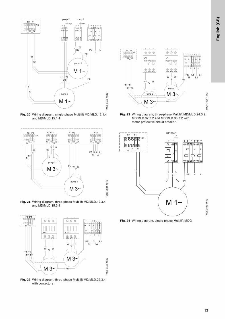
Fig. 20 Wiring diagram, single-phase Multilift MD/MLD.12.1.4 and MD/MLD.15.1.4
Fig. 21 Wiring diagram, three-phase Multilift MD/MLD.12.3.4 and MD/MLD.15.3.4
Fig. 22 Wiring diagram, three-phase Multilift MD/MLD.22.3.4 with contactors
Fig. 23 Wiring diagram, three-phase Multilift MD/MLD.24.3.2, MD/MLD.32.3.2 and MD/MLD.38.3.2 with motor-protective circuit breaker
Fig. 24 Wiring diagram, single-phase Multilift MOG
TM
05
35
93
16
12
TM
05
35
94
16
12
TM
05
35
95
16
12
TM
05
35
96
16
12
TM
05
38
19
16
12
30/150μF
5
T1T2
T1T2
61
23
PE
PE
N L
PE N L
M 1~
P2 P1X6
Q1
U2Z2
13

En
glis
h (G
B)
Fig. 25 Wiring diagram, single-phase Multilift MDG
Fig. 26 Wiring diagram, three-phase Multilift MOG
Fig. 27 Wiring diagram, three-phase Multilift MDG
Fig. 28 Wiring diagram, three-phase DOL (< 5 kW) for Multilift MD1 and MDV
Fig. 29 Wiring diagram, three-phase Y/D (> 5 kW) for Multilift MD1 and MDV
TM
05
38
16
16
12
TM
05
38
18
16
12
TM
05
38
17
16
21
30/150μF
PE
1
5
T1 T2 T1 T2
5
662
3
12
3 PE
PE N L
PE N L
M 1~
M 1~
pump 2
pump 1
pump 1pump 2P2 P1
X6
Q2U2
Z2
Q1U2
Z2
T1
2T1
T2
4T2 6T3
T1 T2
12
3
5
6
PE
PE
PE
N
N
L3
L3
L2
L2
L1
L1
M 3~
Q1Motor protection
P1P2X6
P1P2
5
T1
2T1
T2
4T2 6T3 2T1 4T2 6T3
T1 T2
5
661
23
12
3PE
PE
PE
PE
N
N
L3
L3
L2
L2
L1
L1
M 3~M 3~
pump 2
pump 1
X6
Q2 Q1Motor protection Motor protection
TM
05
40
43
20
12
TM
05
40
44
20
12
PE
u v w(T3)(T1) (T2)
u v w(T3)(T1) (T2)
L1 NL2 L3
L1 NL2 L3 PE
3~
3~ Option
Option
U1 V1 W1 U2 V2 W2
T11 T21
U V W WVU
T11 T211 3 5 4 6 2 7 8 91 2 3 4 5 6
14

Gru
nd
fos
co
mp
anie
s
ArgentinaBombas GRUNDFOS de Argentina S.A.Ruta Panamericana km. 37.500 Centro Industrial Garin1619 Garín Pcia. de B.A.Phone: +54-3327 414 444Telefax: +54-3327 45 3190
AustraliaGRUNDFOS Pumps Pty. Ltd. P.O. Box 2040 Regency Park South Australia 5942 Phone: +61-8-8461-4611 Telefax: +61-8-8340 0155
AustriaGRUNDFOS Pumpen Vertrieb Ges.m.b.H.Grundfosstraße 2 A-5082 Grödig/Salzburg Tel.: +43-6246-883-0 Telefax: +43-6246-883-30
BelgiumN.V. GRUNDFOS Bellux S.A. Boomsesteenweg 81-83 B-2630 Aartselaar Tél.: +32-3-870 7300 Télécopie: +32-3-870 7301
BelarusПредставительство ГРУНДФОС в Минске220125, Минскул. Шафарнянская, 11, оф. 56, БЦ «Порт»Тел.: +7 (375 17) 286 39 72/73Факс: +7 (375 17) 286 39 71E-mail: [email protected]
Bosna and HerzegovinaGRUNDFOS SarajevoZmaja od Bosne 7-7A,BH-71000 SarajevoPhone: +387 33 592 480Telefax: +387 33 590 465www.ba.grundfos.come-mail: [email protected]
BrazilBOMBAS GRUNDFOS DO BRASILAv. Humberto de Alencar Castelo Branco, 630CEP 09850 - 300São Bernardo do Campo - SPPhone: +55-11 4393 5533Telefax: +55-11 4343 5015
BulgariaGrundfos Bulgaria EOODSlatina DistrictIztochna Tangenta street no. 100BG - 1592 SofiaTel. +359 2 49 22 200Fax. +359 2 49 22 201email: [email protected]
CanadaGRUNDFOS Canada Inc. 2941 Brighton Road Oakville, Ontario L6H 6C9 Phone: +1-905 829 9533 Telefax: +1-905 829 9512
ChinaGRUNDFOS Pumps (Shanghai) Co. Ltd.50/F Maxdo Center No. 8 XingYi Rd.Hongqiao development ZoneShanghai 200336PRCPhone: +86 21 612 252 22Telefax: +86 21 612 253 33
CroatiaGRUNDFOS CROATIA d.o.o.Buzinski prilaz 38, BuzinHR-10010 ZagrebPhone: +385 1 6595 400 Telefax: +385 1 6595 499www.hr.grundfos.com
Czech RepublicGRUNDFOS s.r.o.Čajkovského 21779 00 OlomoucPhone: +420-585-716 111Telefax: +420-585-716 299
DenmarkGRUNDFOS DK A/S Martin Bachs Vej 3 DK-8850 Bjerringbro Tlf.: +45-87 50 50 50 Telefax: +45-87 50 51 51 E-mail: [email protected]/DK
EstoniaGRUNDFOS Pumps Eesti OÜPeterburi tee 92G11415 TallinnTel: + 372 606 1690Fax: + 372 606 1691
FinlandOY GRUNDFOS Pumput AB Mestarintie 11 FIN-01730 Vantaa Phone: +358-(0)207 889 900Telefax: +358-(0)207 889 550
FrancePompes GRUNDFOS Distribution S.A. Parc d’Activités de Chesnes 57, rue de Malacombe F-38290 St. Quentin Fallavier (Lyon) Tél.: +33-4 74 82 15 15 Télécopie: +33-4 74 94 10 51
GermanyGRUNDFOS GMBHSchlüterstr. 3340699 ErkrathTel.: +49-(0) 211 929 69-0 Telefax: +49-(0) 211 929 69-3799e-mail: [email protected] in Deutschland:e-mail: [email protected]
HILGE GmbH & Co. KGHilgestrasse 37-4755292 Bodenheim/RheinGermanyTel.: +49 6135 75-0Telefax: +49 6135 1737e-mail: [email protected]
GreeceGRUNDFOS Hellas A.E.B.E. 20th km. Athinon-Markopoulou Av. P.O. Box 71 GR-19002 Peania Phone: +0030-210-66 83 400 Telefax: +0030-210-66 46 273
Hong KongGRUNDFOS Pumps (Hong Kong) Ltd. Unit 1, Ground floor Siu Wai Industrial Centre 29-33 Wing Hong Street & 68 King Lam Street, Cheung Sha Wan Kowloon Phone: +852-27861706 / 27861741 Telefax: +852-27858664
HungaryGRUNDFOS Hungária Kft.Park u. 8H-2045 Törökbálint, Phone: +36-23 511 110Telefax: +36-23 511 111
IndiaGRUNDFOS Pumps India Private Limited118 Old Mahabalipuram RoadThoraipakkamChennai 600 096Phone: +91-44 2496 6800
IndonesiaPT GRUNDFOS Pompa Jl. Rawa Sumur III, Blok III / CC-1 Kawasan Industri, Pulogadung Jakarta 13930 Phone: +62-21-460 6909 Telefax: +62-21-460 6910 / 460 6901
IrelandGRUNDFOS (Ireland) Ltd. Unit A, Merrywell Business ParkBallymount Road LowerDublin 12 Phone: +353-1-4089 800 Telefax: +353-1-4089 830
ItalyGRUNDFOS Pompe Italia S.r.l. Via Gran Sasso 4I-20060 Truccazzano (Milano)Tel.: +39-02-95838112 Telefax: +39-02-95309290 / 95838461
JapanGRUNDFOS Pumps K.K.Gotanda Metalion Bldg., 5F, 5-21-15, Higashi-gotandaShiagawa-ku, Tokyo141-0022 JapanPhone: +81 35 448 1391Telefax: +81 35 448 9619
KoreaGRUNDFOS Pumps Korea Ltd.6th Floor, Aju Building 679-5Yeoksam-dong, Kangnam-ku, 135-916Seoul, KoreaPhone: +82-2-5317 600Telefax: +82-2-5633 725
LatviaSIA GRUNDFOS Pumps Latvia Deglava biznesa centrsAugusta Deglava ielā 60, LV-1035, Rīga,Tālr.: + 371 714 9640, 7 149 641Fakss: + 371 914 9646
LithuaniaGRUNDFOS Pumps UABSmolensko g. 6LT-03201 VilniusTel: + 370 52 395 430Fax: + 370 52 395 431
MalaysiaGRUNDFOS Pumps Sdn. Bhd.7 Jalan Peguam U1/25Glenmarie Industrial Park40150 Shah AlamSelangor Phone: +60-3-5569 2922Telefax: +60-3-5569 2866
MexicoBombas GRUNDFOS de México S.A. de C.V. Boulevard TLC No. 15Parque Industrial Stiva AeropuertoApodaca, N.L. 66600Phone: +52-81-8144 4000 Telefax: +52-81-8144 4010
NetherlandsGRUNDFOS NetherlandsVeluwezoom 351326 AE AlmerePostbus 220151302 CA ALMERE Tel.: +31-88-478 6336 Telefax: +31-88-478 6332E-mail: [email protected]
New ZealandGRUNDFOS Pumps NZ Ltd.17 Beatrice Tinsley CrescentNorth Harbour Industrial EstateAlbany, AucklandPhone: +64-9-415 3240Telefax: +64-9-415 3250
NorwayGRUNDFOS Pumper A/S Strømsveien 344 Postboks 235, Leirdal N-1011 Oslo Tlf.: +47-22 90 47 00 Telefax: +47-22 32 21 50
PolandGRUNDFOS Pompy Sp. z o.o.ul. Klonowa 23Baranowo k. PoznaniaPL-62-081 PrzeźmierowoTel: (+48-61) 650 13 00Fax: (+48-61) 650 13 50
PortugalBombas GRUNDFOS Portugal, S.A. Rua Calvet de Magalhães, 241Apartado 1079P-2770-153 Paço de ArcosTel.: +351-21-440 76 00Telefax: +351-21-440 76 90
RomaniaGRUNDFOS Pompe România SRLBd. Biruintei, nr 103 Pantelimon county IlfovPhone: +40 21 200 4100Telefax: +40 21 200 4101E-mail: [email protected]
RussiaООО Грундфос Россия109544, г. Москва, ул. Школьная, 39-41, стр. 1Тел. (+7) 495 564-88-00 (495) 737-30-00Факс (+7) 495 564 88 11E-mail [email protected]
Serbia Grundfos Srbija d.o.o.Omladinskih brigada 90b11070 Novi Beograd Phone: +381 11 2258 740Telefax: +381 11 2281 769www.rs.grundfos.com
SingaporeGRUNDFOS (Singapore) Pte. Ltd.25 Jalan Tukang Singapore 619264 Phone: +65-6681 9688 Telefax: +65-6681 9689
SloveniaGRUNDFOS d.o.o.Šlandrova 8b, SI-1231 Ljubljana-ČrnučePhone: +386 31 718 808Telefax: +386 (0)1 5680 619E-mail: [email protected]
South AfricaGRUNDFOS (PTY) LTDCorner Mountjoy and George Allen RoadsWilbart Ext. 2Bedfordview 2008Phone: (+27) 11 579 4800Fax: (+27) 11 455 6066E-mail: [email protected]
SpainBombas GRUNDFOS España S.A. Camino de la Fuentecilla, s/n E-28110 Algete (Madrid) Tel.: +34-91-848 8800 Telefax: +34-91-628 0465
SwedenGRUNDFOS AB Box 333 (Lunnagårdsgatan 6) 431 24 Mölndal Tel.: +46 31 332 23 000Telefax: +46 31 331 94 60
SwitzerlandGRUNDFOS Pumpen AG Bruggacherstrasse 10 CH-8117 Fällanden/ZH Tel.: +41-44-806 8111 Telefax: +41-44-806 8115
TaiwanGRUNDFOS Pumps (Taiwan) Ltd. 7 Floor, 219 Min-Chuan Road Taichung, Taiwan, R.O.C. Phone: +886-4-2305 0868Telefax: +886-4-2305 0878
ThailandGRUNDFOS (Thailand) Ltd. 92 Chaloem Phrakiat Rama 9 Road,Dokmai, Pravej, Bangkok 10250Phone: +66-2-725 8999Telefax: +66-2-725 8998
TurkeyGRUNDFOS POMPA San. ve Tic. Ltd. Sti.Gebze Organize Sanayi Bölgesi Ihsan dede Caddesi,2. yol 200. Sokak No. 20441490 Gebze/ KocaeliPhone: +90 - 262-679 7979Telefax: +90 - 262-679 7905E-mail: [email protected]
UkraineБізнес Центр ЄвропаСтоличне шосе, 103м. Київ, 03131, Україна Телефон: (+38 044) 237 04 00 Факс.: (+38 044) 237 04 01E-mail: [email protected]
United Arab EmiratesGRUNDFOS Gulf DistributionP.O. Box 16768Jebel Ali Free ZoneDubaiPhone: +971 4 8815 166Telefax: +971 4 8815 136
United KingdomGRUNDFOS Pumps Ltd. Grovebury Road Leighton Buzzard/Beds. LU7 4TL Phone: +44-1525-850000 Telefax: +44-1525-850011
U.S.A.GRUNDFOS Pumps Corporation 17100 West 118th TerraceOlathe, Kansas 66061Phone: +1-913-227-3400 Telefax: +1-913-227-3500
UzbekistanGrundfos Tashkent, Uzbekistan The Repre-sentative Office of Grundfos Kazakhstan in Uzbekistan38a, Oybek street, TashkentТелефон: (+998) 71 150 3290 / 71 150 3291Факс: (+998) 71 150 3292
Addresses Revised 11.03.2014

98631979 0314
ECM: 1131155 The
nam
e G
rund
fos,
the
Gru
ndfo
s lo
go, a
nd b
e t
hin
k i
nn
ov
ate
are
regi
ster
ed tr
adem
arks
ow
ned
by G
rund
fos
Hol
ding
A/S
or G
rund
fos
A/S,
Den
mar
k. A
ll rig
hts
rese
rved
wor
ldw
ide.
© C
opyr
ight
Gru
ndfo
s H
oldi
ng A
/S
www.grundfos.com