Embed Size (px)
Citation preview
UNOLIFT, DUOLIFTInstallation and operating instructions
GRUNDFOS INSTRUCTIONS

2
En
glis
h (
GB
)
3
English (GB) Installation and operating instructions
Original installation and operating instructions
These installation and operating instructions describe Grundfos Unolift and Duolift lifting stations. They apply to the tank and installation kits. For detailed information on installing and operating the pumps and controller, see the installation and operating instructions supplied with these products.
Sections 1-6 give the information necessary to be able to unpack, install and start up the product in a safe way.
Sections 7-16 give important information about the product, as well as information on service, fault finding and disposal of the product.
CONTENTSPage
1. General information
1.1 Symbols used in this document
1.2 Symbols on the product
2. Receiving the product
2.1 Transporting the product
1. General information 31.1 Symbols used in this document 31.2 Symbols on the product 3
2. Receiving the product 32.1 Transporting the product 32.2 Inspecting the product 42.3 Scope of delivery 4
3. Installing the product 63.1 General guidelines 63.2 Choice of tank inlets 63.3 Location 63.4 Tools 83.5 Installation overview 83.6 Positioning the product 83.7 Installing the tank 83.8 Drilling holes in the tank 83.9 Fitting the cable glands 93.10 Fitting the air vent 93.11 Fitting the venting pipe 93.12 Connecting the inlet pipes 93.13 Installing the pump in the tank 103.14 Inner connecting pipes 103.15 Installing the level sensor tube 133.16 Installing an alarm float switch 133.17 Assembling the discharge pipes 133.18 Installing a diaphragm pump 153.19 Installing the controller 153.20 Electrical connection 153.21 Setting the controller before start-up 154. Starting up the product 165. Monitor the increasing liquid level in the
tank up to the start level and check that the pumps start and stop at least twice. 16
4.3 Storing the product 164.4 Storing the product 16
5. Product introduction 175.1 Product overview 175.2 Applications 175.3 Pumped liquids 175.4 Automatic operation 17
5.5 Identification 185.6 Diaphragm pump 185.7 Level sensor tube 18
6. Operating the product 196.1 Setting the start levels 19
7. Starting up the product after standstill 21
8. Servicing the product 21
9. Taking the product out of operation 21
10. Technical data 2210.1 Operating conditions 2210.2 Material 2210.3 Electrical data 2210.4 Dimensions and weights 22
11. Fault finding the product 23
12. Disposing of the product 25
Prior to installation, read this document. Installation and operation must comply with local regulations and accepted codes of good practice.
DANGER
Indicates a hazardous situation which, if not avoided, will result in death or serious personal injury.
WARNING
Indicates a hazardous situation which, if not avoided, could result in death or serious personal injury.
CAUTION
Indicates a hazardous situation which, if not avoided, could result in minor or moderate personal injury.
European Conformity
WARNING
Falling objects• Death or serious personal injury• Secure the product during
transportation to prevent it from tilting or falling down.
En
glish
(GB
)
4
2.2 Inspecting the product
1. Check that the product is as ordered.
2. Check that no visible parts have been damaged.
3. If parts are damaged or missing, contact your local Grundfos sales company and refer to the product numbers in section 2.3 Scope of delivery.
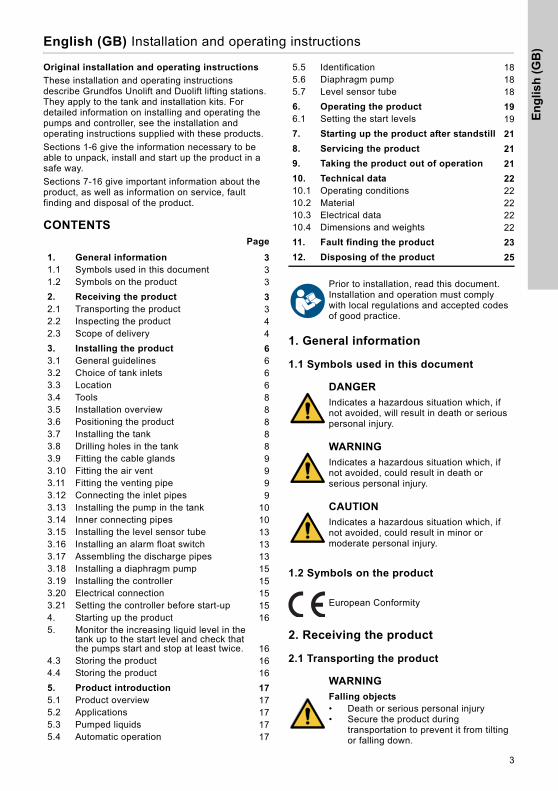
2.3 Scope of delivery
The scope of delivery depends on your order. Pumps, tank and pipework are delivered separately and are to be assembled.
Description of kits
CAUTION
Back injury• Minor or moderate personal injury• Get assistance from another person or
use lifting equipment to carry the product.
CAUTION
Crushing of feet• Minor or moderate personal injury• Wear safety shoes when moving the
product.
Tank
Designation
Quantity
270 litres tank
540 litres tank
Tank 1 1
Cover with gasket 1 2
Screw, M8 x 30 12 24
Washer 12 24
Fastening brackets for level sensor tube
2 2
Screws for fixing tank 4 4
Plugs for fixing tank 4 4
Socket seal, DN 40 1 1
Socket seal, DN 100 1 1
Inner connection pipes
Designation
Quantity
KP/CC
SEG APB
Adaptor Rp 2 - R 1 1/2
1 1 -
Double socket R 2 - R 2
1 1 1
Nut, PVC, 2" 1 1 1
O-Ring Ø60,EPDM
- - 1
Nozzle adaptor, F
2 2 2
Clamp, stainless steel
2 2 2
Flexible connecting piece ∅50
1 1 1
Elbow 90° - 1 1
Flange ∅50 - 1 -
Screw,for flange
- 4 -
Washer,for flange
- 8 -
Inner connection pipes
Designation
Quantity
KP/CC
SEG APB
En
glis
h (
GB
)
5
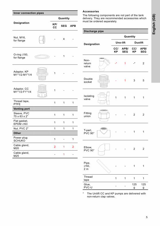
Accessories
The following components are not part of the tank delivery. They are recommended accessories which must be ordered separately.
* The Unilift CC and KP pumps are delivered with non-return clap valves.
Nut, M16,for flange
- 4 -
O-ring ∅50,for flange
- 1 -
Adaptor, KP M1"1/2-M1"1/4
1 - -
Adaptor, CC M1"1/2-F1"1/4
1 - -
Thread tape, PTFE
1 1 1
Venting port
Sleeve, PVC 75 x 63 x 2"
1 1 1
Flat gasket, EPDM ∅63
1 1 1
Nut, PVC 2" 1 1 1
Other
Power plug SCHUKO
1 - 1
Cable gland, M20
2 1 2
Cable gland, M25
- 1 -
Inner connection pipes
Designation
Quantity
KP/CC
SEG APB
Discharge pipe
Designation
Quantity
Uno-lift Duolift
CC/KP
APB/SEG
CC/KP
APB/SEG
Non-return valve
-* 1 -* 2
Double socket
- 1 3 5
Isolating valve
1 1 1 1
Fitting union
- - 2 2
T-part, PVC 90°
- - 1 1
Elbow, PVC 90°
- - 2 2
Pipe, ∅50,2 m
- - 1 1
Thread tape
1 1 1 1
Glue, PVC-U
- -125
g125
g
En
glish
(GB
)
6
3. Installing the product
3.1 General guidelines
Guidelines for correct mechanical installation of lifting station are according to EN 12056-4.
• If the lifting station is installed in a basement with regular penetrating groundwater, we recommend to install a drainage pump in a separate pump sump below floor level (mandatory in certain countries). If there is only a risk of penetrating groundwater, we recommend to install a float switch outside the lifting station and to connect it a controller, which will indicate an high level alarm in case of flooding.
• The collecting tank must be fixed to the floor.
• We recommend that you connect a diaphragm pump to the collecting tank in order to be able to empty the tank manually.
• All outlet pipes from the lifting station, diaphragm pump and drainage pump must have a backwater loop, i.e. a bend above the local backwater level. Commonly, the highest point of the bend must be above street level. See fig. 2.
• Surface water must not be discharged into the lifting station inside the building. It must be collected and discharged outside the building.
• A non-return valve must be installed at the discharge of the lifting station to prevent back flow from the sewer for example.
• Install isolating valves at the inlet and outlet of the lifting station.
• The volume of the outlet pipe above the non-return valve up to the backwater loop (bend in the pipe) must be smaller than the effective tank volume.
• In general, a lifting station for black wastewater must be vented above roof level. However, it is permitted to lead the ventilation into the main building ventilation system. Special two-way venting valves must be placed outside the building.
• If the wastewater is discharged into a collecting line, the collecting line must have a filling ratio of at least h/d = 0.7. The collecting line must be at least one nominal diameter bigger after the outlet pipe connection.
• 45 degrees bends must be used to avoid sedimentation in pipework.
3.2 Choice of tank inlets
It is optimal to lead your pipework to the top inlets of the tank, as it will prevent backflow and sedimentation in the inlet pipe and give you the possibility to use a high start level for the pump. A high start level increases the effective tank volume and decreases the numbers of start/stop of the pumps.
If you use the bottom inlet, you have to select the lowest start level. If the start level is above the inlet height, there will be backflow in the inlet pipe. thus increasing the risk of sedimentation in the pipework.
3.3 Location
The lifting station must be installed in a properly lit and vented room with 60 cm free space around all parts to be serviced and operated.
The tank must not be exposed to direct sunlight. UV can affect the properties of its composite material, resulting in a shorter life.
The product is designed for indoor operation. If installed outside, it must be placed in a closed pit.
The tank can be flooded and may be installed in a basement with risk of penetrating groundwater.
En
glis
h (
GB
)
7
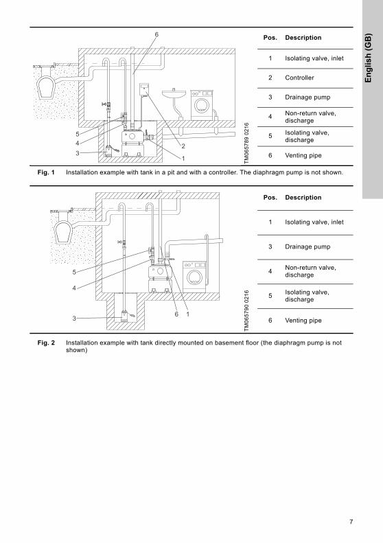
Fig. 1 Installation example with tank in a pit and with a controller. The diaphragm pump is not shown.
Fig. 2 Installation example with tank directly mounted on basement floor (the diaphragm pump is not shown)
TM
06
57
89
02
16
Pos. Description
1 Isolating valve, inlet
2 Controller
3 Drainage pump
4 Non-return valve, discharge
5 Isolating valve, discharge
6 Venting pipe
6
2345
1
TM
06
57
90
02
16
Pos. Description
1 Isolating valve, inlet
3 Drainage pump
4Non-return valve, discharge
5Isolating valve, discharge
6 Venting pipe163
4
5
En
glish
(GB
)
8
3.4 Tools
• Thread tape
• Glue
Not delivered with the product:
• Drilling machine
• Drilling bits: Ø6, Ø16, Ø25
• Cup saw: Ø40, Ø100
• Deburring tool for polyethylene
3.5 Installation overview
Depending on your product type, you must go through different steps in order to install and setup your system. The steps below are necessary steps in order to start your system. You may need to go through extra steps if you have additional accessories.
Unolift/Duolift with pumps with float switches
1. Fix tank to the floor
2. Drill holes for inlet pipes
3. Connect inlets to tank
4. Fit venting port and cable glands
5. Adjust length of float switch cable to set start levels
6. Install pumps inside tank
7. Fit inner connecting pipe
8. Fit venting pipe
9. Fit discharge pipes
Unolift/Duolift with controller and level sensor tube
1. Fix tank to the floor
2. Drill holes for inlet pipes
3. Connect inlets to tank
4. Fit venting port and cable glands
5. Install pumps inside tank
6. Install sensor tube inside tank
7. Fit inner connecting pipes
8. Fit venting pipe
9. Fit discharge pipes
3.6 Positioning the product
Position the tank so that all components are easily accessible during operation and maintenance.
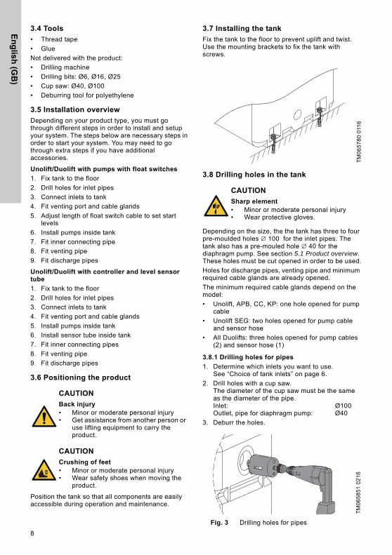
3.7 Installing the tank
Fix the tank to the floor to prevent uplift and twist. Use the mounting brackets to fix the tank with screws.
3.8 Drilling holes in the tank
Depending on the size, the the tank has three to four pre-moulded holes ∅ 100 for the inlet pipes. The tank also has a pre-mouled hole ∅ 40 for the diaphragm pump. See section 5.1 Product overview. These holes must be cut opened in order to be used.
Holes for discharge pipes, venting pipe and minimum required cable glands are already opened.
The minimum required cable glands depend on the model:
• Unolift, APB, CC, KP: one hole opened for pump cable
• Unolift SEG: two holes opened for pump cable and sensor hose
• All Duolifts: three holes opened for pump cables (2) and sensor hose (1)
3.8.1 Drilling holes for pipes
1. Determine which inlets you want to use.See “Choice of tank inlets” on page 6.
2. Drill holes with a cup saw.The diameter of the cup saw must be the same as the diameter of the pipe.Inlet: Ø100Outlet, pipe for diaphragm pump: Ø40
3. Deburr the holes.
Fig. 3 Drilling holes for pipes
CAUTION
Back injury• Minor or moderate personal injury• Get assistance from another person or
use lifting equipment to carry the product.
CAUTION
Crushing of feet• Minor or moderate personal injury• Wear safety shoes when moving the
product.
TM
06
57
80
011
6
CAUTION
Sharp element• Minor or moderate personal injury• Wear protective gloves.
TM
06
58
51
02
16
En
glis
h (
GB
)
9
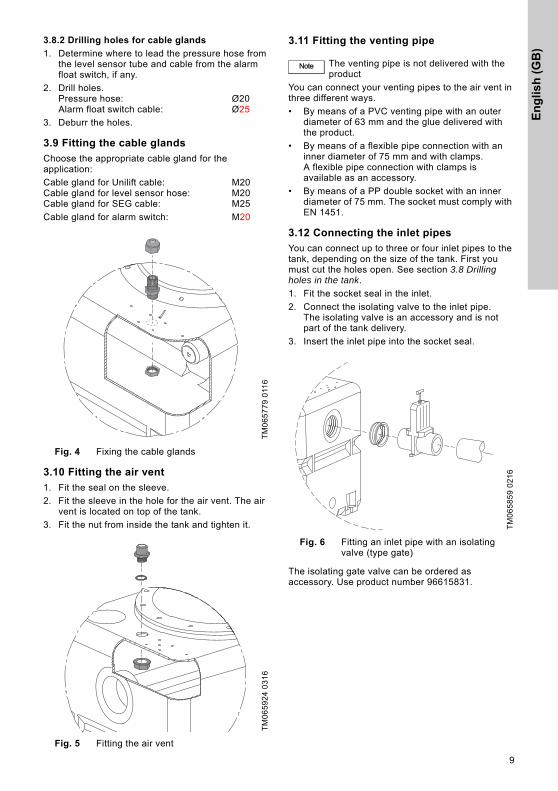
3.8.2 Drilling holes for cable glands
1. Determine where to lead the pressure hose from the level sensor tube and cable from the alarm float switch, if any.
2. Drill holes.Pressure hose: Ø20Alarm float switch cable: Ø25
3. Deburr the holes.
3.9 Fitting the cable glands
Choose the appropriate cable gland for the application:
Cable gland for Unilift cable: M20Cable gland for level sensor hose: M20Cable gland for SEG cable: M25
Cable gland for alarm switch: M20
Fig. 4 Fixing the cable glands
3.10 Fitting the air vent
1. Fit the seal on the sleeve.
2. Fit the sleeve in the hole for the air vent. The air vent is located on top of the tank.
3. Fit the nut from inside the tank and tighten it.
Fig. 5 Fitting the air vent
3.11 Fitting the venting pipe
You can connect your venting pipes to the air vent in three different ways.
• By means of a PVC venting pipe with an outer diameter of 63 mm and the glue delivered with the product.
• By means of a flexible pipe connection with an inner diameter of 75 mm and with clamps.A flexible pipe connection with clamps is available as an accessory.
• By means of a PP double socket with an inner diameter of 75 mm. The socket must comply with EN 1451.
3.12 Connecting the inlet pipes
You can connect up to three or four inlet pipes to the tank, depending on the size of the tank. First you must cut the holes open. See section 3.8 Drilling holes in the tank.
1. Fit the socket seal in the inlet.
2. Connect the isolating valve to the inlet pipe.The isolating valve is an accessory and is not part of the tank delivery.
3. Insert the inlet pipe into the socket seal.
Fig. 6 Fitting an inlet pipe with an isolating valve (type gate)
The isolating gate valve can be ordered as accessory. Use product number 96615831.
TM
06
57
79
011
6T
M0
65
92
4 0
31
6
Note The venting pipe is not delivered with the product
TM
06
58
59
02
16
En
glish
(GB
)
10
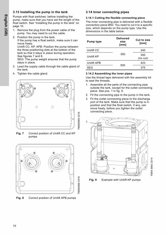
3.13 Installing the pump in the tank
Pumps with float switches: before installing the pump, make sure that you have set the length of the float switch. See “Installing the pump in the tank” on page 10.
1. Remove the plug from the power cable of the pump. You may need to cut the cable.
2. Position the pump in the tank.If the pump has a float switch, make sure it can move freely.Unilift CC, KP, APB: Position the pump between the three positioning dots at the bottom of the tank so that it stays in place during operation. See figures 7 and 8.SEG: The pump weight ensures that the pump stays in place.
3. Lead the supply cable through the cable gland of the tank.
4. Tighten the cable gland.
Fig. 7 Correct position of Unilift CC and KP pumps
Fig. 8 Correct position of Unilift APB pumps
3.14 Inner connecting pipes
3.14.1 Cutting the flexible connecting piece
The inner connecting pipe is delivered with a flexible connection piece Ø50. You need to cut it to a specific size, which depends on the pump type. Use the dimensions in the table below:
3.14.2 Assembling the inner pipes
Use the thread tape delivered with the assembly kit to seal the threads.
1. Assemble all the parts of the connecting pipe outside the tank, except for the outlet connecting piece. See pos. 1 in fig. 9.
2. Fit the connecting pipe to the pump in the tank.
3. Fit the outlet connecting piece to the discharge port of the tank. Make sure that the pump is in position and that the float switch, if any, can move freely, before you tighten the outlet connecting piece.
Fig. 9 Example with Unilift KP pumps
TM
06
59
65
03
16
TM
06
59
66
03
16
Pump typeDelivered
size[mm]
Cut to size [mm]
Unilift CC
350
240
Unilift KP350
(no cut)
Unilift APB500
423
SEG 375
TM
04
95
63
20
14
1
En
glis
h (
GB
)
11
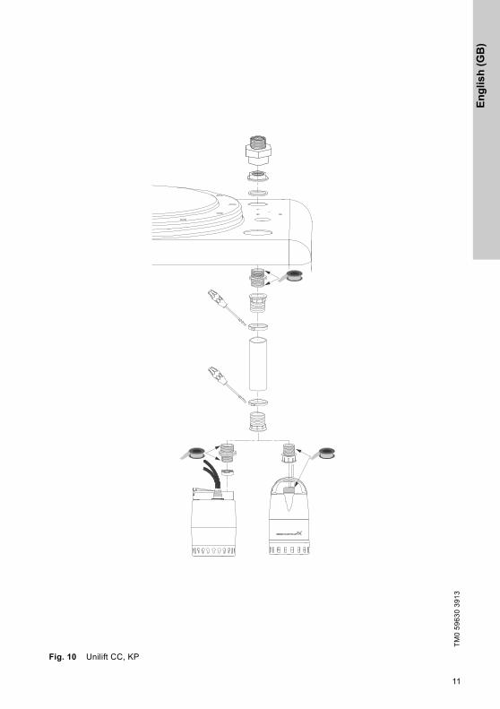
Fig. 10 Unilift CC, KP
TM
0 5
96
30
39
13
En
glish
(GB
)
12
TM
0 5
96
33
39
13
TM
0 5
96
32
39
13
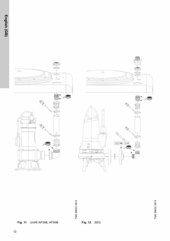
Fig. 11 Unilift AP35B, AP50B Fig. 12 SEG
x4
En
glis
h (
GB
)
13
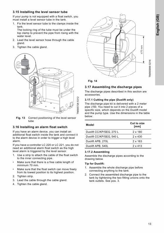
3.15 Installing the level sensor tube
If your pump is not equipped with a float switch, you must install a level sensor tube in the tank.
1. Fix the level sensor tube to the clamps inside the tank.The locking ring of the tube must be under the top clamp to prevent the pipe from rising with the water level.
2. Lead the level sensor hose through the cable gland.
3. Tighten the cable gland.
Fig. 13 Correct positioning of the level sensor tube
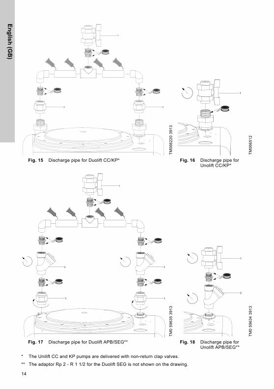
3.16 Installing an alarm float switch
If you have an alarm device, you can install an additional float switch inside the tank and connect it to the alarm device in order to trigger a high level alarm.
If you have a controller LC 220 or LC 221, you do not need an additional alarm float switch as the high level alarm is triggered by the level sensor.
1. Use a strip to attach the cable of the float switch to the inner connecting pipe.
• Make sure that there is a free cable length of minimum 70 mm.
• Make sure that the float switch can move freely from its lowest position to its highest position.
2. Tighten strip.
3. Lead the cable through the cable gland.
4. Tighten the cable gland.
Fig. 14
3.17 Assembling the discharge pipes
The discharge pipes described in this section are accessories.
3.17.1 Cutting the pipe (Duolift only)
The discharge pipe kit is delivered with a 2 meter pipe ∅50. You need to cut it into 2 pieces of a specific size, which depends on the Duolift model and the pump type. Use the dimensions in the table below:
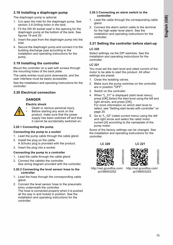
3.17.2 Assembling
Assemble the discharge pipes according to the drawing below.
Tip for Duolift:
1. Assemble the whole discharge pipe before connecting anything to the tank.
2. Connect the assembled discharge pipe to the tank by tightening the two fitting unions onto the tank outlets. See pos. 3.
TM
06
57
28
53
12
TM
06
58
99
02
16
ModelCut to size
[mm]
Duolift CC/KP/SEG, 270 L 2 x 180
Duolift CC/KP/SEG, 540 L 2 x 430
Duolift APB, 270L 2 x 163
Duolift APB, 540L 2 x 413
En
glish
(GB
)
14
* The Unilift CC and KP pumps are delivered with non-return clap valves.
** The adaptor Rp 2 - R 1 1/2 for the Duolift SEG is not shown on the drawing.
TM
06
62
20
39
13
TM
06
65
12
Fig. 15 Discharge pipe for Duolift CC/KP* Fig. 16 Discharge pipe for Unolift CC/KP*
TM
0 5
96
35
39
13
TM
0 5
96
34
39
13
Fig. 17 Discharge pipe for Duolift APB/SEG** Fig. 18 Discharge pipe for Unolift APB/SEG**
1
33
1
1
2
33
2
1
2
En
glis
h (
GB
)
15
3.18 Installing a diaphragm pump
The diaphragm pump is optional.
1. Cut open the inlet for the diaphragm pump. See section 3.8 Drilling holes in the tank.
2. Fit the DN 40 socket seal in the opening for the diaphragm pump at the bottom of the tank. See figures 19 and 20.
3. Insert the pipe from the diaphragm pump into the inlet.
4. Secure the diaphragm pump and connect it to the building discharge pipe according to the installation and operating instructions for the pump.
3.19 Installing the controller
Mount the controller on a wall with screws through the mounting holes of the back plate.
The cable entries must point downwards, and the user interface must be easily accessible.
See the installation and operating instructions for the controller.
3.20 Electrical connection
3.20.1 Connecting the pump
Connecting the pump to a socket
1. Lead the pump cable through the cable gland.
2. Install the plug on the cable. A Schuko plug is provided with the product.
3. Insert the plug into a socket.
Connecting the pump to a controller
1. Lead the cable through the cable gland.
2. Connect the cableto the controller.See wiring diagram provided with the controller.
3.20.2 Connecting the level sensor hose to the controller
1. Lead the hose through the corresponding cable gland.
2. Connect the level sensor hose to the pneumatic entry underneath the controller. The hose is connected properly when it is pushed all the way in and locked in position. See the installation and operating instructions for the controller.
3.20.3 Connecting an alarm switch to the controller
1. Lead the cable through the corresponding cable gland.
2. Connect the alarm switch cable to the terminal for the high-water level alarm. See the installation and operating instructions for the controller.
3.21 Setting the controller before start-up
LC 220
Select settings via the DIP switches. See the installation and operating instructions for the controller.
LC 221
You must set the start level and rated current of the motor to be able to start the product. All other settings are preset.
1. Close the isolating valves.
2. Make sure the pump switches on the controller are in position "OFF".
3. Switch on the controller.
4. When "L_01" is displayed (start level menu), press [OK].Select the start level using the left and right arrows, and press [OK].For more information on which start level to select, see “Setting start levels with controller” on page 20.
5. Go to "L_02" (rated current menu) using the left and right arrow and select the rated motor current [A] according to the nameplate of the pump motor.
Some of the factory settings can be changed. See the installation and operating instructions for the controller.
DANGER
Electric shock• Death or serious personal injury.• Before starting any work on the
product, make sure that the power supply has been switched off and that it cannot be accidentally switched on.
LC 220 LC 221
QR
98
50
32
52
QR
98
50
32
53
http://net.grundfos.com/qr/i/98503252
http://net.grundfos.com/qr/i/98503253
En
glish
(GB
)
16
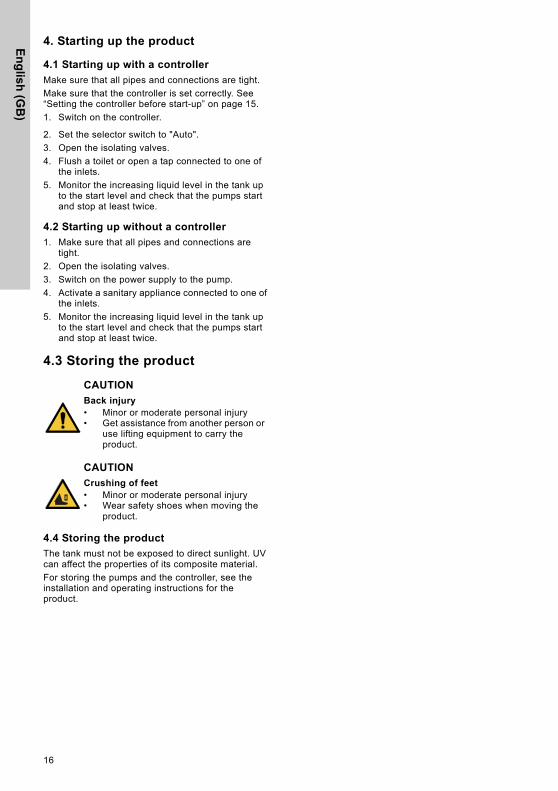
4. Starting up the product
4.1 Starting up with a controller
Make sure that all pipes and connections are tight.
Make sure that the controller is set correctly. See “Setting the controller before start-up” on page 15.
1. Switch on the controller.
2. Set the selector switch to "Auto".
3. Open the isolating valves.
4. Flush a toilet or open a tap connected to one of the inlets.
5. Monitor the increasing liquid level in the tank up to the start level and check that the pumps start and stop at least twice.
4.2 Starting up without a controller
1. Make sure that all pipes and connections are tight.
2. Open the isolating valves.
3. Switch on the power supply to the pump.
4. Activate a sanitary appliance connected to one of the inlets.
5. Monitor the increasing liquid level in the tank up to the start level and check that the pumps start and stop at least twice.
4.3 Storing the product
4.4 Storing the product
The tank must not be exposed to direct sunlight. UV can affect the properties of its composite material.
For storing the pumps and the controller, see the installation and operating instructions for the product.
CAUTION
Back injury• Minor or moderate personal injury• Get assistance from another person or
use lifting equipment to carry the product.
CAUTION
Crushing of feet• Minor or moderate personal injury• Wear safety shoes when moving the
product.
En
glis
h (
GB
)
17
5. Product introduction
5.1 Product overview
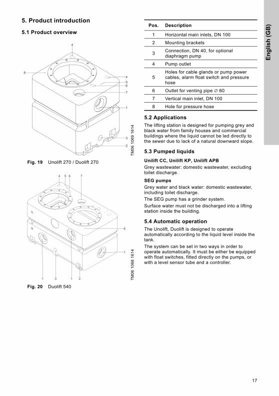
Fig. 19 Unolift 270 / Duolift 270
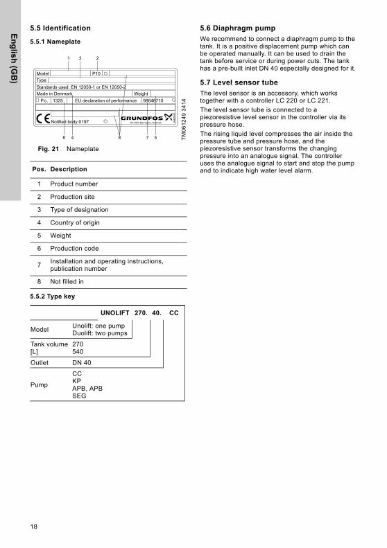
Fig. 20 Duolift 540
5.2 Applications
The lifting station is designed for pumping grey and black water from family houses and commercial buildings where the liquid cannot be led directly to the sewer due to lack of a natural downward slope.
5.3 Pumped liquids
Unilift CC, Unilift KP, Unilift APB
Grey wastewater: domestic wastewater, excluding toilet discharge.
SEG pumps
Grey water and black water: domestic wastewater, including toilet discharge.
The SEG pump has a grinder system.
Surface water must not be discharged into a lifting station inside the building.
5.4 Automatic operation
The Unolift, Duolift is designed to operate automatically according to the liquid level inside the tank.
The system can be set in two ways in order to operate automatically. It must be either be equipped with float switches, fitted directly on the pumps, or with a level sensor tube and a controller.
TM
06
10
69
16
14
TM
06
10
68
16
14
Pos. Description
1 Horizontal main inlets, DN 100
2 Mounting brackets
3Connection, DN 40, for optional diaphragm pump
4 Pump outlet
5Holes for cable glands or pump power cables, alarm float switch and pressure hose
6 Outlet for venting pipe ∅ 60
7 Vertical main inlet, DN 100
8 Hole for pressure hose
En
glish
(GB
)
18
5.5 Identification
5.5.1 Nameplate
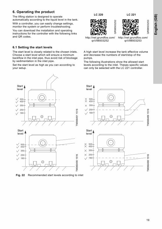
Fig. 21 Nameplate
5.5.2 Type key
5.6 Diaphragm pump
We recommend to connect a diaphragm pump to the tank. It is a positive displacement pump which can be operated manually. It can be used to drain the tank before service or during power cuts. The tank has a pre-built inlet DN 40 especially designed for it.
5.7 Level sensor tube
The level sensor is an accessory, which works together with a controller LC 220 or LC 221.
The level sensor tube is connected to a piezoresistive level sensor in the controller via its pressure hose.
The rising liquid level compresses the air inside the pressure tube and pressure hose, and the piezoresistive sensor transforms the changing pressure into an analogue signal. The controller uses the analogue signal to start and stop the pump and to indicate high water level alarm.
TM
06
12
49
34
14
Pos. Description
1 Product number
2 Production site
3 Type of designation
4 Country of origin
5 Weight
6 Production code
7Installation and operating instructions, publication number
8 Not filled in
UNOLIFT 270. 40. CC
ModelUnolift: one pumpDuolift: two pumps
Tank volume[L]
270540
Outlet DN 40
Pump
CCKPAPB, APBSEG
TypeStandards used: EN 12050-1 or EN 12050-2
Model
WeightP.c.
Made inEU declaration of performance
Denmark
P10
986467101325
Notified body:0197 DK-8850 Bjerringbro, Denmark 9849
5490
1 3 2
74 8 56
En
glis
h (
GB
)
19
6. Operating the productThe lifting station is designed to operate automatically according to the liquid level in the tank.
With a controller, you can easily change settings, monitor the system or perform troubleshooting.
You can download the installation and operating instructions for the controller with the following links and QR codes.
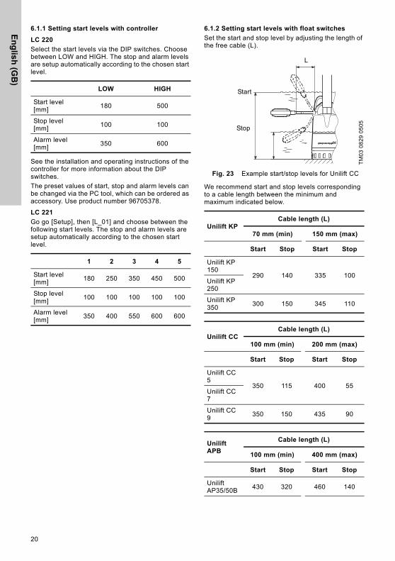
6.1 Setting the start levels
The start level is closely related to the chosen inlets. Choose a start level which will ensure a minimum backflow in the inlet pipe, thus avoid risk of blockage by sedimentation in the inlet pipe.
Set the start level as high as you can according to your setup.
A high start level increase the tank effective volume and decrease the numbers of start/stop of the pumps.
The following illustrations show the allowed start levels according to the inlet. Theses specific values can only be selected with the LC 221 controller.
Fig. 22 Recommended start levels according to inlet
LC 220 LC 221
QR
98
50
32
52
QR
98
50
32
53
http://net.grundfos.com/qr/i/98503252
http://net.grundfos.com/qr/i/98503253
TM
06
64
91
15
16
TM
06
64
89
15
16
TM
06
64
90
15
16
TM
06
64
88
15
16
180
350
450
250
500
Startlevel
180
350
450
250
500
Startlevel
180
350
450
250
500
Startlevel
180
350
450
250
500
Startlevel
En
glish
(GB
)
20
6.1.1 Setting start levels with controller
LC 220
Select the start levels via the DIP switches. Choose between LOW and HIGH. The stop and alarm levels are setup automatically according to the chosen start level.
See the installation and operating instructions of the controller for more information about the DIP switches.
The preset values of start, stop and alarm levels can be changed via the PC tool, which can be ordered as accessory. Use product number 96705378.
LC 221
Go go [Setup], then [L_01] and choose between the following start levels. The stop and alarm levels are setup automatically according to the chosen start level.
6.1.2 Setting start levels with float switches
Set the start and stop level by adjusting the length of the free cable (L).
Fig. 23 Example start/stop levels for Unilift CC
We recommend start and stop levels corresponding to a cable length between the minimum and maximum indicated below.
LOW HIGH
Start level [mm]
180 500
Stop level [mm]
100 100
Alarm level [mm]
350 600
1 2 3 4 5
Start level [mm]
180 250 350 450 500
Stop level [mm]
100 100 100 100 100
Alarm level [mm]
350 400 550 600 600
TM
03
08
29
05
05
Unilift KPCable length (L)
70 mm (min) 150 mm (max)
Start Stop Start Stop
Unilift KP 150
290 140 335 100Unilift KP 250
Unilift KP 350
300 150 345 110
Unilift CCCable length (L)
100 mm (min) 200 mm (max)
Start Stop Start Stop
Unilift CC 5
350 115 400 55Unilift CC 7
Unilift CC 9
350 150 435 90
Unilift APB
Cable length (L)
100 mm (min) 400 mm (max)
Start Stop Start Stop
Unilift AP35/50B
430 320 460 140
Start
Stop
L
En
glis
h (
GB
)
21
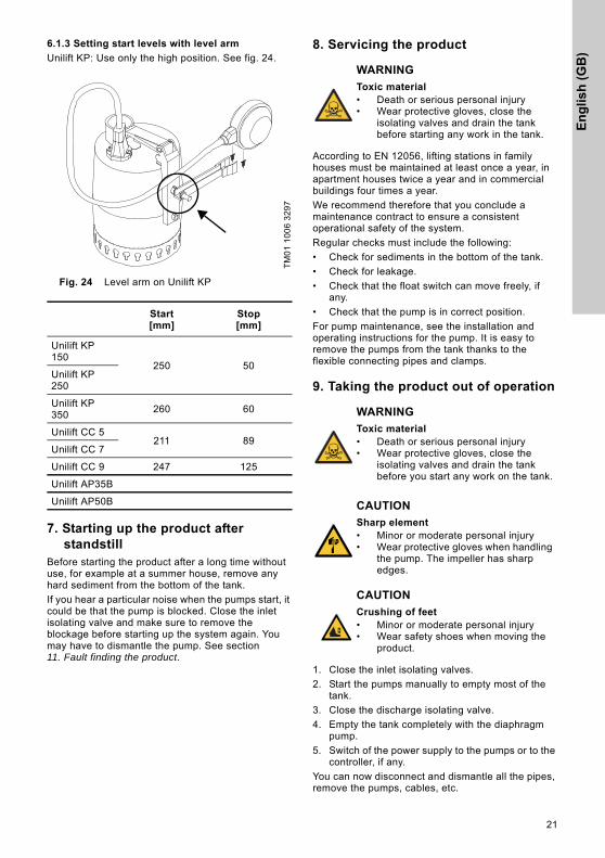
6.1.3 Setting start levels with level arm
Unilift KP: Use only the high position. See fig. 24.
Fig. 24 Level arm on Unilift KP
7. Starting up the product after standstill
Before starting the product after a long time without use, for example at a summer house, remove any hard sediment from the bottom of the tank.
If you hear a particular noise when the pumps start, it could be that the pump is blocked. Close the inlet isolating valve and make sure to remove the blockage before starting up the system again. You may have to dismantle the pump. See section 11. Fault finding the product.
8. Servicing the product
According to EN 12056, lifting stations in family houses must be maintained at least once a year, in apartment houses twice a year and in commercial buildings four times a year.
We recommend therefore that you conclude a maintenance contract to ensure a consistent operational safety of the system.
Regular checks must include the following:
• Check for sediments in the bottom of the tank.
• Check for leakage.
• Check that the float switch can move freely, if any.
• Check that the pump is in correct position.
For pump maintenance, see the installation and operating instructions for the pump. It is easy to remove the pumps from the tank thanks to the flexible connecting pipes and clamps.
9. Taking the product out of operation
1. Close the inlet isolating valves.
2. Start the pumps manually to empty most of the tank.
3. Close the discharge isolating valve.
4. Empty the tank completely with the diaphragm pump.
5. Switch of the power supply to the pumps or to the controller, if any.
You can now disconnect and dismantle all the pipes, remove the pumps, cables, etc.
TM
01
10
06
32
97
Start[mm]
Stop[mm]
Unilift KP 150
250 50Unilift KP 250
Unilift KP 350
260 60
Unilift CC 5211 89
Unilift CC 7
Unilift CC 9 247 125
Unilift AP35B
Unilift AP50B
WARNING
Toxic material• Death or serious personal injury• Wear protective gloves, close the
isolating valves and drain the tank before starting any work in the tank.
WARNING
Toxic material• Death or serious personal injury• Wear protective gloves, close the
isolating valves and drain the tank before you start any work on the tank.
CAUTION
Sharp element• Minor or moderate personal injury• Wear protective gloves when handling
the pump. The impeller has sharp edges.
CAUTION
Crushing of feet• Minor or moderate personal injury• Wear safety shoes when moving the
product.
En
glish
(GB
)
22
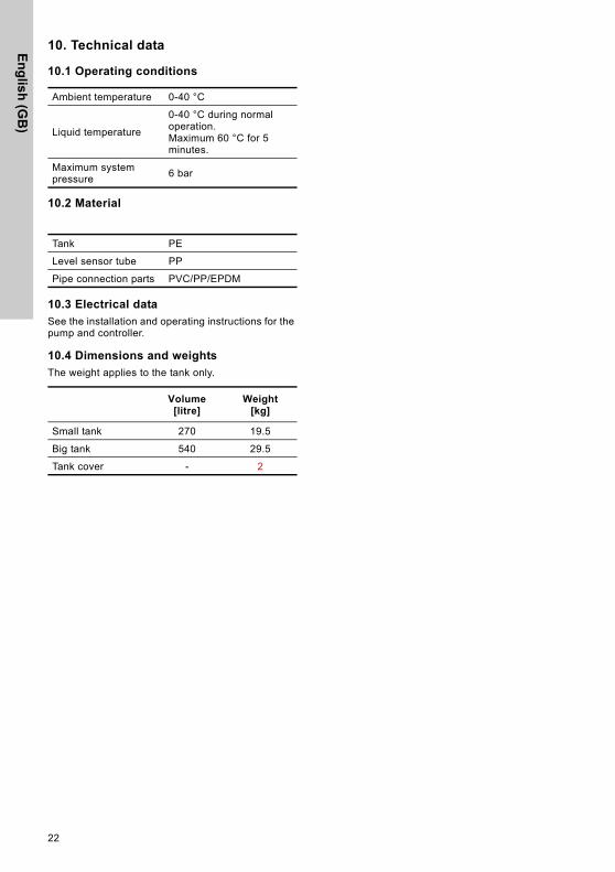
10. Technical data
10.1 Operating conditions
10.2 Material
10.3 Electrical data
See the installation and operating instructions for the pump and controller.
10.4 Dimensions and weights
The weight applies to the tank only.
Ambient temperature 0-40 °C
Liquid temperature
0-40 °C during normal operation.Maximum 60 °C for 5 minutes.
Maximum system pressure
6 bar
Tank PE
Level sensor tube PP
Pipe connection parts PVC/PP/EPDM
Volume[litre]
Weight[kg]
Small tank 270 19.5
Big tank 540 29.5
Tank cover - 2
En
glis
h (
GB
)
23
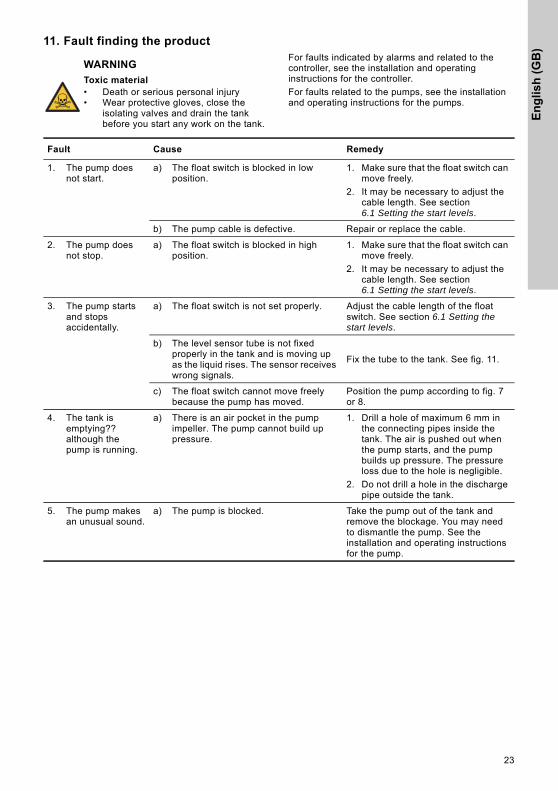
11. Fault finding the productFor faults indicated by alarms and related to the controller, see the installation and operating instructions for the controller.
For faults related to the pumps, see the installation and operating instructions for the pumps.
WARNING
Toxic material• Death or serious personal injury• Wear protective gloves, close the
isolating valves and drain the tank before you start any work on the tank.
Fault Cause Remedy
1. The pump does not start.
a) The float switch is blocked in low position.
1. Make sure that the float switch can move freely.
2. It may be necessary to adjust the cable length. See section 6.1 Setting the start levels.
b) The pump cable is defective. Repair or replace the cable.
2. The pump does not stop.
a) The float switch is blocked in high position.
1. Make sure that the float switch can move freely.
2. It may be necessary to adjust the cable length. See section 6.1 Setting the start levels.
3. The pump starts and stops accidentally.
a) The float switch is not set properly. Adjust the cable length of the float switch. See section 6.1 Setting the start levels.
b) The level sensor tube is not fixed properly in the tank and is moving up as the liquid rises. The sensor receives wrong signals.
Fix the tube to the tank. See fig. 11.
c) The float switch cannot move freely because the pump has moved.
Position the pump according to fig. 7 or 8.
4. The tank is emptying?? although the pump is running.
a) There is an air pocket in the pump impeller. The pump cannot build up pressure.
1. Drill a hole of maximum 6 mm in the connecting pipes inside the tank. The air is pushed out when the pump starts, and the pump builds up pressure. The pressure loss due to the hole is negligible.
2. Do not drill a hole in the discharge pipe outside the tank.
5. The pump makes an unusual sound.
a) The pump is blocked. Take the pump out of the tank and remove the blockage. You may need to dismantle the pump. See the installation and operating instructions for the pump.
En
glish
(GB
)
24
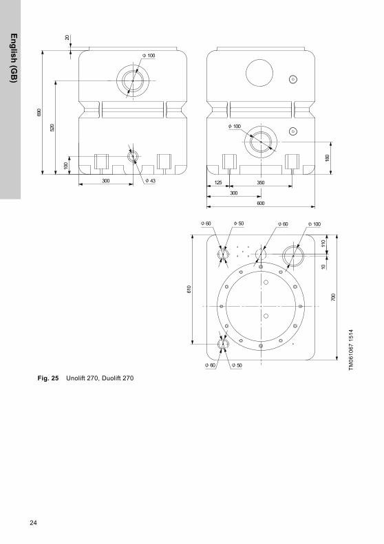
Fig. 25 Unolift 270, Duolift 270
TM
06
10
67
15
14
En
glis
h (
GB
)
25
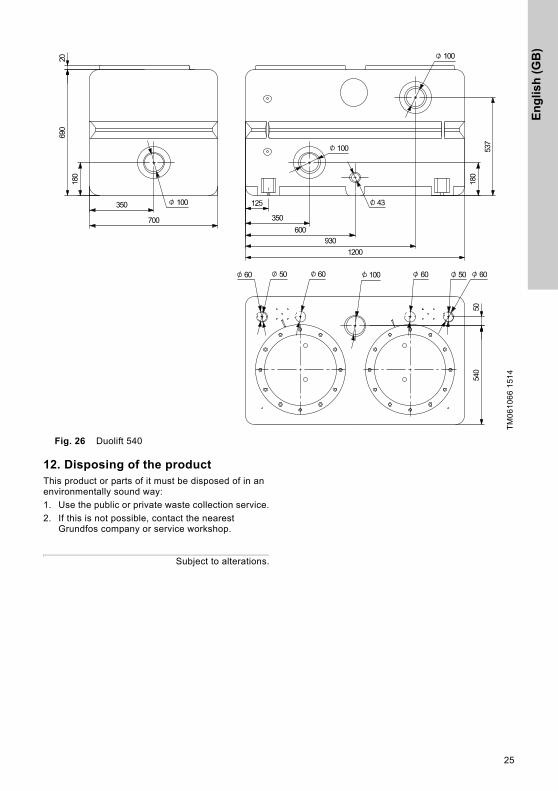
Fig. 26 Duolift 540
12. Disposing of the productThis product or parts of it must be disposed of in an environmentally sound way:
1. Use the public or private waste collection service.
2. If this is not possible, contact the nearest Grundfos company or service workshop.
Subject to alterations.
TM
06
10
66
15
14
De
cla
ratio
n o
f pe
rform
an
ce
Declaration of performance 1
GB:EC declaration of performance in accordance with Annex III of Regulation (EU) No 305/2011
(Construction Product Regulation)
1. Unique identification code of the product type: – EN 12050-1 or EN 12050-2.
2. Type, batch or serial number or any other element allowing identification of the construction product as required pursuant to Article 11(4):– Pumping stations marked with EN 12050-1 or EN 12050-2 on
the nameplate.3. Intended use or uses of the construction product, in accordance
with the applicable harmonised technical specification, as foreseen by the manufacturer: – Pumping stations for pumping of wastewater containing faecal
matter marked with EN 12050-1 on the nameplate.4. Name, registered trade name or registered trade mark and
contact address of the manufacturer as required pursuant to Article 11(5): – Grundfos Holding A/S
Poul Due Jensens Vej 78850 BjerringbroDenmark.
5. NOT RELEVANT.6. System or systems of assessment and verification of constancy
of performance of the construction product as set out in Annex V:
– System 3.7. In case of the declaration of performance concerning a
construction product covered by a harmonised standard:– TÜV Rheinland LGA Products GmbH, identification number:
0197.Performed test according to EN 12050-1 or EN 12050-2 under system 3.(description of the third party tasks as set out in Annex V)
– Certificate number: LGA-Certificate No 7310150. Type-tested and monitored.
8. NOT RELEVANT.9. Declared performance:
The products covered by this declaration of performance are in compliance with the essential characteristics and the performance requirements as described in the following:– Standards used: EN 12050-1 or EN 12050-2:2001.
10. The performance of the product identified in points 1 and 2 is in conformity with the declared performance in point 9.
CZ:Prohlášení o vlastnostech ES v souladu s
Dodatkem III předpisu (EU) č. 305/2011(Předpis pro stavební výrobky)
1. Jedinečný identifikační kód typu výrobku:– EN 12050-1 nebo EN 12050-2.
2. Typ, dávka nebo výrobní číslo nebo jakýkoliv prvek umožňující identifikaci stavebního výrobku podle požadavku Článku 11(4):– Čerpací stanice odpadních vod s označením EN 12050-1 nebo
EN 12050-2 na typovém štítku.3. Zamýšlená použití stavebního výrobku v souladu s příslušnou
harmonizovanou technickou specifikací výrobce:– Čerpací stanice odpadních vod s fekáliemi s označením EN
12050-1 na typovém štítku.4. Název, registrovaný obchodní název nebo registrovaná ochranná
známka a kontaktní adresa výrobce podle požadavku Článku 11(5):– Grundfos Holding A/S
Poul Due Jensens Vej 78850 BjerringbroDánsko.
5. NESOUVISÍ.6. Systém nebo systémy posuzování a ověřování stálosti vlastností
stavebního výrobku podle ustanovení Dodatku V:– Systém 3.
7. V případě prohlášení o vlastnostech stavebního výrobku zahrnutého v harmonizované normě:– TÜV Rheinland LGA Products GmbH, identifikační číslo: 0197.
Proveden test podle EN 12050-1 nebo EN 12050-2 v systému 3.(popis úkolů třetí strany podle ustanovení Dodatku V)
– Číslo certifikátu: Certifikát LGA č. 7310150. Typ testován a monitorován.
8. NESOUVISÍ.9. Prohlašované vlastnosti:
Výrobky uvedené v tomto Prohlášení o vlastnostech jsou v souladu se základními charakteristikami a požadavky na vlastnosti, jak je popsáno níže:– Použité normy: EN 12050-1 nebo EN 12050-2:2001.
10. Vlastnosti výrobku uvedeného v bodech 1 a 2 v souladu s prohlašovanými vlastnostmi v bodě 9.
26
De
cla
rati
on
of
pe
rfo
rma
nc
e
DK:EU-ydeevnedeklaration i henhold til bilag III afforordning (EU) nr. 305/2011(Byggevareforordningen)
1. Varetypens unikke identifikationskode:– EN 12050-1 eller EN 12050-2.
2. Type-, parti- eller serienummer eller en anden form for angivelse ved hjælp af hvilken byggevaren kan identificeres som krævet i henhold til artikel 11, stk. 4:– Pumpestationer der er mærket med EN 12050-1 eller EN
12050-2 på typeskiltet.3. Byggevarens tilsigtede anvendelse eller anvendelser i
overensstemmelse med den gældende harmoniserede tekniske specifikation som påtænkt af fabrikanten:– Pumpestationer til pumpning af spildevand med fækalier der er
mærket med EN 12050-1 på typeskiltet.4. Fabrikantens navn, registrerede firmabetegnelse eller
registrerede varemærke og kontaktadresse som krævet i henhold til artikel 11, stk. 5:– Grundfos Holding A/S
Poul Due Jensens Vej 78850 BjerringbroDanmark.
5. IKKE RELEVANT.6. Systemet eller systemerne til vurdering og kontrol af at byggeva-
rens ydeevne er konstant, jf. bilag V:– System 3.
7. Hvis ydeevnedeklarationen vedrører en byggevare der er omfattet af en harmoniseret standard:– TÜV Rheinland LGA Products GmbH, identifikationsnummer:
0197.Udført test i henhold til EN 12050-1 eller EN 12050-2 efter system 3(beskrivelse af tredjepartsopgaverne, jf. bilag V).
– Certifikatnummer: LGA-certifikat nr. 7310150. Typetestet og overvåget.
8. IKKE RELEVANT.9. Deklareret ydeevne:
De produkter der er omfattet af denne ydeevnedeklaration, er i overensstemmelse med de væsentlige egenskaber og ydelseskrav der er beskrevet i følgende:– Anvendte standarder: EN 12050-1 eller EN 12050-2:2001.
10. Ydeevnen for den byggevare der er anført i punkt 1 og 2, er i overensstemmelse med den deklarerede ydeevne i punkt 9.
DE:EG-Leistungserklärung gemäß Anhang III der
Verordnung (EU) Nr. 305/2011(Bauprodukte-Verordnung)
1. Einmalige Kennnummer des Produkttyps:– EN 12050-1 oder EN 12050-2.
2. Typ, Charge, Seriennummer oder jedes andere Element, das eine Identifizierung des Bauprodukts erlaubt, wie in Artikel 11 (4) vorgeschrieben.– Pumpstationen, auf dem Typenschild mit EN 12050-1 oder EN
12050-2 gekennzeichnet.3. Verwendungszweck oder Verwendungszwecke des Bauprodukts,
gemäß den geltenden harmonisierten technischen Spezifikationen, wie vom Hersteller vorgesehen:– Pumpstationen für die Förderung von fäkalienhaltigem
Abwasser, auf dem Typenschild mit EN 12050-1 gekennzeichnet.
4. es Warenzeichen und Kontaktanschrift des Herstellers, wie in Artikel 11(5) vorgeschrieben.– Grundfos Holding A/S
Poul Due Jensens Vej 78850 BjerringbroDänemark
5. NICHT RELEVANT.6. System oder Systeme zur Bewertung und Überprüfung der
Leistungsbeständigkeit des Bauprodukts gemäß Anhang V: – System 3.
7. Bei der Leistungserklärung bezüglich eines von einer harmonisierten Norm erfassten Bauprodukts:– TÜV Rheinland LGA Products GmbH, Kennnummer: 0197.
Vorgenommene Prüfung gemäß EN 12050-1 oder EN 12050-2 unter Anwendung von System 3.(Beschreibung der Aufgaben von unabhängigen Dritten gemäß Anhang V)
– Zertifikatnummer: LGA-Zertifikatnr. 7310150. Typgeprüft und überwacht.
8. NICHT RELEVANT.9. Erklärte Leistung:
Die von dieser Leistungserklärung erfassten Produkte entsprechen den grundlegenden Charakteristika und Leistungsanforderungen, wie im Folgenden beschrieben:– Angewendete Normen: EN 12050-1 oder EN 12050-2:2001.
10. Die Leistung des in Punkt 1 und 2 genannten Produkts entspricht der in Punkt 9 erklärten Leistung.
27
De
cla
ratio
n o
f pe
rform
an
ce
ES:Declaración CE de prestaciones conforme al Anexo III del Reglamento (EU) n.° 305/2011
(Reglamento de productos de construcción)
1. Código de identificación único del tipo de producto:– EN 12050-1 o EN 12050-2.
2. Tipo, lote o número de serie, o cualquier otro elemento que facilite la identificación del producto de construcción de acuerdo con los requisitos establecidos en el Artículo 11(4):– Estaciones de bombeo en cuya placa de características
figuren las normas EN 12050-1 o EN 12050-2.3. Uso o usos previstos del producto de construcción, conforme a la
especificación técnica armonizada correspondiente, según lo previsto por el fabricante:– Estaciones de bombeo para el bombeo de aguas residuales
que contengan materia fecal en cuya placa de características figure la norma EN 12050-1..
4. Nombre, nombre comercial registrado o marca comercial registrada y domicilio de contacto del fabricante de acuerdo con los requisitos establecidos en el Artículo 11(5):– Grundfos Holding A/S
Poul Due Jensens Vej 78850 BjerringbroDinamarca.
5. NO CORRESPONDE.6. Sistema o sistemas de evaluación y verificación de la
continuidad de las prestaciones del producto de construcción, de acuerdo con lo establecido en el Anexo V.– Sistema 3.
7. Si la declaración de prestaciones concierne a un producto de construcción cubierto por una norma armonizada:– TÜV Rheinland LGA Products GmbH, número de
identificación: 0197.Ensayo ejecutado según las normas EN 12050-1 o EN 12050-2, sistema 3.(Descripción de las tareas de las que deben responsabilizarse otras partes de acuerdo con lo establecido en el Anexo V).
– Número de certificado: Certificado LGA n.º 7310150. Tipo sometido a ensayo y monitorizado.
8. NO CORRESPONDE.9. Prestaciones declaradas:
Los productos que cubre esta declaración de prestaciones satisfacen las características fundamentales y requisitos en materia de prestaciones descritos en:– Normas aplicadas: EN 12050-1 o EN 12050-2:2001.
10. Las prestaciones del producto indicado en los puntos 1 y 2 cumplen lo declarado en el punto 9.
FR:Déclaration des performances CE
conformément à l'Annexe III du Règlement (UE) n° 305/2011
(Règlement Produits de Construction)
1. Code d'identification unique du type de produit :– EN 12050-1 ou EN 12050-2.
2. Numéro de type, de lot ou de série ou tout autre élément permet-tant l'identification du produit de construction comme l'exige l'Article 11(4) :– Stations de pompage marquées EN 12050-1 ou EN 12050-2
sur la plaque signalétique.3. Usage(s) prévu(s) du produit de construction conformément à la
spécification technique harmonisée applicable comme indiqué par le fabricant :– Stations de pompage pour le pompage des effluents contenant
des matières fécales marquées EN 12050-1 sur la plaque signalétique.
4. Nom, nom de commerce déposé ou marque commerciale déposée et adresse du fabricant comme l'exige l'Article 11(5) :– Grundfos Holding A/S
Poul Due Jensens Vej 78850 BjerringbroDanemark.
5. NON APPLICABLE.6. Système ou systèmes d'attestation et de vérification de la
constance des performances du produit de construction comme stipulé dans l'Annexe V :– Système 3.
7. En cas de déclaration des performances d'un produit de construction couvert par une norme harmonisée :– TÜV Rheinland LGA Products GmbH, numéro d'identification :
0197.Test effectué conformément aux normes EN 12050-1 ou EN 12050-2 selon le système 3.(description des tâches de tierce partie comme stipulé dans l'Annexe V)
– Numéro de certificat : Certificat LGA n° 7310150. Contrôlé et homologué.
8. NON APPLICABLE.9. Performances déclarées :
Les produits couverts par cette déclaration des performances sont conformes aux caractéristiques essentielles et aux exigences de performances décrites par la suite :– Normes utilisées : EN 12050-1 ou EN 12050-2:2001.
10. Les performances du produit identifié aux points 1 et 2 sont conformes aux performances déclarées au point 9.
28
De
cla
rati
on
of
pe
rfo
rma
nc
e
IT:Dichiarazione CE di prestazioni in conformitàall'all. III del Regolamento (UE) n. 305/2011(regolamento sui prodotti da costruzione)
1. Codice identificativo esclusivo del tipo di prodotto:– EN 12050-1 oppure EN 12050-2.
2. Tipo, lotto o numero di serie o qualsiasi altro elemento che consenta l'identificazione del prodotto da costruzione come necessario secondo l'art. 11(4):– Stazioni di pompaggio, marcate con EN 12050-1 oppure EN
12050-2 sulla targa dei dati identificativi.3. Utilizzo o utilizzi previsti del prodotto da costruzione, in accordo
alla specifica tecnica armonizzata pertinente, come previsto dal fabbricante:– Stazioni di pompaggio di acque reflue contenenti materiali
fecali, marcate con EN 12050-1 sulla targa dei dati identificativi.
4. Denominazione, denominazione commerciale registrata o marchio registrato e indirizzo di contatto del fabbricante secondo l'art. 11(5):– Grundfos Holding A/S
Poul Due Jensens Vej 78850 BjerringbroDanimarca.
5. NON RILEVANTE.6. Sistema o sistemi di valutazione e verifica della costanza delle
prestazioni del prodotto da costruzione come definito sub all. V:– Sistema 3.
7. In caso di dichiarazione di prestazioni concernente un prodotto da costruzione conforme a una norma armonizzata:– TÜV Rheinland LGA Products GmbH, numero
d'identificazione: 0197.Test eseguito secondo EN 12050-1 oppure EN 12050-2 con il sistema 3.(descrizione delle mansioni di terzi come definito sub all. V)
– Numero certificato: N. certificato LGA 7310150. Testato per il tipo e monitorato.
8. NON RILEVANTE.9. Prestazioni dichiarate:
I prodotti coperti dalla presente dichiarazione di prestazione sono conformi alle caratteristiche essenziali ed ai requisiti di prestazioni descritti dove segue:– Norme applicate: EN 12050-1 oppure EN 12050-2:2001.
10. Le prestazioni del prodotto identificato ai punti 1 e 2 sono conformi alle prestazioni dichiarate al punto 9.
NL:Prestatieverklaring van EC in overeenstemming
met Bijlage III van verordening (EU) nr. 305/2011
(Bouwproductenverordening)
1. Unieke identificatiecode van het producttype:– EN 12050-1 of EN 12050-2.
2. Type-, batch- of serienummer of enig ander element dat identificatie van het bouwproduct mogelijk maakt zoals vereist conform artikel 11(4):– Pompstations gemarkeerd met EN 12050-1 of EN 12050-2 op
het typeplaatje.3. Beoogde toepassing of toepassingen van het bouwproduct, in
overeenstemming met de van toepassing zijnde geharmoniseerde technische specificatie, zoals voorzien door de fabrikant:– Pompstations voor het verpompen van afvalwater dat fecale
materie bevat gemarkeerd met EN 12050-1 op het typeplaatje.4. Naam, gedeponeerde handelsnaam of gedeponeerd
handelsmerk en contactadres van de fabrikant zoals vereist conform artikel 11(5):– Grundfos Holding A/S
Poul Due Jensens Vej 78850 BjerringbroDenemarken.
5. NIET RELEVANT.6. Systeem of systemen voor beoordeling en verificatie van
constantheid van prestaties van het bouwproduct zoals beschreven in Bijlage V:– Systeem 3.
7. In het geval van de prestatieverklaring voor een bouwproduct dat onder een geharmoniseerde norm valt:– TÜV Rheinland LGA Products GmbH, identificatienummer:
0197.Uitgevoerde test conform EN 12050-1 of EN 12050-2 onder systeem 3.(beschrijving van de externe taken zoals beschreven in Bijlage V)
– Certificaatnummer: LGA-certificaatnr. 7310150. Type getest en bewaakt.
8. NIET RELEVANT.9. Verklaarde prestatie:
De producten die vallen onder deze prestatieverklaring zijn in overeenstemming met de essentiële eigenschappen en de pres-tatievereisten zoals beschreven in het volgende:– Gebruikte normen: EN 12050-1 of EN 12050-2:2001.
10. De prestaties van het product dat is geïdentificeerd in punten 1 en 2 zijn in overeenstemming met de verklaarde prestaties in punt 9.
29
De
cla
ratio
n o
f pe
rform
an
ce
PL:Deklaracja właściwości użytkowych WE według
załącznika III do dyrektywy (UE) nr 305/2011 w/s wprowadzania do obrotu wyrobów
budowlanych
1. Niepowtarzalny kod identyfikacyjny typu wyrobu:– EN 12050-1 lub EN 12050-2.
2. Numer typu, partii lub serii lub jakikolwiek inny element umożliwiający identyfikację wyrobu budowlanego, wymagany zgodnie z art. 11 ust. 4:– Przepompownie oznaczone na tabliczce znamionowej kodem
EN 12050-1 lub EN 12050-2.3. Przewidziane przez producenta zamierzone zastosowanie lub
zastosowania wyrobu budowlanego zgodnie z mającą zastosowanie zharmonizowaną specyfikacją techniczną:– Przepompownie do pompowania ścieków zawierających
fekalia, oznaczone na tabliczce znamionowej kodem EN 12050-1.
4. Nazwa, zastrzeżona nazwa handlowa lub zastrzeżony znak towarowy oraz adres kontaktowy producenta, wymagany zgodnie z art. 11 ust. 5:– Grundfos Holding A/S
Poul Due Jensens Vej 78850 BjerringbroDania.
5. NIE DOTYCZY.6. System lub systemy oceny i weryfikacji stałości właściwości
użytkowych wyrobu budowlanego określone w załączniku V:– System 3.
7. W przypadku deklaracji właściwości użytkowych dotyczącej wyrobu budowlanego objętego normą zharmonizowaną:– Jednostka certyfikująca TÜV Rheinland LGA Products GmbH,
numer identyfikacyjny: 0197.przeprowadziła badanie określone w EN 12050-1 lub EN 12050-2, w systemie 3 i wydała certyfikat(opis zadań strony trzeciej, określonych w załączniku V)
– Nr certyfikatu: certyfikat LGA nr 7310150 (certyfikat badania typu i stałości właściwości użytkowych).
8. NIE DOTYCZY.9. Deklarowane właściwości użytkowe:
Wyroby, których dotyczy niniejsza deklaracja właściwości użytkowych są zgodne z zasadniczymi charakterystykami i wymaganiami określonymi w następujących normach: – Zastosowane normy: EN 12050-1 lub EN 12050-2:2001.
10. Właściwości użytkowe wyrobu określone w pkt 1 i 2 są zgodne z właściwościami użytkowymi deklarowanymi w pkt 9.
PT:Declaração de desempenho CE, em
conformidade com o Anexo III do Regulamento (UE) N.° 305/2011
(Regulamento de Produtos da Construção)
1. Código de identificação exclusivo do tipo de produto:– EN 12050-1 ou EN 12050-2.
2. Tipo, lote ou número de série ou qualquer outro elemento que permita a identificação do produto de construção, em conformidade com o Artigo 11(4):– Estações de bombeamento com a indicação EN 12050-1 ou
EN 12050-2 na chapa de características.3. Utilização ou utilizações prevista(s) do produto de construção,
em conformidade com a especificação técnica harmonizada aplicável, conforme previsto pelo fabricante:– Estações de bombeamento para bombeamento de águas
residuais com conteúdo de matéria fecal com a indicação EN 12050-1 na chapa de características.
4. Nome, nome comercial registado ou marca registada e endereço de contacto do fabricante, em conformidade com o Artigo 11(5):– Grundfos Holding A/S
Poul Due Jensens Vej 78850 BjerringbroDinamarca.
5. NÃO RELEVANTE.6. Sistema ou sistemas de avaliação e verificação da regularidade
do desempenho do produto de construção, conforme definido no Anexo V:– Sistema 3.
7. Em caso de declaração de desempenho referente a um produto de construção abrangido por uma norma harmonizada:– TÜV Rheinland LGA Products GmbH, número de identificação:
0197.Teste realizado em conformidade com EN 12050-1 ou EN 12050-2 ao abrigo do sistema 3.(descrição das tarefas de partes terceiras, conforme definido no Anexo V)
– Número do certificado: Certificado LGA N.º 7310150. Testado e monitorizado.
8. NÃO RELEVANTE.9. Desempenho declarado:
Os produtos abrangidos por esta declaração de desempenho cumprem as características essenciais e os requisitos de desempenho conforme descritos em:– Normas utilizadas: EN 12050-1 ou EN 12050-2:2001.
10. O desempenho do produto identificado nos pontos 1 e 2 encontra-se em conformidade com o desempenho declarado no ponto 9.
30
De
cla
rati
on
of
pe
rfo
rma
nc
e
RU:Декларация ЕС о рабочих характеристиках согласно Приложению III Регламента (ЕС) №305/2011(Регламент на конструкционные,
строительные материалы и продукцию)
1. Код однозначной идентификации типа продукции:– EN 12050-1 или EN 12050-2.
2. Тип, номер партии, серийный номер или любой другой параметр, обеспечивающий идентификацию строительного оборудования согласно Статье 11(4): – На фирменной табличке насосных установок указано обозначение EN 12050-1 или EN 12050-2.
3. Целевое применение или применения строительного оборудования в соответствии с применимыми согласованными техническими условиями, предусмотренными производителем:– Насосные установки для перекачки сточных вод с фекалиями имеют обозначение EN 12050-1 на фирменной табличке.
4. Название, зарегистрированное торговое имя или зарегистрированная торговая марта и контактный адрес производителя согласно Статье 11(5):– Grundfos Holding A/S
Poul Due Jensens Vej 78850 BjerringbroДания.
5. НЕ ИСПОЛЬЗУЕТСЯ.6. Система или системы оценки и проверки постоянства
рабочих характеристик строительного оборудования согласно Приложению V:– Система 3.
7. Если декларация о рабочих характеристиках касается строительного оборудования, предусмотренного согласованным стандартом: – TÜV Rheinland LGA Products GmbH, идентификационный номер: 0197.Испытание выполнено согласно EN 12050-1 или EN 12050-2 по системе 3.(описание задач третьей стороны согласно Приложению V)
– Номер сертификата: LGA-Сертификат № 7310150. Прошёл типовые испытания и контроль..
8. НЕ ИСПОЛЬЗУЕТСЯ.9. Заявленные технические характеристики:
Оборудование, подпадающее под настоящую декларацию о технических характеристиках, соответствует существенным характеристикам и требованиям к рабочим характеристикам, указанным ниже:– Применяемые стандарты: EN 12050-1 или EN 12050-
2:2001.10. Технические характеристики оборудования, указанные в
пунктах 1 и 2, соответствуют заявленным техническим характеристикам из пункта 9.
SK:Vyhlásenie o parametroch ES v súlade s prílohou III nariadenia (EÚ) č. 305/2011(Nariadenie o stavebných výrobkoch)
1. Jedinečný identifikačný kód typu výrobku:– EN 12050-1 alebo EN 12050-2.
2. Typ, číslo výrobnej dávky alebo sériové číslo, alebo akýkoľvek iný prvok umožňujúci identifikáciu stavebného výrobku, ako sa vyžaduje podľa článku 11 ods. 4:– Čerpacie stanice s označením EN 12050-1 alebo EN 12050-2
na typovom štítku.3. Zamýšľané použitia stavebného výrobku, ktoré uvádza výrobca,
v súlade s uplatniteľnou harmonizovanou technickou špecifikáciou:– Čerpacie stanice určené na čerpanie splaškov s obsahom
fekálií s označením EN 12050-1 na typovom štítku.4. Názov, registrovaný obchodný názov alebo registrovaná
obchodná značka a kontaktná adresa výrobcu podľa požiadaviek článku 11, ods. 5:– Grundfos Holding A/S
Poul Due Jensens Vej 78850 BjerringbroDánsko.
5. NEVZŤAHUJE SA.6. Systém alebo systémy posudzovania a overovania nemennosti
parametrov stavebného výrobku podľa ustanovení prílohy V:– Systém 3.
7. V prípade vyhlásenia o parametroch týkajúceho sa stavebného výrobku, na ktorý sa vzťahuje harmonizovaná norma:– TÜV Rheinland LGA Products GmbH, identifikačné číslo:
0197.Vykonal skúšku podľa EN 12050-1 alebo EN 12050-2 v systéme 3.(popis úloh tretej strany, ako sa uvádzajú v prílohe V)
– Číslo certifikátu: Certifikát LGA č. 7310150. Typovo skúšaný a monitorovaný.
8. NEVZŤAHUJE SA.9. Deklarované parametre:
Výrobky, na ktoré sa vzťahuje toto vyhlásenie o parametroch, vyhovujú podstatnými vlastnosťami a parametrami nasledovne:– Použité normy: EN 12050-1 alebo EN 12050-2:2001.
10. Parametre výrobku uvedené v bodoch 1 a 2 sú v zhode s deklarovanými parametrami v bode 9.
31
De
cla
ratio
n o
f pe
rform
an
ce
FI:EY-suoritustasoilmoitus laadittu asetuksen
305/2011/EU liitteen III mukaisesti(Rakennustuoteasetus)
1. Tuotetyypin yksilöllinen tunniste:– EN 12050-1 tai EN 12050-2.
2. Tyyppi-, erä- tai sarjanumero tai muu merkintä, jonka ansiosta rakennustuotteet voidaan tunnistaa, kuten 11 artiklan 4 kohdassa edellytetään:– Pumppaamot, joiden arvokilvessä on merkintä EN 12050-1 tai
EN 12050-2.3. Valmistajan ennakoima, sovellettavan yhdenmukaistetun
teknisen eritelmän mukainen rakennustuotteen aiottu käyttötarkoitus tai -tarkoitukset:– Pumppaamot ulosteperäistä materiaalia sisältävien jätevesien
pumppaukseen. Arvokilvessä on merkintä EN 12050-1.4. Valmistajan nimi, rekisteröity kauppanimi tai tavaramerkki sekä
osoite, josta valmistajaan saa yhteyden, kuten 11 artiklan 5 kohdassa edellytetään:– Grundfos Holding A/S
Poul Due Jensens Vej 78850 BjerringbroTanska.
5. EI TARVITA.6. Rakennustuotteen suoritustason pysyvyyden arviointi- ja
varmennusjärjestelmä(t) liitteen V mukaisesti:– Järjestelmä 3.
7. Kun kyse on yhdenmukaistetun standardin piiriin kuuluvan rakennustuotteen suoritustasoilmoituksesta:– TÜV Rheinland LGA Products GmbH, tunnistenumero: 0197.
Testaus suoritettu standardien EN 12050-1 tai EN 12050-2 ja järjestelmän 3 mukaisesti.(Liitteessä V esitettyjä kolmannen osapuolen tehtävien kuvauksia noudattaen.)
– Sertifikaatin numero: LGA-sertifikaatti nro 7310150. Tyyppitestattu ja valvottu.
8. EI TARVITA.9. Ilmoitetut suoritustasot:
Tähän suoritustasoilmoitukseen kuuluvien tuotteiden perusominaisuudet ja suoritustasovaatimukset:– Sovellettavat standardit: EN 12050-1 tai EN 12050-2:2001.
10. Kohdissa 1 ja 2 yksilöidyn tuotteen suoritustasot ovat kohdassa 9 ilmoitettujen suoritustasojen mukaiset.
SE:EG prestandadeklaration enligt bilaga III till
förordning (EU) nr 305/2011(byggproduktförordningen)
1. Produkttypens unika identifikationskod:– EN 12050-1 eller EN 12050-2.
2. Typ-, parti- eller serienummer eller någon annan beteckning som möjliggör identifiering av byggprodukter i enlighet med artikel 11.4:– Pumpstationer märkta med EN 12050-1 eller EN 12050-2 på
typskylten.3. Byggproduktens avsedda användning eller användningar i
enlighet med den tillämpliga, harmoniserade tekniska specifikationen, såsom förutsett av tillverkaren:– Pumpstationer för pumpning av avloppsvatten innehållande
fekalier märkta med EN 12050-1 på typskylten.4. Tillverkarens namn, registrerade företagsnamn eller registrerade
varumärke samt kontaktadress enligt vad som krävs i artikel 11.5:– Grundfos Holding A/S
Poul Due Jensens Vej 78850 BjerringbroDanmark.
5. EJ TILLÄMPLIGT.6. Systemet eller systemen för bedömning och fortlöpande kontroll
av byggproduktens prestanda enligt bilaga V:– System 3.
7. För det fall att prestandadeklarationen avser en byggprodukt som omfattas av en harmoniserad standard:– TÜV Rheinland LGA Products GmbH, identifikationsnummer:
0197.Utförde provning enligt EN 12050-1 eller EN 12050-2 under system 3.(beskrivning av tredje parts uppgifter såsom de anges i bilaga V)
– Certifikat nummer: LGA-certifikat nr 7310150. Typprovad och övervakad.
8. EJ TILLÄMPLIGT.9. Angiven prestanda:
Produkterna som omfattas av denna prestandadeklaration överensstämmer med de väsentliga egenskaperna och prestandakraven i följande:– Tillämpade standarder: EN 12050-1 eller EN 12050-2:2001.
10. Prestandan för den produkt som anges i punkterna 1 och 2 överensstämmer med den prestanda som anges i punkt 9.
EU declaration of performance reference number: 98490287.
Bjerringbro, 22th August 2013
Svend Aage KaaeDirector of product engineering, Western Europe
Grundfos Holding A/SPoul Due Jensens Vej 7
8850 Bjerringbro, Denmark
32

33
Gru
nd
fos co
mp
anies
ArgentinaBombas GRUNDFOS de Argentina S.A.Ruta Panamericana km. 37.500 Centro Industrial Garin1619 Garín Pcia. de B.A.Phone: +54-3327 414 444Telefax: +54-3327 45 3190
AustraliaGRUNDFOS Pumps Pty. Ltd. P.O. Box 2040 Regency Park South Australia 5942 Phone: +61-8-8461-4611 Telefax: +61-8-8340 0155
AustriaGRUNDFOS Pumpen Vertrieb Ges.m.b.H.Grundfosstraße 2 A-5082 Grödig/Salzburg Tel.: +43-6246-883-0 Telefax: +43-6246-883-30
BelgiumN.V. GRUNDFOS Bellux S.A. Boomsesteenweg 81-83 B-2630 Aartselaar Tél.: +32-3-870 7300 Télécopie: +32-3-870 7301
BelarusПредставительство ГРУНДФОС в Минске220125, Минскул. Шафарнянская, 11, оф. 56, БЦ «Порт»Тел.: +7 (375 17) 286 39 72/73Факс: +7 (375 17) 286 39 71E-mail: [email protected]
Bosna and HerzegovinaGRUNDFOS SarajevoZmaja od Bosne 7-7A,BH-71000 SarajevoPhone: +387 33 592 480Telefax: +387 33 590 465www.ba.grundfos.come-mail: [email protected]
BrazilBOMBAS GRUNDFOS DO BRASILAv. Humberto de Alencar Castelo Branco, 630CEP 09850 - 300São Bernardo do Campo - SPPhone: +55-11 4393 5533Telefax: +55-11 4343 5015
BulgariaGrundfos Bulgaria EOODSlatina DistrictIztochna Tangenta street no. 100BG - 1592 SofiaTel. +359 2 49 22 200Fax. +359 2 49 22 201email: [email protected]
CanadaGRUNDFOS Canada Inc. 2941 Brighton Road Oakville, Ontario L6H 6C9 Phone: +1-905 829 9533 Telefax: +1-905 829 9512
ChinaGRUNDFOS Pumps (Shanghai) Co. Ltd.10F The Hub, No. 33 Suhong RoadMinhang DistrictShanghai 201106PRCPhone: +86 21 612 252 22Telefax: +86 21 612 253 33
CroatiaGRUNDFOS CROATIA d.o.o.Buzinski prilaz 38, BuzinHR-10010 ZagrebPhone: +385 1 6595 400 Telefax: +385 1 6595 499www.hr.grundfos.com
Czech RepublicGRUNDFOS s.r.o.Čajkovského 21779 00 OlomoucPhone: +420-585-716 111Telefax: +420-585-716 299
DenmarkGRUNDFOS DK A/S Martin Bachs Vej 3 DK-8850 Bjerringbro Tlf.: +45-87 50 50 50 Telefax: +45-87 50 51 51 E-mail: [email protected]/DK
EstoniaGRUNDFOS Pumps Eesti OÜPeterburi tee 92G11415 TallinnTel: + 372 606 1690Fax: + 372 606 1691
FinlandOY GRUNDFOS Pumput AB Trukkikuja 1 FI-01360 Vantaa Phone: +358-(0) 207 889 500Telefax: +358-(0) 207 889 550
FrancePompes GRUNDFOS Distribution S.A. Parc d’Activités de Chesnes 57, rue de Malacombe F-38290 St. Quentin Fallavier (Lyon) Tél.: +33-4 74 82 15 15 Télécopie: +33-4 74 94 10 51
GermanyGRUNDFOS GMBHSchlüterstr. 3340699 ErkrathTel.: +49-(0) 211 929 69-0 Telefax: +49-(0) 211 929 69-3799e-mail: [email protected] in Deutschland:e-mail: [email protected]
GreeceGRUNDFOS Hellas A.E.B.E. 20th km. Athinon-Markopoulou Av. P.O. Box 71 GR-19002 Peania Phone: +0030-210-66 83 400 Telefax: +0030-210-66 46 273
Hong KongGRUNDFOS Pumps (Hong Kong) Ltd. Unit 1, Ground floor Siu Wai Industrial Centre 29-33 Wing Hong Street & 68 King Lam Street, Cheung Sha Wan Kowloon Phone: +852-27861706 / 27861741 Telefax: +852-27858664
HungaryGRUNDFOS Hungária Kft.Park u. 8H-2045 Törökbálint, Phone: +36-23 511 110Telefax: +36-23 511 111
IndiaGRUNDFOS Pumps India Private Limited118 Old Mahabalipuram RoadThoraipakkamChennai 600 096Phone: +91-44 2496 6800
IndonesiaPT. GRUNDFOS POMPAGraha Intirub Lt. 2 & 3Jln. Cililitan Besar No.454. Makasar, Jakarta TimurID-Jakarta 13650Phone: +62 21-469-51900Telefax: +62 21-460 6910 / 460 6901
IrelandGRUNDFOS (Ireland) Ltd. Unit A, Merrywell Business ParkBallymount Road LowerDublin 12 Phone: +353-1-4089 800 Telefax: +353-1-4089 830
ItalyGRUNDFOS Pompe Italia S.r.l. Via Gran Sasso 4I-20060 Truccazzano (Milano)Tel.: +39-02-95838112 Telefax: +39-02-95309290 / 95838461
JapanGRUNDFOS Pumps K.K.Gotanda Metalion Bldg., 5F, 5-21-15, Higashi-gotandaShiagawa-ku, Tokyo141-0022 JapanPhone: +81 35 448 1391Telefax: +81 35 448 9619
KoreaGRUNDFOS Pumps Korea Ltd.6th Floor, Aju Building 679-5Yeoksam-dong, Kangnam-ku, 135-916Seoul, KoreaPhone: +82-2-5317 600Telefax: +82-2-5633 725
LatviaSIA GRUNDFOS Pumps Latvia Deglava biznesa centrsAugusta Deglava ielā 60, LV-1035, Rīga,Tālr.: + 371 714 9640, 7 149 641Fakss: + 371 914 9646
LithuaniaGRUNDFOS Pumps UABSmolensko g. 6LT-03201 VilniusTel: + 370 52 395 430Fax: + 370 52 395 431
Gru
nd
fos
com
pan
ies
MalaysiaGRUNDFOS Pumps Sdn. Bhd.7 Jalan Peguam U1/25Glenmarie Industrial Park40150 Shah AlamSelangor Phone: +60-3-5569 2922Telefax: +60-3-5569 2866
MexicoBombas GRUNDFOS de México S.A. de C.V. Boulevard TLC No. 15Parque Industrial Stiva AeropuertoApodaca, N.L. 66600Phone: +52-81-8144 4000 Telefax: +52-81-8144 4010
NetherlandsGRUNDFOS NetherlandsVeluwezoom 351326 AE AlmerePostbus 220151302 CA ALMERE Tel.: +31-88-478 6336 Telefax: +31-88-478 6332E-mail: [email protected]
New ZealandGRUNDFOS Pumps NZ Ltd.17 Beatrice Tinsley CrescentNorth Harbour Industrial EstateAlbany, AucklandPhone: +64-9-415 3240Telefax: +64-9-415 3250
NorwayGRUNDFOS Pumper A/S Strømsveien 344 Postboks 235, Leirdal N-1011 Oslo Tlf.: +47-22 90 47 00 Telefax: +47-22 32 21 50
PolandGRUNDFOS Pompy Sp. z o.o.ul. Klonowa 23Baranowo k. PoznaniaPL-62-081 PrzeźmierowoTel: (+48-61) 650 13 00Fax: (+48-61) 650 13 50
PortugalBombas GRUNDFOS Portugal, S.A. Rua Calvet de Magalhães, 241Apartado 1079P-2770-153 Paço de ArcosTel.: +351-21-440 76 00Telefax: +351-21-440 76 90
RomaniaGRUNDFOS Pompe România SRLBd. Biruintei, nr 103 Pantelimon county IlfovPhone: +40 21 200 4100Telefax: +40 21 200 4101E-mail: [email protected]
RussiaООО Грундфос Россия109544, г. Москва, ул. Школьная, 39-41, стр. 1Тел. (+7) 495 564-88-00 (495) 737-30-00Факс (+7) 495 564 88 11E-mail [email protected]
Serbia Grundfos Srbija d.o.o.Omladinskih brigada 90b11070 Novi Beograd Phone: +381 11 2258 740Telefax: +381 11 2281 769www.rs.grundfos.com
SingaporeGRUNDFOS (Singapore) Pte. Ltd.25 Jalan Tukang Singapore 619264 Phone: +65-6681 9688 Telefax: +65-6681 9689
SlovakiaGRUNDFOS s.r.o.Prievozská 4D 821 09 BRATISLAVA Phona: +421 2 5020 1426sk.grundfos.com
SloveniaGRUNDFOS LJUBLJANA, d.o.o.Leskoškova 9e, 1122 LjubljanaPhone: +386 (0) 1 568 06 10Telefax: +386 (0)1 568 06 19E-mail: [email protected]
South AfricaGRUNDFOS (PTY) LTDCorner Mountjoy and George Allen RoadsWilbart Ext. 2Bedfordview 2008Phone: (+27) 11 579 4800Fax: (+27) 11 455 6066E-mail: [email protected]
SpainBombas GRUNDFOS España S.A. Camino de la Fuentecilla, s/n E-28110 Algete (Madrid) Tel.: +34-91-848 8800 Telefax: +34-91-628 0465
SwedenGRUNDFOS AB Box 333 (Lunnagårdsgatan 6) 431 24 Mölndal Tel.: +46 31 332 23 000Telefax: +46 31 331 94 60
SwitzerlandGRUNDFOS Pumpen AG Bruggacherstrasse 10 CH-8117 Fällanden/ZH Tel.: +41-44-806 8111 Telefax: +41-44-806 8115
TaiwanGRUNDFOS Pumps (Taiwan) Ltd. 7 Floor, 219 Min-Chuan Road Taichung, Taiwan, R.O.C. Phone: +886-4-2305 0868Telefax: +886-4-2305 0878
ThailandGRUNDFOS (Thailand) Ltd. 92 Chaloem Phrakiat Rama 9 Road,Dokmai, Pravej, Bangkok 10250Phone: +66-2-725 8999Telefax: +66-2-725 8998
TurkeyGRUNDFOS POMPA San. ve Tic. Ltd. Sti.Gebze Organize Sanayi Bölgesi Ihsan dede Caddesi,2. yol 200. Sokak No. 20441490 Gebze/ KocaeliPhone: +90 - 262-679 7979Telefax: +90 - 262-679 7905E-mail: [email protected]
UkraineБізнес Центр ЄвропаСтоличне шосе, 103м. Київ, 03131, Україна Телефон: (+38 044) 237 04 00 Факс.: (+38 044) 237 04 01E-mail: [email protected]
United Arab EmiratesGRUNDFOS Gulf DistributionP.O. Box 16768Jebel Ali Free ZoneDubaiPhone: +971 4 8815 166Telefax: +971 4 8815 136
United KingdomGRUNDFOS Pumps Ltd. Grovebury Road Leighton Buzzard/Beds. LU7 4TL Phone: +44-1525-850000 Telefax: +44-1525-850011
U.S.A.GRUNDFOS Pumps Corporation 17100 West 118th TerraceOlathe, Kansas 66061Phone: +1-913-227-3400 Telefax: +1-913-227-3500
UzbekistanGrundfos Tashkent, Uzbekistan The Rep-resentative Office of Grundfos Kazakhstan in Uzbekistan38a, Oybek street, TashkentТелефон: (+998) 71 150 3290 / 71 150 3291Факс: (+998) 71 150 3292
Addresses Revised 25.01.2016
www.grundfos.com
98490287 XXXX
ECM: XXXXXXX The
nam
e G
run
dfos
, the
Gru
ndf
os lo
go, a
nd b
e th
ink
inn
ova
te a
re r
egi
ster
ed t
rade
ma
rks
ow
ned
by
Gru
ndfo
s H
old
ing
A/S
or
Gru
ndf
os A
/S, D
enm
ark.
All
righ
ts r
ese
rved
wo
rldw
ide.
© C
opyr
ight
Gru
ndfo
s H
oldi
ng A
/S