Embed Size (px)
Citation preview
Pressure Systems Documentation-Calculations
Title: 2K Cold Box Transfer Line Nozzle Analysis
Note Number: 79222-P0004
Author(s): Connor Kaufmann Page 1 of 12
Pressure Systems Documentation - 2K Cold Box Transfer Line Nozzle Analysis Page 1
LCLS-II 2K Cold Box Transfer Line Nozzle
Analysis and Allowable Loads
Revision History:
Revision Date Released Description of Change
- 01/03/2018 Original release, Issued for Project use
Connor Kaufmann
JLab Cryogenics Group
Mechanical Engineer
Nate Laverdure
JLab Cryogenics Group
Mechanical Engineering Lead
Joe Matalevich
JLab Cryogenics Group
Lead LCLS-II Cold Design
Fredrik Fors
JLab Mechanical Engineering Group
Mechanical Engineer
Approved: 1/11/2018; E-Sign ID : 356883; signed by: DCG: T. Fuell; Re. 1: N. Laverdure; Re. 2: F. Fors; Re. 3: J. Matalevich |
Pressure Systems Documentation-Calculations
Title: 2K Cold Box Transfer Line Nozzle Analysis
Note Number: 79222-P0004
Author(s): Connor Kaufmann Page 2 of 12
Pressure Systems Documentation - 2K Cold Box Transfer Line Nozzle Analysis Page 2
Table of Contents
1.0 Introduction .......................................................................................................................................... 3 2.0 Nozzle Design and Analysis Approach ............................................................................................... 4 3.0 Basis of Allowable Loads ..................................................................................................................... 4 4.0 Vessel Nozzle Junction Stresses Calculation Using WRC 107/537 .................................................. 5 5.0 Nozzle Stresses ...................................................................................................................................... 8 6.0 Weld Stresses at Vessel/Nozzle Junction ............................................................................................ 9 7.0 Replacement Area Calculation ........................................................................................................... 9 8.0 Conclusion and Summary ................................................................................................................. 12 9.0 References ........................................................................................................................................... 12 Appendix A ................................................................................................................................................ 12
Approved: 1/11/2018; E-Sign ID : 356883; signed by: DCG: T. Fuell; Re. 1: N. Laverdure; Re. 2: F. Fors; Re. 3: J. Matalevich |
Pressure Systems Documentation-Calculations
Title: 2K Cold Box Transfer Line Nozzle Analysis
Note Number: 79222-P0004
Author(s): Connor Kaufmann Page 3 of 12
Pressure Systems Documentation - 2K Cold Box Transfer Line Nozzle Analysis Page 3
1.0 Introduction
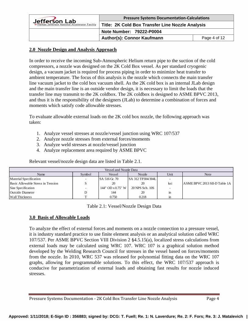
The purpose of this Engineering Note is to document the analysis that was performed to ensure
adequate nozzle design for the LCLS-II 2K Cold Box. A secondary motivation was also to
calculate the allowable nozzle loads that the main transfer line may safely impart on the 2K Cold
Box Vacuum Shell. Figure 1 provides a graphical representation of the 2K Cold Box nozzle that
connects to the main transferline. This nozzle connection joins the vacuum jacket (clamshell) of
the Sub-Atmospheric Return to the 2K Coldbox vacuum shell.
This report discusses the nozzle connection design (Section 2), the basis of the analysis that was
performed (Section 3), the calculations (Sections 4 through 7) and the summary / conclusion
(Section 8).
Figure 1: CP1 2K Cold Box Main Transfer Line Nozzle
CP1 2K Cold Box Vessel
CP1 Main Transfer Line
Nozzle Connection
Clamshell Section Approved: 1/11/2018; E-Sign ID : 356883; signed by: DCG: T. Fuell; Re. 1: N. Laverdure; Re. 2: F. Fors; Re. 3: J. Matalevich |
Pressure Systems Documentation-Calculations
Title: 2K Cold Box Transfer Line Nozzle Analysis
Note Number: 79222-P0004
Author(s): Connor Kaufmann Page 4 of 12
Pressure Systems Documentation - 2K Cold Box Transfer Line Nozzle Analysis Page 4
2.0 Nozzle Design and Analysis Approach
In order to receive the incoming Sub-Atmospheric Helium return pipe to the suction of the cold
compressors, a nozzle was designed on the 2K Cold Box vessel. As per standard cryogenic
design, a vacuum jacket is required for process piping in order to minimize heat transfer to
ambient temperature. The focus of this analysis is the nozzle which connects the main transfer
line vacuum jacket to the cold box vacuum shell. As the 2K cold box is an internal JLab design
and the main transfer line is an outside vendor design, it is necessary to limit the loads that the
transfer line may transmit to the 2K coldbox. The 2K coldbox is designed to ASME BPVC 2013,
and thus it is the responsibility of the designers (JLab) to determine a combination of forces and
moments which satisfy code allowable stresses.
To evaluate allowable external loads on the 2K cold box nozzle, the following approach was
taken:
1. Analyze vessel stresses at nozzle/vessel junction using WRC 107/537
2. Analyze nozzle stresses from external forces/moments
3. Analyze weld stresses at nozzle/vessel junction
4. Analyze replacement area required by ASME BPVC
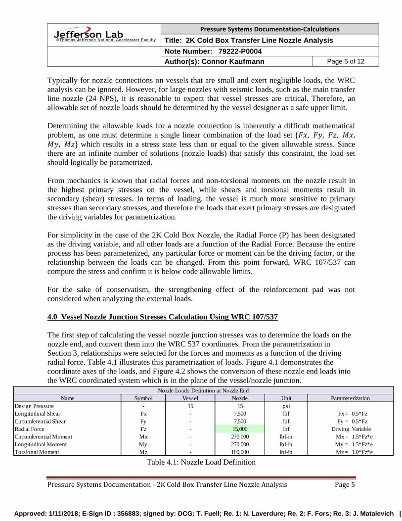
Relevant vessel/nozzle design data are listed in Table 2.1.
Table 2.1: Vessel/Nozzle Design Data
3.0 Basis of Allowable Loads
To analyze the effect of external forces and moments on a nozzle connection to a pressure vessel,
it is industry standard practice to use finite element analysis or an analytical solution called WRC
107/537. Per ASME BPVC Section VIII Division 2 §4.5.15(a), localized stress calculations from
external loads may be calculated using WRC 107. WRC 107 is a graphical solution method
developed by the Welding Research Council for stresses in the vessel based on forces/moments
from the nozzle. In 2010, WRC 537 was released for polynomial fitting data on the WRC 107
graphs, allowing for programmable solutions. To this effect, the WRC 107/537 approach is
conducive for parametrization of external loads and obtaining fast results for nozzle induced
stresses.
Name Symbol Vessel Nozzle Unit
Material Specification - SA 516 Gr. 70 SA 312 TP304/304L -
Basic Allowable Stress in Tension S 20 20 ksi ASME BPVC 2013 SII-D Table 1A
Size Specification - 144" OD x 0.75" W 20 NPS Sch. 10S -
Outside Diameter D 144 20 in
Wall Thickness T 0.750 0.218 in
Vessel and Nozzle Data
Note Approved: 1/11/2018; E-Sign ID : 356883; signed by: DCG: T. Fuell; Re. 1: N. Laverdure; Re. 2: F. Fors; Re. 3: J. Matalevich |
Pressure Systems Documentation-Calculations
Title: 2K Cold Box Transfer Line Nozzle Analysis
Note Number: 79222-P0004
Author(s): Connor Kaufmann Page 5 of 12
Pressure Systems Documentation - 2K Cold Box Transfer Line Nozzle Analysis Page 5
Typically for nozzle connections on vessels that are small and exert negligible loads, the WRC
analysis can be ignored. However, for large nozzles with seismic loads, such as the main transfer
line nozzle (24 NPS), it is reasonable to expect that vessel stresses are critical. Therefore, an
allowable set of nozzle loads should be determined by the vessel designer as a safe upper limit.
Determining the allowable loads for a nozzle connection is inherently a difficult mathematical
problem, as one must determine a single linear combination of the load set {𝐹𝑥, 𝐹𝑦, 𝐹𝑧, 𝑀𝑥,𝑀𝑦, 𝑀𝑧} which results in a stress state less than or equal to the given allowable stress. Since
there are an infinite number of solutions (nozzle loads) that satisfy this constraint, the load set
should logically be parametrized.
From mechanics is known that radial forces and non-torsional moments on the nozzle result in
the highest primary stresses on the vessel, while shears and torsional moments result in
secondary (shear) stresses. In terms of loading, the vessel is much more sensitive to primary
stresses than secondary stresses, and therefore the loads that exert primary stresses are designated
the driving variables for parametrization.
For simplicity in the case of the 2K Cold Box Nozzle, the Radial Force (P) has been designated
as the driving variable, and all other loads are a function of the Radial Force. Because the entire
process has been parameterized, any particular force or moment can be the driving factor, or the
relationship between the loads can be changed. From this point forward, WRC 107/537 can
compute the stress and confirm it is below code allowable limits.
For the sake of conservatism, the strengthening effect of the reinforcement pad was not
considered when analyzing the external loads.
4.0 Vessel Nozzle Junction Stresses Calculation Using WRC 107/537
The first step of calculating the vessel nozzle junction stresses was to determine the loads on the
nozzle end, and convert them into the WRC 537 coordinates. From the parametrization in
Section 3, relationships were selected for the forces and moments as a function of the driving
radial force. Table 4.1 illustrates this parametrization of loads. Figure 4.1 demonstrates the
coordinate axes of the loads, and Figure 4.2 shows the conversion of these nozzle end loads into
the WRC coordinated system which is in the plane of the vessel/nozzle junction.
Table 4.1: Nozzle Load Definition
Name Symbol Vessel Nozzle Unit
Design Pressure - 15 15 psi
Longitudinal Shear Fx - 7,500 lbf Fx = 0.5*Fz
Circumferential Shear Fy - 7,500 lbf Fy = 0.5*Fz
Radial Force Fz - 15,000 lbf Driving Variable
Circumferential Moment Mx - 270,000 lbf-in Mx = 1.5*Fz*e
Longitudinal Moment My - 270,000 lbf-in My = 1.5*Fz*e
Torsional Moment Mz - 180,000 lbf-in Mz = 1.0*Fz*e
Parameterization
Nozzle Loads Definition at Nozzle End Approved: 1/11/2018; E-Sign ID : 356883; signed by: DCG: T. Fuell; Re. 1: N. Laverdure; Re. 2: F. Fors; Re. 3: J. Matalevich |
Pressure Systems Documentation-Calculations
Title: 2K Cold Box Transfer Line Nozzle Analysis
Note Number: 79222-P0004
Author(s): Connor Kaufmann Page 6 of 12
Pressure Systems Documentation - 2K Cold Box Transfer Line Nozzle Analysis Page 6
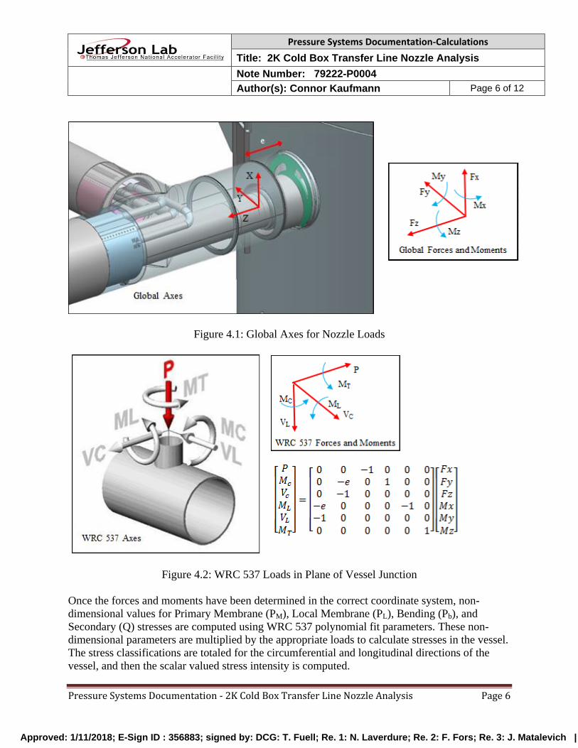
Figure 4.1: Global Axes for Nozzle Loads
Figure 4.2: WRC 537 Loads in Plane of Vessel Junction
Once the forces and moments have been determined in the correct coordinate system, non-
dimensional values for Primary Membrane (PM), Local Membrane (PL), Bending (Pb), and
Secondary (Q) stresses are computed using WRC 537 polynomial fit parameters. These non-
dimensional parameters are multiplied by the appropriate loads to calculate stresses in the vessel.
The stress classifications are totaled for the circumferential and longitudinal directions of the
vessel, and then the scalar valued stress intensity is computed.
Approved: 1/11/2018; E-Sign ID : 356883; signed by: DCG: T. Fuell; Re. 1: N. Laverdure; Re. 2: F. Fors; Re. 3: J. Matalevich |
Pressure Systems Documentation-Calculations
Title: 2K Cold Box Transfer Line Nozzle Analysis
Note Number: 79222-P0004
Author(s): Connor Kaufmann Page 7 of 12
Pressure Systems Documentation - 2K Cold Box Transfer Line Nozzle Analysis Page 7
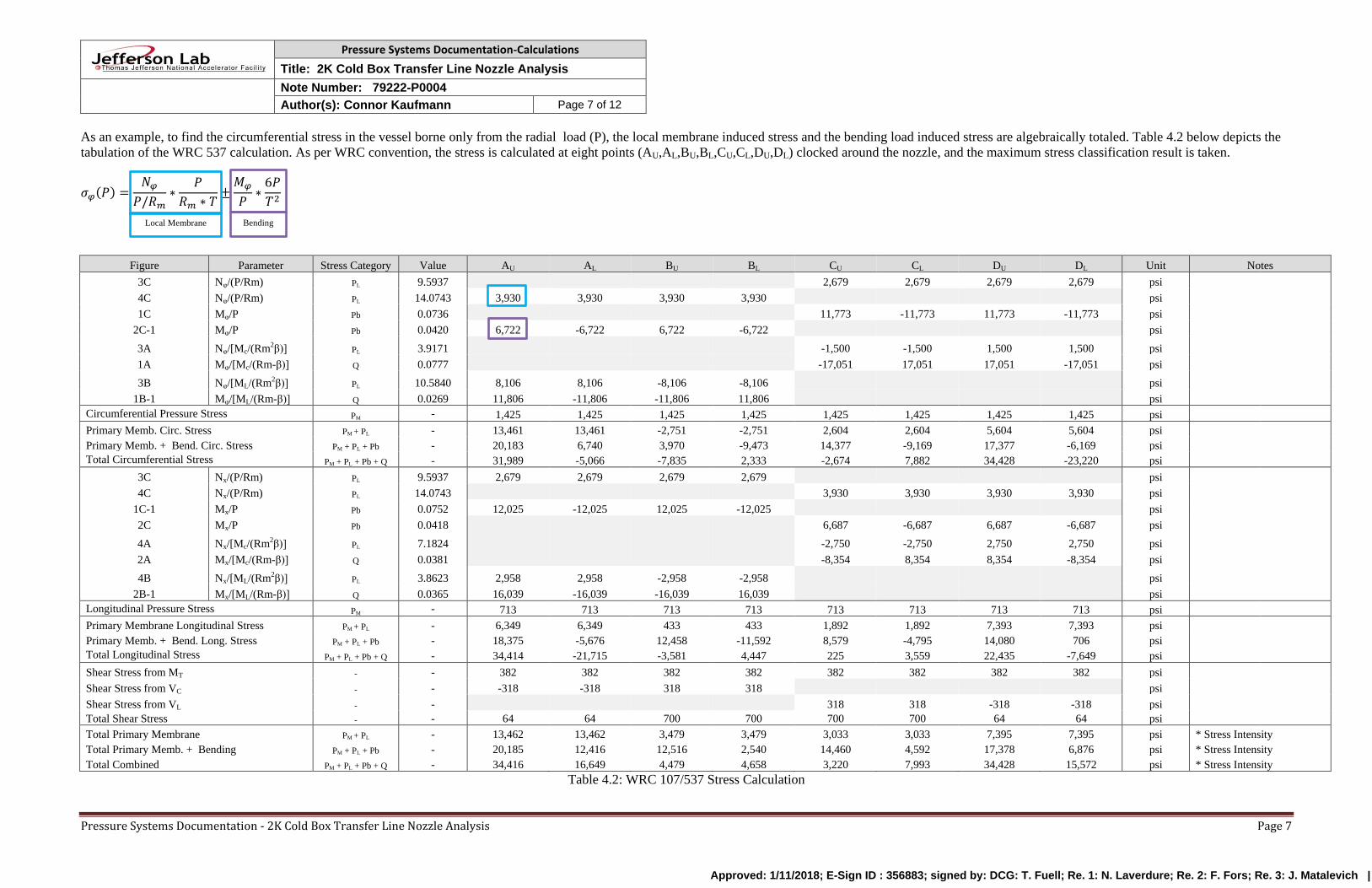
As an example, to find the circumferential stress in the vessel borne only from the radial load (P), the local membrane induced stress and the bending load induced stress are algebraically totaled. Table 4.2 below depicts the
tabulation of the WRC 537 calculation. As per WRC convention, the stress is calculated at eight points (AU,AL,BU,BL,CU,CL,DU,DL) clocked around the nozzle, and the maximum stress classification result is taken.
𝜎𝜑(𝑃) =𝑁𝜑
𝑃/𝑅𝑚∗
𝑃
𝑅𝑚 ∗ 𝑇±𝑀𝜑
𝑃∗6𝑃
𝑇2
Figure Parameter Stress Category Value AU AL BU BL CU CL DU DL Unit Notes
3C Nφ/(P/Rm) PL 9.5937 2,679 2,679 2,679 2,679 psi
4C Nφ/(P/Rm) PL 14.0743 3,930 3,930 3,930 3,930 psi
1C Mφ/P Pb 0.0736 11,773 -11,773 11,773 -11,773 psi
2C-1 Mφ/P Pb 0.0420 6,722 -6,722 6,722 -6,722 psi
3A Nφ/[Mc/(Rm2β)] PL 3.9171 -1,500 -1,500 1,500 1,500 psi
1A Mφ/[Mc/(Rm-β)] Q 0.0777 -17,051 17,051 17,051 -17,051 psi
3B Nφ/[ML/(Rm2β)] PL 10.5840 8,106 8,106 -8,106 -8,106 psi
1B-1 Mφ/[ML/(Rm-β)] Q 0.0269 11,806 -11,806 -11,806 11,806 psi
Circumferential Pressure Stress PM - 1,425 1,425 1,425 1,425 1,425 1,425 1,425 1,425 psi
Primary Memb. Circ. Stress PM + PL - 13,461 13,461 -2,751 -2,751 2,604 2,604 5,604 5,604 psi
Primary Memb. + Bend. Circ. Stress PM + PL + Pb - 20,183 6,740 3,970 -9,473 14,377 -9,169 17,377 -6,169 psi
Total Circumferential Stress PM + PL + Pb + Q - 31,989 -5,066 -7,835 2,333 -2,674 7,882 34,428 -23,220 psi
3C Nx/(P/Rm) PL 9.5937 2,679 2,679 2,679 2,679 psi
4C Nx/(P/Rm) PL 14.0743 3,930 3,930 3,930 3,930 psi
1C-1 Mx/P Pb 0.0752 12,025 -12,025 12,025 -12,025 psi
2C Mx/P Pb 0.0418 6,687 -6,687 6,687 -6,687 psi
4A Nx/[Mc/(Rm2β)] PL 7.1824 -2,750 -2,750 2,750 2,750 psi
2A Mx/[Mc/(Rm-β)] Q 0.0381 -8,354 8,354 8,354 -8,354 psi
4B Nx/[ML/(Rm2β)] PL 3.8623 2,958 2,958 -2,958 -2,958 psi
2B-1 Mx/[ML/(Rm-β)] Q 0.0365 16,039 -16,039 -16,039 16,039 psi
Longitudinal Pressure Stress PM - 713 713 713 713 713 713 713 713 psi
Primary Membrane Longitudinal Stress PM + PL - 6,349 6,349 433 433 1,892 1,892 7,393 7,393 psi
Primary Memb. + Bend. Long. Stress PM + PL + Pb - 18,375 -5,676 12,458 -11,592 8,579 -4,795 14,080 706 psi
Total Longitudinal Stress PM + PL + Pb + Q - 34,414 -21,715 -3,581 4,447 225 3,559 22,435 -7,649 psi
Shear Stress from MT - - 382 382 382 382 382 382 382 382 psi
Shear Stress from VC - - -318 -318 318 318 psi
Shear Stress from VL - - 318 318 -318 -318 psi
Total Shear Stress - - 64 64 700 700 700 700 64 64 psi
Total Primary Membrane PM + PL - 13,462 13,462 3,479 3,479 3,033 3,033 7,395 7,395 psi * Stress Intensity
Total Primary Memb. + Bending PM + PL + Pb - 20,185 12,416 12,516 2,540 14,460 4,592 17,378 6,876 psi * Stress Intensity
Total Combined PM + PL + Pb + Q - 34,416 16,649 4,479 4,658 3,220 7,993 34,428 15,572 psi * Stress Intensity
Table 4.2: WRC 107/537 Stress Calculation
Local Membrane Bending
Approved: 1/11/2018; E-Sign ID : 356883; signed by: DCG: T. Fuell; Re. 1: N. Laverdure; Re. 2: F. Fors; Re. 3: J. Matalevich |
Pressure Systems Documentation-Calculations
Title: 2K Cold Box Transfer Line Nozzle Analysis
Note Number: 79222-P0004
Author(s): Connor Kaufmann Page 8 of 12
Pressure Systems Documentation - 2K Cold Box Transfer Line Nozzle Analysis Page 8
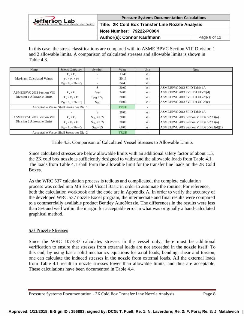
In this case, the stress classifications are compared with to ASME BPVC Section VIII Division 1
and 2 allowable limits. A comparison of calculated stresses and allowable limits is shown in
Table 4.3.
Table 4.3: Comparison of Calculated Vessel Stresses to Allowable Limits
Since calculated stresses are below allowable limits with an additional safety factor of about 1.5,
the 2K cold box nozzle is sufficiently designed to withstand the allowable loads from Table 4.1.
The loads from Table 4.1 shall form the allowable limit for the transfer line loads on the 2K Cold
Boxes.
As the WRC 537 calculation process is tedious and complicated, the complete calculation
process was coded into MS Excel Visual Basic in order to automate the routine. For reference,
both the calculation workbook and the code are in Appendix A. In order to verify the accuracy of
the developed WRC 537 nozzle Excel program, the intermediate and final results were compared
to a commercially available product Bentley AutoNozzle. The differences in the results were less
than 5% and well within the margin for acceptable error in what was originally a hand-calculated
graphical method.
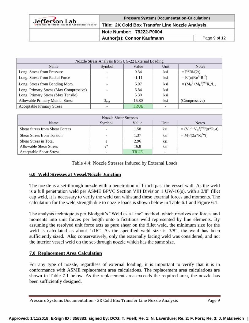
5.0 Nozzle Stresses
Since the WRC 107/537 calculates stresses in the vessel only, there must be additional
verification to ensure that stresses from external loads are not exceeded in the nozzle itself. To
this end, by using basic solid mechanics equations for axial loads, bending, shear and torsion,
one can calculate the induced stresses in the nozzle from external loads. All the external loads
from Table 4.1 result in nozzle stresses lower than allowable limits, and thus are acceptable.
These calculations have been documented in Table 4.4.
Stress Category Symbol Value Unit
PM + PL - 13.46 ksi
PM + PL + Pb - 20.19 ksi
PM + PL + Pb + Q - 34.43 ksi
- S 20.00 ksi ASME BPVC 2013 SII-D Table 1A
PM + PL SPM 24.00 ksi ASME BPVC 2013 SVIII D1 UG-23(d)
PM + PL + Pb SPM + SB 30.00 ksi ASME BPVC 2013 SVIII D1 UG-23(c)
PM + PL + Pb + Q SPS 60.00 ksi ASME BPVC 2013 SVIII D1 UG-23(e)
TRUE -
- S 20.00 ksi ASME BPVC 2013 SII-D Table 1A
PM + PL SPL =1.5S 30.00 ksi ASME BPVC 2015 Section VIII D2 5.2.2.4(a)
PM + PL + Pb SPL =1.5S 30.00 ksi ASME BPVC 2015 Section VIII D2 5.2.2.4(a)
PM + PL + Pb + Q SPS = 3S 60.00 ksi ASME BPVC 2015 Section VIII D2 5.5.6.1(d)(1)
TRUE -
Note
Acceptable Vessel Shell Stress per Div. 2
Acceptable Vessel Shell Stress per Div. 1
ASME BPVC 2013 Section VIII
Division 1 Allowable Limits
Maximum Calculated Values
ASME BPVC 2015 Section VIII
Division 2 Allowable Limits
Name Approved: 1/11/2018; E-Sign ID : 356883; signed by: DCG: T. Fuell; Re. 1: N. Laverdure; Re. 2: F. Fors; Re. 3: J. Matalevich |
Pressure Systems Documentation-Calculations
Title: 2K Cold Box Transfer Line Nozzle Analysis
Note Number: 79222-P0004
Author(s): Connor Kaufmann Page 9 of 12
Pressure Systems Documentation - 2K Cold Box Transfer Line Nozzle Analysis Page 9
Nozzle Stress Analysis from UG-22 External Loading
Name Symbol Value Unit Notes
Long. Stress from Pressure - 0.34 ksi = P*Ri/(2t)
Long. Stress from Radial Force - -1.11 ksi = F/(π(Ro2-Ri2)
Long. Stress from Bending Mom. - 6.07 ksi = (MC2+ML
2)0.5Ro/Ixx
Long. Primary Stress (Max Compressive) - 6.84 ksi
Long. Primary Stress (Max Tensile) 5.30 ksi
Allowable Primary Memb. Stress SPM 15.80 ksi (Compressive)
Acceptable Primary Stress - TRUE -
Nozzle Shear Stresses
Name Symbol Value Unit Notes
Shear Stress from Shear Forces - 1.58 ksi = (VL2+VC
2)0.5/(π*Ri*t)
Shear Stress from Torsion - 1.37 ksi = MT/(2π*Ri2*t)
Shear Stress in Total τ 2.96 ksi
Allowable Shear Stress τ* 16.8 ksi
Acceptable Shear Stress - TRUE -
Table 4.4: Nozzle Stresses Induced by External Loads
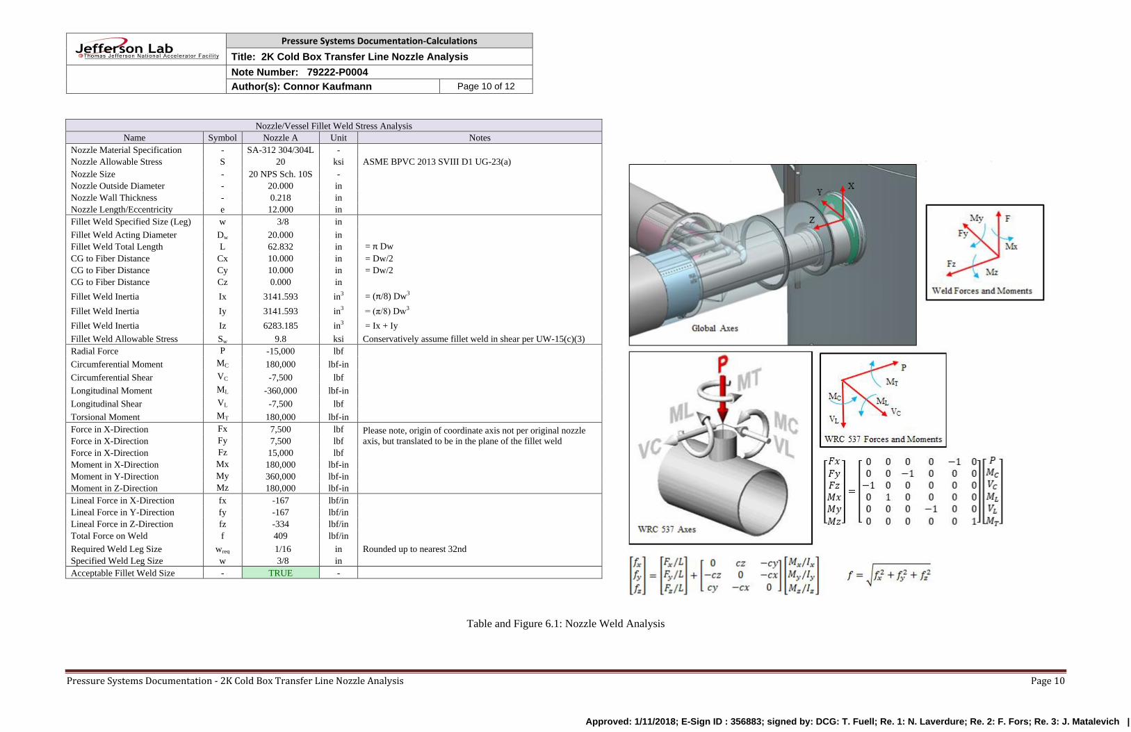
6.0 Weld Stresses at Vessel/Nozzle Junction
The nozzle is a set-through nozzle with a penetration of 1 inch past the vessel wall. As the weld
is a full penetration weld per ASME BPVC Section VIII Division 1 UW-16(s), with a 3/8” fillet
cap weld, it is necessary to verify the weld can withstand these external forces and moments. The
calculation for the weld strength due to nozzle loads is shown below in Table 6.1 and Figure 6.1.
The analysis technique is per Blodgett’s “Weld as a Line” method, which resolves are forces and
moments into unit forces per length onto a fictitious weld represented by line elements. By
assuming the resolved unit force acts as pure shear on the fillet weld, the minimum size for the
weld is calculated as about 1/16”. As the specified weld size is 3/8”, the weld has been
sufficiently sized. Also conservatively, only the externally facing weld was considered, and not
the interior vessel weld on the set-through nozzle which has the same size.
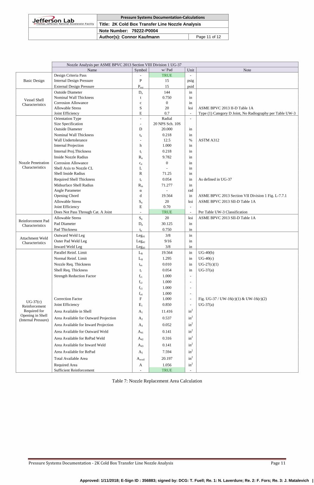
7.0 Replacement Area Calculation
For any type of nozzle, regardless of external loading, it is important to verify that it is in
conformance with ASME replacement area calculations. The replacement area calculations are
shown in Table 7.1 below. As the replacement area exceeds the required area, the nozzle has
been sufficiently designed.
Approved: 1/11/2018; E-Sign ID : 356883; signed by: DCG: T. Fuell; Re. 1: N. Laverdure; Re. 2: F. Fors; Re. 3: J. Matalevich |
Pressure Systems Documentation-Calculations
Title: 2K Cold Box Transfer Line Nozzle Analysis
Note Number: 79222-P0004
Author(s): Connor Kaufmann Page 10 of 12
Pressure Systems Documentation - 2K Cold Box Transfer Line Nozzle Analysis Page 10
Nozzle/Vessel Fillet Weld Stress Analysis
Name Symbol Nozzle A Unit Notes
Nozzle Material Specification - SA-312 304/304L -
Nozzle Allowable Stress S 20 ksi ASME BPVC 2013 SVIII D1 UG-23(a)
Nozzle Size - 20 NPS Sch. 10S -
Nozzle Outside Diameter - 20.000 in
Nozzle Wall Thickness - 0.218 in
Nozzle Length/Eccentricity e 12.000 in
Fillet Weld Specified Size (Leg) w 3/8 in
Fillet Weld Acting Diameter Dw 20.000 in
Fillet Weld Total Length L 62.832 in = π Dw
CG to Fiber Distance Cx 10.000 in = Dw/2
CG to Fiber Distance Cy 10.000 in = Dw/2
CG to Fiber Distance Cz 0.000 in
Fillet Weld Inertia Ix 3141.593 in3 = (π/8) Dw3
Fillet Weld Inertia Iy 3141.593 in3 = (π/8) Dw3
Fillet Weld Inertia Iz 6283.185 in3 = Ix + Iy
Fillet Weld Allowable Stress Sw 9.8 ksi Conservatively assume fillet weld in shear per UW-15(c)(3)
Radial Force P -15,000 lbf
Circumferential Moment MC 180,000 lbf-in
Circumferential Shear VC -7,500 lbf
Longitudinal Moment ML -360,000 lbf-in
Longitudinal Shear VL -7,500 lbf
Torsional Moment MT 180,000 lbf-in
Force in X-Direction Fx 7,500 lbf Please note, origin of coordinate axis not per original nozzle
axis, but translated to be in the plane of the fillet weld Force in X-Direction Fy 7,500 lbf
Force in X-Direction Fz 15,000 lbf
Moment in X-Direction Mx 180,000 lbf-in
Moment in Y-Direction My 360,000 lbf-in
Moment in Z-Direction Mz 180,000 lbf-in
Lineal Force in X-Direction fx -167 lbf/in
Lineal Force in Y-Direction fy -167 lbf/in
Lineal Force in Z-Direction fz -334 lbf/in
Total Force on Weld f 409 lbf/in
Required Weld Leg Size wreq 1/16 in Rounded up to nearest 32nd
Specified Weld Leg Size w 3/8 in
Acceptable Fillet Weld Size - TRUE -
Table and Figure 6.1: Nozzle Weld Analysis
Approved: 1/11/2018; E-Sign ID : 356883; signed by: DCG: T. Fuell; Re. 1: N. Laverdure; Re. 2: F. Fors; Re. 3: J. Matalevich |
Pressure Systems Documentation-Calculations
Title: 2K Cold Box Transfer Line Nozzle Analysis
Note Number: 79222-P0004
Author(s): Connor Kaufmann Page 11 of 12
Pressure Systems Documentation - 2K Cold Box Transfer Line Nozzle Analysis Page 11
Nozzle Analysis per ASME BPVC 2013 Section VIII Division 1 UG-37
Name Symbol w/ Pad Unit Note
Basic Design
Design Criteria Pass - TRUE -
Internal Design Pressure P 15 psig
External Design Pressure Pext 15 psid
Vessel Shell
Characteristics
Outside Diameter Do 144 in
Nominal Wall Thickness t 0.750 in
Corrosion Allowance c 0 in
Allowable Stress S 20 ksi ASME BPVC 2013 II-D Table 1A
Joint Efficiency E 0.7 - Type (1) Category D Joint, No Radiography per Table UW-3
Nozzle Penetration
Characteristics
Orientation Type - Radial -
Size Specification - 20 NPS Sch. 10S
Outside Diameter D 20.000 in
Nominal Wall Thickness tn 0.218 in
Wall Undertolerance - 12.5 % ASTM A312
Internal Projection h 1.000 in
Internal Proj.Thickness ti 0.218 in
Inside Nozzle Radius Rn 9.782 in
Corrosion Allowance cn 0 in
Shell Axis to Nozzle CL L - in
Shell Inside Radius R 71.25 in
Required Shell Thickness tr 0.054 in As defined in UG-37
Midsurface Shell Radius Rm 71.277 in
Angle Parameter α - rad
Opening Chord d 19.564 in ASME BPVC 2013 Section VII Division 1 Fig. L-7.7.1
Allowable Stress Sn 20 ksi ASME BPVC 2013 SII-D Table 1A
Joint Efficiency E 0.70 -
Does Not Pass Through Cat. A Joint - TRUE - Per Table UW-3 Classification
Reinforcement Pad
Characteristics
Allowable Stress Sp 20 ksi ASME BPVC 2013 SII-D Table 1A
Pad Diameter Dp 30.125 in
Pad Thickness te 0.750 in
Attachment Weld
Characteristics
Outward Weld Leg Leg41 3/8 in
Outer Pad Weld Leg Leg42 9/16 in
Inward Weld Leg Leg43 3/8 in
UG-37(c)
Reinforcement
Required for
Opening in Shell
(Internal Pressure)
Parallel Reinf. Limit LR 19.564 in UG-40(b)
Normal Reinf. Limit LH 1.295 in UG-40(c)
Nozzle Req. Thickness trn 0.010 in UG-27(c)(1)
Shell Req. Thickness tr 0.054 in UG-37(a)
Strength Reduction Factor fr1 1.000 -
fr2 1.000 -
fr3 1.000 -
fr4 1.000 -
Correction Factor F 1.000 - Fig. UG-37 / UW-16(c)(1) & UW-16(c)(2)
Joint Efficiency E1 0.850 - UG-37(a)
Area Available in Shell A1 11.416 in2
Area Available for Outward Projection A2 0.537 in2
Area Available for Inward Projection A3 0.052 in2
Area Available for Outward Weld A41 0.141 in2
Area Available for RePad Weld A42 0.316 in2
Area Available for Inward Weld A43 0.141 in2
Area Available for RePad A5 7.594 in2
Total Available Area Aavail 20.197 in2
Required Area A 1.056 in2
Sufficient Reinforcement - TRUE -
Table 7: Nozzle Replacement Area Calculation
Approved: 1/11/2018; E-Sign ID : 356883; signed by: DCG: T. Fuell; Re. 1: N. Laverdure; Re. 2: F. Fors; Re. 3: J. Matalevich |
Pressure Systems Documentation-Calculations
Title: 2K Cold Box Transfer Line Nozzle Analysis
Note Number: 79222-P0004
Author(s): Connor Kaufmann Page 12 of 12
Pressure Systems Documentation - 2K Cold Box Transfer Line Nozzle Analysis Page 12
8.0 Conclusion and Summary
In conclusion, the allowable loads for the 2K Cold Box Transfer Line nozzle have been
established. These established allowable loads meet the allowable stress standards of ASME
BPVC 2013 Section VIII Division 1 and Division 2, and thus the design is acceptable.
9.0 References
[1] Rules for Construction of Pressure Vessels, ASME BPVC 2013 Section VIII Division 1
[2] Rules for Construction of Pressure Vessels: Alternative Rules, ASME BPVC 2015 Section
VIII Division 2
[3] Local Stresses in Spherical and Cylindrical Shells Due to External Loads, WRC Bulletin
107, 2002 Update to 1965 Original version
[4] Precision Equations and Enhanced Diagrams for Local Stresses in Spherical and Cylindrical
Shells Due to External Loadings for Implementation of WRC Bulletin 107, WRC Bulletin
537, 2013 Update to 2010 Original version
[5] Design of Welded Structures, Blodgett, 1966
Appendix A
The calculations, code and supporting files for this technical report are located at:
Document Location
Report M:\cryo\LCLS II ANALYSIS FOLDER\SCB - TL Nozzle\Reports
Excel Calculations M:\cryo\LCLS II ANALYSIS FOLDER\SCB - TL Nozzle\Excel
AutoNozzle Model M:\cryo\LCLS II ANALYSIS FOLDER\SCB - TL Nozzle\AutoNozzle
Approved: 1/11/2018; E-Sign ID : 356883; signed by: DCG: T. Fuell; Re. 1: N. Laverdure; Re. 2: F. Fors; Re. 3: J. Matalevich |


![[501] TILES AND ROLLS WELDING (HEAT AND COLD ......Cold welding type T is delivered in kit including: Ref.: 95607 from ROMUS - semi-pasty product, - guide nozzle in the shape of «T»,](https://img.pdfslide.net/doc/110x75/60be37da74161f6d5d66a2dd/501-tiles-and-rolls-welding-heat-and-cold-cold-welding-type-t-is-delivered.jpg)